
Evolution of Equipment in Electromobility and Autonomous Driving Regarding Safety Issues


Department of Electrical and Computer Engineering, Democritus University of Thrace, 67100 Xanthi, Greece
*
Author to whom correspondence should be addressed.
Energies 2023, 16(3), 1271; https://doi.org/10.3390/en16031271
Submission received: 25 November 2022
/
Revised: 19 January 2023
/
Accepted: 22 January 2023
/
Published: 25 January 2023
(This article belongs to the Special Issue Electric and Hybrid Vehicles: Technology Trends, Challenges and Opportunities)
Abstract
:Over the years, an increase in the traffic of electric and hybrid electric vehicles and vehicles with hydrogen cells is being observed, while at the same time, self-driving cars are appearing as a modern trend in transportation. As the years pass, their equipment will evolve. So, considering the progress in vehicle equipment over the years, additional technological innovations and applications should be proposed in the near future. Having that in mind, an analytical review of the progress of equipment in electromobility and autonomous driving is performed in this paper. The outcomes of this review comprise hints for additional complementary technological innovations, applications, and operating constraints along with proposals for materials, suggestions and tips for the future. The aforementioned hints and tips aim to help in securing proper operation of each vehicle part and charging equipment in the future, and make driving safer in the future. Finally, this review paper concludes with a discussion and bibliographic references.
1. Introduction
Electric vehicles (EVs) are becoming more popular with time. Based on Reference [1], this type of vehicle is driven by at least one non-peripheral electric motor, which draws its energy mainly from an electric rechargeable energy storage system (battery pack). This storage system is recharged mostly by using an external energy supply system [1]. EVs date from the early days of transportation and comparing with conventional gasoline and diesel vehicles, they present by far a higher energy efficiency ratio [2]. In general, EVs are divided into three main categories; battery (BEVs), hybrid (HEVs) and fuel cell electric vehicles (FCEVs) [1].
EVs accelerate fast, achieving speeds almost comparable to those of conventional vehicles [2]. Additionally, they are environmentally friendly, because they produce zero direct emissions. This fact contributes to the reduction of air and carbon pollution from the transportation sector, which is a strong advantage of EVs against conventional vehicles. Other advantages of EVs are the low maintenance costs, due to their simple mechanical structure, the promotion of new technologies, such as Vehicle to Grid (V2G) operation, and their suitability in urban centers [1]. On the other hand, conventional vehicles can achieve higher speeds and longer distances compared to EVs, while, because of their silent electric motors and frequent use in urban centers, EVs are not easily perceived by pedestrians [1,2].
A basic system of EVs is the high voltage circuit, where the basic parts of the vehicle’s equipment are connected together by bright orange high voltage wires [3]. According to Reference [3], the circuit is closed by high voltage service disconnects, which are located in the rear part of the EV and consist of thermal sensors and control units, in order to monitor their operation. The voltage in the circuit starts from 48 Volts DC (VDC); in normal conditions, it can reach the maximum voltage that the battery pack can handle under normal conditions (about 600 VDC), and in danger exceeds 800 VDC [3,4].
Other features of a typical EV include a 12 Volt battery, which is needed for the operation of the vehicle’s electronics, badges indicating that the vehicle is electric, and the absence of an exhaust [3,5]. In addition, there are safety systems in the car; the Electronic Stability Program (ESP program) is an active safety system that provides two other active safety systems: an anti-lock braking (ABS) system, which prevents the wheels from locking during braking, and a traction control system (TCS), which prevents the wheels from spinning when the vehicle starts off and accelerates [6]. Additionally, other parts include a set of airbags (six to seven in a typical European electric car) and seatbelt pretensioners, a vehicle collision detection system, a control unit for the air conditioning and heating systems, the dashboard of the car, and a set of electrical and electronic components [3,5].
A typical BEV consists of a propulsion system and a battery-charging facility, which are connected by a high-voltage circuit. The propulsion system includes an electric motor, a battery pack, converters located next to both of them, and buck-boost choppers [1,7]. An electric car powertrain is depicted in the figure below (Figure 1) [8].
The electric motors that are used in EVs include brushed direct current (DC) motors, induction motors, synchronous reluctance motors, and permanent magnet synchronous and brushless DC motors [1]. The most commonly used battery packs in BEVs and HEVs are nickel-metal hydride (NiMH), lithium-Ion (Li-Ion) and lithium-polymer (LiPolymer) batteries [1]. The battery charging facility, which can be used either at home or at public charging stations in order to charge the EV, allows either on-board or off-board charging, or both [9].
Apart from pure electric cars, hybrid electric cars represent another major vehicle category. Hybrid electric vehicles include an internal combustion engine (ICE) connected with an electric motor or generator (in some vehicles), buck-boost converters and a battery pack. The fuel, usually diesel, is stored in a tank that is highly resistant to high pressures, temperatures and corrosion [10]. There are also valves and quantity and pressure sensors, in order to control the pressure and the flow of the fuel into the transfer pumps [10]. This type of vehicle is more efficient for long-distance trips and develops higher speeds than a BEV, but should be maintained more often, due to its complexity. Respectively, the maximum developed voltage in hybrid electric vehicles is around 650 VDC [10].
EVs with hydrogen fuel cells are another category. This type of car uses hydrogen as fuel for its operation. This kind of fuel is stored in a tank usually made of carbon fiber. Inside the tank, the fuel pressure for optimal and safe operation must be 700 bar (70 MPa) [11], while the fuel temperature fluctuates between −40 °C and 85 °C [12]. The maximum pressure of the fuel that the tank can carry is 172 MPa at a minimum [13]. A pumping system is used in order to help the hydrogen flow from the tank to the fuel cells [14], while excessive flow and any hydrogen leakage are detected by sensors, most of them located near the cabin [13]. In FCEVs, the maximum developed voltage is around 500 VDC in some vehicles. Exceeding the voltage can cause short circuits, which lead to extensive vehicle equipment damage and total explosion of the car [15].
A modern, quite popular driving ability is autonomous driving. According to Reference [16], autonomous driving is a driving ability where the vehicle has the ability to sense its surroundings and move within defined lanes without human interaction. Based on References [16,17], autonomous cars use sensors, a lidar system, camera and mapping applications, in order to map around their routing area and for moving. Taeihagh and Min Lim [17] note that the frequent use and extensive popularity of autonomous cars raise various problems, such as faults in their equipment, cybersecurity issues and even malicious use (such as kidnapping phenomena), leading to serious traffic accidents. In order to address them and make the use of self-driving cars safer, new technologies will need to be proposed.
In recent years, EVs have been gaining ground in the global transportation market. According to the global EV outlook for 2022 [18], nearly 10% of global car sales were for electric vehicles in 2021, whereas 16.5 million electric cars were on the road. In the first quarter of 2022, 2 million electric cars were sold, 75% more than in the same period in 2021. The number of public chargers is increasing continuously, in order to reach over 15 million units by 2030. China and the United States are the two countries with the largest number of electric vehicles in circulation on the planet. In the coming years, the number of electric vehicles plying the roads worldwide will increase such that, by 2030, the total global electric vehicle stock may reach almost 145 million vehicles, and annual sales may exceed 25 million (reaching almost 15 million cars in 2025) [19].
Taking into consideration, on one hand, the occurrence of serious accidents in the last 12 years (2010–2022) involving such vehicles (electric, hybrid electric, hydrogen fuel cell and self-driving), and on the other hand, the progress in the development of the aforementioned vehicle equipment over time with regard to safety issues, the goal of this is to propose additional technological innovations, applications or materials for use in the near future. Table 1 lists some of the electric car road accidents that occurred in the last 12 years (2010–2022)—which led to extensive fires—and the manner of response [20,21,22,23,24,25,26,27,28,29,30,31].
The paper is structured as follows. First, some introductory facts are presented regarding electric propulsion, existing technologies and the evolution of electric car use in the coming years. Then, a study of the risks and safety systems, associated with the usage of EVs, is conducted, with the need for equipment development emphasized. In addition, the evolution of the equipment used in electric and hybrid electric vehicles, hydrogen fuel cell vehicles, and self-driving cars as well as of the charging devices over time and in the near future are presented. Further, an assessment of electromagnetic interference mitigation equipment is also made. So, considering all of the above, the paper discusses additional technological innovations and applications related to the evolving equipment, with hints and tips for better operation of the equipment in the near future and proposals for new materials, all with the aim of facilitating better equipment function and safer vehicle operation. The final section of the paper summarizes the topics discussed and presents its conclusions, and is followed by bibliographic references.
2. Dangers Associated with Electric Cars and Safety
This chapter focuses on the dangers of EV use and the safety systems the vehicle has. Dangers and road accidents form the basis for electric car equipment development. The equipment is evolving, in order to help make the roads used by these vehicles safer, and to reduce the number of accidents as the years pass.
The increased use of electric vehicles poses dangers. Looking at EV incidents that have occurred in recent years, the risks arising from EVs can be generally categorized into major incident factors such as general EV damage, human factors, high-voltage circuit malfunctions, wear and tear of equipment, weathering, environmental effects and other risks related with EV system functions and faults in hybrid electric vehicle or hydrogen propulsion equipment [32]. Road accidents and vehicle submersion can cause extensive fires, serious toxicity (due to gas emissions and spill hazards) and electrical hazards, such as extensive short circuits, the development of electric arcs and discharges [5].
Generally, considering the accidents referred to in Table 1 [20,21,22,23,24,25,26,27,28,29,30,31], it seems that most accidents were caused either by general vehicle damage, due to excessive use, internal faults, or serious faults during charging, or by collisions with other vehicles or objects due to high speed, whereas accidents involving vehicle submersion in water or rollovers were less frequent. In all accidents, a fire was caused—either controlled or catastrophic—in some cases, there were human casualties, and there was a serious electrical risk.
Electric cars are equipped with various safety systems. Beyond the active and passive safety systems that were mentioned in the introduction, the cars are equipped with systems that ensure safety during use, such as an automatic shut-down system, adaptive cruise control system (ACC), blind spot and forward collision warning system, active brake assist, lane assist system, crash avoidance technology to prevent possible crashes, wrong-way driver warning systems and pedestrian and cyclist warning systems. In the future, all of these systems will be improved, whereas new technologies and trends such as lidars and cameras in electric cars, more flexible electric drive actuators, improved protection systems, advanced communication V2I models and improved battery management systems with data recording technology will be introduced [33,34,35,36].
Considering the accidents that have occurred and the increasing use of electric vehicles, electric car equipment designs will evolve. Based on the accidents and the advances in these vehicles’ designs, in the future their equipment will be constructed in such a way as to withstand greater current and voltage than the present equipment and have the ability to deal with any faults that may occur, thus preventing and leading to fewer accidents than at present. In the end, additional technological innovations and applications can be proposed in order to increase safety.
3. Advances in Electric Vehicle Equipment
3.1. Battery Pack
A battery pack is an important device for the propulsion of an electric vehicle [37]. In the battery pack, the cooling is carried out by the use of pipes, fans, refrigeration systems, electric pumps or cooling circuits, where water or dielectric fluid is circulating inside (water- or liquid-cooling) [38]. Current battery packs are equipped with busbars and a battery management system, including sensors (coolant water intrusion detection sensors, temperature and thermal sensors that measure temperature and prevent possible overheating and failures, sensors that detect thermal runaway, pressure and current), controllers and various measuring instruments, such as thermocouples and highly sensitive thermistors [39,40,41]. The system controls the operation of the battery, thus regulating its charging, collects information about battery operating status, checks the impedance, and detects possible faults and mitigates them [42]. In the end, the battery packs in EVs are equipped with one or more safety features including fuses, vents and current-interrupt devices [40].
Near the battery pack is located a thermal leakage protection system, which prevents thermal runaway and leakage by detecting possible electrolyte leakage and water immersion locally on the battery [39,43]. In addition, buck-boost DC/DC converters regulate current and voltage flow, thus boosting the output voltage. The most common types of batteries used in electric cars are, as referred to in the introduction, Li-Ion, LiPolymer and NiMH batteries, with lithium iron phosphate (LiFePO4) as a cathode material or cathodes with a high nickel content (for NiMH batteries). Additionally, silicon is preferred mostly as an anode material (silicon-based anode) [44].
Some of the specifications of power batteries through the years are shown in the following Table (Table 2). Based on Table 2, the capacities of the batteries and their battery voltage have been increasing over time; currently, the maximum voltage of 300 volts on average is about to surpass 800 volts, while the energy capacity of almost 60 kWh is about to exceed 100 kWh. In the literature, it appears that the specific energy has evolved in order to reach up to 1800 Wh/kg, with energy density of up to 1400 Wh/L and a life cycle ranging from 200 up to 18,000 cycles [45,46,47,48,49,50,51,52,53,54,55,56,57,58,59,60,61,62,63,64,65,66,67,68,69,70]. Nowadays, the batteries can withstand greater operating temperatures than before (70 °C versus 45 °C in previous years) [71]. The designs of the battery packs have been evolving in order to achieve greater voltages (over 850 V) in the near future, to have greater range on one charge (over 500 km), greater capacity and internal resistance (up to 1 MΩ), lower weight and longer lifespans, and to store energy with increased energy density. Nevertheless, the potential for short circuits or electrical faults, overvoltage conditions, overheating phenomena, and even fires will continue to exist, albeit to a lesser extent.
In the future, the battery packs and battery management systems, along with IG1 32 V/IG2 42 V protection fuses and circuit breakers, will be upgraded in order to withstand higher voltages and currents and achieve the maximum energy storage with the minimum weight, in order to store energy with higher energy density than currently and to mitigate overvoltages and overheating [42]. So, according to References [72,73,74], in the future, there will be electrodes in the batteries made from materials such as Kapton (facilitates attachment of electrodes with the separator), organic hydro peroxides (OHP), nanofibers, 1D/2D/3D nanofillers as polymer nanocomposites (such as ultrathin 2D graphene, carbon nanotubes, nanographene, nanosilica or nanoalumina), graphite, Ni-Al alloys, Ni-rich oxides and silicon carbon materials, because these materials offer better electrochemical performance and improved electrical conductivity. Based on Reference [75], the graphite, as an intercalation material, helps in thermal management, because it is resistant to temperature rise and overheating. The electrodes, based on References [75,76], may be immersed in ceramic polymer or succinonitrile electrolytes (SN) that are not flammable or significant pollutants, and will have a coating of graphene and lithium-silicon alloys. The cells may be either cylindrical or prismatic, as the battery pack will have to withstand higher voltages for improved safety [76].
According to research, in the future, new battery technologies may appear that will be more stable, reliable and safer, such as Li-S, Zn-Ion and Na-Ion batteries [77]. Additionally, Zn-type batteries (Zn-Ion or Zn-metal free) with 2D borophene as organic anode material may appear, since these batteries are more efficient, lighter and have a fairly high energy density [78].
3.2. Charging (and Charging Equipment)
Since the electric car operates with the use of a battery pack and an electric motor, the battery pack must be charged in order for the car to function correctly and move. So, an electric vehicle charging system consists of components that provide a DC output that is supplied to the vehicle for the purpose of recharging its storage batteries. This is because the battery stores energy in the form of DC voltage. In this case, there may be AC/DC chargers with rectifiers, half-bridge, full-bridge or multilevel converters (buck-boost or Cuk converters), or there may be DC/DC chargers [37,79].
Generally speaking, to charge EVs, on-board and off-board chargers are used. Well-grounded on-board chargers allow wireless, conductive or inductive charging, where there is no wiring, and they are preferred in terms of battery charging and electrical safety, [9,80]. On the other hand, off-board chargers can help in charging large vehicles and allow rapid charging [9,80].
Further, in the case of vehicle charging, the modalities include home charging and charging at parking lots and charge stations, where the charge is based on either SAE J1772 (in the United States), IEC 62196 (in Europe), or GB (in China) standards, or CHAdeMO for fast charging [81]. In terms of home charging, the charge is provided by a single-phase supply, takes 6 to 8 h, and the maximum charging current does not exceed 80 A, or 32 A in Europe in semi-fast charging [82,83], while the charging voltage reaches 115 volts [7]. On the other hand, charging in charging spots or parking areas and charge stations takes place when the vehicle is parked. The battery pack becomes fully charged when its current reaches or exceeds 100 A, and the charging procedure takes about an hour [7]. The charging plugs that are used are shown in Figure 2. As AC EV connectors, there are two types: Type 1 (based on the SAE J1772 standard) that can charge up to 7.4 kW, and the Type 2 Mennekes (based on the IEC 62196-2 standard) that can charge up to 43 kW and may be used for public charging [80,83]. On the other hand, EVs can charge up to 350 kW using EV DC connectors, up to 100–200 kW using CHAdeMO, and up to 350 kW with combined charging system (CCS) connectors [84].
For faster home charging, a single-phase or three-phase bidirectional on-board half-bridge charger is allowed, or a three-phase off-board charger that can handle excessively high voltages and currents, up to 500 and 600 volts [85,86]. Moreover, nowadays, there are two-stage onboard chargers with boost power factor correction converters, full-bridge rectifiers and resonant converters, off-board chargers with three-phase LCL active rectifiers, off-board chargers with LLC resonant converters, and direct and dual mode chargers or switched-mode chargers [84,87]. The majority of EV chargers offer static load balancing, which assumes manual load control [88]. In any case, the generations of plug-in electric vehicle grid interactions are shown in the following table (Table 3) [82].
According to Table 3, which shows the various generations of plug-in electric vehicle interactions, three generations of plug-in electric vehicle grid interactions are available today, and the fourth will be available for use in the future [82]. Specifically, the transition is being made from simple charging with plugs and cables in the past, to superchargers (CHAdeMO quick charging system) [89], wireless charging and vehicle-to-home energy transfer in emergency situations [82] currently and in the future. In Reference [90], it was pointed out that in some areas, such as in Nordic countries and the United Kingdom, the car is charged wirelessly with the use of prefabricated power modules buried underground. The vehicle is charged in directions along the track and in reverse, due to the development of an electromagnetic field during its movement. This technology is very modern and innovative, because the car is being charged without the use of plugs and chargers. According to researchers in the future, this type of charging will be used on a large scale and will be upgraded all over Europe and the world [91]. Dynamic wireless charging is depicted in the figure below (Figure 3) [92]. In fact, wireless charging may be assisted by wireless power transfer technologies, such as inductive power transfer and coupled magnetic resonance with low losses, because they will reduce any electromagnetic interference, thus improving the charging performance [93].
Furthermore, in the future, electric cars may be used as grid feeders. This can be seen in the case of smart charging, which in the future will be quite widespread. Smart charging is more practical than V2G, because when levels of demand are low, EVs provide power to the grid, whereas during periods of high demand, the reverse occurs [94]. The charger, in any case, will be made in such a way that it will withstand more voltage (even 1.5 kV) and will generate more electromagnetic interference than now, while overvoltages will also occur [95]. Additionally, it will be upgraded in order to reduce the car charging time, and could be improved with more communication capabilities than now and the implementation of upgraded controlling software [82]. Thus, according to Reference [96], it is estimated that there may be chargers that control the vehicle’s charge with an advanced charge equalization controller, that consist of more converters (buck-boost, Cuk and flyback converters) than now, in order to regulate and mitigate the overvoltages that occur. There may be more passive electromagnetic interference (EMI) filters in the chargers and charging facilities that will help reduce any electromagnetic interference.
3.3. High-Voltage Circuits
The high-voltage circuit is a very important part for EV locomotion. The circuit connects basic parts of the electric car (such as battery pack and electric motor), through insulated, bright orange high-voltage copper wires [3]. The circuit is closed by high-voltage service disconnects. The disconnects are located in the rear part of the EV (behind the back seats). In the event of an accident, the circuit should not be cut off [3]. Additionally, based on Reference [97], the power electronics that function in the circuit are buck-boost converters and bidirectional half and full-bridge converters with thyristors and on-board PWM inverters (high-powered electronics). Apart from the wiring, a water or liquid cooling system cools the circuit for smooth operation, while various relays and fuses control the circuit’s function [97]. Based on Reference [98], the main components of an automotive electric drive system and their connections are shown in Figure 4. In addition, there are sensors (Hall effect sensors) that can detect a fault in the circuit and overtemperature phenomena and can control possible current leakage by measuring the electric current in the circuit [99]. Further, there are mechanisms for protection against overvoltages and other electrical hazards [97].
Based on Reference [100], the voltage in a high-voltage circuit is designed to reach 850 volts, which is much higher than in past years. Today, the high-voltage circuit connects the power battery and the 12 volt battery with the electric motor (AC induction motor and permanent magnet motor). Some of the controllers that control circuit operation (three-phase inverters) and some wide-bandgap (WBG) semiconductors (WBG silicon-carbon (SiC) and gallium-nitride (GaN) WBG MOSFETs) represent a new trend and will be very popular in the future [101,102], along with semiconductors (SiC MOSFETs, Si-IGBTs) and resonant converters (resonant LLC converters) [101,103,104], beyond the high-powered electronics referred to above. A resonant LLC converter used in an electric car is depicted in the figure below (Figure 5) [104].
Power modules and high-powered electronics are constructed with metal ceramic substrates, such as copper-bonded substrates or silicon nitride ceramic substrates [105]. So, according to References [98,106], the high voltage circuit will be constructed in such way that it can distribute higher voltages than is the case today (higher than 850 V); however, losses, vibrations and magnetic leakages will still exist, though to a lesser extent. It will be connected with new-generation electric motors that operate at higher voltages and speeds. The cars will have an upgraded thermal management system that can cool the circuit. Ultimately, based on References [101,107], the circuit may be integrated with more advanced WBG devices and semiconductors than at present, such as freewheeling or junction barrier Schottky diodes, upgraded GaN and SiC devices and WBG-based inverters. These devices generally increase the safety of the circuit by reducing possible interrupts and electromagnetic interferences and providing better cooling and lower thermal conductivity. In the future, traction inverters with high power ratings (100–500 kW) or verified resonance converters are also expected [99,102].
Finally, the wiring may be upgraded in order to withstand greater current and voltage. Based on [108,109], the wiring may be made from ultrastrong graphene fibers or from aluminum with impurities of ceramics and titanium, with enhanced electrical and mechanical properties, in order to reduce possible losses and vibrations and to present better electrical conductivity, thermal management and high mechanical strain. Additionally, it is estimated that active shielding, ultrasonic welding for semiconductors or metal plating will reduce any magnetic leakages [107,108].
3.4. Electric Motors
Most electric cars use one or two electric motors for propulsion. The basic types of electric motors that are used in electric vehicles include DC motors (brushed or brushless DC motors are used commonly in later electric cars with axial or radial flux), induction motors, permanent magnet synchronous motors, switched reluctance motors (which help in the reduction of torque ripples), synchronous reluctance motors, as well as motors with die-cast copper rotors, motors with groove ball bearings, and axial flux motors [110,111,112,113]. The most common electric motors are permanent magnet and induction alternating current (AC) motors. In fact, the interior permanent magnet synchronous motor (IPMSM) using neodymium-iron-boron (NdFeB) magnets is a quite common technology in electric cars [101]. Electric motor function is controlled by buck-boost converters (located next to the motor) that regulate the flow of power and current in the motor [1]. The motor is cooled by a cooling system, where the cooling base is either water or air, consisting of pumps, a fan, heaters and temperature measuring sensors (e.g., thermistors), in order to maintain the motor’s operation at normal functioning temperatures [1]. The motor’s speed and torque are controlled by a speed controller or by calibrated torque meters, whereas various controllers reduce and control torque ripples [1]. Additionally, according to Reference [114], the electric motors contain high-density passive EMI filters, dampers and flywheels that mitigate electromagnetic interference and absorb possible vibrations and torque oscillations.
If a fault occurs in the electric motor, the driver must stop the car, turn off the engine, deactivate the high-voltage circuit by removing the high-voltage service disconnects, and remove fuses related to the electric motor’s function from the fuse box [3,5].
In Table 4, some electric motor specifications through the years are given.
According to this table, the power of the electric motor has been evolving, from almost 120 to 150 kW in 2010 to surpass 700 kW in some configurations nowadays [143,144]. The peak torque has been increasing year to year, from almost 200 Nm in the first generation of cars to over even 1500 Nm nowadays [75,76]. In the future, all these will be surmounted. The motors will evolve, allowing greater range (even over 500 km) than now, similar to that of internal combustion engine vehicles, and delivering higher speeds. Moreover, they will be operated at higher voltage and current [110].
So, according to References [110,145], in the future, electric motors may have upgraded insulation (insulation resistance should reach 20 MΩ), more bearings, and more sensors, valves and resistive active power filters. However, they will occupy less space in the electric car for greater efficiency, due to the fact that in the future, there will be a decrease in magnet volume or mass, or even an absence of the use of magnets. Further, according to Reference [110], the lamination thickness of motors may decrease, in order to mitigate possible eddy current losses. They also may be less noisy than today, with fewer vibrations [110].
Besides the current types of electric motors, according to References [146,147], die-cast squirrel-cage copper rotor induction motors or motors with compressed aluminum in the windings may be preferred for use in the future, because they have reduced rotor losses and higher electrical conductivity; otherwise, according to [148], motors with a nickel alloy rotor may be preferred. There may be electric cars with flux switching permanent magnet motors [146], IPMSM motors in wide use, Vernier-type permanent magnet motors, or permanent magnet motors with tooth-wound coils [149]. The geometry of a dual-stator Vernier-type permanent magnet motor is shown in the figure below (Figure 6) [150].
Additionally, brushless permanent magnet motors with regulated flow may also be popular, because these motors are more efficient compared to the most used electric motors [151]. The magnets may be made of graphite, in order to increase electrical conductivity, and to prevent possible faults [152]. Finally, permanent magnet motors with rare-earth magnets or motors without magnets (synchronous reluctance motors) may exist in the future, despite the reduction in heavy rare-earth content [111].
3.5. Supercapacitors
According to [153], supercapacitors, also known as ultracapacitors or electrochemical double-layer capacitors (EDLCs), are a form of electrical energy storage that are suited to situations that require energy storage for a short duration, yet capable of delivering high power. Supercapacitor technology is common and widespread in electric vehicles. Supercapacitors exist in electric cars with regenerative braking systems. This is thanks to their greater power density than chemical reaction-based batteries, which allows them to store electricity, collecting energy that is generated under braking [154]. In Reference [153], it was described that a common supercapacitor comprises two porous carbon (or nanocarbon) electrodes, connecting to current collectors, with each one immersed in an organic or aqueous or ionic liquid electrolyte and separated by a thin ion-permeable ceramic or glass-fiber membrane (separator). There are different types of supercapacitors depending on the energy storage: namely, electrochemical double-layer capacitors (EDLCs), pseudocapacitors with conducting polymers in electrodes (these capacitors can store energy faradaically through the charges) and hybrid supercapacitors (which store the charges by matching the capacitive carbon electrode with a pseudocapacitive or lithium-insertion electrode); these are depicted in the following figure (Figure 7) [155,156]. In addition, there are boost converters that regulate the supercapacitors’ operation and their recharge from the battery, and control the power flow and the current and voltage. Supercapacitors are excited by a DC voltage, and raise currents up to 400 A, while they contain Zener diodes to mitigate the reverse voltage [157].
On the other hand, spikes, vibrations, leakage and ignition lead to serious problems in operation and can cause fire [158]. Regarding any danger and fault in the supercapacitors, based on Reference [159], with the deactivation of the high-voltage circuit, the supercapacitors of the vehicle will be discharged. When the vehicle is switched off, the driver must wait approximately 5 min for the supercapacitors to discharge and must pay attention to any demagnetization, so measurements should be performed by magnetometers [160]. The smart key must be removed and kept in a safe place away from the vehicle, and the low-voltage power cord must be removed [160]. In the end, as mentioned by Reference [161], overheating phenomena, which may be caused by a hazard or fault during supercapacitor operation, are reduced by the heat management system.
Before 2000, supercapacitors stored electrical energy with a specific energy density lower than 6 Wh/kg and overall energy lower than 400 Wh. Nowadays, they store with a specific energy density of up to 300 Wh/kg [162]. In the future, supercapacitors will evolve the ability to withstand greater voltages than at present (reaching up to 2000 volts), the capacity to store energy with higher energy density (specific energy density higher than 300 Wh/kg), and have longer lifespans. The increased capacity will improve car efficiency [163,164]. However, overheating phenomena will remain, and overvoltages and overcurrents will continue to appear. So, according to References [163,165,166], there will be flexible and wearable high-performance supercapacitors with electrodes that may be made of high-conductivity active materials and ternary composites (such as conducting polymers, polyanilines, PPy-polypyrrole, carbon nanotubes, activated carbon, black phosphorus nanoparticles, graphene or metal oxides together with nanotubes or graphene). Supercapacitors will contain a heat management system with cooling plates and brushes, so that the operating temperature will remain at normal levels. Overvoltages and overcurrents may be somewhat mitigated by frequency adjustments [161].
4. Advances in Hybrid Electric Vehicles’ Equipment
As mentioned in the introduction, hybrid electric vehicles have quite complex equipment that requires continuous maintenance. According to References [167,168], the common equipment for electric cars consists of an internal combustion engine (ICE) in combination with an electric motor, an electric generator (in some vehicles) connected to the ICE, buck-boost converters, a high-capacity battery pack (mainly Li-Ion and NiMH) with high energy density cells and fuel tank. The electric motor drives the front axle of the vehicle through an automatic mechanical transmission (AMT) system [160]. Various configurations that exist in hybrid electric vehicles are: series HEV, parallel HEV, series-parallel HEV or complex HEV configurations [169]. There are also valves and quantity and pressure sensors that control the pressure and the flow of the fuel into the transfer pumps [10]. The cooling of the hybrid electric car system is conducted by a system of radial coolant pumps, assisted by the car’s air conditioning system [170]. In addition, the equipment also includes supercapacitors and flywheels that store electrical and kinetic energy (hybrid energy storage with supercapacitors), supplying the car with extra energy besides that from the battery packs [169]. According to Reference [171], a speed controller and velocity advisory system control the vehicle’s movement. In hybrid electric cars, also according to Reference [171], there is a system that monitors the traffic on the road near the vehicle using the Global Positioning System (GPS), radar or Geographic Information System (GIS), which, in conjunction with the vehicle speed controller, helps the vehicle achieve better fuel management and movement. The structural diagram of a plug-in hybrid electric vehicle, based on Reference [167], is depicted in Figure 8.
Over the years, the equipment has been upgraded and changed, in the sense that the electric motor power has been increased from 10 kW in the 1990s to above 120 kW nowadays. The equipment has been improved and now integrates supercapacitors and traffic and navigation systems [172]. Based on Reference [173], dedicated hybrid transmission systems will appear in the future, where, according to Reference [174], the equipment will evolve in such a way that motor operation and driving efficiency will be improved, and ICE engines will be more efficient. According to [174], hybrid electric vehicles will have greater range with one charge or fuel filling and emit fewer pollutants (mainly from ICE, such as nitrogen oxides (NOX), carbon monoxide (CO), carbon dioxide (CO2) and hydrocarbons). Of course, there will be several losses—mainly torque and high energy conversion losses. To achieve these gains, the electric motors will take up less space; the equipment, due to its complexity, may be connected with piezoelectric energy harvester systems (such as piezoelectric materials), which may be installed in the hybrid electric vehicle and mounted in locations such as suspension springs, dampers and tires, in order to reduce vibrations. Models of a piezoelectric material are depicted in the figure below (Figure 9) [175]. The harvesters will feed the battery pack with extra clean electric energy simultaneously [175]. Apart from the conventional way of charging, battery packs of the future will be charged wirelessly.
Besides piezoelectric harvester systems, hybrid electric vehicle equipment may include materials that reduce vibrations, such as more clutches [173] and buffers of different thicknesses [176]. Even the improved powertrain will help to mitigate possible vibrations. For reduced electromagnetic interference and better operation, several passive EMI filters will be applied.
Of course, for greater fuel savings, EVs may integrate complex systems with multiple parallel-axis gears, planetary gear sets and shifts [173]. For the purposes of loss reduction, the equipment in hybrid electric cars may be made from ceramic or polymeric materials, with ceramic protective coatings [177]; also, tanks or pumps may be made from nanomaterials or carbon fibers, with improved coating thicknesses [178]. The transmissions may be lubricated with lower viscosity oils for better performance [178], or incorporate improved lubrication systems [174].
5. Advances in Hydrogen Fuel Cell Equipment
In addition to electrically chargeable vehicles, EVs with hydrogen fuel cells comprise another major category of EVs. They use hydrogen as fuel for their operation [1]. As noted in the introduction, this kind of fuel is stored in a tank (or tanks) usually made of carbon fibers [179] and reinforced plastic [180]. According to the current (SAE J2579) and National Highway Traffic Safety Association (NHTSA) regulations [180,181], the already existing tanks (storing compressed hydrogen), have an isolation valve (each with one of them), flow control systems, valves for high and low pressure, supply shutdown and pressure-relief valves that can release hydrogen, thus reducing the pressure in the tank. It takes five minutes to empty a hydrogen tank.
A pumping system is used to transfer the required hydrogen from the tank to the fuel cells. In the event of a hydrogen concentration increase, the supply of hydrogen from the tank to the cells and pumps stops, and the fuel cells deactivate, so the electric motor is not supplied with electricity, and the hydrogen car is then driven by the battery pack. Inverters are located near the pumps and regulate their operation [180]. The hydrogen level, as well as temperature and pressure, are measured by using up to four sensors, most of them located near the cabin and also able to detect any possible leakage [180]. In addition, according to this NHTSA report [180], an air compressor supplies oxygen to the fuel cell pack. Additionally, a fuel cell air-cooling system uses a fan and a cooling pump to cool the electrical components and the high-voltage circuit, thus maintaining the system at normal operating temperatures and preventing hydrogen from igniting [180].
Finally, the system is equipped an overcurrent protection circuit, which includes fuses, and a ground fault detection circuit (ground fault monitoring system) [182]. In an FCEV's high-voltage circuit, the maximum developed voltage is around 500 volts DC. In a nutshell, the components of a well insulated and grounded fuel cell system, based on References [183,184,185], are:
- Thermal/Cooling system (water cooling system);
- DC/DC converter or multi-device interleaved boost converters;
- AC electric motor;
- Fuel cell stack (commonly proton-exchange membrane fuel cell (PEMFC));
- Battery pack (commonly Li-ion/LiPolymer/NiMH);
- Fuel filler;
- Carbon-fiber fuel tank with safety valves (the fuel that is stored in the tank is hydrogen);
- Pumping system;
- Hydrogen level measuring, temperature and pressure sensors (up to four sensors in the vehicle);
- Transmission system;
- Power electronic controller;
- Secondary and auxiliary battery;
- Supercapacitors and flywheels;
- PI Controllers and inverters for control.
Some hydrogen fuel cell electric vehicles are listed in the following table (Table 5).
Looking at the above table (Table 5) listing of hydrogen fuel cell electric vehicles, it appears that the fuel cell output power has increased over time (from over 60 kW in 2000 to over 100 kW currently), as well as the hydrogen tank operating pressure (surpassing 70 MPa in some cars since the 2000s) [186,187,188,189,190,191,192,193,194,195,196,197,198,199]. Additionally, the driving range and the operating voltage have increased. In the coming years, hydrogen cars will become just as competitive as common ICE vehicles. According to the NHTSA [180], the vehicles of the future, will have greater driving range on one charge (over 400 miles), without evaporation losses, and less weight than present; the battery will charge in less time than now and will have an increased lifespan (over 5000 h). The equipment will consist of upgraded tanks and pumps and an upgraded temperature and pressure monitoring system, in order to withstand high temperatures (operating higher than 300 οC) and the risk of flammability, brittleness and fragility. The upgraded tanks may be made of either polymer- or metal-carbon nanotubes, metal hydrides or glass-fiber, in order to have the maximum energy density and to withstand greater hydrogen pressure [200,201]. Activated carbon will be used in improved fuel cells, which may consist of improved proton-conducting Nafion or thin ionizing membranes that prevent hydrogen gas from crossing, for greater strength and performance [201]. According to Reference [202], equipment in the future may contain carbon nanotube-type catalysts for increased useful power.
6. Progress in Vehicle Traffic
Advances in electric vehicles and their extensive use over time have increased the volume of electric vehicle traffic on the roads, so it is only natural that traffic accidents involving EVs will happen. Various studies [203,204] have shown that most accidents involving electric vehicles with pedestrians or cyclists occur in urban areas, where low speeds are permitted, usually in bad weather, and due to the silent electric motor. In the past, it was not easy for an electric car to become perceptible, but it should become perceptible at close range, whereas pedestrians should take notice of the vehicle traffic and maintain a safe distance from the side of the roadway. There were no signals that made the car perceptible from a long distance [205]. According to Reference [206], the occurrence of accidents is due to the fact that these vehicles become perceptible and visible only from a close distance of approximately 14 m, whereas they should be perceived at a greater distance of around 30–35 m. Elderly people and children are the most vulnerable to this situation.
Based on regulations and reports, current electric cars have an acoustic vehicle warning system (AVAS) that will be in service for years to come. This technology was developed in the mid-2010s, is mandatory for installation in cars from July 2019, and its function concerns sound production at startup to 20–30 km/h [207]. The AVAS system generates noises in the speed range from the startup of the vehicle up to a maximum of 30 km/h, with volume of up to 60–80 dB at a frequency of 300–5000 Hz, and up to 20 km/h produces additional noise emissions (up to 10 dB) or low ICE-type amplified sounds (up to 12 dB) [208,209]. Noises must not exceed a defined maximum level. A pedestrian or cyclist may also be alerted by the driver.
The cars are also equipped with an automatic advanced emergency braking system, which is activated when a pedestrian or cyclist is within very close proximity to the vehicle (around 12.5 m). The braking depends on the speed and position of the vehicle and the reaction time and lasts 2 to 2.5 s [210]. At the same time, the cars are equipped with sensors (ultrasonic sensors) that operate in collaboration with a radar or lidar system (executing 3D scans) that detect the motion of pedestrians and cyclists or detect a potential obstacle, even at low speeds [211].
According to References [209,211], the AVAS system will be used in the future together with the automatic braking system, corresponding ultrasonic sensors for cyclists, cameras that monitor the traffic and several noise and frequency filters. Ultrasonic sensors can respond quickly and locate a pedestrian within a very short time, in order to stop the vehicle. They can act at short distances, in low speeds and detect a possible obstacle at about 3 m with an accuracy of 80–90% [211]. Several noise and frequency filters (70–800 Hz) may be employed to reduce any electromagnetic harmonics and interference, for clearer and distinct sounds [206].
7. Advances in Electromagnetic Interference Mitigation
An important issue related to the safety of EVs is electromagnetic compatibility (EMC), which is affected by the power supply to their drive systems [212]. According to studies on electromagnetic interference and compatibility [213,214], the high voltage, as conducted by wiring harnesses in the drive system, causes electromagnetic interference that affects the vehicle's own operation. Furthermore, electromagnetic interference is also influenced by the load torque and its abrupt changes and by fast changes in the electric motor’s speed [215]. Besides high voltage wiring harnesses, according to References [213,215], EMI in EVs is also caused by:
- the operating electric motors;
- the battery packs, cables, and inverters in the high-voltage circuit, and;
- charging.
According to Reference [215], EMI is observed for voltages of about 400 volts, while in DC voltages from 800 to 1500 Volts, broadband electromagnetic interference is observed. Moreover, most of the EMI is generated when the EV is being driven.
Generally, for the mitigation of electromagnetic interference, EMI (FUSS-EMV or three-line) or inductor–capacitor (LC) filter inverters are used [214]. In addition, energy harvesters are used to deal with electromagnetic interference. At the same time, for the reduction of electromagnetic interference, nanocomposites, along with graphene (graphene-type nanocomposites or graphene-MWCNT/ABS) or porous aerogels reinforced by novel nanomaterials, will be used in the EV equipment [216,217]. According to References [213,218], due to progress in electric vehicle technology in the coming years, the equipment will have increased electromagnetic interference, and asymmetric voltages (leading to frequencies of up to 1000 MHz) and parasitic currents will appear. This means that the output current and voltage will be distorted, affecting the vehicle’s resistance and leading to overload. To address these issues, the insulation of the equipment may be improved, with nanocomposites widely used for the reduction of interference [216,217], while electromagnetic interference may be somewhat reduced by the use of upgraded passive or active LC [219], radio frequency (RF) or three-line filters [214], IGBTs and capacitors [219], GaN transistors [220], MOSFET-based converters (SiC MOSFET dual bridge) and various SiC Schottky barrier diodes that filter switching ripples [221]. The filters may operate from 100 kHz up to 100 MHz, so as to achieve attenuation around 30 dB [214].
8. Advances in Autonomous Vehicles
As mentioned in the introduction, autonomous driving is quite popular and among the most researched automotive driving abilities. According to Reference [222], the self-driving cars combine a variety of systems to perceive their surroundings, such as radar, lidar systems, GPS, driving assistance cameras and autopilot, as well as sensors to detect possible faults. The typical architecture of a self-driving car is structured by various systems and subsystems; they are referred below [223].
- the Perception System, which is responsible for estimating the state of the car and for creating a representation of the environment, using data captured by on-board sensors, such as lidar, radar, camera, GPS, odometry etc.;
- the Decision-Making System is responsible for navigating the car from its initial position to the final position defined by the user;
- the Localizer subsystem receives as input the offline maps, sensor data and the odometry of the self-driving car, and computes as output the car’s state;
- the Moving Objects Tracker subsystem receives the offline maps and the self-driving car’s state and detects and tracks, and is responsible for detecting and tracking the pose of moving obstacles in the environment around the self-driving car;
- the Traffic Signalization Detector subsystem, or TSD, is responsible for the detection and recognition of traffic signalization. It receives the sensors’ data and the car’s state, and detects the position of traffic signals and recognizes their class or status;
- the Route Planner subsystem is responsible for computing a route;
- the Motion Planner subsystem is responsible for computing a trajectory, whereas these trajectories are used by sensors in order to detect and avoid obstacles;
- other subsystems are the Path Planner to plan a route, the Behavior Selector for choosing the correct driving behavior that the driver should consider, the Obstacle Avoider to avoid obstacles and collisions and Control Systems to control the vehicle.
For localization, the systems use one or more offline maps, such as occupancy grid maps, remission maps or landmark maps [223]. Advanced control systems interpret sensory information in order to identify appropriate navigation paths, real-time location as well as obstacles, passengers or cyclists, in order to keep the car safe distances from pedestrians and somewhat reduce the risk of a traffic accident [224].
Pedestrians and cyclists are alerted by relative sounds from the car. The self-driving cars also have a cybersecurity management system to alert the driver and the occupants to malicious activity and possible kidnappings and protect them from these activities [224,225]. Based on regulations and reports on self-driving cars [223,225,226,227], for the function of basic systems and subsystems in automated vehicles, the following technical specifications exist, as listed below:
- Systems for the replacement of driver control of the vehicle;
- Systems and event loggers that provide real time information on the condition of the vehicle and the surrounding area where the vehicle is moving and also on any failure, based on the state of the car provided by the Perception System;
- Driver availability and behavior monitoring systems for activation of the Behavior Selector, in order to choose the correct behavior for the driver;
- Driver assistance systems such as speed control, lane keeping assist, lane change, blind spot alert, and automatic braking; they are activated based on results from the Behavior Selector and Obstacle Avoider;
- Communication systems (V2V long- or short-range communication modules (infrared, Li-Fi) and V2X communication systems) and systems providing safety information to other road users; they are used in order to alert pedestrians and cyclists.
The driver can interfere with the autonomous driving system and drive the vehicle manually in some situations. In that situation, to avoid accidents, the driver must obey the traffic code and be aware of dangers or faults from the car itself [224]. Therefore, the car is equipped with a driver assistance system that monitors the driver’s vigilance and behavior during driving, so that the car will not stray from the road, and helps drivers stay focused while driving [226]. There are applications for mobile phones that show static visual warnings, as part of road hazard warnings to the driver, or that use satellite navigation, in order to assist with the vehicle’s routing and parking [228]. Finally, the cars typically have a software application that detects blind spots during car movement [226].
The following table (Table 6) illustrates the evolution of autonomous vehicle equipment over time, based on References [229,230]. Over the years, the technology has evolved to the point that it can benefit more people, i.e., it can transport more people, even the elderly and the disabled. In the future, autonomous vehicles will be an indispensable part of modern transport systems [231]. Current technologies will be used in electric cars and self-driving cars extensively in the future, as well as systems that optimize acceleration and braking actions [232], pilot assist systems for pedestrian identification [233], and autodrive [234]; also, new trends in car communication will appear, such as 5G (fifth generation of mobile communications) technologies and developed Wi-Fi and Bluetooth systems [235]. The equipment will contain advanced systems (e.g., navigation system [232], autopilot [232], lidar [232], radar with better resolution in all measurement dimensions [236], more precise inertial sensors [237], improved actuators [223], cameras that deal with bad lighting conditions better than today [237] and detect 3D objects immediately [238], cybersecurity management systems [232], and driving assistance systems) [232]. In order to avoid the malicious use of self-driving cars in the future, the operating software and the navigation system will be updated, and the equipment will contain prerecorded maps to perform map-aided localization [237] and improved antivirus and fault detecting software for prevention of cybersecurity issues [224,225]. Indeed, there will be a built-in locking system that will prohibit drivers from using the cars unless their systems are updated [239].
Despite these developments, collisions can still be expected to occur during self-driving car operations in the future, but not as frequently as nowadays. Autonomous vehicles should be able to return to a safe condition immediately after being involved in an accident. In the event of a collision, according to regulations [240], the self-driving car should stop, remove motive power, and notify the manufacturer, collision notification center and rescue crews with the data recorded in the black box or through the self-driving car’s communication system, if should anyone need help; otherwise, alerts will be sent through the car’s GPS. The automatic response system will unlock the doors and turn on the emergency lights. The battery pack should be disconnected, disengaging electric power. Consideration should be given to shutting off the fuel pump, if the car is a hybrid, and to transporting the vehicle to a safe off-road location.
9. Future Technologies and Materials
First, the equipment in an electric vehicle is very important for its operation. Proper operation of the equipment can help with any problems that may arise. With time, the charging equipment in electric vehicles will evolve in order to generate higher voltages and currents, thus leading to more electromagnetic interference than now, and the vehicles will have improved driving ranges. The current equipment, as it evolves in the future, will still not be adequate for the safe use of electric vehicles. So, additional technologies, applications or operating systems can be proposed.
For this reason, considering the increasing use of electric vehicles, the increases in their voltage, current and autonomy over the years, the charging equipment in current vehicles and and how it may change in the years ahead, additional technological innovations, applications, materials, proposals, suggestions and tips will be welcome going forward, to improve the operation of these vehicles and make driving electric cars easier and safer.
As for the battery packs, based on Reference [241], an additional cooling system, with flame retardants, cooling pipes or heat exchangers, has been proposed to help maintain engine temperature at normal levels and prevent the engine from overheating. Suggestions were made in References [241,242] for insulation materials to be constructed of paraffin wax or thermoplastic elastomers (carbonate-esters, such as ester-b-carbonate-b-ester, as composite phase-change materials) for better strength, elasticity and long-term temperature management. Additionally, in Reference [175], more dampers (damper bars) or piezoelectric materials, applied to mechanical parts and connecting to the battery pack, were suggested as ways to mitigate possible vibrations in electric motors and in batteries, and feed the battery with extra clean electric energy. For better absorption of vibrations and enhancements in thermal conductivity, it was suggested that battery pack protective membranes have a porous form [243].
In Ref. [1], it was suggested that manufacturers install an insulation resistance monitoring system to monitor and regulate insulation resistance, because the equipment must be well insulated, and that LCs or inductor-inductor-capacitor (LLC) resonant converters and decompression systems be integrated into the batteries. According to References [244] and [245], graphene-based organic batteries, due to their easy chemical manipulation, low cost, smaller size, higher energy density and greater autonomy, avoidance of heat sinks and increased safety and longer lifespan, were recommended along with lithium-glass batteries for greater resistance and autonomy (with up to 20,000 charging cycles).
For the charging procedure, due to the fact that voltage spikes and imbalances will still exist, as there will be more vehicles connected to the grid, References [81,246] recommend the future and widespread use of applications in mobile phones or tablets that, while the vehicle is connected to the charging facility, will monitor the charging operation for the presence of any faults (such as possible overvoltages or overcurrents), show voltage, current and charging time adjusted to the charging operation, and notify drivers of any faults so that the vehicle can be disconnected from charging facility in time. Besides protecting fuses or LC filters, improved SiC power modules also can be used to mitigate overvoltages [247]. Applications that can monitor the availability of a charging station are also suggested; if a charging station or parking lot is full of charging cars, the applications should indicate the next-nearest charging station where the driver may charge their car. Drivers should consult the pertinent electric utility company to learn whether there is a load peak condition in the network and thus decide whether to charge their car or not. In conclusion, based on reference [81], it is recommended that electricity distribution operators (DSOs) upgrade and strengthen their electrical power supply network infrastructures in order to integrate more chargers and charging stations.
For high-voltage circuit cooling purposes, apart from Si IGBTs, SiC MOSFETs, or WBG devices, cooling plates, copper metal-injected heat sinks, spray cooling and jet impingement are additionally and widely recommended. They can be used in the future for further, immediate cooling and to reduce harmonics and parasitic impedances. To achieve higher power density and performance improvements, Reference [248] recommended that insulation materials be fully microporous, that the thermal management system be improved, and that traditional highlighted materials, such as diamonds, be used for electrical isolation.
Concerning the electric motors, the widened use of coils, changes in the windings, and proper stator or rotor designs are recommended as measures to reduce vibrations and interference. In line with these steps, skewed or double stator or radial rotor topologies will help mitigate vibrations and electromagnetic interference [249]. According to References [250] and [112], because magnets may eventually be absent from future electric motors , limitations on the use of permanent magnet electric motors, or their replacement by switched reluctance motors (SRMs), is suggested. A two-stack conventional switched reluctance motor is depicted in the following figure (Figure 10).
Further, as magnets may be reduced in mass or entirely absent from motors in the future, as noted above, it is recommended that this reduction in magnet mass be achieved through variations of magnet size in the axial direction.
According to Reference [161], supercapacitors should operate at low temperatures and frequencies, in order to achieve greater capacity and to improve their performance. For this purpose, a reduction in series resistance is proposed, either by reducing the applied voltage or by operating at low temperatures. Generally, they need control, so supercapacitors should often be overloaded. Thus, frequent operation and maintenance are recommended, including even replacement with supercapacitors that are smarter and more durable and effective. Redox-active organic compounds [251], nickel oxides [252], 3D graphene or graphene oxide [253], inorganic oxides, metal nitrides [254] or mesoporous materials [254] are recommended for wider use as electrode materials in the future. Polyethylene can be inserted as a separator for better power storage [255]. It is also suggested that in some driving situations, the electric motor be operated as a generator to charge the supercapacitors.
Regarding operation of the whole vehicle, to prevent a possible battery ignition and inform the driver about possible faults, a system for measuring voltage, current and internal resistance or detecting a possible Hall effect can be proposed that, through Wi-Fi, may alert the driver, with alarms and indices on his/her mobile phone or tablet, about the condition of the vehicle, even when the electric motor is switched off.
Generally speaking with regard to the near future, it is of great importance that electric vehicles have well-maintained, integrated equipment with more sensors or fuses for better and safer operation, e.g., to avert equipment component failures or overvoltages in the event of a vehicle fault. It is recommended that repair technicians trained to repair and maintain electric vehicles perform short circuit and overheating tests during car maintenance.
Concerning hybrid electric vehicles, in order to eliminate torque losses and for better transmission, functions using additional pumps, dampers and flywheels are suggested. While studies have assessed hybrid vehicles with common fuels (e.g., diesel fuel), the use of synthetic fuels such as hydro-treated vegetable oil, biomass or electrofuels also would help to reduce emissions. Maybe in the future, hybrid cars with biofuels will appear. According to References [124,256], in terms of lubrication, lubricants with mineral or synthetic oils (oils with phosphorus and sulfur added) can be suggested, whereas new additive packages containing little or no-sulfated ash, phosphorus or sulfur anti-wear additives can be used in future engine oils.
For future hydrogen fuel cell cars, Reference [179] proposed one or two more sensors in the vehicle’s cabin and next to the electric motor, as well as more sensors next to the tank, in order to detect any leaks or possible damage and to release hydrogen and adjust it to permissible low levels. Additional sensors are suggested because there should be no hydrogen leakage into the cabin, as hydrogen is explosively flammable and could cause the car to be blown up or burst into flames. According to Reference [15], it is advisable to avoid overfilling tanks and any increased pressurization or overheating of the hydrogen in the tanks to ensure that the temperature does not exceed 85–115 °C. Based on Reference [185], due to the expected increase in the use of hydrogen as a fuel in the future, applications that inform drivers about the availability of a station and guide them to it, thus helping them to more easily reach fuel stations for hydrogen, are generally suggested.
As for vehicle traffic, in addition to any warning signals, it is suggested that mobile or tablet applications be developed to alert pedestrians and cyclists of an electric car approaching or crossing next to them, even with a loud noise, and to provide information about the vehicle. Moreover, as noted in Reference [257], additional infrastructure for transporting blind or elderly people, such as auxiliary and special markings with specific lighting and sound, or sound that is not disturbing to blind people, may help in traffic and are recommended for consideration.
In the end, in order to help drivers with perceiving potential hazards from pedestrians and cyclists, mobile applications and devices are recommended, such as upgraded and dedicated short-range communication (DSRC) device-roadside units. According to References [258] and [259], these units (based on IEEE 802.11p and IEEE 1609 standards) alert drivers to adverse driving conditions wirelessly, as developed to facilitate the provision of wireless access in vehicular environments. These technologies will help in avoiding accidents with pedestrians and cyclists (mainly in urban areas).
To reduce electromagnetic interference, noise and harmonic currents in parallel with the function of piezoelectric energy harvester systems, effective cable shielding and electric ground designs, non-excessive operation or overloads, and frequent good maintenance of the equipment are recommended. For effective cable shielding, 3D-metallized sponges (silver nanowire melamine sponges) are suggested in Reference [260]. Further, the use of carbon nanotubes or reinforced polymers will reduce electromagnetic interference, according to Reference [261]. Aerodynamic designs and changing the weight distribution of the vehicle will help in reducing electromagnetic interference.
Specifically, for autonomous driving, it is recommended that basic equipment, such as 3D cameras, lidars, radars, 3D maps for navigation and anti-malware, be programmed and frequently updated so that passengers can move safely to their destination and any malicious acts or cybersecurity issues can be prevented. If navigation errors occur due to incorrect programming of the maps or prerecorded maps that do not function well, then preinstalled maps in mobile phones can help with the car’s navigation. The development of an SOS button to place calls to ambulance services in the event of a traffic accident is also recommended, as well as additional advanced sensors to identify pedestrians and cyclists and air pollution and radiation sensors to detect background ionization, all for better vehicle mobility and behavior [262]. In order to prevent accidents involving pedestrians and cyclists, the development of a mobile phone application is recommended to alert them of an approaching electric car or the passage of an autonomous vehicle. Finally, in [239], it is recommended that artificial intelligence be introduced for use in driving the vehicle for the purposes of pedestrian identification, as well as anti-theft or carjacking protection systems to prevent such incidents.
10. Discussion
The purpose of this review paper was, through advances in electric car equipment regarding safety issues, to propose additional innovations, applications or technologies, as well as materials. Thus, potential future advances in the main equipment were studied. The equipment will evolve in order to withstand greater voltage and current than common at present and to ensure safer and better use of the car. Despite the evolution of the equipment, overvoltages, overcurrents, vibrations and electromagnetic interference will continue to appear in future electric cars. It seems that various proposed systems, technologies, components, and materials will help to mitigate these issues and increase the safety of these cars. Many researchers have proposed additional technologies, applications or materials for use in the future. So, a wider framework for the reduction and elimination of faults that develop in these cars can be discussed and recommended for the future.
Usually, materials such as nanomaterials, Li-alloys Si-alloys, graphene, oxides are recommended for future applications. New proposals include suggestions for the use of highlighted materials in the insulation of high-voltage circuits, such as diamond [248] or mesoporous materials (e.g., mesoporous silica) for supercapacitor electrodes [254] or thermoplastic esters as materials in the insulation of battery packs (or other parts) [242], and even redox active compounds in battery electrodes [251]. Other materials, such as those with magnetic properties, could also be recommended, due to the fact that magnets will not be used in the future (soft magnetic composite materials in axial flux motor designs for high performance and low eddy currents, for example) [263]. Moreover, the extension of the use of some materials to other parts of the equipment, such as the use of redox active organic compounds in supercapacitors, is also suggested for the future [251].
Concerning electric vehicle charging, besides charging at home or in park stations, there is the option of wireless charging during car movement. Because the placement of prefabricated modules under the road surface is expensive, which will be an obstacle to their widespread use, other methods of vehicle charging could be suggested, such as the installation of magnetic coils in parking lots, in order to transmit electric power through the air as a magnetic field. Additionally, monitoring and power boosting could be discussed with electricity distribution operators (DSOs), so that many cars could be charged at one point at the same time without disrupting the grid.
Another problem is the existence of vibrations, noises, harmonics and electromagnetic interference. Ways of addressing them include the use of piezoelectric materials and/or dampers, the use of improved power electronics or better equipment designs, e.g., coils and windings in electric motors. Aside from the use of more piezoelectric materials or dampers, one could also propose the use of materials or parts such as 3D-metallized sponges, carbon nanotubes or reinforced polymers [260,261]. Various companies have proposed the use of more bearings and tolerance rings near mechanical components of the vehicle or the use of synthetic lubricants [264].
Another problem is the lack of infrastructure and auxiliaries for the movement of people (elderly, children or blind people). Although some proposals were made for the future, obtaining more measurements for the movement of pedestrians is a matter for further discussion: for instance, more auxiliaries for pedestrians, cyclists or vulnerable people, in order to further enhance the development of electromobility and assist in the safe movement of pedestrians and bicycles, preventing traffic accidents. Finally, the use of applications for easy and safe movement should be discussed mainly for children.
Because the use of electric vehicles will be widespread in the future, in general, more applications that make the use of these vehicles easier and safer should be developed, such as applications that notify the driver in case of a fault, or that monitor the charge of the vehicle, as well as applications that facilitate pedestrian movement and interaction with electric vehicles or DSRC devices [258,259]. Of course, the training of technicians is another topic that needs to be developed. There should be a discussion about the organization of seminars or workshops to provide technicians with more knowledge about electric cars and the skills to perform more overvoltage tests, short circuit tests, overheating tests or function controls and repair these cars easily and properly. Frequent monitoring, upgrades and maintenance of the equipment will help to prevent faults, thus preventing accidents and enhancing the smooth operation of the vehicles.
In the end, in terms of infrastructure for autonomous driving, there have been many debates over whether governments should maintain existing infrastructure or start implementing more digitized and technologically advanced infrastructure to accommodate self-driving cars, according to Reference [265].
11. Conclusions
In this review paper, a study was carried out with consideration for advances in electric vehicles and charging equipment and the estimations by researchers of how the equipment will evolve in the future with regard to safety issues, in order to make recommendations for the improvement of equipment and enhancing safety.
Specifically, new applications and materials were proposed for the future, with reference to works listed in the bibliography. Besides new applications, additional cooling systems for the battery or high-voltage circuits, function systems, new technologies for electric motors, alternative fuels, additional sensors and new materials such as highlighted materials for wiring high-voltage circuits (e.g., diamond or mesoporous materials), materials with magnetic properties (soft magnetic composites), or even 3D-metallized sponges for effective cable shielding were proposed. Moreover, additional aids that can help with vehicle movement and communication, such as DSRC devices, auxiliary and special markings with specific lighting and sound, or SOS buttons for notification in emergencies were discussed. These new, complementary proposals for functional additions to the equipment or for new materials will aid in the proper operation and charging of electric vehicles and increase the safe operation and handling of basic equipment in electric or self-driving cars in the future and can also alert pedestrians and cyclists to electric vehicle traffic. They will also facilitate safer car movement in general, because in the future, the cars will be able to operate with higher voltage and current and have a greater driving range with one filling or charge, while overvoltages and electromagnetic interference will occur more frequently.
Although this study was focused on electric, hybrid electric, hydrogen fuel cell and self-driving cars, it could be extended to other electric vehicles such as buses, trucks, trains, and bicycles. In any case, drivers should follow the safety regulations and recommendations for better and safer vehicle operation.
Author Contributions
Conceptualization, C.K. and A.K.; methodology, C.K. and A.K.; investigation, C.K.; resources, C.K. and A.K.; assessment, C.K.; data curation, C.K.; writing—original draft preparation, C.K.; writing—review and editing, C.K. and A.K.; supervision, A.K. All authors have read and agreed to the published version of the manuscript.
Funding
This research received no external funding.
Institutional Review Board Statement
Not applicable.
Informed Consent Statement
Not applicable.
Data Availability Statement
Not applicable.
Conflicts of Interest
The authors declare no conflict of interest.
References
- Un-Noor, F.; Padmanaban, S.; Mihet-Popa, L.; Nurunnabi Mollah, M.; Hossain, E. A comprehensive study of key electric vehicle (EV) components, technologies, challenges, impacts, and future direction of development. Energies 2017, 10, 1217. [Google Scholar] [CrossRef] [Green Version]
- Holms, A.; Argueta, R. A Technical Research Report: The Electric Vehicle. Available online: https://www.electric-vehicles.info/library/rapport/rapport044.pdf (accessed on 26 October 2022).
- Accident Assistance and Recovery of Vehicles with High-Voltage or 48-Volt Systems. Frequently Asked Questions (FAQs). Available online: https://www.vda.de/dam/jcr:09ed3246-75c6-4ab6-9b70-c6495c703312/Accident_Assistance_Recovery_FAQ_en_082020.pdf (accessed on 26 October 2022).
- Kjosevski, S.; Kostikj, A.; Kochov, A. Risks and safety issues related to use of electric and hybrid vehicles. Trans Motauto World 2017, 2, 37–40. [Google Scholar]
- Electric Vehicle Emergency Field Guide. Classroom Edition. Available online: https://www.ncdoi.com/OSFM/RPD/PT/Documents/Coursework/EV_SafetyTraining/EV%20EFG%20Classroom%20Edition.pdf (accessed on 26 October 2022).
- ESP: Electronic Stability Program. Available online: https://www.car-engineer.com/esp-electronic-stability-program/ (accessed on 24 December 2022).
- Chan, C.C.; Chau, K.T. An overview of power electronics in electric vehicles. IEEE Trans. Ind. Electron. 1997, 44, 3–13. [Google Scholar]
- Urkizu, J.; Mazuela, M.; Alacano, A.; Aizpuru, I.; Chakraborty, S.; Hegazy, O.; Vetten, M.; Klink, R. Electric vehicle inverter electro-thermal models oriented to simulation speed and accuracy multi-objective targets. Energies 2019, 12, 3608. [Google Scholar] [CrossRef] [Green Version]
- Canadian Electric Vehicle Infrastructure Deployment Guidelines 2014. Available online: https://pluginbc.ca/wp/wp-content/uploads/2014/07/DC14-071-Canadian-EV-Infrastructure-Deployment-Guidelines-2014_web.pdf (accessed on 26 October 2022).
- Prajapati, K.C.; Patel, R.; Sagar, R. Hybrid vehicle: A study on technology. Int. J. Eng. Res. Tech (IJERT) 2014, 3, 1076–1082. [Google Scholar]
- Benitez, A.; Wulf, C.; de Palmenaer, A.; Lengersdorf, M.; Roeding, T.; Grube, T.; Robinius, M.; Stolten, D.; Kuckshinrichs, W. Ecological assessment of fuel cell electric vehicles with special focus on type IV carbon fiber hydrogen tank. J. Clean Prod. 2021, 278, 123277. [Google Scholar] [CrossRef]
- Li, M.; Bai, Y.; Zhang, C.; Song, Y.; Jiang, S.; Grouset, D.; Zhang, M. Review on the research of hydrogen storage system fast refueling in fuel cell vehicle. Int. J. Hydr. Energy 2019, 44, 10677–10693. [Google Scholar] [CrossRef] [Green Version]
- Rigas, F.; Amyotte, P. Myths and facts about hydrogen hazards. Chem. Energy Trans. 2013, 31, 913–918. [Google Scholar] [CrossRef]
- He, H.; Quan, S.; Wang, Y.-X. Hydrogen circulation system model predictive control for polymer electrolyte membrane fuel cell-based electric vehicle application. Int. J. Hydr. Energy 2020, 45, 20382–20390. [Google Scholar] [CrossRef]
- Visvikis, C.; Morgan, P.; Boulter, P.; Hardy, B.; Robinson, B.; Edwards, M.; Dodd, M.; Pitcher, M. Electric Vehicles: Review of Type-Approval Legislation and Potential Risks. Available online: http://www.dfbcert.com/files/report_electric_vehicles_en.pdf (accessed on 26 October 2022).
- Yoganandhan, A.; Subhash, S.D.; Hebinson Jothi, J.; Mohanavel, V. Fundamentals and development of self-driving cars. Mat. Today Proc. 2020, 33, 3303–3310. [Google Scholar] [CrossRef]
- Taeihagh, A.; Min Lim, H.S.; Hebinson Jothi, J.; Mohanavel, V. Governing autonomous vehicles: Emerging responses for safety, liability, privacy, cybersecurity, and industry risks. Trans. Rev. 2019, 39, 103–128. [Google Scholar] [CrossRef] [Green Version]
- Global EV Outlook 2022. Available online: https://iea.blob.core.windows.net/assets/ad8fb04c-4f75-42fc-973a-6e54c8a4449a/GlobalElectricVehicleOutlook2022.pdf (accessed on 26 October 2022).
- Global EV Outlook 2021. Available online: https://iea.blob.core.windows.net/assets/ed5f4484-f556-4110-8c5c-4ede8bcba637/GlobalEVOutlook2021.pdf (accessed on 26 October 2022).
- Plug-in Electric Vehicle Fire Incidents. Available online: https://en.wikipedia.org/wiki/Plug-in_electric_vehicle_fire_incidents (accessed on 21 December 2022).
- Commodore Clipper’s Fire Accident Report and Investigation. Available online: https://assets.publishing.service.gov.uk/media/547c6fb0e5274a428d000037/CommodoreClipperReport.pdf (accessed on 27 October 2022).
- Second Fisker Karma Fire Casts Fresh Doubt on Plug-In Hybrid. Available online: https://www.greencarreports.com/news/1078412_second-fisker-karma-fire-casts-fresh-doubt-on-plug-in-hybrid (accessed on 21 December 2022).
- Chrysler Yanks Plug-In Hybrid Test Fleet Off Roads, Will Replace Batteries. Available online: https://www.greencarreports.com/news/1079368_chrysler-yanks-plug-in-hybrid-test-fleet-off-roads-will-replace-batteries (accessed on 27 October 2022).
- Sandy Flood Fire Followup: Fisker Karma Battery Not at Fault. Available online: https://www.greencarreports.com/news/1080276_sandy-flood-fire-followup-fisker-karma-battery-not-at-fault (accessed on 27 October 2022).
- Car Fire a Test for High–Flying Tesla. Available online: https://www.nytimes.com/2013/10/04/business/car-fire-a-test-for-high-flying-tesla.html?ref=automobiles&_r=0/ (accessed on 27 October 2022).
- Tesla-Brannen: Kortslutning i Bilen, Men Vet Ikke Hvorfor. Available online: https://www.vg.no/forbruker/bil-baat-og-motor/i/xnnmX/tesla-brannen-kortslutning-i-bilen-men-vet-ikke-hvorfor (accessed on 27 October 2022).
- Tesla Says Model S Fire in France Was Due To ‘Electrical Connection Improperly Tightened’ by a Human Instead of Robots. Available online: https://electrek.co/2016/09/09/tesla-fire-france-electrical-connection-improperly-tightened-human-robot/ (accessed on 27 October 2022).
- Porsche Catches Fire While Charging. Available online: https://www.bangkokpost.com/thailand/general/1429518/porsche-catches-fire-while-charging/ (accessed on 27 October 2022).
- Florida Driver Killed in Fiery Tesla Accident After Crashing into Trees. Available online: https://www.foxnews.com/auto/driver-killed-in-fiery-tesla-accident-in-florida-after-crashing-into-trees (accessed on 27 October 2022).
- Caught on Camera: Hybrid Electric SUV Plunges into Water at Port Moody Boat Launch. Available online: https://bc.ctvnews.ca/caught-on-camera-hybrid-electric-suv-plunges-into-water-at-port-moody-boat-launch-1.4425001 (accessed on 27 October 2022).
- Battery System Blamed as Kona EVs Start Bursting into Flames. Available online: https://koreajoongangdaily.joins.com/2020/10/04/business/industry/Hyundai-Motor-Kona-EV/20201004180400408.html (accessed on 27 October 2022).
- Grant, C.C. Fire Fighter Safety and Emergency Response for Electric Drive and Hybrid Electric Vehicles. Available online: https://www.boronextrication.com/wp-content/uploads/sites/20/2010/11/FireFighter-Safety-Emergency-Response-Electric-Drive-and-Hybrid-Electric-Vehicles.pdf (accessed on 27 October 2022).
- Electric Vehicles With Advanced Safety Measures. Available online: https://www.noodoe.com/blog/electric-vehicles-with-advanced-safety-measures/ (accessed on 21 December 2022).
- 10 Future Safety Systems by Mercedes-Benz-ESF 2019. Available online: https://www.youtube.com/watch?v=3DDpqtUXQ-c (accessed on 21 December 2022).
- S Car Safety Trends for the Future. Available online: https://automotivestage.com/5-car-safety-trends-for-the-future/ (accessed on 21 December 2022).
- Wismans, J.; Malmek, E.-M.; Larsson, R.; Welinder, J.; Haland, Y.; Oldenbo, M. Technology Needs for Safe Electric Vehicle Solutions in 2030. In Proceedings of the 22nd International Conference on ‘Enhanced Safety of Vehicles’, Washington, DC, USA, 13–16 June 2011. [Google Scholar]
- UAE Regulations on Electric Vehicles. Available online: http://www.puntofocal.gov.ar/notific_otros_miembros/are306_t.pdf (accessed on 28 October 2022).
- Lu, M.; Zhang, X.; Ji, J.; Xu, X.; Zhang, Y. Research progress on power battery cooling technology for electric vehicles. J. Energy Stor. 2020, 27, 101155. [Google Scholar] [CrossRef]
- Ahlberg Tidblad, A.; Edstroem, K.; Hernandez, G.; de Meatza, I.; Landa-Medrano, I.; Jacas Biendicho, J.; Trilla, L.; Buysse, M.; Ierides, M.; Perez Horno, B.; et al. Future material developments for electric vehicle battery cells answering growing demands from an end-user perspective. Energies 2021, 14, 4223. [Google Scholar] [CrossRef]
- Deng, J.; Bae, C.; Denlinger, A.; Miller, T. Electric vehicles batteries: Requirements and challenges. Joule 2020, 4, 511–515. [Google Scholar] [CrossRef]
- Thermal Runaway Early Detection: Critical Sensors and Connections for Safe Battery Management. Available online: https://chargedevs.com/whitepapers/thermal-runaway-early-detection-critical-sensors-and-connections-for-safe-battery-management/ (accessed on 28 December 2022).
- Zheng, Y.; Ouyang, M.; Li, X.; Lu, L.; Li, J.; Zhou, L.; Zhang, Z. Recording frequency optimization for battery data storage in battery management systems. Appl. Energy 2016, 183, 380–389. [Google Scholar] [CrossRef]
- Kanap, S.B. Modeling and Simulation with Optimal Gear Ratio for a Forward-Looking, Velocity-Driven, Power-Split Hybrid Electric Vehicle. Master’s Thesis, Western Michigan University, Kalamazoo, MI, USA, April 2019. [Google Scholar]
- Salgado, R.M.; Danzi, F.; Espain Oliveira, J.; El-Azab, A.; Ponces Camanho, P.; Braga, M.E. The latest trends in electric vehicles batteries. Molecules 2021, 26, 3188. [Google Scholar] [CrossRef]
- Tesla Model S Update 2016. Available online: http://roperld.com/science/TeslaModelS.htm (accessed on 29 October 2022).
- Tesla (TSLA) Stock Down, Hits Low End of Vehicle Delivery Goal. Available online: http://www.thestreet.com/story/13142191/8/tesla-motors-tsla-earnings-report-q1-2015-conference-call-transcript.html (accessed on 29 October 2022).
- Tesla Announces Model S Ludicrous Upgrade, 90-kWh Battery. Available online: http://www.autoblog.com/2015/07/17/tesla-announces-model-s-ludicrous-upgrade-90-kwh-battery/ (accessed on 29 October 2022).
- Tesla’s New 100kWh Battery Makes Ludicrous Mode Even More Ludicrous. Available online: https://www.theverge.com/2016/8/23/12611466/tesla-battery-upgrade-p100d-model-s-x-ludicrous (accessed on 29 October 2022).
- Mitsubishi Motors Offering i-MiEV in Two Trim Levels: More Affordable and More Capable. Available online: https://www.greencarcongress.com/2011/07/imiev-20110706.html (accessed on 29 October 2022).
- Mitsubishi iMiEV Brochure. Available online: https://cdn.sgpetch.co.uk/content/vehicle_media/Mitsubishi/I_MIEV_pdf_brochure.pdf (accessed on 29 October 2022).
- Ford Unveils Focus Electric in New York and Las Vegas. Available online: https://archive.nytimes.com/wheels.blogs.nytimes.com/2011/01/07/ford-unveils-focus-electric-in-new-york-and-las-vegas/ (accessed on 29 October 2022).
- Ford Focus Electric. Available online: https://en.wikipedia.org/wiki/Ford_Focus_Electric (accessed on 29 October 2022).
- 2012 Ford Focus Electric Vehicle (EV) Emergency Response Guide. Available online: https://www.boronextrication.com/wp-content/uploads/sites/20/2010/11/2012_Focus_Electric_Emergency_Response_Guide.pdf (accessed on 29 October 2022).
- Compare Side-by-Side. Available online: https://www.fueleconomy.gov/feg/Find.do?action=sbs&id=37066&id=37067&id=34918&id=34699 (accessed on 29 October 2022).
- 2018 Nissan Leaf. Available online: https://www.fueleconomy.gov/feg/Find.do?action=sbs&id=39860 (accessed on 29 October 2022).
- Flins: Au Coeur de L’Usine de Fabrication de la Renault Zoe. Available online: https://www.automobile-propre.com/flins-visite-usine-fabrication-production-renault-zoe/ (accessed on 29 October 2022).
- Updated Renault Zoe on Sale Now, with 250-Mile Range. Available online: https://www.autoexpress.co.uk/renault/zoe/97213/updated-renault-zoe-on-sale-now-with-250-mile-range (accessed on 29 October 2022).
- Renault Zoe E-Tech Brochure. Available online: https://cdn.group.renault.com/ren/gb/transversal-assets/brochures/car-ebrochures/ZOE-eBrochure.pdf.asset.pdf/10202fedd5.pdf (accessed on 29 October 2022).
- BMW i3. Available online: https://en.wikipedia.org/wiki/BMW_i3 (accessed on 29 October 2022).
- The BMW i3. 2016. Available online: https://autocatalogarchive.com/wp-content/uploads/2017/08/BMW-i3-2016-INT.pdf (accessed on 29 October 2022).
- BMW i3 Updated with More Range and New Trim Options. Available online: https://www.autoexpress.co.uk/bmw/i3/104793/bmw-i3-updated-with-more-range-and-new-trim-options (accessed on 29 October 2022).
- Toyota Prius Prime Plugs in with 22 EV Miles. Available online: http://www.autoblog.com/2016/03/23/toyota-prius-prime-new-york-official/ (accessed on 29 October 2022).
- Toyota Introduces 2012 Prius Plug-in Hybrid. Available online: https://www.greencarcongress.com/2011/09/toyota-introduces-2012-prius-plug-in-hybrid.html (accessed on 29 October 2022).
- Toyota Prius. Available online: https://en.wikipedia.org/wiki/Toyota_Prius (accessed on 29 October 2022).
- Toyota Prius Hybrid Battery Pack Information. Available online: https://web.archive.org/web/20080225234612/http://www.cleangreencar.co.nz/page/prius-battery-pack (accessed on 29 October 2022).
- Kia Optima Plug-In Hybrid Debuts in Chicago (w/video). Available online: https://insideevs.com/news/328059/kia-optima-plug-in-hybrid-debuts-in-chicago-w-video/ (accessed on 29 October 2022).
- 2017 Kia Optima Hybrid and Plug-In Hybrid. Available online: https://cdn.dealereprocess.org/cdn/brochures/kia/2017-optimahybrid.pdf (accessed on 29 October 2022).
- Renault Kangoo. Available online: https://en.wikipedia.org/wiki/Renault_Kangoo (accessed on 29 October 2022).
- Renault Pro+. Renault Kangoo October 2020. Available online: https://bluesky-cogcms-prodb.cdn.imgeng.in/media/50449/kangoo_ze_33.pdf (accessed on 29 October 2022).
- Tie, S.F.; Tan, C.W. A review of energy sources and energy management system in electric vehicles. Renew. Sustain. Energy Rev. 2013, 20, 82–102. [Google Scholar] [CrossRef]
- Waldmann, T.; Wilka, M.; Kasper, M.; Fleischhammer, M.; Wohlfahrt-Mehrens, M. Temperature dependent ageing mechanisms in Lithium-ion batteries—A Post-Mortem study. J. Pow. Sour. 2014, 262, 129–135. [Google Scholar] [CrossRef]
- Qi, W.; Shapter, J.G.; Wu, Q.; Yin, T.; Gao, G.; Cui, D. Nanostructured anode materials for lithium-ion batteries: Principle, recent progress and future perspectives. J. Mat. Chem. A 2017, 5, 19521–19540. [Google Scholar] [CrossRef] [Green Version]
- Wu, B.; Yang, Y.; Liu, D.; Niu, C.; Gross, M.; Seymour, L.; Lee, H.; Le, P.M.L.; Vo, T.D.; Daniel Deng, Z.; et al. Good practices for rechargeable lithium metal batteries. J. Electrochem. Soc. 2019, 166, A4141–A4149. [Google Scholar] [CrossRef]
- Akpan, E.I.; Shen, X.; Wetzel, B.; Friedrich, K. 2—Design and synthesis of polymer nanocomposites. In Polymer Composites with Functionalized Nanoparticles Synthesis, Properties and Applications; Pielichowski, K., Majka, T.M., Eds.; Elsevier: Amsterdam, The Netherlands, 2019; pp. 47–83. [Google Scholar] [CrossRef]
- Tang, S.; Guo, W.; Fu, Y. Advances in composite polymer electrolytes for lithium batteries and beyond. Adv. Energy Mat. 2021, 11, 2000802. [Google Scholar] [CrossRef]
- Salles Martins, L.; Fonseca Guimaraes, L.; Barbosa Botelho Junior, A.; Soares Tenorio, J.A.; Crocce Romano Espinosa, D. Electric car battery: An overview on global demand, recycling and future approaches towards sustainability. J. Environ. Manag. 2021, 295, 113091. [Google Scholar] [CrossRef]
- Zhao, G.; Wang, X.; Negnevitsky, M. Connecting battery technologies for electric vehicles from battery materials to management. Iscience 2022, 25, 103744. [Google Scholar] [CrossRef]
- Tian, Y.; An, Y.; Wei, C.; Xi, B.; Xiong, S.; Feng, J.; Qian, Y. Recent advances and perspectives on Zn-metal free “rocking-chair”-type Zn-ion batteries. Adv. Energy Mater. 2021, 11, 2002529. [Google Scholar] [CrossRef]
- Sam, C.A.; Jegathesan, V. Bidirectional integrated on-board chargers for electric vehicles—A review. Sadhana 2021, 46, 1–14. [Google Scholar] [CrossRef]
- Yilmaz, M.; Krein, P.T. Review of battery charger topologies, charging power levels, and infrastructure for plug-in electric and hybrid vehicles. IEEE Trans. Pow. Electron. 2012, 28, 2151–2169. [Google Scholar] [CrossRef]
- Ronanki, D.; Kelkar, A.; Williamson, S.S. Extreme fast charging technology-Prospects to enhance sustainable electric transportation. Energies 2019, 12, 3721. [Google Scholar] [CrossRef] [Green Version]
- Tuttle, D.P.; Baldick, R. The evolution of plug-in electric vehicle-grid interactions. IEEE Trans. Smart Grid 2012, 3, 500–505. [Google Scholar] [CrossRef] [Green Version]
- IEC 62196. Available online: https://en.wikipedia.org/wiki/IEC_62196 (accessed on 21 December 2022).
- Hemavathi, S.; Shinisha, A. A study on trends and developments in electric vehicle charging technologies. J. Energy Stor. 2022, 52, 105013. [Google Scholar] [CrossRef]
- Gallardo-Lozano, J.; Milanes-Montero, M.I.; Guerrero-Martinez, M.A.; Romero-Cadaval, E. Three-phase bidirectional battery charger for smart electric vehicles. In Proceedings of the 7th International Conference-Workshop Compatibility and Power Electronics, Tallinn, Estonia, 1–3 June 2011. [Google Scholar] [CrossRef] [Green Version]
- Erb, D.C.; Onar, O.C.; Khaligh, A. Bi-directional charging topologies for plug-in hybrid electric vehicles. In Proceedings of the 25th Annual IEEE Applied Power Electronics Conference and Exposition, Palm Springs, CA, USA, 21–25 February 2010. [Google Scholar] [CrossRef]
- Brenna, M.; Foiadelli, F.; Leone, C.; Longo, M. Electric vehicles charging technology review and optimal size estimation. J. Electr. Eng. Technol. 2020, 15, 2539–2552. [Google Scholar] [CrossRef]
- EV Charging Technology: What is Trending in 2022? Available online: https://teltonika-energy.com/resources/blogs/ev-charging-technology-what-is-trending-in-2022 (accessed on 28 December 2022).
- Anegawa, T. Characteristics of CHAdeMO quick charging system. World Electr. Veh. J. 2010, 4, 818–822. [Google Scholar] [CrossRef] [Green Version]
- Panchal, C.; Stegen, S.; Lu, J. Review of static and dynamic wireless electric vehicle charging system. Eng. Sci. Technol. Int. J. 2018, 21, 922–937. [Google Scholar] [CrossRef]
- Rubino, L.; Capasso, C.; Veneri, O. Review on plug-in electric vehicle charging architectures integrated with distributed energy sources for sustainable mobility. Appl. Energy 2017, 207, 438–464. [Google Scholar] [CrossRef]
- Mo, T.; Li, Y.; Lau, K.T.; Poon, C.K.; Wu, Y.; Luo, Y. Trends and emerging technologies for the development of electric vehicles. Energies 2022, 15, 6271. [Google Scholar] [CrossRef]
- Ching, T.W.; Wong, Y.S. Review of wireless charging technologies for electric vehicles. In Proceedings of the 5th International Conference on Power Electronics Systems and Applications, Hong Kong, China, 11–13 December 2013. [Google Scholar] [CrossRef]
- Solanke, T.U.; Ramachandaramurthy, V.K.; Yong, J.Y.; Pasupuleti, J.; Kasinathan, P.; Rajagopalan, A. A review of strategic charging-discharging control of grid-connected electric vehicles. J. Energy Stor. 2020, 28, 101193. [Google Scholar] [CrossRef]
- Chen, T.; Zhang, X.-P.; Wang, J.; Li, J.; Wu, C.; Hu, M.; Bian, H. A review on electric vehicle charging infrastructure development in the UK. J. Mod. Pow. Syst. Clean Energy 2020, 8, 193–205. [Google Scholar] [CrossRef]
- Hoque, M.M.; Hannan, M.A.; Mohamed, A.; Ayob, A. Battery charge equalization controller in electric vehicle applications: A review. Renew. Sustain. Energy Rev. 2017, 75, 1363–1385. [Google Scholar] [CrossRef]
- Matallana, A.; Ibarra, E.; Lopez, I.; Andreu, J.; Garate, J.I.; Jorda, X.; Rebollo, J. Power module electronics in HEV/EV applications: New trends in wide-bandgap semiconductor technologies and design aspects. Renew. Sustain. Energy Rev. 2019, 113, 109264. [Google Scholar] [CrossRef]
- Sun, X.; Li, Z.; Wang, X.; Li, C. Technology development of electric vehicles: A review. Energies 2019, 13, 90. [Google Scholar] [CrossRef] [Green Version]
- Reimers, J.; Dorn-Gomboa, L.; Mak, C.; Emadi, A. Automotive traction inverters: Current status and future trends. IEEE Trans. Vehic. Technol. 2019, 68, 3337–3350. [Google Scholar] [CrossRef]
- Voltage Classes for Electric Mobility. Available online: https://www.zvei.org/fileadmin/user_upload/Presse_und_Medien/Publikationen/2014/april/Voltage_Classes_for_Electric_Mobility/Voltage_Classes_for_Electric_Mobility.pdf (accessed on 9 November 2022).
- Husain, I.; Ozpineci, B.; Sariful Islam, M.; Gurpinar, E.; Su, G.-J.; Yu, W.; Chowdhury, S.; Xue, L.; Rahman, D.; Sahu, R. Electric drive technology trends, challenges, and opportunities for future electric vehicles. Proc. IEEE 2021, 109, 1039–1059. [Google Scholar] [CrossRef]
- Yang, Y.; Dorn-Gomboa, L.; Rodriguez, R.; Mak, C.; Emadi, A. Automotive power module packaging: Current status and future trends. IEEE Access 2020, 8, 160126–160144. [Google Scholar] [CrossRef]
- Pahlevani, M.; Jain, P.K. Soft-switching power electronics technology for electric vehicles: A technology review. IEEE J. Emerg. Selec. Top. Ind. Electron. 2020, 1, 80–90. [Google Scholar] [CrossRef]
- Kim, E.-S.; Oh, J.-S. High-efficiency bidirectional LLC resonant converter with primary auxiliary windings. Energies 2019, 12, 4692. [Google Scholar] [CrossRef] [Green Version]
- Heraeus Electronics Introduces Cost Efficient, Highly Reliable Ag-Free AMB Solution for High Powered Electronics. Available online: https://chargedevs.com/whitepapers/heraeus-electronics-introduces-cost-efficient-highly-reliable-ag-free-amb-solution-for-high-powered-electronics-dec2022/ (accessed on 28 December 2022).
- Lopez, I.; Ibarra, E.; Matallana, A.; Andreu, J.; Kortabarria, I. Next generation electric drives for HEV/EV propulsion systems: Technology, trends and challenges. Renew. Sustain. Energy Rev. 2019, 114, 109336. [Google Scholar] [CrossRef]
- Liu, G.; Li, K.; Wang, Y.; Luo, H.; Luo, H. Recent advances and trend of HEV/EV-oriented power semiconductors—An overview. IET Pow. Electron. 2020, 13, 394–404. [Google Scholar] [CrossRef]
- Kim, S.J.; Shin, D.H.; Choi, Y.S.; Rho, H.; Park, M.; Moon, B.J.; Kim, Y.; Lee, S.-K.; Lee, D.S.; Kim, T.-W.; et al. Ultrastrong graphene-copper core-shell wires for high-performance electrical cables. ACS Nano 2018, 12, 2803–2808. [Google Scholar] [CrossRef]
- Derekar, K. A review of wire arc additive manufacturing and advances in wire arc additive manufacturing of aluminium. Mater. Sci. Technol. 2018, 34, 895–916. [Google Scholar] [CrossRef]
- Krings, A.; Monissen, C. Review and Trends in Electric Traction Motors for Battery Electric and Hybrid Vehicles. In Proceedings of the International Conference on Electrical Machines, Gothenburg, Sweden, 23–26 August 2020. [Google Scholar] [CrossRef]
- Agamloh, E.; von Jouanne, A.; Yokochi, A. An overview of electric machine trends in modern electric vehicles. Machines 2020, 8, 20. [Google Scholar] [CrossRef] [Green Version]
- Lan, Y.; Benomar, Y.; Deepak, K.; Aksoz, A.; El Baghdadi, M.; Bostanci, E.; Hegazy, O. Switched reluctance motors and drive systems for electric vehicle powertrains: State of the art analysis and future trends. Energies 2021, 14, 2079. [Google Scholar] [CrossRef]
- Electric Motor Design: Radial vs. Axial & Transverse Flux. Available online: https://www.horizontechnology.biz/blog/electric-motor-design-radial-vs.-axial-transverse-flux (accessed on 28 December 2022).
- Maillet, Y. High-Density Discrete Passive EMI Filter Design for Dc-Fed Motor Drives. Master’s Thesis, Virginia Polytechnic Institute and State University, Blacksburg, VA, USA, August 2008. [Google Scholar]
- Tesla Model S. Available online: https://en.wikipedia.org/wiki/Tesla_Model_S (accessed on 11 November 2022).
- Tesla Model S Plaid. Available online: https://www.tesla.com/models#specs (accessed on 11 November 2022).
- 2015 Tesla Model S P85D Long-Term Road Test. Available online: https://www.caranddriver.com/reviews/a15096617/2015-tesla-model-s-p85d-ev-long-term-test-wrap-up/ (accessed on 11 November 2022).
- World’s First Tesla Model S P100D Dyno Run: 920 Lb-Ft of Tongue at the Wheels. Available online: https://www.roadandtrack.com/car-culture/videos/a32690/tesla-model-s-p100d-dyno-horsepower-torque/ (accessed on 11 November 2022).
- 2022 Tesla Model S Plaid First Test: 0-60 MPH in 1.98 Seconds*! Available online: https://www.motortrend.com/reviews/2022-tesla-model-s-plaid-first-test-review/ (accessed on 11 November 2022).
- Tesla Model 3. Available online: https://en.wikipedia.org/wiki/Tesla_Model_3 (accessed on 11 November 2022).
- Compare Side-by-Side. Available online: https://www.fueleconomy.gov/feg/Find.do?action=sbs&id=41415&id=41416&id=41188 (accessed on 11 November 2022).
- Tesla Model 3 vs. BMW 330i vs Genesis G70 Comparison: Who Builds the Best Compact Luxury Sedan? Available online: https://www.motortrend.com/reviews/tesla-model-3-vs-bmw-330i-vs-genesis-g70-comparison-test/ (accessed on 11 November 2022).
- TESTED: The Tesla Model 3 Long Range Dual Motor is Quicker Than You Think. Available online: https://www.motortrend.com/reviews/2018-tesla-model-3-long-range-dual-motor-first-test-review/ (accessed on 11 November 2022).
- 2016 Toyota Prius, Prius Prime Perform Well in Crash Tests. Available online: https://www.autoguide.com/auto-news/2016/07/2016-toyota-prius-prius-prime-perform-well-crash-tests.html (accessed on 11 November 2022).
- Toyota Prius Plug-in Hybrid. Available online: https://en.wikipedia.org/wiki/Toyota_Prius_Plug-in_Hybrid (accessed on 11 November 2022).
- World Premiere of All-New Prius in Japan. Available online: https://global.toyota/en/newsroom/toyota/38225618.html (accessed on 18 November 2022).
- Poised for Performance: 2023 Toyota Prius Prime Revealed. Available online: https://pressroom.toyota.com/poised-for-performance-2023-toyota-prius-prime-revealed/ (accessed on 18 November 2022).
- Honda Accord. Available online: https://en.wikipedia.org/wiki/Honda_Accord (accessed on 18 November 2022).
- Honda Accord (Ninth Generation). Available online: https://en.wikipedia.org/wiki/Honda_Accord_(ninth_generation) (accessed on 18 November 2022).
- 2014 Honda Accord Plug-In Hybrid Emergency Response Guide. Available online: https://www.nfpa.org/-/media/Files/Training/AFV/Emergency-Response-Guides/Honda/Honda-Accord-PHEV-2014-ERG.ashx (accessed on 18 November 2022).
- Chevrolet Volt. Available online: https://en.wikipedia.org/wiki/Chevrolet_Volt (accessed on 18 November 2022).
- Chevrolet Volt (Second Generation). Available online: https://en.wikipedia.org/wiki/Chevrolet_Volt_(second_generation) (accessed on 18 November 2022).
- Chevrolet Volt: Engineered for Everyday Life. Available online: https://news.gm.com/newsroom.detail.html/Pages/news/us/en/2010/Oct/1011_gm_volt.html (accessed on 18 November 2022).
- Chevrolet Bolt EV-2017. Available online: https://media.chevrolet.com/media/us/en/chevrolet/vehicles/bolt-ev/2017.tab1.html (accessed on 18 November 2022).
- Nissan Leaf. Available online: https://en.wikipedia.org/wiki/Nissan_Leaf (accessed on 18 November 2022).
- 2016 NISSAN LEAF Review. Available online: https://www.edmunds.com/nissan/leaf/2016/review/ (accessed on 18 November 2022).
- 2023 Nissan LEAF Range, Charging & Battery. Available online: https://www.nissanusa.com/vehicles/electric-cars/leaf/features/range-charging-battery.html (accessed on 18 November 2022).
- 2023 Nissan LEAF Specs & Prices. Available online: https://www.nissanusa.com/vehicles/electric-cars/leaf/specs/compare-specs.html#modelName=S|40%20kWh%20lithium-ion%20battery (accessed on 18 November 2022).
- Tested: 2018 Toyota Camry XLE Hybrid. Available online: https://www.caranddriver.com/reviews/a15090863/2018-toyota-camry-xle-hybrid-test-review/ (accessed on 18 November 2022).
- Toyota Camry (XV70). Available online: https://en.wikipedia.org/wiki/Toyota_Camry_(XV70) (accessed on 18 November 2022).
- BMW Presents i3 Concept Coupe Battery-Electric Vehicle at the LA Auto Show; Focus on Connectivity for Driver Assistance and Intermodal Mobility. Available online: https://www.greencarcongress.com/2012/11/i3coupe-20121128.html (accessed on 18 November 2022).
- 2018 BMW i3s First Drive: Sport is Used in the Relative Sense. Available online: https://www.autoweek.com/news/green-cars/a1836816/2018-bmw-i3s-first-drive-proof-sporty-relative-sense/ (accessed on 18 November 2022).
- Oak Ridge National Laboratory Annual Progress Report for the Power Electronics and Electric Motors Program. 2013. Available online: https://info.ornl.gov/sites/publications/files/Pub46377.pdf (accessed on 18 November 2022).
- Evaluation of the 2010 Toyota Prius Hybrid Synergy Drive System. Available online: https://info.ornl.gov/sites/publications/files/Pub26762.pdf (accessed on 18 November 2022).
- Wu, W.; Liu, Y.; He, Y.; Shu-Hung Chung, H.; Liserre, M.; Blaabjerg, F. Damping methods for resonances caused by LCL-filter-based current-controlled grid-tied power inverters: An overview. IEEE Trans. Ind. Electron. 2017, 64, 7402–7413. [Google Scholar] [CrossRef] [Green Version]
- Cheng, M.; Tong, M. Development status and trend of electric vehicles in China. Chin. J. Electr. Eng. 2017, 3, 1–13. [Google Scholar] [CrossRef]
- Bonnett, A.H.; Albers, T. Squirrel-Cage Rotor Options for AC Induction Motors. In Proceedings of the Conference Record of 2000 Annual Pulp and Paper Technical Conference (Cat. No. 00CH37111), Atlanta, GA, USA, 19–23 June 2000. [Google Scholar] [CrossRef]
- Shao, Y.; Wang, X.; Gao, Q.; Li, Y. Rotor Strength Analysis of Ultra-High Speed Permanent Magnet Synchronous Motor. In Proceedings of the 22nd International Conference on Electrical Machines and Systems (ICEMS), Harbin, China, 11–14 August 2019. [Google Scholar] [CrossRef]
- Wu, F.; El-Refaie, A.M. Permanent magnet vernier machine: A review. IET Electr. Pow. Appl. 2019, 13, 127–137. [Google Scholar] [CrossRef]
- Park, J.-H.; Lukman, G.F.; Kang, D.-H.; Ahn, J.-W. Performance characteristics of a dual-stator, spoke-type permanent magnet vernier machine with support bar. Energies 2021, 14, 1068. [Google Scholar] [CrossRef]
- Pindoriya, R.M.; Rajpurohit, B.S.; Kumar, R.; Srivastava, K.N. Comparative Analysis of Permanent Magnet Motors and Switched Reluctance Motors Capabilities for Electric and Hybrid Electric Vehicles. In Proceedings of the IEEMA Engineer Infinite Conference, New Delhi, India, 13–14 March 2018. [Google Scholar] [CrossRef]
- Cui, J.; Kramer, M.; Zhou, L.; Liu, F.; Gabay, A.; Hadjipanayis, G.; Balasubramanian, B.; Sellmyer, D. Current progress and future challenges in rare-earth-free permanent magnets. Acta Mater. 2018, 158, 118–137. [Google Scholar] [CrossRef]
- Smith, B.D.; Wills, R.G.A.; Cruden, A.J. Aqueous Al-ion cells and supercapacitors—A comparison. Energy Rep. 2020, 6, 166–173. [Google Scholar] [CrossRef]
- What Is a Supercapacitor? The Next Step for EVs and Hybrids Explained. Available online: https://www.carmagazine.co.uk/car-news/tech/what-is-supercapacitor-battery-ev-and-hybrid/ (accessed on 18 November 2022).
- Sahin, M.E.; Blaabjerg, F.; Sangwongwanich, A. A comprehensive review on supercapacitor applications and developments. Energies 2022, 15, 1217. [Google Scholar] [CrossRef]
- Sharma, P.; Kumar, V. Current technology of supercapacitors: A review. J. Electr. Mater. 2020, 49, 3520–3532. [Google Scholar] [CrossRef]
- Li, C.-C.; Leu, Y.-G.; Hong, C.-M.; Huang, T.-C.; Huang, K.-C.; Lu, Y.-C. A Stand Alone Super Capacitor Charging System Using a Feed Forward Boost Converter. In Proceedings of the 2011 International Conference on System Science and Engineering, Macau, China, 8–10 June 2011. [Google Scholar] [CrossRef]
- Freeborn, T.J.; Allagui, A.; Elwakil, A. Modelling Supercapacitors Leakage Behaviour Using a Fractional-Order Model. In Proceedings of the 2017 European Conference on Circuit Theory and Design (ECCTD), Catania, Italy, 4–6 September 2017. [Google Scholar] [CrossRef]
- Fouda, M.E.; Allagui, A.; Elwakil, A.S.; Eltawil, A.; Kurdahi, F. Supercapacitor discharge under constant resistance, constant current and constant power loads. J. Pow. Sour. 2019, 435, 226829. [Google Scholar] [CrossRef]
- Denton, T. Electric and Hybrid Electric Vehicles; Routledge: New York, NY, USA, 2016. [Google Scholar]
- Al Sakka, M.; Gualous, H.; Omar, N.; Van Mierlo, J. Batteries and supercapacitors for electric vehicles. In New Generation of Electric Vehicles; Stevic, Z., Ed.; IntechOpen: London, UK, 2012; pp. 135–164. [Google Scholar] [CrossRef] [Green Version]
- Development of Supercapacitors for the Electric Vehicles. Available online: https://cordis.europa.eu/project/id/JOE3950001 (accessed on 18 November 2022).
- Zuo, W.; Li, R.; Zhou, C.; Li, Y.; Xia, J.; Liu, J. Battery-supercapacitor hybrid devices: Recent progress and future prospects. Adv. Sci. 2017, 4, 1600539. [Google Scholar] [CrossRef]
- Evolution of Power Capacitors for Electric Vehicles. Available online: https://www.kyocera-avx.com/docs/techinfo/FilmLeadedPowerSurfaceMount/ElecVehicles.pdf (accessed on 18 November 2022).
- Meng, Q.; Cai, K.; Chen, Y.; Chen, L. Research progress on conducting polymer based supercapacitor electrode materials. Nano Energy 2017, 36, 268–285. [Google Scholar] [CrossRef]
- Benzigar, M.R.; Dasireddy, V.D.; Guan, X.; Wu, T.; Liu, G. Advances on emerging materials for flexible supercapacitors: Current trends and beyond. Adv. Funct. Mater. 2020, 30, 2002993. [Google Scholar] [CrossRef]
- Chen, Z.; Lu, J.; Liu, B.; Zhou, N.; Li, S. Optimal energy management of plug-in hybrid electric vehicles concerning the entire lifespan of lithium-ion batteries. Energies 2020, 13, 2543. [Google Scholar] [CrossRef]
- All-New Toyota Prius Plug-in Hybrid. Available online: https://newsroom.toyota.eu/all-new-toyota-prius-plug-in-hybrid/ (accessed on 28 December 2022).
- Ehsani, M.; Singh, K.V.; Bansal, H.O.; Mehrjadi, R.T. State of the art and trends in electric and hybrid electric vehicles. Proc. IEEE 2021, 109, 967–984. [Google Scholar] [CrossRef]
- Dutta, N.; Rouaud, C.; Masera, M.; Beuzelin, F.; Hughes, C.A.V. Powertrain cooling concept selection process for hybrid electric vehicles. In Fuel Economy and Sustainable Road Transport; Institution of Mechanical Engineers, Ed.; Elsevier Science: Amsterdam, The Netherlands, 2011; pp. 61–72. [Google Scholar]
- Zhang, F.; Hu, X.; Langari, R.; Cao, D. Energy management strategies of connected HEVs and PHEVs: Recent progress and outlook. Prog. Energy Comb. Sci. 2019, 73, 235–256. [Google Scholar] [CrossRef]
- Parag Jose, C.; Meikandasivam, S. A Review on the trends and developments in hybrid electric vehicles. In Innovative Design and Development Practices in Aerospace and Automotive Engineering; Bajpai, R.P., Chandrasekhar, U., Eds.; Springer: Berlin/Heidelberg, Germany, 2016; pp. 211–229. [Google Scholar] [CrossRef]
- Xu, X.; Dong, P.; Liu, Y.; Zhang, H. Progress in automotive transmission technology. Autom. Innov. 2018, 1, 187–210. [Google Scholar] [CrossRef] [Green Version]
- Reitz, R.D.; Ogawa, H.; Payri, R.; Fansler, T.; Kokjohn, S.; Moriyoshi, Y.; Agarwal, A.K.; Arcoumanis, D.; Assanis, D.; Bae, C.; et al. IJER editorial: The future of the internal combustion engine. Int. J. Eng. Res. 2019, 21, 3–10. [Google Scholar] [CrossRef] [Green Version]
- Al-Yafeai, D.; Darabseh, T.; Mourad, A.-H.I. A state-of-the-art review of car suspension-based piezoelectric energy harvesting systems. Energies 2020, 13, 2336. [Google Scholar] [CrossRef]
- Minimum Sound Requirements for Hybrid and Electric Vehicles. Final Environment Assessment. Available online: https://www.nhtsa.gov/staticfiles/rulemaking/pdf/812347-MinimumSoundRequirements.pdf (accessed on 18 November 2022).
- Holmberg, K.; Erdemir, A. The impact of tribology on energy use and CO2 emission globally and in combustion engine and electric cars. Tribol. Int. 2019, 135, 389–396. [Google Scholar] [CrossRef]
- Holmberg, K.; Andersson, P.; Erdemir, A. Global energy consumption due to friction in passenger cars. Tribol. Int. 2012, 47, 221–234. [Google Scholar] [CrossRef]
- Leavitt, M. Low Cost, High Efficiency, High Pressure Hydrogen Storage. Available online: https://www.osti.gov/servlets/purl/1012567 (accessed on 18 November 2022).
- Flamberg, S.; Rose, S.; Stephens, D. Analysis of Published Hydrogen Vehicle Safety Research. Available online: https://www.nhtsa.gov/DOT/NHTSA/NVS/Crashworthiness/Alternative%20Energy%20Vehicle%20Systems%20Safety%20Research/811267.pdf (accessed on 18 November 2022).
- McDougall, M. SAE J2579 Validation Testing Program. Available online: https://www.nrel.gov/docs/fy11osti/49867.pdf (accessed on 18 November 2022).
- Stephens, D.R.; Stout, G.J.; Taylor, T.A. Hydrogen Fuel Cell Vehicle Electrical Protective Barrier Option: Fuel System Safety. Available online: https://www.nhtsa.gov/sites/nhtsa.gov/files/812134-hydrogenfuelcellvehelecprotbaroptfuelsyssfty.pdf (accessed on 18 November 2022).
- Manoharan, Y.; Hosseini, S.E.; Butler, B.; Alzhahrani, H.; Senior, B.T.F.; Ashuri, T.; Krohn, J. Hydrogen fuel cell vehicles; Current status and future prospect. Appl. Sci. 2019, 9, 2296. [Google Scholar] [CrossRef] [Green Version]
- Muthukumar, M.; Rengarajan, N.; Velliyangiri, B.; Omprakas, M.A.; Rohit, C.B.; Raja, U.K. The development of fuel cell electric vehicles—A review. Mater. Today Proc. 2021, 45, 1181–1187. [Google Scholar] [CrossRef]
- Inci, M.; Biuyiuk, M.; Demir, M.H.; Ilbey, G. A review and research on fuel cell electric vehicles: Topologies, power electronic converters, energy management methods, technical challenges, marketing and future aspects. Renew. Sustain. Energy Rev. 2021, 137, 110648. [Google Scholar] [CrossRef]
- Honda Clarity. Available online: https://en.wikipedia.org/wiki/Honda_Clarity (accessed on 18 November 2022).
- 2017–18 Honda Clarity Fuel Cell Emergency Response Guide. Available online: https://www.nfpa.org/-/media/Files/Training/AFV/Emergency-Response-Guides/Honda/Honda-Clarity-FCV-2017-2018-ERG.ashx (accessed on 18 November 2022).
- Hyundai ix35 FCEV Emergency Response Guide. Available online: https://h2tools.org/sites/default/files/ix35%20FCEV%20ERG_Eng.pdf (accessed on 18 November 2022).
- Hyundai ix35 FCEV. Available online: https://en.wikipedia.org/wiki/Hyundai_ix35_FCEV (accessed on 18 November 2022).
- Toyota Mirai: The 300-Mile Zero-Emission Vehicle. Available online: https://www.cnet.com/roadshow/reviews/2016-toyota-mirai-preview/ (accessed on 18 November 2022).
- Toyota FCV Mirai Launches in LA.; Initial TFCS Specs; $57,500 or $499 Lease; Leaning on Prius Analogy. Available online: https://www.greencarcongress.com/2014/11/20141118-mirai.html (accessed on 18 November 2022).
- Toyota Mirai Fuel Cell Sedan Priced At $57,500—Specs, Videos. Available online: https://insideevs.com/news/323973/toyota-mirai-fuel-cell-sedan-priced-at-57500-specs-videos/ (accessed on 18 November 2022).
- MY19 Mirai Lifestyle eBrochure. Available online: https://www.toyotacertified.com/content/dam/tcuv/sections/brochures/en/mirai/2019_mirai_ebrochure.pdf (accessed on 18 November 2022).
- Hyundai Tucson Fuel Cell Emergency Response Guide. Available online: http://iuv.sdis86.net/wp-content/uploads/2015/07/Hyundai-Tucson-Fuel-cell.pdf (accessed on 18 November 2022).
- Hyundai Tucson. Available online: https://en.wikipedia.org/wiki/Hyundai_Tucson (accessed on 18 November 2022).
- Honda FCX Clarity Press Information November 2007. Available online: https://www.econologie.com/file/transports/Honda_Clarity_Press.pdf (accessed on 18 November 2022).
- GM HydroGen3. Available online: https://en.wikipedia.org/wiki/GM_HydroGen3 (accessed on 18 November 2022).
- GM HydroGen4. Available online: https://en.wikipedia.org/wiki/GM_HydroGen4 (accessed on 18 November 2022).
- Wilberforce, T.; El-Hassan, Z.; Khatib, F.N.; Al Makky, A.; Baroutaji, A.; Carton, J.G.; Olabi, A.G. Developments of electric cars and fuel cell hydrogen electric cars. Int. J. Hydr. Energy 2017, 42, 25695–25734. [Google Scholar] [CrossRef] [Green Version]
- Tanc, B.; Turan Arat, H.; Baltacioglu, E.; Aydin, K. Overview of the next quarter century vision of hydrogen fuel cell electric vehicles. Int. J. Hydr. Energy 2019, 44, 10120–10128. [Google Scholar] [CrossRef]
- You, P.Y.; Kamarudin, S.K. Recent progress of carbonaceous materials in fuel cell applications: An overview. Chem. Eng. J. 2017, 309, 489–502. [Google Scholar] [CrossRef]
- Mannering, J.; Stones, R.; Xia, D.; Sykes, D.; Hondow, N.; Flahaut, E.; Chamberlain, T.W.; Brydson, R.; Cairns, G.A.; Menzel, R. Engineering of microcage carbon nanotube architectures with decoupled multimodal porosity and amplified catalytic performance. Adv. Mater. 2021, 33, 2008307. [Google Scholar] [CrossRef]
- Wu, J.; Austin, R.; Chen, C.L. Incidence Rates of Pedestrian and Bicyclist Crashes by Hybrid Electric Passenger Vehicles: An Update Report. Available online: https://crashstats.nhtsa.dot.gov/Api/Public/ViewPublication/811526.pdf (accessed on 18 November 2022).
- Cocron, P.; Buehler, F.; Franke, T.; Neumann, I.; Krems, J.F. The Silence of Electric Vehicles—Blessing or Curse? In Proceedings of the 90th Annual Meeting of the Transportation Research Board, Washington, DC, USA, 23–27 January 2011. [Google Scholar]
- Fiebig, A. Electric vehicles get alert signals to be heard by pedestrians: Benefits and drawbacks. Acoust. Today 2020, 16, 20–29. [Google Scholar] [CrossRef]
- Altinsoy, E. The Detectability of Conventional, Hybrid and Electric Vehicle Sounds by Sighted, Visually Impaired and Blind Pedestrians. In Proceedings of the INTER-NOISE and NOISE-CON Congress and Conference, Innsbruck, Austria, 15–18 September 2013. [Google Scholar]
- Fortino, A.; Eckstein, L.; Viehoefer, J.; Pampel, J. Acoustic vehicle alerting systems (AVAS)-regulations, realization and sound design challenges. SAE Int. J. Pass. Cars-Mech. Sys. 2016, 9, 995–1003. [Google Scholar] [CrossRef]
- Poveda-Martinez, P.; Peral-Ort, R.; Campillo-Davo, N.; Nescolarde-Selva, J.; Lloret-Climent, M.; Ramis-Soriano, J. Study of the effectiveness of electric vehicle warning sounds depending on the urban environment. Appl. Acoust. 2017, 116, 317–328. [Google Scholar] [CrossRef]
- Laib, F.; Schmidt, J.A. Acoustic Vehicle Alerting Systems (AVAS) of Electric Cars and its Possible Influence on Urban Soundscape. In Proceedings of the 23rd International Congress on Acoustics, Aachen, Germany, 9–13 September 2019. [Google Scholar]
- Ariyanto, M.; Haryadi, G.D.; Munadi, M.; Ismail, R.; Hendra, Z. Development of Low-Cost Autonomous Emergency Braking System (AEBS) for an Electric Car. In Proceedings of the 5th International Conference on Electric Vehicular Technology (ICEVT), Surakarta, Indonesia, 30–31 October 2018. [Google Scholar] [CrossRef] [Green Version]
- Li, G.; Li, S.-E.; Zou, R.; Liao, Y.; Cheng, B. Detection of road traffic participants using cost-effective arrayed ultrasonic sensors in low-speed traffic situations. Mech. Syst. Sign. Process. 2019, 132, 535–545. [Google Scholar] [CrossRef] [Green Version]
- Sapunaru, A.-A.; Ionescu, V.-M.; Popescu, O.; Popescu, C.L. Study of Radiated Emissions Produced by an Electric Vehicle in Different Operating Modes. In Proceedings of the Electric Vehicles International Conference and Show, Bucharest, Romania, 3–4 October 2019. [Google Scholar] [CrossRef]
- Zhai, L.; Song, C. Conducted EMI from Motor Drive System of Electric Vehicle Under Load Operation. In Proceedings of the Asia-Pacific International Symposium on Electromagnetic Compatibility, Seoul, Republic of Korea, 20–23 June 2017. [Google Scholar] [CrossRef]
- Pliakostathis, K.; Scholz, H. On the Evaluation of Electromagnetic Compatibility (EMC) of a Prototype Electric Vehicle: Electromagnetic Interference filters and EMC Remedies to Conducted Disturbances in AC-Charging. Available online: https://publications.jrc.ec.europa.eu/repository/bitstream/JRC109921/kjna29430enn.pdf (accessed on 18 November 2022).
- Jeschke, S.; Hirsch, H.; Trautmann, M.; Baerenfaenger, J.; Maarleveld, M.; Obholz, M.; Heyen, J. EMI Measurement on Electric Vehicle Drive Inverters Using a Passive Motor Impedance Network. In Proceedings of the Asia-Pacific International Symposium on Electromagnetic Compatibility, Shenzen, China, 17–21 May 2016. [Google Scholar] [CrossRef]
- Chen, Y.; Li, J.; Li, T.; Zhang, L.; Meng, F. Recent advances in graphene-based films for electromagnetic interference shielding: Review and future prospects. Carbon 2021, 180, 163–184. [Google Scholar] [CrossRef]
- Chen, Y.; Yang, Y.; Xiong, Y.; Zhang, L.; Xu, W.; Duan, G.; Mei, C.; Jiang, S.; Rui, Z.; Zhang, K. Porous aerogel and sponge composites: Assisted by novel nanomaterials for electromagnetic interference shielding. Nano Today 2021, 38, 101204. [Google Scholar] [CrossRef]
- Gao, F.; Dai, H.; Qi, J. Vehicle-level electromagnetic compatibility prediction based on multi-port network theory. Int. J. Autom. Technol. 2019, 20, 1277–1285. [Google Scholar] [CrossRef]
- Mohamed, I.S.; Zaid, S.A.; Abu-Elyazeed, M.F.; Elsayed, H.M. Implementation of model predictive control for three-phase inverter with output LC filter on eZdsp F28335 Kit using HIL simulation. Int. J. Model. Identif. Control 2016, 25, 301–312. [Google Scholar]
- Onykiienko, Y.; Pilinsky, V.; Smolenska, O.; Baran, V.; Lazebnyi, V.; Iakunina, N. Analysis of EMI and Efficiency of the GaN and Si MOSFET Converters. In Proceedings of the IEEE 14th International Conference on Electronics and Nanotechnology (ELNANO), Kyiv, Ukraine, 22–24 April 2020. [Google Scholar] [CrossRef]
- Hazra, S.; Madhusoodhanan, S.; Moghaddam, G.K.; Hatua, K.; Bhattacharya, S. Design considerations and performance evaluation of 1200 V, 100 A SiC MOSFET based two level voltage source converter. IEEE Trans. Ind. Appl. 2016, 52, 4257–4268. [Google Scholar] [CrossRef]
- Hirz, M.; Walzel, B. Sensor and object recognition technologies for self-driving cars. Comp.-Aided Des. Appl. 2018, 15, 501–508. [Google Scholar] [CrossRef] [Green Version]
- Badue, C.; Guidolini, R.; Carneiro, R.V.; Azevedo, P.; Cardoso, V.B.; Forechi, A.; Jesus, L.; Berriel, R.; Paixao, T.M.; Mutz, F.; et al. Self-driving cars: A survey. Exp. Sys. Appl. 2021, 165, 113816. [Google Scholar] [CrossRef]
- Automated Vehicles 3.0: Preparing for the Future of Transportation. Available online: https://www.bafuture.org/sites/default/files/key-topics/attachments/USDOT%20AV%20Guidance%202019.pdf (accessed on 18 November 2022).
- Global Guide to Autonomous Vehicles. Available online: https://www.thedriverlesscommute.com/wp-content/uploads/2021/02/Global-Guide-to-Autonomous-Vehicles-2021.pdf (accessed on 18 November 2022).
- Vdovic, H.; Babic, J.; Podobnik, V. Automotive software in connected and autonomous electric vehicles: A review. IEEE Access 2019, 7, 166365–166379. [Google Scholar] [CrossRef]
- Johnson, O. Design of Communication Systems for Future Autonomous Vehicles. Available online: https://users.cecs.anu.edu.au/~u3951377/student_work/example_work/16_2225_lp_oliver.pdf (accessed on 28 December 2022).
- Alen, S.; Alvarez, M.; Cabrero Barros, S.; Chapuis, C.; Copel, D.; David, M.; Falcitelli, M.; Gkragkopoulos, I.; Jansen, S.; Kahale, E.; et al. AUTOPILOT Deliverable 1.2: Final Specification of IoT-Enabled Autonomous Driving Use Cases. Available online: https://ec.europa.eu/research/participants/documents/downloadPublic?documentIds=080166e5c7a15c88&appId=PPGMS (accessed on 18 November 2022).
- A Brief History of Autonomous Vehicle Technology. Available online: https://www.wired.com/brandlab/2016/03/a-brief-history-of-autonomous-vehicle-technology/ (accessed on 18 November 2022).
- Anderson, J.M.; Kalra, N.; Stanley, K.D.; Sorensen, P.; Samaras, C.; Oluwatola, O.A. Autonomous Vehicle Technology. A Guide for Policymakers; Rand Corporation: Santa Monica, CA, USA, 2016. [Google Scholar]
- Bagloee, S.A.; Tavana, M.; Asadi, M.; Oliver, T. Autonomous vehicles: Challenges, opportunities, and future implications for transportation policies. J. Mod. Trans. 2016, 24, 284–303. [Google Scholar] [CrossRef] [Green Version]
- Barabas, I.; Todorut, A.; Cordos, N.; Molea, A. Current challenges in autonomous driving. IOP Conf. Ser. Mater. Sci. Eng. 2017, 252, 012096. [Google Scholar] [CrossRef]
- Chang, C.-M.; Toda, K.; Sakamoto, D.; Igarashi, T. Eyes on a Car: An Interface Design for Communication between an Autonomous Car and a Pedestrian. In Proceedings of the 9th ACM International Conference on Automotive User Interfaces and Interactive Vehicular Applications, Oldenburg, Germany, 24–27 September 2016. [Google Scholar] [CrossRef]
- Winkle, T.M. Requirements to Develop Safe Automated Vehicles: A Dilemma Between Innovation and Consumer Protection. Doctoral Dissertation, Technische Universitaet Muenchen, Munich, Germany, September 2020. [Google Scholar]
- Wang, J.; Liu, J.; Kato, N. Networking and communications in autonomous driving: A survey. IEEE Commun. Surv. Tut. 2018, 21, 1243–1274. [Google Scholar] [CrossRef]
- Waldschmidt, C.; Meinel, H. Future Trends and Directions in Radar Concerning the Application for Autonomous Driving. In Proceedings of the 11th European Radar Conference, Rome, Italy, 8–10 October 2014. [Google Scholar] [CrossRef]
- Luettel, T.; Himmelsbach, M.; Wuensche, H.-J. Autonomous ground vehicles-Concepts and a path to the future. Proc. IEEE 2012, 100, 1831–1839. [Google Scholar] [CrossRef]
- Mao, J.; Shi, S.; Wang, X.; Li, H. 3D object detection for autonomous driving: A review and new outlooks. arXiv 2022, arXiv:2206.09474. [Google Scholar] [CrossRef]
- Ryan, M. The future of transportation: Ethical, legal, social and economic impacts of self-driving vehicles in the year 2025. Sci. Eng. Ethics 2020, 26, 1185–1208. [Google Scholar] [CrossRef] [Green Version]
- Automated Driving Systems 2.0: A Vision for Safety. Available online: https://www.nhtsa.gov/sites/nhtsa.gov/files/documents/13069a-ads2.0_090617_v9a_tag.pdf (accessed on 19 October 2022).
- Huang, Q.; Li, X.; Zhang, G.; Wang, Y.; Deng, J.; Wang, C.; Chen, T. Pouch lithium battery with a passive thermal management system using form-stable and flexible composite phase change materials. ACS Appl. Energy Mater. 2021, 4, 1978–1992. [Google Scholar] [CrossRef]
- Gregory, G.L.; Sulley, G.S.; Kimpel, J.; Lagodzinska, M.; Haefele, L.; Pena Carrodeguas, L.; Williams, C.K. Block poly(carbonate-ester) ionomers as high-performance and recyclable thermoplastic elastomers. Angew. Chem. 2022, 134, e202210748. [Google Scholar] [CrossRef]
- Ianniciello, L.; Biwole, P.H.; Achard, P. Electric vehicles batteries thermal management systems employing phase change materials. J. Pow. Sour. 2018, 378, 383–403. [Google Scholar] [CrossRef]
- Shah, R.; Mittal, V.; Matsil, E.; Rosenkrantz, A. Magnesium-ion batteries for electric vehicles: Current trends and future perspectives. Adv. Mech. Eng. 2021, 13, 16878140211003398. [Google Scholar] [CrossRef]
- Kurzweil, P.; Garche, J. 2—Overview of batteries for future automobiles. In Lead-Acid Batteries for Future Automobiles; Garche, J., Karden, E., Moseley, P.T., Rand, D.A.J., Eds.; Elsevier: Amsterdam, The Netherlands, 2017; pp. 27–96. [Google Scholar] [CrossRef]
- Erol-Kantarci, M.; Mouftah, H.T. Energy-efficient information and communication infrastructures in the smart Grid: A survey on interactions and open issues. IEEE Commun. Surv. Tut. 2014, 17, 179–197. [Google Scholar] [CrossRef]
- Mauromicale, G.; Raciti, A.; Agatino Rizzo, S.; Susinni, G.; Abbatelli, L.; Buonomo, S.; Giuffrida, V.; Raffa, A. Improvement of SiC Power Module Layout to Mitigate the Gate-Source Overvoltage During Switching Operation. In Proceedings of the AEIT International Conference of Electrical and Electronic Technologies for Automotive (AEIT AUTOMOTIVE), Turin, Italy, 2–4 July 2019. [Google Scholar] [CrossRef]
- Iradukunda, A.-C.; Huitink, D.; Luo, F. A review of advanced thermal management solutions and the implications for integration in high voltage packages. IEEE J. Emerg. Select. Top. Pow. Electron. 2019, 8, 256–271. [Google Scholar] [CrossRef]
- Deng, W.; Zuo, S. Electromagnetic vibration and noise of the permanent magnet synchronous motors for electric vehicles: An Overview. IEEE Trans. Transp. Electrif. 2018, 5, 59–70. [Google Scholar] [CrossRef]
- Valencia, D.F.; Tarvirdilu-Asl, R.; Garcia, C.; Rodriguez, J.; Emadi, A. Vision, challenges and future trends of model predictive control in switched reluctance motor drives. IEEE Access 2021, 9, 69926–69937. [Google Scholar] [CrossRef]
- Lee, S.; Hong, J.; Kang, K. Redox-active organic compounds for future sustainable energy storage system. Adv. Energy Mater. 2020, 10, 2001445. [Google Scholar] [CrossRef]
- Armutlulu, A.; Kim, J.K.; Kim, M.; Bidstrup Allen, S.A.; Allen, M.G. Nickel-Oxide-based Supercapacitors with High Aspect Ratio Concentric Cylindrical Electrodes. In Proceedings of the Transducers and Eurosensor XXVII: The 17th International Conference on Solid-State Sensors, Actuators and Microsystems, Barcelona, Spain, 16–20 June 2013. [Google Scholar] [CrossRef]
- Bondavalli, P.; Pognon, G. Graphene based Supercapacitors Fabricated Using a New Dynamic Spray-Gun Deposition Technique. In Proceedings of the 15th IEEE International Conference on Nanotechnology, Rome, Italy, 27–30 July 2015. [Google Scholar] [CrossRef]
- Bakry, A.M.; Moharam, M.M.; Abdel Mouez, F. Supercapacitors: Current trends and future opportunities. In Advances in Nanocomposite Materials for Environmental and Energy Harvesting Applications; Shalan, A.E., Makhlouf, A.S.H., Lanceros-Mendez, S., Eds.; Springer: Berlin/Heidelberg, Germany, 2022; pp. 1047–1089. [Google Scholar] [CrossRef]
- Arya, A.; Sharma, A.L. Insights into the use of polyethylene oxide in energy storage/conversion devices: A critical review. J. Phys. D Appl. Phys. 2017, 50, 443002. [Google Scholar] [CrossRef]
- Spikes, H. Low- and zero-sulphated ash, phosphorus and sulphur anti-wear additives for engine oils. Lubr. Sci. 2008, 20, 103–136. [Google Scholar] [CrossRef]
- Parizet, Ε.; Robert, R.; Chamard, J.-C.; Schlittenlacher, J.; Pondrom, P.; Ellermeier, W.; Biancardi, F.; Janssens, K.; Speed-Andrews, P.; Cockram, J.; et al. Detectability and Annoyance of Warning Sounds for Electric Vehicles. In Proceedings of the Meetings on Acoustics ICA 2013, Montreal, QC, Canada, 2–7 June 2013. [Google Scholar] [CrossRef] [Green Version]
- Al-Absi, M.A.; Al-Absi, A.A.; Lee, H.J. Comparison Between DSRC and Other Short Range Wireless Communication Technologies. In Proceedings of the 22nd International Conference on Advanced Communication Technology (ICACT), Phoenix Park, Republic of Korea, 16–19 February 2020. [Google Scholar] [CrossRef]
- Ho, K.-Y.; Kang, P.-C.; Hsu, C.-H.; Lin, C.-H. Implementation of WAVE/DSRC Devices for Vehicular Communications. In Proceedings of the International Symposium on Computer, Communication, Control and Automation, Tainan, Taiwan, 5–7 May 2010. [Google Scholar] [CrossRef]
- Lin, S.; Liu, J.; Wang, Q.; Zu, D.; Wang, H.; Wu, F.; Bai, X.; Song, J.; Liu, Z.; Li, Z.; et al. Highly robust, flexible and large-scale 3D-metallized sponge for high-performance electromagnetic interference shielding. Adv. Mater. Technol. 2019, 5, 1900761. [Google Scholar] [CrossRef]
- Dassan, E.G.B.; Ab Rahman, A.A.; Abidin, M.S.Z.; Akil, H.M. Carbon nanotube-reinforced polymer composite for electromagnetic interference application: A review. Nano. Rev. 2020, 9, 768–788. [Google Scholar] [CrossRef]
- Damaj, I.W.; Yousafzai, J.K.; Mouftah, H.T. Future trends in connected and autonomous vehicles: Enabling communications and processing technologies. IEEE Access 2022, 10, 42334–42345. [Google Scholar] [CrossRef]
- New Magnetic Materials for Electric Motors’ High Performances. Available online: https://www.electricmotorengineering.com/new-magnetic-materials-for-electric-motors-high-performances/ (accessed on 21 December 2022).
- Reducing Noise, Vibration and Harshness in Vehicles. Available online: https://www.bearings.saint-gobain.com/blog/reducing-noise-vibration-and-harshness-vehicles (accessed on 21 December 2022).
- Mallozzi, P.; Pelliccione, P.; Knauss, A.; Berger, C.; Mohammadiha, N. Autonomous vehicles: State of the art, future trends, and challenges. In Automotive Systems and Software Engineering; Dajsuren, Y., van den Brand, M., Eds.; Springer: Berlin/Heidelberg, Germany, 2019; pp. 347–367. [Google Scholar] [CrossRef]
Figure 1.
Electric car powertrain [8].
Figure 1.
Electric car powertrain [8].

Figure 2.
Global male and female battery charger connectors [81].
Figure 2.
Global male and female battery charger connectors [81].

Figure 3.
Dynamic wireless charging [92].
Figure 3.
Dynamic wireless charging [92].

Figure 4.
A battery-powered electric vehicle design [98].
Figure 4.
A battery-powered electric vehicle design [98].

Figure 5.
Conventional two-stage bidirectional LLC converter [104].
Figure 5.
Conventional two-stage bidirectional LLC converter [104].

Figure 6.
Geometry of a dual-stator permanent magnet Vernier motor [150].
Figure 6.
Geometry of a dual-stator permanent magnet Vernier motor [150].

Figure 7.
Configurations of supercapacitors; a common supercapacitor, a pseudocapacitor and a hybrid supercapacitor [155].
Figure 7.
Configurations of supercapacitors; a common supercapacitor, a pseudocapacitor and a hybrid supercapacitor [155].

Figure 8.
Structural diagram of plug-in hybrid electric vehicle [167].
Figure 8.
Structural diagram of plug-in hybrid electric vehicle [167].

Figure 9.
Models of a piezoelectric material [175].
Figure 9.
Models of a piezoelectric material [175].

Figure 10.
A two-stack conventional switched reluctance motor [112].
Figure 10.
A two-stack conventional switched reluctance motor [112].


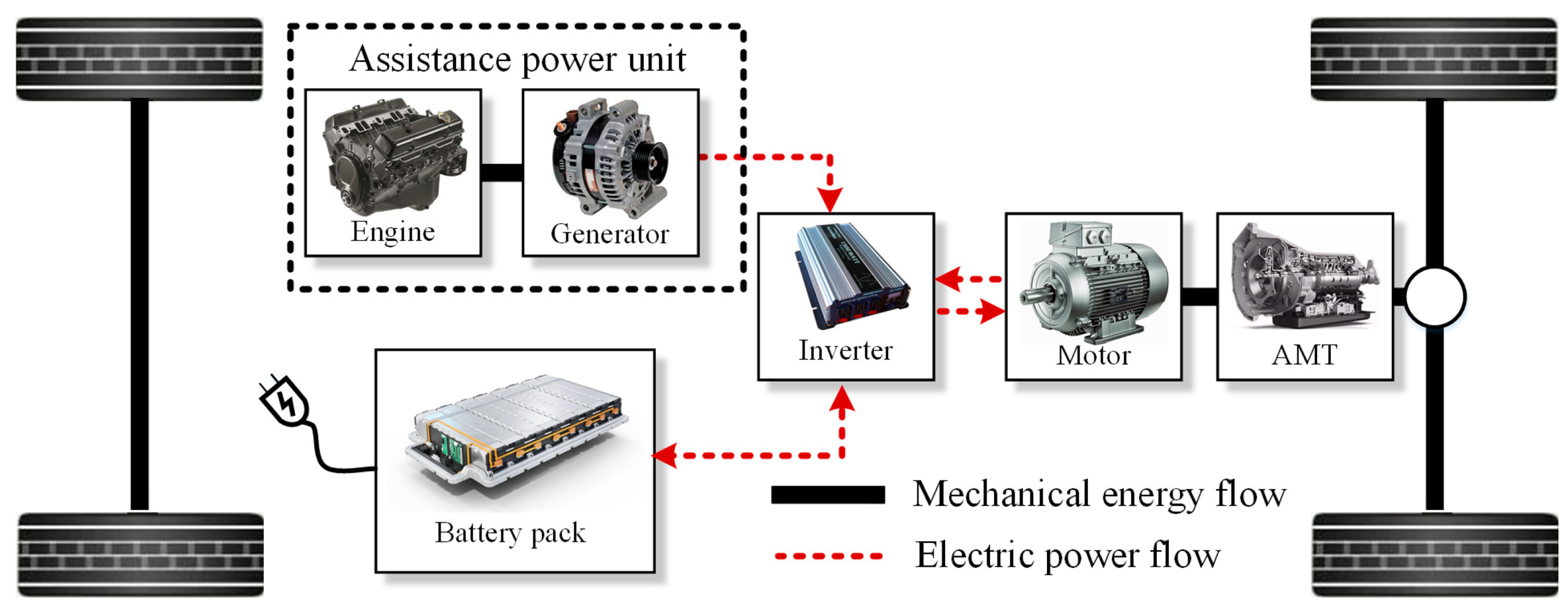
Table 1.
Indicative accidents with electric cars and ways to deal with them [20,21,22,23,24,25,26,27,28,29,30,31].
| Incident | Cause | Response |
|---|---|---|
| On passage from Oslo to Copenhagen, 2010 | Fire during charging due to a short circuit in the plug of an extension cord for charging. | Extinguishing the fire lasted two hours with continuous water sprayed from the vehicle deck, drenching the system and firefighters. |
| Woodside, California, USA 2012 | Fire in the fan caused from internal fault and overheating. | Aggressive quenching of the fire performed safely with large quantities of fresh water. The driver escaped in time and notified first the manufacturer and the Fire Department. The fire was extinguished safely. |
| 2012 | Fire due to Li-Ion battery overheating | The vehicles were left to burn, as there were no passengers inside. |
| Newark, New Jersey, USA 2012 | Fire due to vehicle’s immersion in salt water (sea). The salt water penetrated the electrical system and the high-voltage circuit, resulting in corrosion of the battery pack. | The vehicles were left to burn as the area was flooded. |
| Kent, Washington, USA 2013 | Fire due to high-speed collision and battery pack explosion. | Firefighters extinguished the fire initially by drilling holes in the top of the protective metal plate of the battery. Then, they made a hole to pour water directly into the battery compartment. The holes nevertheless spread the fire. The vehicle safety systems were activated, warning the driver to leave the vehicle unharmed. |
| Norway, 2016 | Fire during charging, due to short circuit in the vehicle’s distribution box. | The fire spread slowly, and the owner had time to disconnect the car and recover his belongings. |
| Biarritz, France, 2016 | Fire caused by technical failure, destruction of the vehicle. | Firefighters arrived in time to put out the fire, but the vehicle was burned. Because it was a technical test, the vehicle was abandoned by the passengers and the driver to burn on its own. |
| Bangkok, Thailand 2018 | Fire during home charging. | The firefighters needed 30 min to extinguish the fire and bring it under control. The car was destroyed. |
| Davie, Florida, USA 2019 | Fire due to high-speed collision with a tree. | The car caught fire after the crash and reignited after the vehicle had been removed from the scene and placed on a police trailer with flat body. There was continuous ignition of the battery pack, so aggressive fire extinguishing efforts were required. |
| Port Moody, Canada, 2019 | Fire after boat towing and penetration of salt water. | After the vehicle was removed from the water, it was drained and placed on a flatbed tow truck. Extinguishing the fire took a few hours. |
| Daegu, South Korea 2020 | Fire because the vehicle was fully charged. | Fire extinguished using continuous spray of water. |
Table 2.
Specifications of power batteries in EVs through the years.
| EVs | Energy Capacity through Years (kWh) | Voltage (Volts) | Reference |
|---|---|---|---|
| Tesla Model S | 60/70/75/85/90/100 | 375 | [45,46,47,48] |
| Mitsubishi iMiEV | 10.5/16 | 330 | [49,50] |
| Ford Focus Electric | 23/33.5 | 318.2 (max. 325) | [51,52,53] |
| Nissan Leaf | 24/30/40/62 | 360 | [54,55] |
| Renault Zoe | 22/41/52 | 400 | [56,57,58] |
| BMW i3 | 18.8/27.2/42.2 | 352 | [59,60,61] |
| Toyota Prius Plug-in Hybrid | 1.3/1.8/4.4/8.8 | 273.6 | [62,63,64,65] |
| Kia Optima Plug-in Hybrid | 9.8 | 360 | [66,67] |
| Renault Kangoo ZE | 13.2/22/33 | 400 | [68,69] |
Table 3.
Generations of plug-in electric vehicle (PEV) grid interactions [82].
Table 3.
Generations of plug-in electric vehicle (PEV) grid interactions [82].
| PEV Generation | Characteristics |
|---|---|
| 1st Generation | Available today. Grid-to-vehicle (G2V) or vehicle-to-grid (V2G) flow with the integration of modest communication capabilities enabling diagnostics. |
| 2nd Generation | Available today. Grid-to-vehicle improved with more communication capabilities (power line communications, ZigBee wireless communications, IEEE 802.11 Wi-Fi wireless communications). |
| 3rd Generation | Available today. Vehicles with two-way power flow capabilities with ultra-fast, high-capacity interfaces. Currently available are the vehicle-to–load and vehicle-to-home capabilities, whereas the electric vehicle can be used with net-metering capabilities. |
| 4th Generation | Will be used in the future. The vehicle can be used as a source for grid ancillary services (grid feeder backup) or peak power sales back to the grid (grid feeder). |
Table 4.
Motors specifications through the years.
| Model | Peak Power through Years (kW) | Peak Torque through Years (Nm) | Reference |
|---|---|---|---|
| Tesla Model S | 270/310/345/375/439/760 | 441/601/1248/1420 | [48,115,116,117,118,119] |
| Tesla Model 3 | 208/211/258/340 | 450/510/639 | [120,121,122,123] |
| Toyota Prius | 103/146/164 | 142 | [124,125,126,127] |
| Honda Accord Plug-in Hybrid | 124/135 | 306/315 | [128,129,130] |
| Chevrolet Volt | 55/87/111/120 | 320/370 | [131,132,133] |
| Chevrolet Bolt | 150 | 360 | [134] |
| Nissan Leaf | 80/110/160 | 280/320 | [135,136,137,138] |
| Toyota Camry | 88/155 | 221/270 | [139,140] |
| BMW i3 | 125/137 | 250/270 | [59,141,142] |
Table 5.
Hydrogen fuel cell electric vehicles.
| Model | Fuel Cell Output Power (kW) | Hydrogen Tank Operating Pressure (MPa) | Reference |
|---|---|---|---|
| Honda Clarity Fuel Cell | 100 | - | [186,187] |
| Hyundai ix35 FCEV | 100 | 70 | [188,189] |
| Toyota Mirai FCEV | 114/136 | 70 | [190,191,192,193] |
| Hyundai Tucson Fuel Cell | 100 | 70 | [194,195] |
| Honda FCX Clarity | 60/86/100 | 35 | [196] |
| GM HydroGen3 | 94 | 70 | [197] |
| GM HydroGen4 | 93 | 70 | [198,199] |
| Year | Equipment |
|---|---|
| 1980s | Driving assistance cameras and micro-processing modules to detect objects. |
| 1990s | In addition to cameras, radars appeared along with thermal imaging cameras for better navigation. |
| 2000s | Besides cameras and radars, lidars appeared. |
| 2010s | Autopilot and applications helping with navigation. |
Disclaimer/Publisher’s Note: The statements, opinions and data contained in all publications are solely those of the individual author(s) and contributor(s) and not of MDPI and/or the editor(s). MDPI and/or the editor(s) disclaim responsibility for any injury to people or property resulting from any ideas, methods, instructions or products referred to in the content. |
© 2023 by the authors. Licensee MDPI, Basel, Switzerland. This article is an open access article distributed under the terms and conditions of the Creative Commons Attribution (CC BY) license (https://creativecommons.org/licenses/by/4.0/).
Share and Cite
MDPI and ACS Style
Katis, C.; Karlis, A. Evolution of Equipment in Electromobility and Autonomous Driving Regarding Safety Issues. Energies 2023, 16, 1271. https://doi.org/10.3390/en16031271
AMA Style
Katis C, Karlis A. Evolution of Equipment in Electromobility and Autonomous Driving Regarding Safety Issues. Energies. 2023; 16(3):1271. https://doi.org/10.3390/en16031271
Chicago/Turabian StyleKatis, Christodoulos, and Athanasios Karlis. 2023. "Evolution of Equipment in Electromobility and Autonomous Driving Regarding Safety Issues" Energies 16, no. 3: 1271. https://doi.org/10.3390/en16031271
Note that from the first issue of 2016, this journal uses article numbers instead of page numbers. See further details here.