
SWOT Analysis of Non-Technical and Technical Measures towards “(Nearly) Zero-Emission Stove Technologies”
1
University of Applied Sciences Wiener Neustadt GmbH, 2700 Wiener Neustadt, Austria
2
BEST—Bioenergy and Sustainable Technologies GmbH, 8010 Graz, Austria
*
Author to whom correspondence should be addressed.
Energies 2023, 16(3), 1388; https://doi.org/10.3390/en16031388
Submission received: 15 December 2022
/
Revised: 20 January 2023
/
Accepted: 23 January 2023
/
Published: 30 January 2023
(This article belongs to the Special Issue Biomass Conversion Technologies II)
Abstract
:Firewood stoves are widespread and popular for renewable heat supply in Europe. Several new technological measures have been developed recently that aim at improving the appliance performance in terms of emissions and efficiency. In order to support the trend towards “(nearly) zero-emissions technologies”, the objective of this study was to provide a profound overview of the most relevant technical primary and secondary measures for emission reduction and to analyze their functionality, the relevant framework conditions for their application and their costs. Since user behavior is essential for emission and efficiency performance, the state of knowledge about user behavior is summarized and the latest measures for its optimization are evaluated as non-technical primary measures. Primary and secondary measures were analyzed separately, but also potentially promising combinations of primary and secondary optimization were evaluated using SWOT analysis. The results showed that complementary application of primary and secondary measures will be necessary in order to achieve “(nearly) zero-emission technologies”. The paper is useful for manufacturers and provides them with guidance and recommendations for future developments. They can specifically select appropriate measures for their products and applications not only based on technical aspects, but also with a strong focus on user behavior and user comfort.
1. Introduction
Firewood stoves, i.e., room heaters or chimney stoves, cookers, fireplaces/insets and slow heat release appliances or tiled stoves are widespread and popular for renewable heat supply in Europe (Figure 1) [1].
The stock of firewood room-heating appliances in Europe is about 65 million appliances and annual sales are about 2.4 million devices [1]. Assuming an average product price of €2000, as proposed by [1], the annual sales volume is about €4.8 billion.
Using firewood in stoves is not only linked to heat supply, but is also strongly associated with basic and emotional needs, for example, covering people’s needs for energy security in case of crises, coziness, stress reduction and “cozy fire making” for get-togethers with family or friends [2]. However, residential wood combustion using firewood stoves is also regarded as a significant source of harmful gaseous and particulate emissions [3]. One solution to avoid the emissions of manual firewood heating would be the prohibition of stove technologies. In several European countries, e.g., Germany, Switzerland or Italy, there are already regional bans on firewood stoves [4]. However, bans on wood stoves are often linked with great opposition from the population since, as mentioned before, wood combustion is associated with several basic and emotional needs [5]. Consequently, in the future, the best solution would be to find possibilities that meet the requirements of minimal emissions as well as the various basic and emotional needs that people link with manual firewood combustion.
Since the beginning of 2022, general requirements regarding maximum emissions and minimum efficiency performance have come into force within the European Union [6], and it can be expected that emission requirements will become even more stringent in the upcoming years. Therefore, several manufacturers are considering measures and technologies in order to achieve “(nearly) zero-emissions technologies” in the near future.
An important non-technical approach to improve the real-life operating performance of stoves is the optimization of user behavior, which is known as a crucial factor influencing emissions in real-life operation [7,8]. However, several new technological measures have also been developed recently that aim to improve appliance performance in terms of emissions and efficiency.
In order to support the trend towards “(nearly) zero-emissions technologies”, the objective of this study was to provide a profound overview of the most relevant technical and non-technical primary measures as well as secondary measures for emission reduction, and to analyze their functionality, relevant framework conditions for their application, costs and user comfort. Additionally, potential synergetic effects of the combination of primary and secondary measures as well as synergies of different technical measures with user comfort were evaluated in order to provide guidance and recommendations for future developments.
This study represents the extended version of the conference paper for the European Biomass Conference & Exhibition 2022 with the title “SWOT-Analysis of Primary and Secondary Measures for Firewood Stoves” [9]. In the following article, primary measures are categorized by technical and non-technical forms. User behavior aspects and their optimization as important limiting factors for “(nearly) zero technologies” are included in the evaluation. User behavior is characterized by several aspects of heating operation, which can be decided or influenced by end-users and which can significantly affect emission and efficiency performance, i.e., fuel selection, number of firewood pieces per batch, total batch mass of fuel, ignition technique used, time of recharging and adaptions of combustion air supply settings (if not automatically regulated) [7,8,10,11,12,13]. Hence, user behavior and its potential for optimization are analyzed as non-technical primary measures because of the importance of user behavior to achieve “(nearly) zero emissions technologies”.
2. Material and Methods
A comprehensive literature review was carried out in order to identify the most relevant primary and secondary measures as well as typical aspects of user behavior. All primary and secondary measures were analyzed regarding functionality, efficiency, framework conditions, cost (or price) and user comfort.
The classification of specific measures either as primary or secondary was carried out using the following approach.
2.1. Primary Measures (Emissions Prevention)
All measures, technologies or systems that aim to prevent emissions were classified as primary measures, i.e., measures aimed at optimized combustion conditions in order to avoid the formation and release of emissions from incomplete combustion, namely, carbon monoxide (CO), volatile organic compounds (VOC) and particulate organic matter, as well as soot emissions (part of total particulate emissions, PM emissions) downstream from the (main) combustion chamber. Primary measures are classified as technical and non-technical forms. Technical primary measures are linked with the room-heating appliance itself and are implemented as technical solutions, e.g., by construction, materials used or specific technical devices, whereas measures for optimization of user behavior are classified as non-technical primary measures.
2.1.1. Non-Technical Primary Measures
The following primary measures were analyzed and evaluated as non-technical-primary measures:
- General information about “correct heating”;
- Hands-on user training;
- Quick User Guide (QUG).
2.1.2. Technical Primary Measures
The following primary measures were analyzed and evaluated as technical-primary measures:
- Air supply and air staging concept;
- Combustion chamber design;
- Draught control and automatic combustion air regulation devices;
- Alternative (or advanced) combustion concepts.
2.2. Secondary Measures (Emissions Reduction)
All measures, technologies or systems that aim to reduce emissions downstream from the (main) combustion chamber were classified as secondary measures. The following secondary measures were analyzed and evaluated:
- Packing technology (oxidizing reactors);
- Catalysts;
- Foamed ceramics (non-catalytic);
- Fabric baghouse filters;
- Electrostatic precipitators (ESP).
Secondary measures or technologies can be further classified as integrated or retrofitted applications. Integrated technologies are located within the appliance (e.g., a post-combustion chamber), whereas retrofitted technologies are located downstream in the flue outlet of the appliance, e.g., within the chimney system.
2.3. SWOT Analysis
Using SWOT analysis, primary and secondary measures were evaluated and discussed regarding strengths, weaknesses, opportunities and threats. Furthermore, potential combinations of primary and secondary measures as well as synergetic effects were analyzed and discussed.
3. Results
3.1. State of Knowledge about User Behavior
Firewood heating using stoves is traditionally a manual operation. This means that in contrast to automatic combustion technologies, users have to decide on many operating parameters that are important for thermal heat output, as well as high efficiency and low emissions. In the following, the respective parameters are described and evaluated regarding their impact on emissions and efficiency. Furthermore, based on users surveys, typical operating habits when handling the respective parameters are analyzed.
3.1.1. Selection of Firewood
According to user surveys, hardwood, e.g., beech (Fagus sylvatica), is predominantly used. However, softwood, e.g., spruce (Picea abies), or briquettes are also selected by users [11,12]. The use of illegal fuels, e.g., waste wood, seems to be uncommon, but can occur sporadically [12,14]. Regarding the impact of the type of wood on emissions, e.g., hardwood or softwood, there are measurement results that reveal a potential impact [15], but also publications that indicate no general correlation of the type of wood with emission levels [16,17]. Dimensions of firewood as well as moisture content were found to be the most important parameters regarding emissions [18]. According to experimental evaluation, oversized and very small pieces of firewood correlate with increased emission levels. Further, a moisture content above 20% results in significantly increased CO and VOC emissions [19]. In order to guarantee a moisture content in the range of about 15–20%, technical drying or a storage duration of at least 4–6 months under specific storage conditions, i.e., covered and permeable to air, is necessary [20,21]. According to the findings of user surveys, the average storage duration of firewood is significantly longer than 6 months [11], which indicates a water content of firewood used in real life below 20%. This was also confirmed by exemplary field measurements, which revealed an average moisture content of 12% and a range of moisture content of 8% to 21% [22].
3.1.2. Ignition Technique
The ignition technique at the beginning of a heating operation is regarded as essential in terms of gaseous and particulate emissions. In principle, two modes can be differentiated as potential ignition techniques:
- Bottom-up ignition technique
- Top-down ignition technique
Using the bottom-up ignition technique means placement as well as lighting of the starting aid at the bottom of the fuel batch. The lower fuel layers are small pieces of kindling material. Above the kindling material, larger firewood pieces are located. In contrast, top-down ignition is characterized by the placing of larger firewood pieces directly on the grate with the kindling material above. The specific starting aid, which is placed on top of kindling material, is lit and the fuel batch combusts gradually from the top downwards. Starting aids for both ignition techniques can be either paper or preferably specific starting aids, e.g., waxed wood wool.
The arrangement of fuel is typically cross-joint for both ignition techniques. For the bottom-up ignition technique, the traditional campfire arrangement is also widespread (Figure 2) [10,11,23].
Former combustion tests comparing both ignition techniques indicated clear advantages of top-down compared to bottom-up ignition techniques, since around 50% to 80% fewer particulate emissions were measured [24]. Consequently, general information for end-users about “correct heating” favors principally the top-down ignition technique. However, the latest combustion experiments revealed that top-down ignition may not be the best solution for every appliance, since comparative combustion tests showed better performance for the bottom-up ignition technique compared to the top-down ignition technique (Table 1).
Consequently, the current state of knowledge indicates no general suggestion for one of either ignition techniques, but reveals the need for an appliance-specific identification of the “best-practice” ignition technique for each appliance [7,10]. Furthermore, comparative combustion tests under natural and constant controlled draught conditions have shown that higher draught conditions at the beginning of heating operation are beneficial regarding emission performance during the ignition procedure. Hence, ignition of the first fuel batch supported by a ventilator would be a potential measure to reduce the emissions of the ignition process [7,8].
3.1.3. Time of Recharging
In real-life operation, users recharge a new fuel batch either when the flames are gone or when only a few flames are still visible [11,12]. In principle, this habit corresponds with general recommendations about “correct heating” and was also confirmed as the best time for recharging during comparative combustion tests [7]. In cases of recharging too late, i.e., when the flames have already been gone for a longer time and the stove as well as the firebed have already cooled down, smoldering combustion conditions occur, which are linked to significantly increased gaseous and particulate emissions [7,8].
3.1.4. Batch Mass of Fuel
The mass of the fuel batch depends on the number and size of firewood pieces used. Comparative combustion experiments showed that using only one firewood piece instead of two to four pieces is correlated with increased gaseous (CO VOC) and particulate (PM) emissions, as well as reduced thermal efficiency [18,19]. Furthermore, general information about “correct heating” does not recommend the use of single firewood pieces for recharging [21]. However, an overload of the combustion chamber by using too many firewood pieces and a too-high total fuel mass is correlated with increased gaseous and particulate emissions [18,19].
According to user surveys, the number of firewood pieces used for one fuel batch depends on the type of technology of room-heating appliance used. Specifically, users of chimney stoves and biomass cookers typically use two or three firewood pieces per batch, whereas users of tiled stoves typically use more than three pieces per batch [11,12]. This difference is explainable by the type of technology utilized, since tiled stoves feature a high mass for heat accumulation and are therefore operated with low batch numbers, but high batch masses. According to surveys, incorrect user behavior in respect of using only one piece of firewood for recharging or overloading the appliance with too much firewood is not common, but was indicated in sporadic cases [11].
3.1.5. Positioning of Firewood in the Combustion Chamber
The positioning of firewood pieces in the combustion chamber can be performed either in parallel or vertically to the combustion chamber door. The placement of firewood in a vertical mode either in the campfire arrangement or leaned against the combustion chamber walls, e.g., for oversized firewood pieces, is also possible. Depending on the design of the combustion air supply, different variations of positioning of firewood pieces are either beneficial or adverse regarding minimal emissions [8].
Consequently, specific general conclusions and recommendations that cover the wide range of technologies and designs are not possible, and the best-practice procedure regarding positioning the firewood in the combustion chamber must be defined for specific appliances. However, general findings suggest using at least two pieces of firewood, which should be located in the rear space of the combustion chamber with only a small distance between them and without direct contact with the combustion chamber walls. Furthermore, firewood should be placed on the firebed with the side covered by bark facing downwards [8,21].
3.1.6. Air Valve Settings
Traditionally, air valve settings are adjusted manually by stove users using one or several mechanical valves. Air valve settings significantly affect the combustion conditions and therefore have an impact on the ignition of the wood after recharging or on burn rates [7,8]. The correct air valve settings for different combustion conditions, e.g., ignition batch, recharging and different load settings are defined in the manual. An important aspect regarding air valve settings is in the stand-by phases of the stove. After finishing a heating operation and during stand-by phases, air valve settings should be closed in order to achieve high thermal efficiencies as well as to avoid thermal heat losses via the chimney [25,26]. About one third of users surveyed declared that they do not adjust air valve settings during operation and about 50% of users surveyed stated that they adjust air valve settings only once during each batch [11,12]. Closing the air valve settings after finishing a heating operation is carried out only by about 50% of surveyed stove users [11].
3.1.7. Number of Batches
The number of batches used during one heating operation cycle, i.e., from the start of the ignition batch until flames are gone after finishing recharging, varies during the course of the year and depends also on the type of technology used. For example, stove technologies with a high heat storage capacity and a long duration of thermal heat release after finishing a heating operation, i.e., tiled stoves or slow heat release appliances, are operated with fewer batches, whereas chimney stoves or insets with a comparatively low heat storage capacity are operated with more batches, since thermal heat release is directly correlated with the number of batches [12].
3.2. State of the Art of Non-Technical Primary Measeurs
Based on the analyzed parameters of user behavior in correlation with the information of the user surveys and comparative experimental combustion experiments, it is obvious that there still is significant optimization potential regarding best-practice heating operation of stoves. In different R&D projects, three potential measures for optimization of user behavior in real life operations were developed; their effectiveness was also, at least to some extent, evaluated and demonstrated by experimental tests in the field:
- General information about “correct heating”;
- Hands-on user training;
- Quick User Guide (QUG).
3.2.1. General Information about “Correct Heating”
The correct heating operation mode is principally specified in the manual. One question in both surveys was about the attention users pay to the manual and if they operate their appliances according to the specifications given in the manual. According to the survey results, about 50% of users read the manual and stated that they operate their stoves, at least to some extent, according to the specifications of the manual. The highest share of users who stated that they operate their stoves according to the manual were users of tiled stoves (50% [11]; 79% [12]). However, the results revealed that there is a percentage of users who either did not respond to the question or declared that they had not read the manual (about 10% of users). Further, there was also a proportion of about 30% of respondents who admitted that they operate their stoves in their own way and explicitly not according to the manual [11,12]. User surveys confirmed that information in manuals does not reach all users or is not taken seriously by a proportion of users. Therefore, it is assumed that there is a great lack of knowledge in a remarkable quantity of users about “correct heating” with firewood room-heating appliances and about its importance for the environment.
“General information about correct heating” aims to reach as many users as possible, including those who commonly do not read the manual, in order to guarantee a broad information level about the importance of correct heating for the environment, i.e., less pollution, as well as direct benefits for users, e.g., less malodor, less firewood demand and less impurities on combustion chamber windows.
General information about “correct heating” is provided via leaflets [27,28], videos [29] or webpages [30]. The information is published by R&D institutes, stove associations, local authorities or manufacturers and commercial enterprises. Therefore, the advantage of this measure is that users have the possibility to appraise the topic “correct heating” on a broad but also low-threshold level and to scrutinize their own habits and possibly change behavior patterns. The disadvantage of this measure is that general information cannot deal with the broad variety of firewood room-heating appliances as well as appliance-specific requirements. In the worst-case, general information about “correct heating” even contradicts appliance-specific best-practice heating operations, e.g., if bottom-up ignition technique is more advantageous compared to top-down ignition technique for the relevant appliance.
According to the knowledge of the authors, there are no empirical evaluations available that set out to quantify the benefits and impacts of campaigns regarding general information about “correct heating”. Additionally, potential costs for such campaigns, which cover both personal costs as well as material costs, are not available. An interesting figure would be the total costs in relation to the respective country or in correlation to the stock or number of appliances sold.
3.2.2. Hands-On User Training
The approach and effects of providing hands-on user training in the field was demonstrated in the Austrian R&D project CleanAir [31]. Two test series of field testing were carried out using stoves of volunteer end-users. In the first test series, four stoves (three chimney stoves, one tiled stove) were measured during operation by users according to their own habits. Subsequently, mentoring was carried out by the experts, who performed the measurements in order to improve user behavior. Typical optimization measures were the change of the ignition technique, i.e., top-down instead of bottom-up ignition techniques, utilization of professional starting aids instead of paper or cardboard and optimization of combustion air valve settings in order to avoid phases of deficiency of combustion air correlated with smoldering conditions [32]. Based on the mentoring and optimization measures, PM emissions were reduced by about 50% in the second test series. Moreover, health-relevant PAH emissions, illustrated by benzo(a)pyrene emissions (BaP), were reduced significantly (Figure 3).
Besides the aforementioned hands-on user training in people’s homes, a second approach of hands-on user training was carried out in the CleanAir project [33]. A mobile trailer equipped with three stoves as well as measurement and monitoring devices was used for public workshops [33]. During the workshops, users were able to demonstrate their heating operation habits on the different stoves whilst simultaneously receiving feedback from the visualized measurement results and explanations from experts. Subsequently, users were able to utilize the expert tips in their own heating operations and immediately see the effects, i.e., curve of gaseous emissions, thermal efficiency. According to this citizen-science approach, the emission reduction potential of this hands-on user training was calculated to be 60% for PM, 75% for CO and VOC and more than 95% for BaP emissions [33].
In conclusion, the costs and exertion required for hands-on user training is significant. An advantage of hands-on user training is the direct contact between users and experts, offering the possibility for users to raise questions, discuss and receive feedback. Furthermore, the optimization potential of implemented changes in user behavior are transparent and quantifiable. However, the reliability of positive long-term effects of hands-on user training is still not validated.
3.2.3. Quick User Guide (QUG)
A standardized and short piece of user information, the so-called QUG, was developed by the European R&D project “beReal“ [34]. The principle of the QUG is to inform users about the appliance-specific best-practice heating operations in one DinA4 page. [35]. Such heating operations are structured in four parts:
- Preparation and ignition;
- Recharging at nominal load;
- Recharging at part load;
- Finishing heating operation.
For each part, the best-practice user behavior for the relevant appliance is described and illustrated by pictures, i.e., the ignition technique, number of firewood pieces for recharging, batch mass for nominal and partial load and air valve settings for different phases.
The effectiveness of the QUG on emissions and thermal efficiency was evaluated based on field measurements using 13 commercial chimney stoves [36]. In a first measurement campaign, users operated the stoves according to their own habits followed by a second measurement campaign where the users operated the stoves according to the QUG for each appliance. The results showed a smaller range of emissions (CO, VOC, PM) and lower average PM emissions. The average thermal efficiency of the 13 appliances increased by 0.4% (absolutely). However, there were still some cases where emissions were lower when following users’ own habits compared to the operation according to the QUG [36]. This reveals the challenge for manufacturers to identify appliance-specific best-practice user behavior linked with efforts of experimental analysis in the laboratory. Furthermore, it is not possible to consider manifold installation conditions at the end user, e.g., chimney system, connecting flue gas pipe, draught dampers, etc., in detail in the lab; however, these still have an impact on real-life operations.
3.3. State of the Art of Technical Primary Measures
Technical primary measures aim to optimize combustion conditions. Basically, primary measures depend on the application of the so-called 3T principles, which enhance complete combustion [37]:
- Time—sufficient residence time of intermediate combustion gas species within the hot combustion zone of the combustion chamber;
- Temperature—sufficient temperatures in the combustion chamber in order to enhance oxidation mechanisms;
- Turbulence—sufficient mixture of intermediate combustion gases with combustion air.
Challenging factors for the best possible application of the 3T principles are the high share of transient phases during batch-wise combustion, as well as cold start and cooling-down conditions at the beginning and end of heating operations. Furthermore, it is necessary to consider that local conditions may differ within the combustion chamber and that the operation by the user, e.g., operating errors, may have an important impact on combustion quality [7,8].
3.3.1. Air Supply and Air Staging Concept
The most important precondition for complete combustion is a sufficient supply of air in the combustion zone. The minimal amount of combustion air supply is determinable by combustion calculations. An important indicator for the evaluation of combustion air supply is the air excess ratio, i.e., the lambda value (λ) [37].
The lambda value represents the ratio of minimum combustion air () for complete combustion in relation to actual supplied combustion air () (Equation (1)). Consequently, a lambda value of 1 is necessary to enable—at least theoretically—complete combustion. In practice, the lambda value is >1 since perfect turbulence is unachievable, plus combustion conditions differ locally as well as along batch durations. Based on residual oxygen (O2) measurements of flue gases, the excess air ratio is approximatively derivable (Equation (2)).
Low emissions (CO, VOC) and high efficiency (𝜂th) of a combustion batch correlate with low lambda values and indicate good primary combustion conditions.
Modern stoves are typically room-sealed appliances and therefore feature a central combustion air suction pipe (Figure 4). Hence, it is possible to cover the combustion air demand without air from the installation space, which is important to avoid under pressure in the living room and to guarantee safe operation. This, as well as controlled ventilation, is an important precondition for the utilization of stoves, especially in modern airtight buildings.
Besides the actual combustion air supply, optimal air staging is also important. This means the distribution of the actual combustion air supply within the combustion chamber as primary and secondary air. Primary air supply enhances gasification processes, whereas secondary air supply enables the complete oxidation of gaseous intermediate compounds. Primary air should enter the combustion chamber without previous preheating, whereas preheating of the secondary air supply is recommended [38]. Window purge air is supplied for stoves featuring a window, in order to keep the window clean of soot and tar. Window purge air is mostly part of the secondary air supply but may also to some extent act as primary air. Frequently, either window purge air or the secondary air supply is specified or defined as tertiary air supply.
The identification of an optimal amount and distribution of combustion air supply as primary, secondary and tertiary air represents an important primary measure. On the one hand, different operating phases of batch-wise combustion have to be considered but, on the other hand, different load settings also have a relevant impact. If combustion air supply is manually adjusted, the different partial volume flows are either separately adjustable by different air dumpers or one air dumper affects several partial volume flows.
Air staging is further relevant to influence the turbulence within the combustion chamber. The dimensioning of secondary air nozzles is especially important to achieve a good mixing of combustion air with the intermediate combustion compounds. Basically, major cross-sections of secondary air nozzles have a higher impulse effect and therefore enter more deeply into the combustion chamber [39].
The development and implementation of an air staging concept can be carried out either by using a trial-and-error approach or by application of specific software tools, e.g., Computational Fluid Dynamics (CFD) [40]. The utilization of CFD software is advantageous, since fewer experiments may be necessary during the development process. On the other hand, it has to be considered that high shares of transient conditions of batch-wise combustion are still challenging and part of recent R&D projects [41]. Therefore, a combination of experimental development supported by CFD application is recommended.
For the development and implementation of an air staging concept, there are no remarkable material costs. However, personal costs for experiments and potential license fees for CFD software may be considerable. Hence, it is important to transfer general findings and solutions concerning the developed air staging concepts to different stove models in order to keep development costs at an acceptable level.
3.3.2. Combustion Chamber Design
Dimensioning and selection of appropriate materials for combustion chamber design represent an effective primary measure. High and slim combustion chambers are more beneficial for homogeneous residence times as well as temperature profiles. The materials used for combustion chamber design should be incombustible, such as fireclay or vermiculite in combination with thermal insulation. Between the insulating layer and the stove casing, a small air gap is recommended [38,42].
Furthermore, the windows of combustion chambers should have moderate sizes to avoid large amounts of radiation losses, which result in reduced temperatures inside the combustion chamber. Other possibilities to reduce radiation losses via the window are the use of double- or triple-glazed windows or specially coated windows [38,42].
Downstream, the main combustion chamber flue gases should pass a post-combustion chamber made up of one or more vermiculite or fireclay baffle plates. For slow heat release appliances or tiled stoves, the flue gases pass the heating flues of the heat accumulator. For the combustion chamber design of tiled stoves, specific instructions for standardized combustion chamber designs in relation to specific nominal thermal loads (batch mass of firewood) are available, e.g., the Austrian “UmweltPlus” combustion chamber [43].
The avoidance of short-circuiting of the flue gases within the stove and leakage streams of false air due to leakages in the stove casing or sealings represent another important design aspect and primary measure. For room-sealed appliances, the air-tightness of the appliance is evaluated by a specific procedure measuring the leakage rates of the stove with sealed combustion air inlets and flue gas outlets. According to this procedure, certain limits of the leakage rate shall be not exceeded, e.g., 3 m³(STP)/h at 10 Pa static overpressure according to EN 16510-1 [44].
3.3.3. Draught Control and Automatic Combustion Air Regulation Devices
Besides the air staging concept, i.e., the design of primary and secondary air nozzles, the flue gas draught has a significant impact on the combustion air supply. Flue gas draught conditions mainly depend on the chimney system, i.e., chimney height, temperature and weather conditions. Experimental lab tests under constantly controlled draught conditions at 12 Pa, 24 Pa and 48 Pa demonstrated that gaseous emissions (CO, VOC) can either increase or decrease at higher draught levels. In contrast, results revealed no significant effect on PM emissions. However, a significant correlation between decreased thermal efficiency and increased burn rate at higher draught conditions was observed [10].
Consequently, draught control devices represent an efficient measure to enable high thermal efficiencies independently from chimney systems or weather conditions. Draught control devices are either integrated within the chimney system or installed in the connecting flue gas pipe of the stove to the chimney. As shown in Figure 5, for example, they are equipped with flexible dampers that are shifted at increased underpressure or draught levels.
The cost for external draught control devices is about €300 [25].
Experimental tests carried out under natural draught conditions confirmed the beneficial effect of external draught control devices on thermal efficiency. According to specific experiments using a chimney stove, thermal efficiency increased absolutely by 9.9%, i.e., from 49.2% to 59.1% thermal efficiency [25].
For some stove models, e.g., slow-heat-release appliances/tiled stoves built on-site, chimney specifics and resulting draught conditions are typically taken into consideration by software programs for the design of the stoves at the homes of end-users [46]. However, during heating operations, increased draught conditions may also occur with negative effects on air staging concepts and thermal efficiency performance. Hence, draught control devices are beneficial as well. Furthermore, draught control devices can be used to enhance the cooling-down of the chimney system after a heating operation, resulting in reduced standby-losses of the appliance.
As illustrated by Figure 6, batch-wise combustion is characterized by different phases, i.e., the start-up phase (1), main burning phase (2), and burn-out phase (3). For each of these phases, the share of primary and secondary air demand is different. During the start-up phase, sufficient primary and secondary air supply is necessary for a fast ignition of the fuel batch, whereas during the main burning phase, primary air supply should be significantly reduced. During the burn-out phase, oxidation of carbon/coke dominates, which requires a predominantly primary air supply, with significantly less secondary air.
The manual adjustment of the previously mentioned air supply pattern requires adapting primary and secondary air supplies separately according to “expert knowledge”. Furthermore, this procedure requires comparatively high operating efforts, which are frequently not carried out by typical end-users [11,12].
In order to guarantee an optimal combustion air supply during each combustion phase, either integrated or retrofitted automatic combustion air supply regulation devices are available. Such devices aim to adjust fast ignition phases with minimal emission peaks, enhancing main burning phases and optimizing burn-out phases with high temperatures and minimal residual oxygen (Figure 7) [48].
Basically, automatic combustion air regulation devices feature dampers that are electrically controlled by an actuator based on temperature monitoring within the combustion chamber. Further, the control concept utilizes the sensor signals, indicating the opening of the combustion chamber door, e.g., for recharging a new fuel batch. Optical signals such as LEDs or a display are often used by the system to communicate with users, e.g., indicating the optimal time for recharging. The following list provides an overview of selected, commercially available automatic combustion air regulation devices [49]:
- Brunner EAS und EOS;
- Buderus Logamatic TCA200;
- DROOFF fire+;
- Olsberg Efficiency Controller (OEC);
- RIKA Rikatronic3;
- Schmid Multi-Regelung (SMR);
- SPARTHERM SEO.
In addition to an optimization of efficiency and emission performance, well-adapted retrofitted or integrated automatic combustion air regulation devices may enhance the user comfort and support correct heating operations. Furthermore, users may operate their stoves on a reduced load setting more easily by fueling a smaller fuel batch and selecting the reduced load mode on the automatic combustion air regulation device.
For slow-heat-release appliances/tiled stoves, electrically controlled air dampers of combustion air supply systems for automatic opening (starting the heating operation) and closing (finishing the heating operation) are often available. However, the stepwise regulation of combustion air supply during a heating operation is often not a standardized procedure. In such cases, a system upgrade by implementing additional sensors or even only a control algorithm represents an efficient optimization measure with comparatively low additional costs, since most of the hardware is already fitted.
MACK et al. (2018) evaluated the effect of an automatic combustion air regulation device on emissions and thermal efficiency using a chimney stove [25]. According to their results, reduced gaseous emissions and increased thermal efficiency were observed (4.8% absolute change, i.e., from 61.5% to 66.3%). However, a reduction of PM emissions was not observed.
Regarding the question of whether either retrofitted or integrated automatic combustion air regulation devices are preferable, there are some aspects to consider:
If retrofitted systems are used, the implementation and parametrization of the system should be carried out by an expert according to flue gas measurements. An additional consideration is that the implementation of a retrofitted system might be a significant change to the whole stove system, meaning that official approval before operation, e.g., by a chimney sweep, might be necessary [25].
In contrast, such steps would be not necessary when the automatic combustion air regulation device is already integrated in the stove and therefore already evaluated as part of the stove during official type testing.
Examples of such integrated combustion air regulation systems are the WIKING® Automatic™ [50] or the HWAM® SMARTCONTROLTM [51] from Danish stove manufacturer HWAM. As illustrated in Figure 8., the model SMARTCONTROL regulates the combustion air supply during the single characteristic combustion phases of batches, not only based on flue gas temperature measurements but also on residual oxygen measurements (O2) [52,53].
3.3.4. Advanced Combustion Concepts
The selection of a particular combustion principle significantly affects the combustion process and stove design. Consequently, it must be respected for all the previously mentioned primary measures.
The differences between burn-through and top-down combustion principles are in the primary air supply. For the top-down combustion principle, primary air is supplied laterally to the fuel batch, whereas a primary air supply via the grate from the bottom of the combustion chamber characterizes the burn-through combustion principle.
In the burn-through combustion principle, the total fuel batch is heated up at the same time. Hence, there are no clearly separated combustion zones of pyrolytic degradation or gasification processes. Consequently, the appropriate location of combustion air supply in relation to the specific requirements of the thermal degradation mechanisms is challenging. The burn-through combustion principle is typical for the operation of chimney stoves using several fuel batches per heating operation cycle (batch-wise heating operation).
The top-down combustion principle is also typically utilized in batch-wise heating operation. However, due to the lateral primary air supply in combination with the top-down ignition technique [37] the ember cone moves gradually from the top downwards during the batch-combustion process. Hence, the residence times of combustion gases in the combustion chamber vary from comparatively short at the beginning to comparatively long at the end of the fuel batch. If a new fuel batch is recharged, the combustion principle corresponds to the burn-through combustion principle. The top-down combustion principle is typically used for slow-heat-release appliances/tiled stoves [37].
The bottom-up combustion principle is characterized by the conveyance of flue gases from the bottom of the combustion chamber. The ember zone does not move and a comparatively stable formation of zones for pyrolytic degradation and gasification occurs. This facilitates and enhances the targeted supply of primary air. Furthermore, no variation of residence times, as described for the top-down combustion principle, occurs.
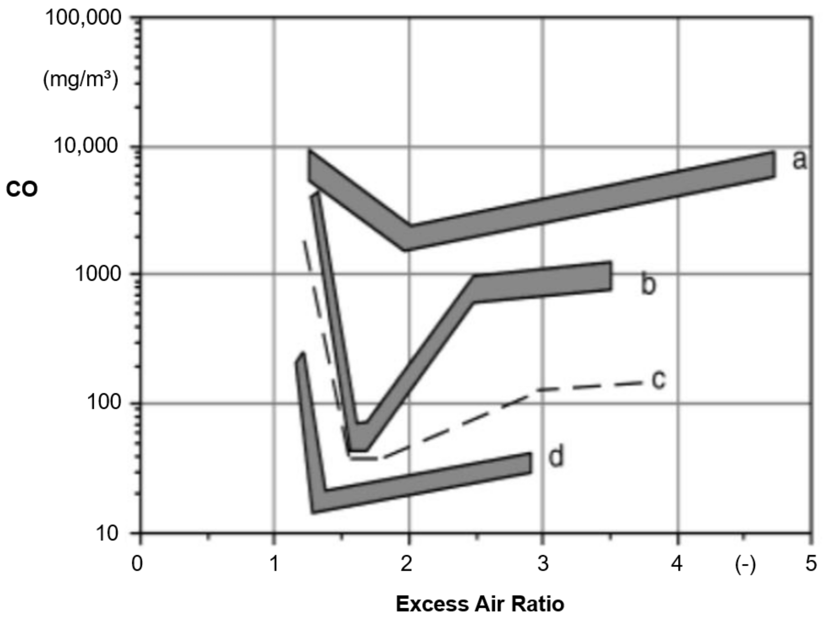
As illustrated in Figure 10, the bottom-up/downdraft combustion principle leads to significantly reduced emissions and better efficiency performance when implemented and used in automatic combustion technologies with forced air ventilation [54]. However, there are already some solutions on the market that apply the bottom-up combustion principle for stoves operated under natural draught conditions in the field. These types of appliances show low emissions and high efficiency according to official type test results (Table 2) [55]. They include:
- Xeoos-chimney stove: Twinfire;
- Attika: Type Bionic Fire.
Figure 10.
Carbon monoxide emissions as functions of lambda values for different furnace types: (a) wood stove—top-down combustion; (b) downdraft boiler; (c) automatic wood furnace; (d) advanced automatic wood furnace [54]. Reprint with permission from T. Nussbaumer, Combustion and Co-combustion of Biomass: Fundamentals, Technologies, and primary Measures for Emission Reduction, Energy & Fuels 2003, 17, 1510–1521; Copyright 2013, American Chemical Society.

Table 2.
Official type test results of stoves featuring the bottom-up combustion principle.
| Stove | Nominal Load | CO * | PM * | 𝜂 |
|---|---|---|---|---|
| Xeoos [56] | 8 kW | 0.05 vol.-% | 22 mg/m³ | 83.6% |
| Xeoos [57] | 5 kW | 0.05 vol.-% | 20 mg/m³ | 83.7% |
| Bionic Fire EVO [58] | 5 kW | 302 mg/m³ | 4 mg/m³ | 86.0% |
* STP: 0 °C, 1.013 bar; referred to 13 vol.-% O2.
To conclude, changing the combustion principle, i.e., from burn-through or top-down to a bottom-up/downdraft combustion method represents a promising and highly effective primary measure, but is also linked with significant maximum R&D efforts. All the other primary measures mentioned must be implemented or adapted in relation to the bottom-up combustion principle. The bottom-up combustion principle seems to be especially suitable for slow-heat-release appliances/tiled stoves due to typically large fuel batch amounts and no or a limited number of recharging batches [11,12].
3.4. State of the Art of Secondary Measures
Secondary measures are actions, technologies or systems that aim to reduce emissions downstream from the (main) combustion chamber. The most relevant performance indicator is the conversion efficiency () which can be evaluated by a comparison of the emissions up- (raw gas) () and downstream (clean gas) () of the secondary emission abatement technology (Equation (3)). Thereby, must be considered that conversion efficiencies might be different in relation to specific reference values, e.g., mass concentrations or particle size distribution for PM emissions [59].
3.4.1. Packing Technology (Oxidizing Reactors)
Packing technology was developed by the German Fraunhofer Institute for Building Physics (IBP). Packing technology consists of ceramic or metallic pall rings (Ø 35 mm to 50 mm) formed into so called packing modules. A packing module is integrated without any bypass between the main and post-combustion chamber and all of flue gases flow through the module (Figure 11) [60,61].
The packing technology should meet the following requirements:
- High specific heat capacity;
- Enhancement of turbulence;
- Rough surface area and adhesive material properties;
- Low flow resistance;
- High mechanical, thermal and chemical resistance.
Specific guidelines for design and dimensioning are available [33]. The most relevant design parameters are:
- Flow area loading ();
- Pressure drops (, ≤ 3Pa);
- Thermal surface loading ();
- Thermal volume loading ().
The emission conversion principle of the packing technology is based on the oxidation of combustible components that agglomerate on its surface area during operations. Additionally, enhanced turbulence and increased residence time of flue gases is achieved by the geometric structure of the packing module, also enabling better oxidation conditions (Figure 12).
Hence, integration and location of the packing module within the combustion appliance is essential in order to guarantee sufficient temperature levels. The thermal heat of the start-up and main burning phases is stored to some extent by the packing module and is released again during the burn-out phases. Therefore, temperature curves are more stable during the whole operating time and minimum temperatures are higher (Figure 13) [60].
Based on empirical lab tests, it has been shown that packing technology can reduce gaseous and particulate emissions as well as increase thermal efficiency (Table 3) [60].
The results of Table 3 reveal emission conversion efficiencies (Equation (3)) ranging from 40% to 72% for CO, 73% to 87% for VOC and 66% to 78.3% for PM emissions. The thermal efficiency of the chimney stove was increased by around 5% to around 80.9% [60]. For both types of stoves, ceramic packing technology revealed better conversion efficiencies. The conversion efficiencies are quite high, but it should be remembered that those results refer only to the limited number of two stoves.
The material costs of pall rings are comparatively low [62]. Packing module costs, for which around 50 pall rings are needed, are specified at around 5€ for one heating appliance. In addition to material costs, there are also license fees corresponding to the number of appliances sold, which range to up to 5.5% of the net sales price of the appliance, at most €155 per appliance [60].
In contrast to catalysts, no deactivation mechanisms are known for the packing technology. Furthermore, there is no information so far about thermal or mechanical degradation due to long-term operation. Maintenance intervals of once every two years and a long-life cycle of at least five years are specified in [61].
3.4.2. Catalysts
Besides sufficient residence time and mixture of intermediate combustion gases with combustion air, a sufficient temperature level (about 600–1000 °C) is essential for the reaction kinetics of the oxidation mechanisms of the combustion process. The lack of these conditions is linked to emissions from incomplete combustion. Therefore, catalysts are used to facilitate and accelerate chemical reaction mechanisms by reducing the activation energy (Figure 14). However, since the Gibbs enthalpy (ΔG) is not changed, the thermodynamics of the overall chemical reactions are also unchanged. Furthermore, the catalyst itself is not consumed during the catalytic process, which consists of various reaction mechanisms.
Depending on the aggregation state of the catalyst and the reacting agents, catalytically supported reaction mechanisms are classified either as homogeneous or heterogeneous catalysis. For the application of catalysts in stoves, heterogeneous catalysis—the reaction of gaseous reactants at a solid catalyst—is essential.
Therefore, the state-of-the-art utilization of catalysts in relation to stoves is the application of honeycomb catalysts or catalytic foamed ceramics (Figure 15) [64,65].
These catalysts consist of a carrier material, e.g., either ceramic or metallic, an intermediate layer for increasing the geometric surface area of the catalyst and the catalytic active sites (Figure 16). The intermediate layer is the so called “washcoat”, made from aluminum oxides (Al2O3), and the active sites are specific combinations of metals; the noble metals platinum (Pt) and palladium (Pd) are most frequently used. The specific catalytic reactions take place at the active sites, e.g., oxidation of CO and O2 to CO2 (Figure 16).
A key indicator for the design of catalysts is the gaseous hourly space velocity () (Equation (4)). The GSV represents the relation of the wet flue gas volume flow (STP) (), while the volume of the catalytic reactor () indicates the mean residence time of flue gases within the catalytic reactor. Hence, a high GSV is linked to a short residence time of flue gases within the catalytic reactor and vice versa [65].
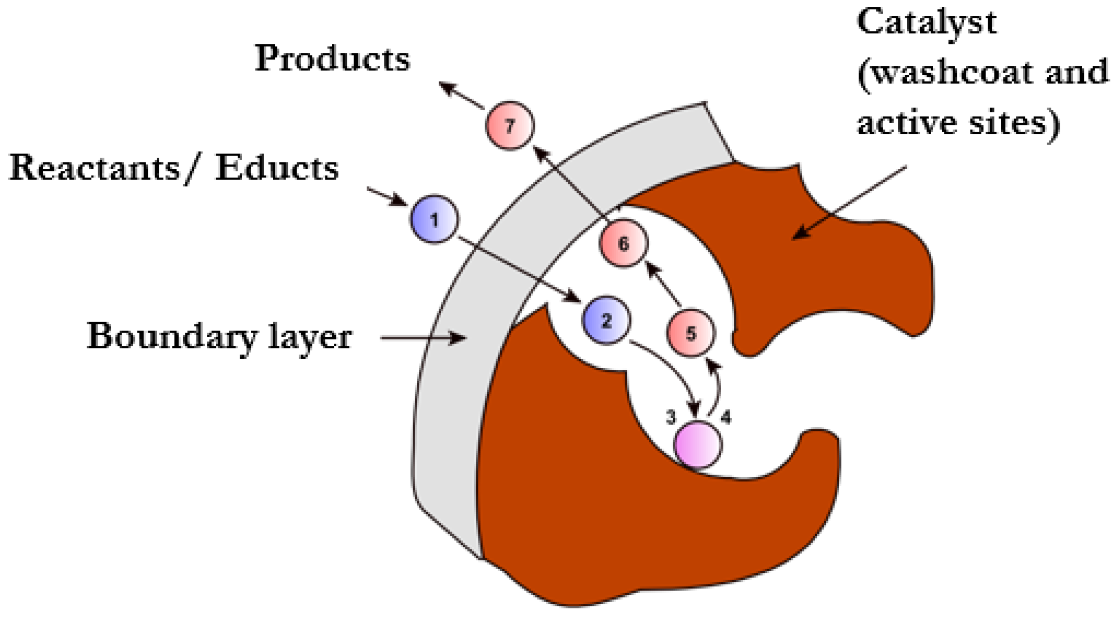
In general, heterogeneous catalytic conversion within honeycomb catalysts can be categorized by seven characteristic phases (Figure 17):
- Diffusion of reactants/educts (e.g., CO, O2) through the boundary layer (boundary layer diffusion);
- Diffusion of reactants into the pores of the washcoat (pore diffusion);
- Chemisorption of reactants/educts at the active sites;
- Chemical reaction of reactants/educts at the active sites;
- Desorption of products from the active sites;
- Diffusion of products out of the pores of the washcoat (pore diffusion);
- Diffusion of products (e.g., CO2) through the boundary layer into the flue gas flow through the honeycomb cells (boundary layer diffusion).
Figure 17.
Characteristic phases of heterogeneous catalysis [66] (translated into English). Copyright 2010, Use under the terms of the GNU Free Documentation License, Version 1.2, Roland Mattern, CC BY 3.0 https://creativecommons.org/licenses/by/3.0 (accessed on 25 November 2022) via Wikimedia Commons.
The overall reaction kinetics are influenced by catalytic selectivity, the concentrations of the reactants/educts and temperature conditions. The limiting effects of catalytic conversion are either transport mechanisms if the temperature is sufficiently high or reaction mechanisms if temperatures are low.
For the application of catalysts in stoves, there are two possibilities: either the catalyst is integrated (integrated system) or retrofitted (retrofitted systems). Relevant design parameters are:
- Temperatures (minimum, maximum, average);
- Pressure drops;
- Bypass according to requirements of respective EN standards, e.g., 3% of sectional area or at least 20 cm² of the flown-through sectional area [67];
- Accessibility for cleaning, maintenance and exchange.
Empirical experiments using several chimney stoves (EN 13240) with integrated Pt, Pd honeycomb catalysts showed emission conversion efficiencies of about 80% for CO and 30% for VOC and PM emissions, respectively (Equation (3)) [68,69].
Figure 18 illustrates the average emission concentrations of a heating operation cycle consisting of five successive batches at nominal load for integrated ceramic and metallic catalyst solutions. All catalysts were integrated in the post-combustion chamber upstream of the flue outlet, without any bypass. The operation of the stoves was carried out according to the user manuals.
A clear emission reduction potential was also observed for integrated catalytic foamed ceramics (active sites: Pt, Pd, Rh). According to experimental analysis, the emission conversion efficiencies were 45% for CO, 25% for VOC and 0% for PM emissions [25]. The conversion efficiencies were evaluated for heating cycles consisting of eight successive batches (batches 1–5 at nominal load with 100% batch mass and batches 6–8 at partial load with 50% batch mass). These tests were performed without any bypass in the flue gas pathway (i.e., bypass closed). The operation of the stove was based on a QUG, derived from the user’s manual.
The results of MACK et al. (2018) revealed no CH4 conversion efficiency. This concurs with other studies and is explainable by the average temperature levels in the range of 300–450 °C, which are far too low for catalytic CH4 oxidation (≥650 °C) [25,69].
Similar results were observed in the measurements of WÖHLER et al. (2017), which evaluated an integrated metallic honeycomb catalyst and an integrated catalytic foamed ceramic [64] (Table 4).
During these measurements, the stove was also operated using several batches at nominal (100% batch mass) and partial load (50% batch mass). In contrast to the findings of MACK et al. (2018) [25], PM emission conversion efficiency of about 30% was observed.
According to the literature [65], as well as experiences based on experimental tests [25,70], long-term operations result in agglomerations on the catalyst surface area, which affect the emission conversion efficiency. Hence, both integrated and retrofitted catalysts must be cleaned and maintained regularly [25,70]. Some manufactures recommend only a mechanical cleaning of the catalysts [40], but another possibility is additional cleaning with water, which removes water-soluble agglomerations on the catalyst surface [70].
Regarding the cost of catalysts available for stoves, there is limited or even no information publicly available. As a rough estimate, the costs of honeycomb catalysts used within the car sector, which range from €400 to €800, could be used as an indicator [71].
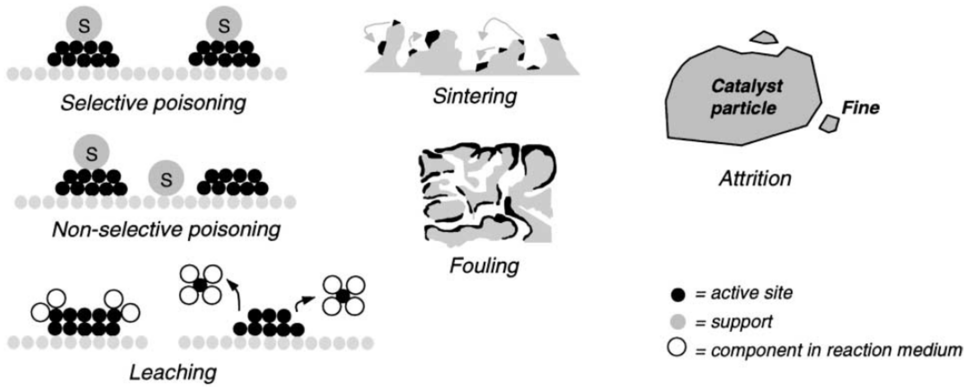
Finally, it must be mentioned that different deactivation mechanisms can result in premature losses of conversion efficiencies [38]. In general, potential deactivation mechanisms of heterogeneous catalysis are classified in three categories (Figure 19) [72,73]:
- Chemical deactivation is caused by selective or non-selective poisoning, which results in an inactivation of active sites by gaseous components, e.g., Pb, Zn, P or SO2. Furthermore, leaching is a type of chemical deactivation caused by undesired chemical reactions between gaseous compounds in the flue gas and the active sites of the catalyst, leading to a loss of those sites. Chemical deactivation mechanisms are mostly irreversible. Therefore, the operating conditions and the type of catalyst used must be adjusted, and critical components avoided, e.g., Pb, P, Zn and SO2 for Pt- and Pd-based catalysts;
- Thermal deactivation is caused by the reduction of the surface area of active sites or the porous surface of the washcoat due to sintering processes. Thermal deactivation is also irreversible and can be avoided by the appropriate design and operation of the appliance. In particular, maximum temperature conditions must be considered for the application of certain catalysts;
- Mechanical deactivation is caused by fouling processes, i.e., the deposition of particles on the pores and/or the active sites, or due to attrition, i.e., loss of active sites due to abrasion or mechanically induced crushing. Both mechanisms lead to a decrease of the catalytic conversion efficiency. However, deactivation by fouling is often (at least partially) reversible, e.g., by cleaning the catalyst or by oxidative regeneration of carbonaceous deposits.
Figure 19.
Illustration of the most relevant types of deactivation through heterogeneous catalysis [72]. Reprint with permission from J.A Moulijn, A.E van Diepen, F Kapteijn, Catalyst deactivation: is it predictable?: What to do?, Applied Catalysis A: General, Volume 212, Issues 1–2, 2001, Pages 3–16; Copyright 2001, Elsevier.
3.4.3. Foamed Ceramic (not Catalytically Coated)
Non-catalytic foamed ceramics (see also Figure 15) integrated between the main and post-combustion chamber are also sometimes mentioned as potential secondary measures for PM emission reduction. The reductive effect is based on a filtration effect on the surface of the foamed ceramic. This means that particles agglomerate on the surface area of the foamed ceramic structure and are subsequently oxidized at sufficiently high temperature levels. This approach is quite similar to the functionality of the packing technology. However, according to two different studies there were no significant PM emission conversion efficiencies observed based on experimental lab tests [25,64].
The costs of foamed ceramics depend on the dimensions. For example, a non-catalytic foamed ceramic with dimensions of 350mm x 350mm x 30mm costs about €75 [74].
3.4.4. Fabric Baghouse Filters
In general, the highest PM emission conversion efficiencies of > 99.0% up to 99.9% are achievable using fabric baghouse filters, even for fine particles (< 1µm) (Figure 20) [37]. The particle reduction is based on a filtration effect via the fabric baghouse material. Typically, fabric baghouse filters are automatically cleaned with pressurized air in when a certain pressure drop is exceeded.
Fabric baghouse filters are the state-of-the art for large industrial applications. However, due to the comparatively high pressure drops and the regular cleaning required, ventilators and pressurized air are necessary for regular operation. Furthermore, temperature levels and the filter fabric must be selected and checked properly in order to avoid fire risks. Therefore, fabric baghouse filters are typically not used for stoves operated under natural draught conditions (~10–50Pa), although they theoretically offer the highest PM emission reduction potential.
However, the R&D project “XyloClean” aims to develop and implement a combination of catalysts and fabric baghouse filters in stoves [75]. In detail, particulate filters based on sinter metals, which are extensively used in diesel cars, are catalytically coated and combined with a special flue gas routing (bypass), as well as a flue gas ventilator. Experimental measurements including the whole heating operation phase from cold start until stop revealed emission conversion efficiencies (Equation (3)) of about 90% for CO, about 60% for VOC and about 95% for PM emissions (based on mass concentrations). After regrading particle number distribution, the conversion efficiency was 98% [76,77].
Regarding the potential costs of such a system, no information is available. However, costs for particulate filters for cars start at €150 [78], but range on average between €1000 and €2000 [79]. Besides the costs for the particulate filter, there are additional costs for the catalytic coating, the ventilator and the specific flue gas routing.
3.4.5. Electrostatic Precipitator (ESP)
The principle of electrostatic precipitators is the ionization of particles using a discharge electrode and the subsequent separation of ionized particles on a collecting electrode (Figure 21). The electrical field is generated by a high voltage power supply in the range of 15 kV to 100 kV.
The separation or conversion efficiency () (see also Equation (3)) of an ESP can be estimated according to the following equation (Equation (5)) [37,80].
Besides the wet flue gas volume flow () and the effective surface of the collecting electrode (), the migration velocity (), i.e., the velocity of particles within the electric field, is essential. The migration velocity depends on the electrical conductivity of particles, flue gas temperature and flue gas composition, particle size and the effective electric field intensity [37]. The ESP design typically aims at flue gas velocities between the electrodes of 1.0 to 1.8 m/s [80].
For particles smaller than 100µm, high separation efficiencies are achievable (Figure 20). However, there is a minimum separation efficiency for particle sizes between 0.2 µm and 0.5 µm due to the transition of the dominating separation mechanism from impact ionization (dominant for particle sizes > 1 µm) to diffusion of ions induced by Brownian motion (dominant for particle sizes < 0.1 µm) [37].
Electrostatic precipitators are state-of-the-art for large industrial applications. The application of ESPs for small-scale applications, especially for stoves, is increasing since emission limit values have become more stringent in recent years, e.g., in Germany. In comparison to fabric baghouse filters, an important advantage is the low pressure drops of ESPs allow unproblematic operations under natural draught conditions. However, temperature conditions are also important and should generally range between 120°C and 180° in order to avoid flue gas condensation. Furthermore, combustion quality is essential since the separation efficiency of ESPs differs between mineral particles, tar and soot. Soot and tar especially can cause problems, either by sticking on the electrodes (tar) or by re-entrainment of particles into the flue gas flow (soot) [81].
Regarding the application of ESPs for manually operated room-heating appliances, there are several issues that are part of ongoing R&D projects or which might negatively affect acceptance by users [82,83]:
- Avoidance of noise, e.g., due to sparking;
- Avoidance of contamination, e.g., agglomerations in the chimney or release of flakes with particle sizes of about 5 mm;
- Integration or location of ESPs either in the chimney system (ESP is a separate system) or integrated in the room-heating appliance (ESP is part of the stove);
- High voltage in a living space (only relevant for integrated systems);
- Positioning of the electrodes in integrated systems for good accessibility (maintenance/cleaning) and to enable suitable temperature levels during operation;
- Combination of ESPs for PM emission reduction with secondary technologies focusing on gaseous emission reduction, e.g., catalysts.
Based on field monitoring during two heating periods, the PM emission conversion efficiencies of ESPs used as secondary emission abatement technologies for firewood stoves ranged from 60% to 80% (maximum 90%) [84]. The availabilities of the ESPs were also quite high (> 80%, max. 100%). The ESP operation started if a heating operation was detected and if the temperature difference between flue gas and surroundings exceeded a certain limit value [84]. The ESP was the OekoTube-Outside from the manufacturer Oekosolv AG.
Table 5 summarizes the results of field measurements carried out on two different slow-heat-release appliances (SHRA) [85].
The costs of the ESP OekoTube-Outside for end-users (without potential funding and installation costs) range between €1500 and €3000 [86]. This is in the same range of costs specified for similar ESPs from other manufacturers, e.g., the ESP “Airjekt 1” from the manufacturer Kutzner+Weber, which costs around €1700 to €1900 [87]
4. Discussion
4.1. SWOT Analysis
Table 6, Table 7 and Table 8 illustrate the results of SWOT analysis for primary and secondary measures.
In the case that the combustion principle is adapted, e.g., from a top-down to bottom-up/downdraft combustion principle, all other primary measures mentioned must be reconsidered and implemented.
4.2. Limits of Non-Technical Primary Measures
Informing users about correct heating, either generally or with appliance-specific information, represents the basis for the effectiveness of technical primary measures, as well as for long availability and maintenance intervals of potential secondary technologies. However, for some technical primary measures, e.g., the air staging concept, correct user behavior is an important precondition for its effectiveness. Consequently, incorrect user behavior can limit the effect of primary optimization measures or, in the worst case, even invert primary measures; e.g., secondary air might act as a primary air supply when there is an overloading of firewood in the combustion chamber.
However, due to a high time share of transient combustion conditions, as well as technical limits of manually operated firewood stoves, there are phases of batch combustion when emissions are increased even under best-practice operating patterns (Figure 6, Figure 7). Furthermore, in the daily use of firewood room-heating appliances, there will be situations when users deviate from best-practice heating operation even when they generally want to meet those requirements. Potential reasons can be either general high manual operating demands, which require effort, or conflicts with other activities in parallel with heating operation. Furthermore, it is evident that there are users who either have no interest in operating their appliances in best-practice mode or who think they know better; neither are motivated to change their heating habits [2].
To conclude, achieving a correct, area-wide heating operation mode or “best-practice” user behavior is essential to improving the pollution situation in the short term. Therefore, the optimization measures for user behavior improvement that have been identified should be implemented across the board despite their limitations. The most advantageous possibility seems to be the combination of all three measures, i.e., general information about “correct heating” via various information channels, appliance-specific QUGs and hands-on user training. One possibility for more widespread implementation of hands-on user training would be compulsory training before initial operation of the stove, e.g., carried out by installation personnel or chimney sweeps, or at one of the periodic inspections by the chimney sweep. This hands-on user training would be most efficient if the manufacturer has specified the appliance-specific best-practice user behavior via a QUG. If emission measurements are carried out by chimney sweeps, it would be also possible to quantitatively compare different user habits in terms of emissions and efficiency, and visualize the effects for users. This could be an option for the widespread implementation of the CleanAir mobile trailer approach for hands-on and even appliance-specific user training [33].
However, the optimization of user behavior alone, even if it is carried out impeccably, is not enough to achieve “(nearly) zero-emission stove technologies”. Technical primary measures and complementary secondary technologies are also required.
4.3. Limits of Technical-Primary Measures
Technical primary measures such as air staging or combustion chamber design are well-known and represent the state-of-the-art for combustion optimization. Hence, they should be implemented in all stove concepts. The demand for automatic combustion air regulation systems, especially those integrated into stoves, seems to be increasing too. Besides positive effects on emissions and thermal efficiency during real-life operation, the main reason for the increasing demand might be also the enhanced comfort for end-users, as they require less operating effort regarding adjustments of correct combustion air supply settings in relation to the specific combustion phases. Hence, automatic combustion air regulation systems, which combine non-technical and technical primary measures, can support appliance-specific best-practice heating operation.
However, there are also trends that contradict the approach of optimizing primary combustion conditions. For example, there has been an increase in window surface area for many stove models, especially for chimneys stoves (EN 13240) and closed inset appliances (EN 13229). The increase of window area might increase the emotional experience of flames for end-users, but is incompatible with minimal thermal heat losses from the combustion chamber and, consequently, with minimal emission release.
Another limiting factor for all the technical primary measures mentioned is the high time share of transient conditions for batch-wise firewood combustion. For example, the effectiveness during start-up and burn-out phases is limited since, during those phases, emissions are significantly increased, even in primary-optimized appliances (Figure 6, Figure 7).
In conclusion, primary measures are effective at reducing emissions and increasing efficiencies, but less so during transient combustion phases; they are also extremely negatively influenced by incorrect user behavior. Furthermore, more stringent emission limits and the trend towards real-life-oriented test methods for appliance performances (even periodically in real-life operation) might increase the use of secondary measures in the future.
Consequently, further emission reductions and developments towards “(nearly) zero-emissions technologies” require the complementary application of non-technical and technical primary and secondary measures [83,90]. Emphasis should be placed on the “complementary application”, since making use of the whole primary optimization potential is an important precondition for good availability of many secondary technologies. Additionally, cleaning and maintenance costs are lower and, in consequence, end-user costs are comparatively lower.
4.4. Synergies of Primary and Secondary Measures
Here, the potentials of the complementary application of primary and secondary optimization are analyzed and conceivable options for combinable measures/technologies are evaluated. It is important to mention the importance of correct and appliance-specific user behavior as an essential basis for the effectiveness of technical solutions. In an ideal case, secondary measures should be particularly effective during operating phases with limited effectiveness of technical and non-technical primary measures, e.g., cold start, start-up and burn-out phases. Of course, secondary measures usually also reduce emissions during the main combustion phases. The previously described secondary measures can be categorized into two types of technologies:
- Secondary technologies reducing only PM emissions;
- Secondary technologies reducing gaseous and particulate emissions (CO, VOC, PM).
The primary measures mentioned can be combined with technologies from those two categories (Table 9)
As shown in Table 9, the highest emission reduction potential for both gaseous and particulate emissions is the combination of primary measures with catalyst or packing technology together with an ESP or fabric baghouse filter. Fabric baghouse filters offer the highest theoretical PM emission reduction potential (Figure 20), but they have no effect on gaseous emissions (CO/VOC) and, as already mentioned, the pressure drops of fabric baghouse filters are significantly higher compared to ESPs. Hence, exclusive operation under natural draught conditions without the support of a ventilator is not possible. Consequently, costs might be higher for the application of fabric baghouse filters in comparison to ESPs. Furthermore, operation without electrical power is only possible with special flue gas routing (bypass).
Comparing oxidizing catalysts and packing technology, the most relevant differences are durability, maintenance efforts and investment costs. Furthermore, the requirement of a flue gas bypass for catalysts [67] in contrast to packing technology [60] represents an important difference. This is even more important considering that the emission conversion efficiencies presented in this paper refer only to the operating conditions of catalysts without any bypass [25,64,68,69].
Finally, the evaluation revealed that extensive technical primary optimization (e.g., based on the advanced combustion principle, air staging, combustion chamber design and automatic combustion air regulation) on the basis of correct and appliance-specific best-practice user behavior in combination with a catalyst or packing technology as well as an ESP would represent a suitable system to achieve significant emission reduction during real-life operation. Experimental assessment is still lacking to evaluate whether the application of packing technology or an integrated catalyst (with the required bypass) would be more beneficial. Regarding the application of ESPs in combination with firewood room-heating appliances, it is still an open question as to whether the integration of ESPs in the stove or in the chimney system would be more beneficial. Besides technological and economic aspects, a clear focus on user acceptance is also important (e.g., formation of flakes, noise, electric smog and high voltage in the living space).
5. Conclusions
All non-technical and technical primary and secondary measures evaluated were analyzed regarding functionality, important framework conditions for installation or application under natural draft conditions, emission reduction potential, costs (or prices for the end customer) and user comfort.
The analysis revealed that measures are needed to enhance appliance-specific best-practice user behavior, i.e., by a combination of general and appliance-specific information about “best-practice” heating and specific hands-on user training. Furthermore, the study showed that the implementation and application of technical primary measures is strongly recommended and, together with best-practice heating operation, is an important precondition for the effective and low-maintenance application of secondary emission abatement technologies. New products and stove installations benefit from the implementation of common technical primary measures, i.e., air supply and air staging, appropriate combustion chamber design and external draught control devices. However, the development and implementation of advanced combustion concepts from automatic firewood combustion, i.e., a change from top-down to bottom-up (or downdraft) combustion concepts, can significantly improve primary combustion conditions. The downdraft combustion concept seems to be especially suitable for slow-heat-release appliances or tiled stoves. Furthermore, the installation and application of integrated automatic combustion air regulation devices based on both flue gas temperature and flue gas CO2/O2 can significantly lower emissions and increase thermal efficiency. Additionally, such devices increase user comfort and minimize the risk of incorrect air settings during operation, which is a cause of incomplete combustion processes with high amounts of emissions. Furthermore, it is possible to use an automatic air regulation system to provide user feedback, e.g., via a display or LEDs, in order to support correct user behavior by supplying feedback to optimally recharge a new batch.
However, technical primary measures are limited due to a high time share of transient conditions during batch-wise combustion processes and various impacts of user behavior. Consequently, the complementary application of technical primary and secondary measures is necessary in order to achieve (nearly) zero-emission technologies. A promising technology that is close to being commercially available is the combination of packing technologies or catalysts with ESPs. Therefore, more R&D is necessary in order to compare and analyze both combinations. Long-term field evaluation under real-life end-user operation and natural draught conditions using different firewood room-heating technologies is essential.
Moreover, the analysis revealed some outstanding open questions, e.g., the user acceptance of flakes around the chimney when using ESPs and the pros and cons of appliance-integrated ESPs versus ESPs integrated in the chimney on the rooftop. Further R&D is also necessary regarding those aspects. Furthermore, R&D regarding maintenance efforts and economies between potential secondary emission abatement technologies is needed (e.g., catalysts versus packing technology). In the best case, secondary measures are particularly effective during transient combustion conditions, require low maintenance efforts, are cost-efficient and additionally enhance user comfort.
Lastly, primary and secondary measures are available for developing and installing manually operated firewood stoves that perform highly efficiently with low emissions in real-life operation. Due to increasingly stringent legal requirements regarding emissions and thermal efficiency, there is a trend towards (nearly) zero-emission technologies. Therefore, advanced combustion concepts, the implementation of technical primary measures and the complementary application of secondary emission abatement technologies together with a strong focus on appliance-specific best-practice heating operation (optimal user behavior) will be essential in the future. From a legal perspective, advanced test methods implemented as normative standards, including aspects of typical user behavior and the whole heating cycle from ignition to the cooling-down phase, might accelerate the development towards “(nearly) zero emission technologies” and, together with legal requirements, support quick and widespread market implementation.
Author Contributions
Conceptualization, G.R. and C.S.; methodology, G.R.; writing—original draft preparation, G.R.; writing—review and editing, C.S.; supervision, C.S.; project administration, G.R.; funding acquisition, C.S. All authors have read and agreed to the published version of the manuscript.
Funding
This research was funded by “WIRTSCHAFTSKAMMER NIEDERÖSTERREICH” (WKNÖ), grant number 12101722/1IPEDE.
Data Availability Statement
The data of the article are based on the provided references.
Acknowledgments
This study was carried out as part of the project E-Red (“Measures for Emissions REDuction of firewood stoves”), which was supported by the Austrian stove manufacturer ORTNER GmbH and was funded by the “Wirtschaftskammer Niederösterreich” (WKNÖ). The authors would also like to thank David Ben Whittaker for proofreading and support in English language editing.
Conflicts of Interest
The authors declare no conflict of interest. The funders had no role in the design of the study; in the collection, analyses, or interpretation of data; in the writing of the manuscript; or in the decision to publish the results.
References
- European Commission, DG TREN. Preparatory Studies for Eco-Design Requirements of EuPs (II)—LOT 15—Solid Fuel Small Combustion Appliances, Task 2: Economic and Market Analysis; European Commission: Strasbourg, France, 2009; pp. 1–47. Available online: https://www.eceee.org/static/media/uploads/site-2/ecodesign/products/solid-fuel-small-combustion-installations/bio-eup-lot-15-task2-final.pdf (accessed on 24 November 2022).
- Karlsson, B.S.; Håkansson, M.; Sjöblom, J.; Ström, H. Light my fire but don’t choke on the smoke: Wellbeing and pollution from fireplace use in Sweden. Energy Res. Soc. Sci. 2020, 69, 101696. [Google Scholar] [CrossRef]
- IEA. World Energy Outlook, Special Report, Energy and Air Pollution. 2016. Available online: https://www.iea.org/reports/energy-and-air-pollution (accessed on 19 May 2022).
- Hartmann, H. Strategies for Reducing the Impact on Air Quality from Residential and Commercial Wood Combustion. IEA Bioenergy-Task 32. In Proceedings of the IEA Bioenergy Triannual Conference: “Bioenergy—A Critical Part of the Path to Carbon Neutrality”, Online, 7 December 2021; Available online: https://www.ieabioenergyconference2021.org/wp-content/uploads/2021/12/11-05_HARTMANN.pdf (accessed on 24 November 2022).
- Sahlberg, A.; Karlsson, B.S.; Sjöblom, J.; Ström, H. Don’t extinguish my fire—Understanding public resistance to a Swedish policy aimed at reducing particle emissions by phasing out old wood stoves. Energy Policy 2022, 167, 113017. [Google Scholar] [CrossRef]
- European Commission. Commission Regulation (EU) 2015/1185 of 24, Implementing Directive 2009/125/EC of the European Parliament and of the Council with regard to ecodesign requirements for solid fuel local space heaters. Off. J. Eur. Union 2015, 193, 1–19. Available online: http://www.eceee.org/static/media/uploads/site-2/ecodesign/products/lot-20-local-room-heating-products/celex-32015r1185-en-txt.pdf (accessed on 24 November 2022).
- Mack, R.; Hartmann, H.; Schön, C. Influence of user behavior on emissions from firewood stoves. In Proceedings of the 27th European Biomass Conference and Exhibition, Lisbon, Portugal, 27–30 May 2019; Available online: https://www.tfz.bayern.de/mam/cms08/festbrennstoffe/dateien/cp_influence_of_user_behaviour_on_emissions_from_firewood_stoves_-_eu_bc_e_lisbon_2019.pdf (accessed on 24 November 2022).
- Mack, R.; Schön, C.; Kuptz, D.; Hartmann, H. Nutzereinflüsse auf das Emissionsverhalten von Kaminöfen—Anzünden, Lufteinstellungen, Brennstoff; Berichte aus dem TFZ, Nr. 61; Technologie- und Förderzentrum im Kompetenzzentrum für Nachwachsende Rohstoffe (TFZ): Straubing, Germany, 2019; p. 109. Available online: https://www.tfz.bayern.de/mam/cms08/festbrennstoffe/dateien/tfz_bericht_61_nutzereinfluesse.pdf (accessed on 24 November 2022).
- Reichert, G.; Schmidl, C. SWOT-Analysis of primary and secondary measures for firewood stoves. In Proceedings of the 30th European Biomass Conference and Exhibition, Virtual Conference, 9–12 May 2022. [Google Scholar]
- Reichert, G.; Hartmann, H.; Haslinger, W.; Oehler, H.; Mack, R.; Schmidl, C.; Schön, C.; Schwabl, M.; Stressler, H.; Sturmlechner, R.; et al. Effect of draught conditions and ignition technique on combustion performance of firewood room heaters. Renew. Energy 2017, 105, 547–560. [Google Scholar] [CrossRef]
- Reichert, G.; Schmidl, C.; Haslinger, W.; Schwabl, M.; Moser, W.; Aigenbauer, S.; Wöhler, M.; Hochenauer, C. Investigation of user behavior and assessment of typical operation mode for different types of firewood room heating appliances in Austria. Renew. Energy 2016, 93, 245–254. [Google Scholar] [CrossRef]
- Wöhler, M.; Andersen, J.S.; Becker, G.; Persson, H.; Reichert, G.; Schön, C.; Schmidl, C.; Jaeger, D.; Pelz, S.K. Investigation of real-life operation of biomass room heating appliances—Results of a European survey. Appl. Energy 2016, 169, 240–249. [Google Scholar] [CrossRef]
- Fachinger, F.; Drewnick, F.; Gieré, R.; Borrmann, S. How the user can influence particulate emissions from residential wood and pellet stoves: Emission factors for different fuels and burning conditions. Atmos. Environ. 2017, 158, 216–226. [Google Scholar] [CrossRef]
- Schieder, W.; Storch, A.; Fischer, D.; Thielen, P.; Zechmeister, A.; Poupa, S.; Wampl, S. Luftschadstoffausstoß von Festbrennstoff-Einzelöfen—Untersuchung des Einflusses von Festbrennstoff-Einzelöfen auf den Ausstoß von Luftschadstoffen; Umweltbundesamt GmbH: Wien, Austria, 2013; p. 368. ISBN 978-3-99004-253-3. Available online: https://www.umweltbundesamt.at/fileadmin/site/publikationen/REP0448.pdf (accessed on 25 November 2022).
- Meyer, N.K. Particulate, black carbon and organic emissions from small-scale residential wood combustion appliances in Switzerland. Biomass Bioenergy 2012, 36, 31–42. [Google Scholar] [CrossRef]
- Schmidl, C.; Luisser, M.; Padouvas, E.; Lasselsberger, L.; Rzaca, M.; Ramirez-Santa Cruz, C.; Handler, M.; Peng, G.; Bauer, H.; Puxbaum, H. Particulate and gaseous emissions from manually and automatically fired small scale combustion systems. Atmos. Environ. 2011, 45, 7443–7454. [Google Scholar] [CrossRef]
- Ozgen, S.; Caserini, S.; Galante, S.; Giugliano, M.; Angelino, E.; Marongiu, A.; Hugony, F.; Migliavacca, G.; Morreale, C. Emission factors from small scale appliances burning wood and pellets. Atmos. Environ. 2014, 94, 144–153. [Google Scholar] [CrossRef]
- Schön, C.; Hartmann, H. Log wood combustion in stoves—Influence on emissions and efficiency. In Proceedings of the 20th European Biomass Conference and Exhibition, Milan, Italy, 18–22 June 2012; Available online: https://www.tfz.bayern.de/mam/cms08/festbrennstoffe/dateien/cp_log_wood_combustion_in_stoves_%E2%80%93_influence_on_emissions_and_efficiency_-_eu_bc_e_milan_2012.pdf (accessed on 25 November 2022).
- Schön, C.; Hartmann, H. Nutzer- und Brennstoffeinflüsse auf Feinstaubemissionen aus Kleinfeuerungen; Berichte aus dem TFZ, Nr. 36; Technologie- und Förderzentrum im Kompetenzzentrum für Nachwachsende Rohstoffe (TFZ): Straubing, Germany, 2014; p. 109. Available online: https://www.tfz.bayern.de/mam/cms08/festbrennstoffe/dateien/36_bericht.pdf (accessed on 25 November 2022).
- Nord-Larsen, T.; Bergstedt, A.; Farver, O.; Heding, N. Drying of firewood—The effect of harvesting time, tree species and shelter of stacked wood. Biomass Bioenergy 2011, 35, 2993–2998. [Google Scholar] [CrossRef]
- Hartmann, H.; Schön, C.; Turowski, P.; Obernberger, I.; Biedemann, F.; Bäfver, L.; Finnan, J. Low Emission Operation Manual for Chimney Stove Users; Report within the Scope of the ERA-NET Project “FutureBio Tec”; Bioenergy: Graz, Österreich, 2012; Available online: https://www.tfz.bayern.de/mam/cms08/festbrennstoffe/dateien/futurebiotec-low_emission_operation_manual_for_chimney_stove_users.pdf (accessed on 28 November 2022).
- Spitzer, P.; Enzinger, G.; Fankhauser, G.; Fritz, W.; Golja, F.; Stiglbrunner, R. Emissionsfaktoren für Feste Brennstoffe, Endbericht; Johanneum Research: Graz, Austria, 1998; p. 36. Available online: https://silo.tips/download/endbericht-emissionsfaktoren-fr-feste-brennstoffe-j-spitzer-p-enzinger-g-fankhau (accessed on 25 November 2022).
- Brandelet, B.; Rose, C.; Rogaume, C.; Rogaume, Y. Impact of ignition technique on total emissions of a firewood stove. Biomass Bioenergy 2018, 108, 15–24. [Google Scholar] [CrossRef]
- Nussbaumer, T.; Doberer, A.; Klippel, N.; Bühler, R.; Vock, W. Influence of ignition and operation type on particle emissions from residential wood combustion. In Proceedings of the 16th European Biomass Conference and Exhibition, Valencia, Spain, 2–6 June 2008; Available online: http://www.verenum.ch/Publikationen/Biomass-Conf9.5.pdf (accessed on 25 November 2022).
- Mack, R.; Kuptz, D.; Schön, C.; Hartmann, H. Optimierungspotenziale bei Kaminöfen; Berichte aus dem TFZ, Nr. 57; Technologie- und Förderzentrum im Kompetenzzentrum für Nachwachsende Rohstoffe (TFZ): Straubing, Germany, 2018; p. 116. Available online: https://www.tfz.bayern.de/publikationen/berichte/234589/index.php (accessed on 25 November 2022).
- Sturmlechner, R.; Stressler, H.; Schwabl, M.; Reichert, G.; Carlon, E.; Haslinger, W.; Schmidl, C.; Weissinger, A. Emission factor assessment for two firewood stoves. WIT Trans. Ecol. Environ. 2017, 211, 171–182. [Google Scholar] [CrossRef] [Green Version]
- BMK-Bundesministerium Klimaschutz, Umwelt, Energie, Mobilität, Innovation und Technologie, Richtig Heizen mit Holz. Available online: https://www.bmk.gv.at/dam/jcr:16f8e912-bde5-4929-b6af-03f0f2e6cd56/Folder_richtig_heizen_mit_Holz.pdf (accessed on 25 November 2022).
- Hartmann, H.; Schön, C.; Turowski, P. Richtig heizen. Der Betrieb von Kaminöfen; TFZ-Wissen, Nr.1; Technologie- und Förderzentrum im Kompetenzzentrum für Nachwachsende Rohstoffe (TFZ): Straubing, Germany, 2015; p. 31. Available online: http://www.tfz.bayern.de/mam/cms08/festbrennstoffe/dateien/tfz_wissen_b_web_s.pdf (accessed on 25 November 2022).
- HKI-Industrieverband Haus-, Heiz- und Küchentechnik e.V., Heizen mit Holz—So geht’s Richtig. Available online: https://www.youtube.com/watch?v=l9HeeoAIEnk (accessed on 25 November 2022).
- Umweltbundesamt GmbH. BMK-Bundesministerium Klimaschutz, Umwelt, Energie, Mobilität, Innovation und Technologie (Ed.), Richtig heizen. Available online: https://www.richtigheizen.at/ (accessed on 25 November 2022).
- CleanAir—R&D Project. Available online: https://www.best-research.eu/de/kompetenzbereiche/verbrennung/projekte/view/615 (accessed on 25 November 2022).
- Kirchsteiger, B.; Kubik, F.; Sturmlechner, R.; Stressler, H.; Schwabl, M.; Kistler, M.; Kasper-Giebl, A. Real-life emissions from residential wood combustion in Austria: From TSP emissions to PAH emission profiles, diagnostic ratios and toxic risk assessment. Atmos. Pollut. Res. 2021, 12, 101127. [Google Scholar] [CrossRef]
- Schwabl, M. Raising awareness and changing behaviour with the traveling combustion education—The CleanAir II project. In Proceedings of the IEA Bioenergy Triannual Conference: “Bioenergy—A Critical Part of the Path to Carbon Neutrality”, Online, 7 December 2021; Available online: https://www.ieabioenergyconference2021.org/wp-content/uploads/2021/12/11-04_SCHWABL.pdf (accessed on 25 November 2022).
- beReal—R&D Project. Advanced Testing Methods for Better Real Life Performance of Biomass Heating Appliances. Available online: http://www.bereal-project.eu/ (accessed on 25 November 2022).
- Reichert, G.; Sturmlechner, R.; Stressler, H.; Schwabl, M.; Schmidl, C.; Oehler, H.; MACK, R.; Hartmann, H. Deliverable D3.3-Final Report: Definition of Suitable Measurement Methods and Advanced Type Testing Procedure for Real Life Conditions, 30. September 2016, 35p. Available online: http://www.bereal-project.eu/uploads/1/3/4/9/13495461/d3.3_definition_of_suitable_measurement_methods_final_1.pdf (accessed on 25 November 2022).
- Rönnback, M.; Persson, H.; Jespersen, M.G.; Jensen, J.H. Deliverable D7.1—Documentation and Evaluation of Field Data Demonstration 30 September 2016, 36 p. Available online: http://www.bereal-project.eu/uploads/1/3/4/9/13495461/d7.1_documentation_and_evaluation_of_field_data_demonstration_final_1.pdf (accessed on 25 November 2022).
- Gaderer, M.; Gölles, M.; Hartmann, H.; Hofbauer, H.; Kaltschmitt, M.; Keil, F.; Nussbaumer, T.; Spliethoff, H. Direkte thermo-chemische Umwandlung (Verbrennung). In Energie aus Biomasse. Grundlagen, Techniken und Verfahren, 3rd ed.; Kaltschmitt, M., Hartmann, H., Hofbauer, H., Eds.; Springer: Berlin/Heidelberg, Germany, 2016. [Google Scholar] [CrossRef]
- Warming-Jespersen, M.G. Technical Guidelines for Design of low Emission Stoves; IEA Task 32, IEA Webinar 06.05.2021. Available online: https://task32.ieabioenergy.com/wp-content/uploads/sites/2/2020/06/02_Technical-guidelines-for-design-of-low-emission-stoves-22-01-2020.pdf (accessed on 25 November 2022).
- Schwingruber, P.; Horat, P.; Nussbaumer, T. Optimierung der Mischung von Sekundärluft und Gasen Thomas Nussbaumer (Hrsg.). In 13. Holzenergie-Symposium: Entwicklungen für Wärme, Kraft und Fernwärme aus Holz. Tagung an der ETH Zürich am 12. September 2014; Verenum: Zürich, Switzerland, 2014; ISBN 3-908705-25-8. [Google Scholar]
- Brunner, T.; Obernberger, I.; Scharler, R. Primary measures for low-emission residential wood combustion – comparison of old with optimized modern systems. In Proceedings of the 17th European Biomass Conference & Exhibition, ETA-renewable Energies, Hamburg, Germany, 29 June–3 July 2009; Available online: https://www.bios-bioenergy.at/images/bios/downloads/publikationen/Pellets/091-Paper-Brunner-Primary-measures-for-low-emission-wood-combustion-EUBCE2009.pdf (accessed on 25 November 2022).
- Scharler, R.; Gruber, T.; Ehrenhöfer, A.; Kelz, J.; Bardar, R.M.; Bauer, T.; Hochenauer, C.; Anca-Couce, A. Transient CFD simulation of wood log combustion in stoves. Renew. Energy 2020, 145, 651–662. [Google Scholar] [CrossRef]
- Virén, A.; Lamberg, H.; Tissari, J.; Sippula, O.; Jokiniemi, J.; Hartmann, H.; Schön, C. Guidelines for Low Emission Chimney Stoves Design; Report within the Scope of the ERA-NET Project “FutureBio Tec”; Bioenergy: Graz, Österreich, 2012; Available online: https://www.researchgate.net/publication/326316692_Guideline_for_Low_Emission_Chimney_Stove_Design (accessed on 25 November 2022).
- Österreichischer Kachelofenverband. Technischer Ausschuss, UmweltPlus Brennraum; Merkblatt 10; Ausgabe: Wien, Österreich, 2018; Available online: https://docplayer.org/168903887-Umweltplus-brennraum.html (accessed on 25 November 2022).
- ÖNORM EN 16510-1:2018 12 01; Residential Solid Fuel Burning Appliances—Part 1: General Requirements and Test Methods. Austrian Standards: Vienna, Austria, 2018.
- ZUK 130 DW—Zugbegrenzer. Available online: https://www.raab-gruppe.de/portfolio-items/zugbegrenzer-zuk-130-dw/#tab-b63621274509f7f9978 (accessed on 25 November 2022).
- ORTNER GmbH. Das Ortner Berechnungsprogramm, Anleitung. Juni 2020. Available online: https://berechnungsprogramm.ortner-cc.at/ (accessed on 25 November 2022).
- Reichert, G. Primary- and secondary measures for manually fired stoves—An overview. In Proceedings of the 6th Central European Biomass Conference, Graz, Austria, 24 December 2019–22 January 2020; Available online: https://www.best-research.eu/files/publications/pdf/CleanAirII_Primary_Secondary_Measures_200121_GabrielReichert.pdf (accessed on 25 November 2022).
- Illerup, J.; Mandl, C.; Obernberger, I.; Mack, R.; Hartmann, H.; Schüssler, I.; Furborg, J.; Volz, F. Guidelines for Automated Control Systems for Stoves; Report within the Scope of the ERA-NET Project “Woodstove2020”. Development of Next Generation and Clean Wood Stoves, July 2017 Bios Bioenergiesysteme. Available online: https://backend.orbit.dtu.dk/ws/files/140796742/Guidelines_Control_final.pdf (accessed on 25 November 2022).
- Energie-Experten. Overview about Automatic Combustion Air Regulation Systems (Selection). Available online: https://www.energie-experten.org/heizung/ofen/ofentechnik/abbrandsteuerung (accessed on 19 May 2022).
- Hwam, Wiking® Automatic™. Available online: https://hwam.com/advantages/wiking-automatic (accessed on 25 November 2022).
- Hwam, Hwam® Smartcontroltm. Available online: https://hwam.com/advantages/hwam-smart-control (accessed on 25 November 2022).
- Illerup, J.B.; Hansen, B.B.; Lin, W.; Nickelsen, J.; Dam Johansen, K. Intelligent heat system—High-Energy efficient wood stoves with low emissions. In Proceedings of the Seminar on Real-World Emissions from Residential Wood Combustion, Copenhagen, Denmark, 3 December 2015; p. 24. Available online: https://envs2.au.dk/Projekter/Seminar_RealWorldEmissions/Illerup_RealWorldEmissions.pdf (accessed on 19 May 2022).
- Illerup, J.B.; Hansen, B.B.; Lin, W.; Nickelsen, J.; Pedersen, V.H.; Eskerod, B.; Dam-Johansen, K. Performance of an automatically controlled wood stove: Thermal efficiency and carbon monoxide emissions. Renew. Energy 2020, 151, 640–647. [Google Scholar] [CrossRef]
- Nussbaumer, T. Combustion and Co-combustion of Biomass: Fundamentals, Technologies, and primary Measures for Emission Reduction. Energy Fuels 2003, 17, 1510–1521. Available online: http://www.verenum.ch/Publikationen/comb%20_cocomb.pdf (accessed on 25 November 2022). [CrossRef]
- Wiest, W. Sturzbrandfeuerung für Kaminöfen—Technik und Anwendungen Thomas Nussbaumer (Hrsg.). In 13. Holzenergie-Symposium: Entwicklungen für Wärme, Kraft und Fernwärme aus Holz. Tagung an der ETH Zürich am 12. September 2014; Verenum: Zürich, Switzerland, 2014; ISBN 3-908705-25-8. [Google Scholar]
- Kaminofen xeoos 8 kW, Technical Specifications. Available online: https://www.xeoos.de/fileadmin/daten/downloads/technik/neu/Leistungserklaerung_x8_140409.pdf (accessed on 25 November 2022).
- Kaminofen xeoos 5 kW, Technical Specifications. Available online: https://www.xeoos.de/fileadmin/daten/downloads/technik/neu/Leistungserklaerung_x5_140409.pdf (accessed on 25 November 2022).
- Attika, Bionic Fire 4,6 kW, Technical Specifications. Available online: https://pass.attika-intern.ch/ccp/files/121/BIONIC_FIRE_EVO_Datenblatt.pdf (accessed on 25 November 2022).
- Nussbaumer, T. Staubabscheidesysteme—Eine Einführung, BAFU-Fachtagung Holzverbrennung und Feinstaub, Bern 08.11.2011. Available online: https://www.bafu.admin.ch/dam/bafu/de/dokumente/luft/fachinfo-daten/staubabscheidesysteme-eineeinfuehrung.pdf.download.pdf/staubabscheidesysteme-eineeinfuehrung.pdf (accessed on 25 November 2022).
- Aleysa, M.; Leistner, P. Verbesserung des Verbrennungs- und Emissionsverhaltens in Biomassebetriebenen Einzelraumfeuerungsanlagen durch den Einsatz Spezieller Einbauten; Abschlussbericht über ein Forschungsprojekt gefördert von der Fachagentur für Nachwachsende Rohstoffe (FKZ: 13NR104); Fraunhofer—Institut für Bauphysik IBP: Stuttgart, Germany, 2016; Available online: http://docplayer.org/113343304-Verbesserung-des-verbrennungs-und-emissionsverhaltens-in-biomassebetriebenen-einzelraumfeuerungsanlagen-durch-den-einsatz-spezieller-einbauten.html (accessed on 25 November 2022).
- Aleysa, M. Packing technology for emission reduction in wood-burning stoves and biomass boilers. In Thomas Nussbaumer (Hrsg.), 15. Holzenergie-Symposium: Netzintegration, Vorschriften und Feuerungstechnik; Tagung an der ETH Zürich am 14. September 2018; Verenum: Zürich, Switzerland, 2018; ISBN 3-908705-36-3. Available online: http://www.holzenergie-symposium.ch/Dokumente/Tgband15HES.pdf (accessed on 25 November 2022).
- PALL-RINGE, Evaluation of Costs. Available online: https://de.made-in-china.com/tag_search_product/Pall-Rings_eiueron_1.html (accessed on 29 November 2022).
- File:CatalysisScheme.png. Copyright 2008, Attribution: No Machine-Readable Author Provided. Smokefoot Assumed (Based on Copyright Claims)., Public Domain, via Wikimedia Commons. Available online: https://commons.wikimedia.org/wiki/File:CatalysisScheme.png (accessed on 25 November 2022).
- Wöhler, M.; Jaeger, D.; Pelz, S.K.; Thorwarth, H. Potential of Integrated Emissions Reduction Systems in a Firewood Stove under Real Life Operation Conditions. Energy Fuels 2017, 31, 7562–7571. [Google Scholar] [CrossRef] [Green Version]
- VDI 3476-1. Guideline: Waste gas cleaning-methods of catalytic waste Gas cleaning. In Fundamentals, Kommission Reinhaltung der Luft im VDI und DIN—Normenausschuss KRdL; Beuth GmbH: Berlin, Germany, 2005; pp. 2–25. [Google Scholar]
- Mattern, R. Heterogene Katalyse, Prozessschritte, 15 August. 2010. Available online: https://commons.wikimedia.org/wiki/File:Heterogene_Katalyse_2.svg (accessed on 25 November 2022).
- BLUEFIRE GmbH. Instruction Manual Catalyst. Available online: https://blue-fire.org/wp-content/uploads/2021/07/Betriebsanleitung-Blue-Fire-Katalysator-en4.pdf (accessed on 25 November 2022).
- Reichert, G.; Schmidl, C.; Haslinger, W.; Stressler, H.; Sturmlechner, R.; Schwabl, M.; Wöhler, M.; Hochenauer, C. Impact of oxidizing honeycomb catalysts integrated in firewood stoves on emissions under real-life operating conditions. Fuel Process. Technol. 2018, 177, 109–118. [Google Scholar] [CrossRef]
- Reichert, G.; Schmidl, C.; Haslinger, W.; Stressler, H.; Sturmlechner, R.; Schwabl, M.; Wöhler, M.; Hochenauer, C. Catalytic efficiency of oxidizing honeycomb catalysts integrated in firewood stoves evaluated by a novel measuring methodology under real-life operating conditions. Renew. Energy 2018, 117, 300–313. [Google Scholar] [CrossRef]
- Reichert, G.; Schmidl, C.; Haslinger, W.; Stressler, H.; Sturmlechner, R.; Schwabl, M.; Wöhler, M.; Hochenauer, C. Long term durability and safety aspects of oxidizing honeycomb catalysts integrated in firewood stoves. Biomass Bioenergy 2017, 105, 428–442. [Google Scholar] [CrossRef]
- Estimation of Costs (In Relation to Products Used in the Car Sector). Available online: https://werkstatt-kosten.net/katalysator-kosten/ (accessed on 25 November 2022).
- Moulijn, J.A.; Van Diepen, A.E.; Kapteijn, F. Catalyst deactivation: Is it predictable? What to do? Appl. Catal. A Gen. 2001, 212, 3–16. [Google Scholar] [CrossRef]
- Bartholomew, C.H. Mechanisms of catalyst deactivation. Appl. Catal. Gen. 2001, 2012, 17–60. [Google Scholar] [CrossRef]
- Costs of Foamed Ceramics (Not Catalytical Coated). Available online: https://www.schamotte-shop.de/feinstaub-russfilter-350x350x30mm.html?gclid=EAIaIQobChMItd_6xZOk8wIV1eF3Ch30iwjhEAQYBSABEgJpn_D_BwE (accessed on 25 November 2022).
- Xyloclean, R&D project. Available online: https://heig-vd.ch/rad/instituts/igt/projets/xyloclean (accessed on 25 November 2022).
- Roppa, J.; Roethlisbergerb, R.P.; Rothc, S.; Bourgeoisd, J.P. XYLOCLEAN: Combustion Regulation and Treatment of Smoke from a wood stove. In Proceedings of the 28th International Conference on Efficiency, Cost, Optimization, Simulation and Environmental Impact of Energy Systems, Pau, France, 30 June–3 July 2015; Available online: https://heig-vd.ch/docs/default-source/doc-institut-igt/xylocleani_publication_ecos2015.pdf?sfvrsn=608972e5_0 (accessed on 25 November 2022).
- Baillifard, M.-A.; Ropp, J. Wood log combustion and flue gas after treatment HEIG-VD. DBFZ Deutsches Biomasseforschungszentrum gemeinnützige GmbH (Hrsg.); In 12. Fachgespräch—Partikelabscheider in häuslichen Feuerungen; DBFZ: Leipzig, Germany, 2021. [Google Scholar]
- Kfzteile 24, Costs of Particulate Filters (Cars). Available online: https://www.kfzteile24.at/kategorie/ersatzteile-verschleissteile/abgasanlage/russ-partikelfilter (accessed on 19 May 2022).
- Motointegrator. Rußpartikelfilter—Funktion, Reinigung und Reparaturkosten. 2020. Available online: https://www.motointegrator.de/blog/russpartikelfilter-funktion-reinigung-und-reparaturkosten/ (accessed on 25 November 2022).
- Strauss, K. Kraftwerkstechnik zur Nutzung Fossiler, 7th ed.; Nuklearer und Regenerativer Energiequellen; Springer Vieweg: Berlin, Germany, 2016. [Google Scholar] [CrossRef]
- Lauber, A. Charakterisierung der Partikelarten aus der Holzverbrennung und Eigenschaften in Elektroabscheidern, Thomas Nussbaumer (Hrsg.). In 11. Holzenergie-Symposium: Potenzial zur Holzenergie-Nutzung. Tagung an der ETH Zürich am 17. September 2010; Verenum: Zürich, Switzerland, 2010; ISBN 3-908705-21-5. [Google Scholar]
- Kiener, S.; Turowski, P.; Hartmann, H.; Schmoekel, G. Bewertung Kostengünstiger Staubabscheider für Einzelfeuerstätten und Zentralheizungskessel; Berichte aus dem TFZ, Nr. 23; Technologie- und Förderzentrum im Kompetenzzentrum für Nachwachsende Rohstoffe (TFZ): Straubing, Germany, 2010; p. 144. Available online: https://www.tfz.bayern.de/mam/cms08/festbrennstoffe/dateien/23_bericht.pdf (accessed on 25 November 2022).
- Wüest, J. Zehn Jahre grundlegende Erfahrungen mit Partikel, Messen und Abscheidern Deutsches Biomasseforschungszentrum gemeinnützige GmbH (Hrsg.). In 12. Fachgespräch—Partikelabscheider in Häuslichen Feuerungen; DBFZ: Leipzig, Germany, 2021. [Google Scholar]
- Zotter, P.; Lauber, A.; Nussbaumer, T. Monitoring des Praxisbetriebs von Elektroabscheidern bei sieben Kleinfeuerungen über zwei Heizperioden. In 12. Fachgespräch—Partikelabscheider in Häuslichen Feuerungen; AG, DBFZ Deutsches Biomasseforschungszentrum gemeinnützige GmbH (Hrsg.); Verenum: Zurich, Switzerland.
- Lauber, A.; Nussbaumer, T. Erfolgskontrolle zum Pilotprojekt Feinstaubabscheider im Misox; Schlussbericht: Verenum, Zürich, 2019; Available online: https://www.gr.ch/DE/institutionen/verwaltung/ekud/anu/ANU_Dokumente/ANU-409-95d_Schlussbericht_2019_Pilotprojekt_Misox.pdf (accessed on 25 November 2022).
- OekoSolve AG, Costs OekoTube-Outside. Available online: https://oekosolve.com/produkte/feinstaubfilter-fuer-wohnzimmerfeuerungen/feinstaubfilter-oekotube/ (accessed on 25 November 2022).
- KUTZNER+WEBER, Preis auf Ofenexperte.de für den E-Abscheider „Airjekt 1“. Available online: https://www.ofenexperte.de/zubehoer/feinstaub-partikelabscheider/13889/feinstaubpartikelabscheider-airjekt-1-basic-zur-montage-im-innenbereich (accessed on 25 November 2022).
- Reichert, G.; Schmidl, C. Advanced Test Methods for Firewood Stoves—Report on Consequences of Real-Life Operation on Stove Performance; IEA Bioenergy Task 32; IEA Bioenergy: Wieselburg, Austria, 2018; Available online: https://www.ieabioenergy.com/wp-content/uploads/2018/11/IEA_Bioenergy_Task32_Test-Methods.pdf (accessed on 25 November 2022).
- Hartmann, I.; Tebert, C. The new Blue Angel ecolabel certification method for firewood stoves. In Proceedings of the Central European Biomass Conference 2020 Workshop IEA Task 32, Graz, Austria, 23 January 2020; Available online: https://task32.ieabioenergy.com/wp-content/uploads/sites/24/2020/06/04_Blue-Angel-Stoves.pdf (accessed on 25 November 2022).
- Nussbaumer, T. Introduction to Biomass Combustion and Pollutant Reduction in Wood Stoves and Boilers; IEA Webinar 06.05.2021; IEA Bioenergy: Wieselburg, Austria, 2021; Available online: https://www.ieabioenergy.com/wp-content/uploads/2021/05/Nussbaumer-2021_05_06_IEA-Webinar.pdf (accessed on 25 November 2022).
- Baranowski, T. Unser Beitrag zum Umweltschutz! Zero Emission Now! In 12. Fachgespräch—Partikelabscheider in Häuslichen Feuerungen; DBFZ: Leipzig, Germany, 2021. [Google Scholar]
- Kramb, J.H. Der Schräder PTI (Particulate Trap Inside) für Kesselleistungen bis 50 kW und ein Ausblick auf die Kombination schwenkbarer Katalysatoren mit Partikelabscheider PTI als Ofenaufsatz, Schräder Abgastechnologie. In 12. Fachgespräch—Partikelabscheider in Häuslichen Feuerungen; DBFZ: Leipzig, Germany, 2021. [Google Scholar]
Figure 1.
Share of technologies in about 65 million room-heating appliances in Europe. Own figure, based on data of [1].
Figure 1.
Share of technologies in about 65 million room-heating appliances in Europe. Own figure, based on data of [1].

Figure 2.
Placement of kindling material and firewood pieces according to top-down (a) and bottom-up (b,c) ignition techniques. Cross joint placement (a,b) and traditional placement like a campfire (c) [10,11]. (a,b) Reprint with permission from G. Reichert, H. Hartmann, W. Haslinger, H. Oehler, R. Mack, C. Schmidl, C. Schön, M. Schwabl, H. Stressler, R. Sturmlechner, C. Hochenauer, Effect of draught conditions and ignition technique on combustion performance of firewood roomheaters, Renewable Energy, Volume 105,2017,Pages 547–560; Copyright 2017, Elsevier. (c) Reprint with permission from G. Reichert, C. Schmidl, W. Haslinger, M. Schwabl, W. Moser, S. Aigenbauer, M. Wöhler, C. Hochenauer, Investigation of user behavior and assessment of typical operation mode for different types of firewood room-heating appliances in Austria, Renewable Energy, Volume 93, 2016, Pages 245–254; Copyright 2016, Elsevier.
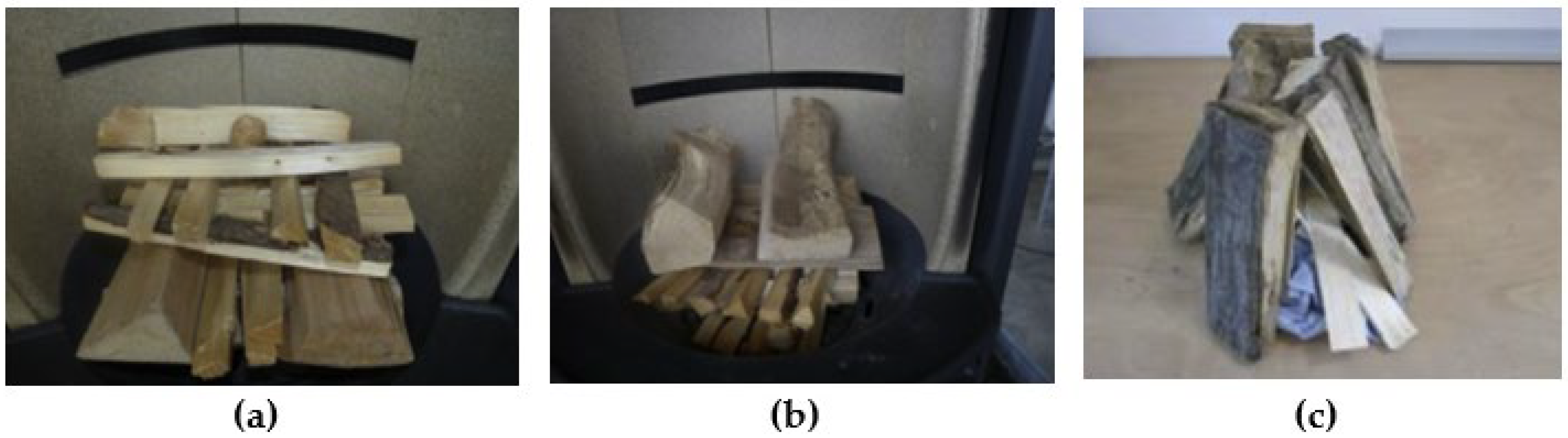
Figure 3.
Average benzo(a)pyrene emissions of three batches of four room-heating appliances (1, 2, 4: chimney stoves, 3: tiled stove) when operated according to users’ own habits and according to best-practice heating operation. Error bars represent the standard deviation of measurements. Own figure, based on data of [32].

Figure 4.
Illustration of air supply and air staging concept of a room-sealed chimney stove [28]. Reprint with permission from H. Hartmann, C. Schön, P. Turowski, Richtig heizen. Der Betrieb von Kaminöfen. TFZ-Wissen, Nr.1, Straubing, 2020, p. 31; Copyright 2020, Technologie- und Förderzentrum (TFZ).

Figure 5.
External draught control device ZUK 130 DW (left) and its functionality (right) from the company Kutzner + Weber (K+W) [45] (translated into English). Reprint with permission from Zugbegrenzer ZUK 130 DW; Copyright 2015, Kutzner + Weber GmbH.
Figure 5.
External draught control device ZUK 130 DW (left) and its functionality (right) from the company Kutzner + Weber (K+W) [45] (translated into English). Reprint with permission from Zugbegrenzer ZUK 130 DW; Copyright 2015, Kutzner + Weber GmbH.
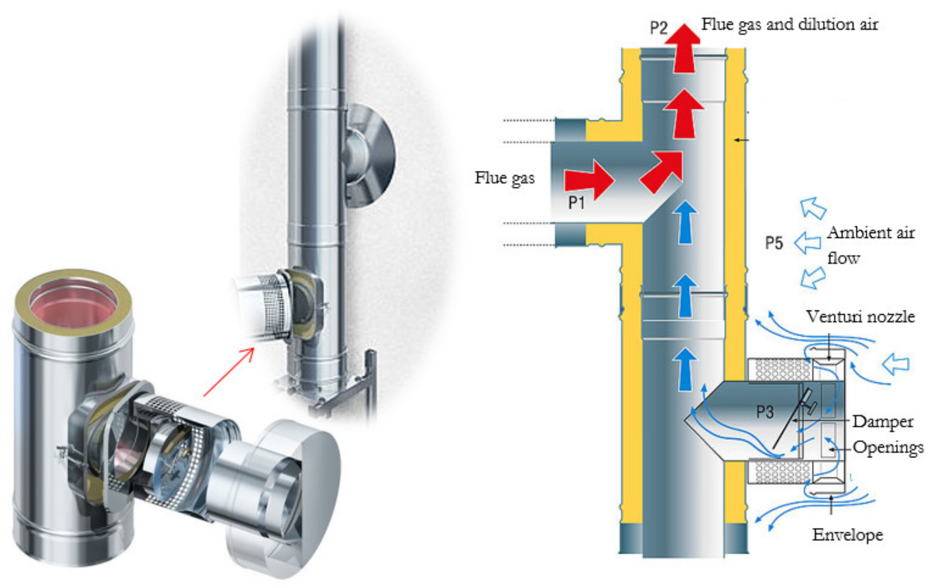
Figure 6.
Characteristic phases of batch-wise firewood combustion: (1) start-up phase, (2) main burning phase, (3) burn-out phase [47]. Reprint with permission from G. Reichert, Primary- and Secondary Measures for Manually Fired Stoves - An Overview. 6th Central European Biomass Conference, 2020, Austria, Graz; Copyright 2020, BEST GmbH.
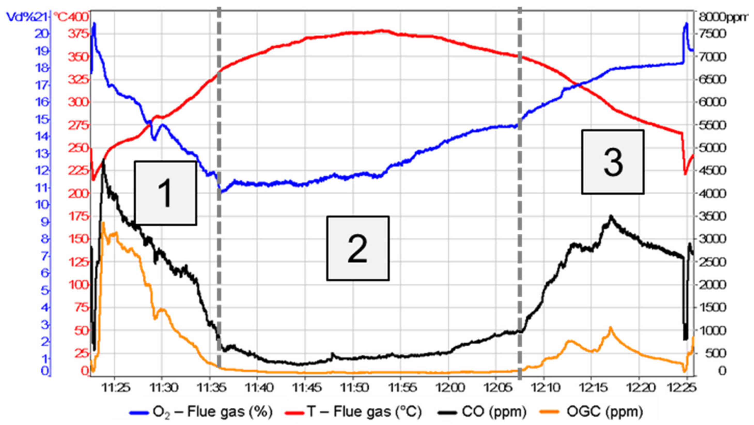
Figure 7.
Illustration of a fuel batch of a conventional uncontrolled stove (left) and an automatically controlled stove (right) [48]. Reprint with permission from J. Illerup, C. Mandl, I. Obernberger, R. Mack, H. Hartmann, I. Schüssler, J. Furborg, F. Volz, Guidelines for automated control systems for stoves, Report within the scope of the ERA-NET Project “Woodstove2020” – Development of Next Generation and Clean Wood Stoves, July 2017; Copyright 2017, BIOS BIOENERGIESYSTEME GmbH (https://www.bios-bioenergy.at/index.php/en (accesed on 25 November 2022)).
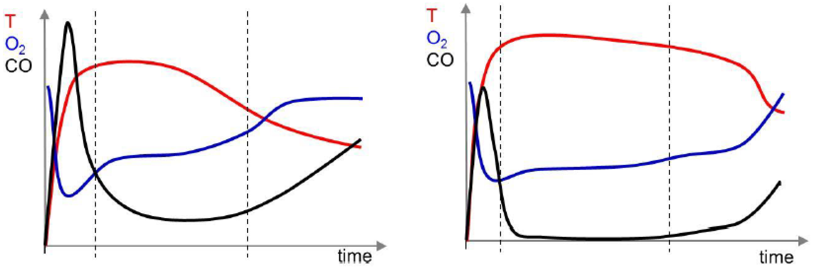
Figure 8.
The software regulation concept of the integrated automatic combustion air regulation system based on flue gas temperature and residual oxygen measurements (O2). The color of the type of combustion air (here: primary air supply via grate, secondary air supply as window purge air and tertiary air from nozzles on the back wall of the combustion chamber) indicates the amount of air introduced. Red: high amount, orange: low amount, black: closed. [53]. Reprint with permission from J.B. Illerup, B.B. Hansen, W. Lin, J. Nickelsen, V.H. Pedersen, B. Eskerod, K. Dam-Johansen, Performance of an automatically controlled wood stove: Thermal efficiency and carbon monoxide emissions, Renewable Energy, Volume 151, 2020, Pages 640–647; Copyright 2020, Elsevier.
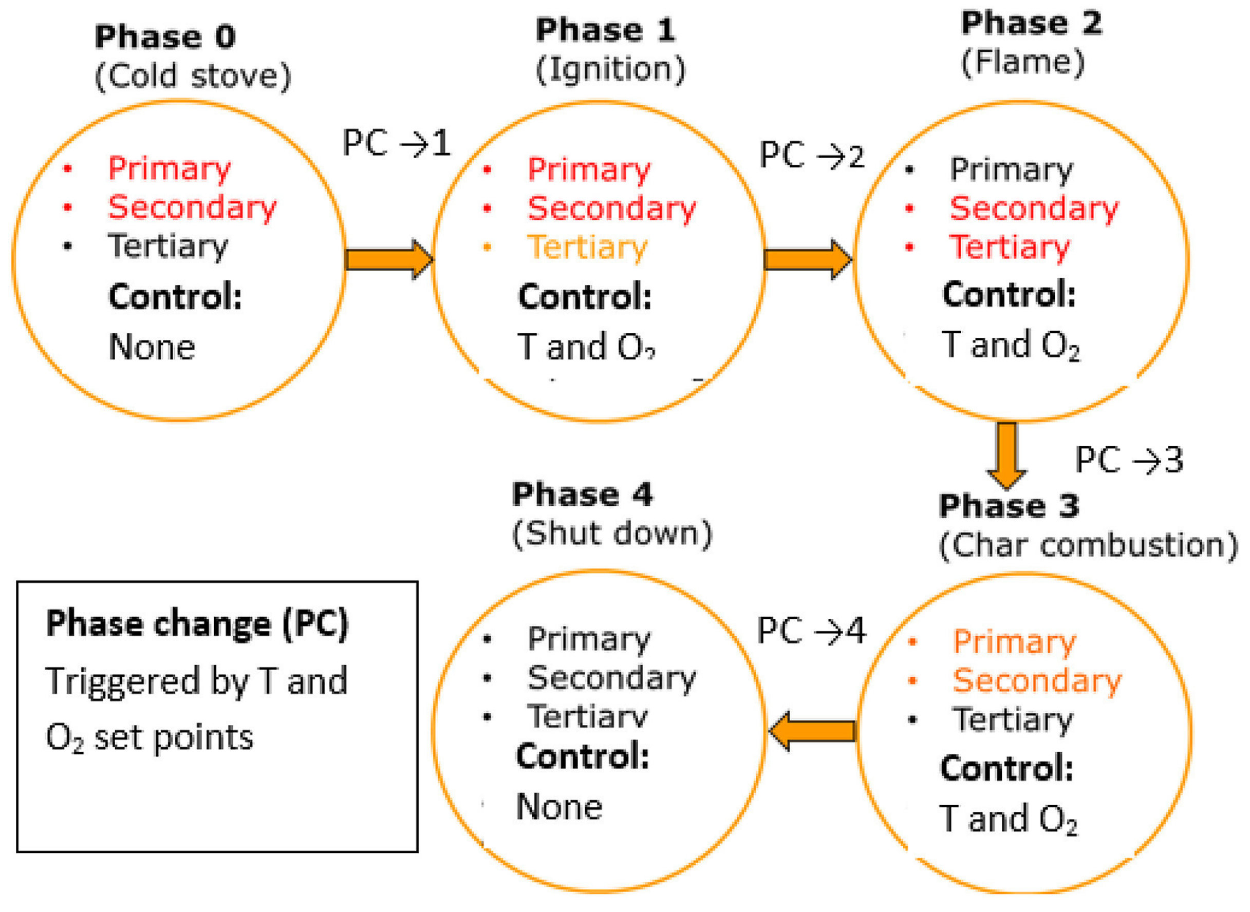
Figure 9.
Schemes of combustion principles regarding primary air supply (white arrow) and flue gas pathways (black arrow) [37]. Reprint with permission from Gaderer, M. et al. (2016). Direkte thermo-chemische Umwandlung (Verbrennung). In: Kaltschmitt, M., Hartmann, H., Hofbauer, H. (eds) Energie aus Biomasse; Copyright 2016, Springer Vieweg, Berlin, Heidelberg. Burn-through combustion principle (a); Top-down combustion principle (b); Bottom-up or downdraft combustion principle (c).

Figure 11.
Packing module integrated in a slow-heat-release appliance between the main and post-combustion chamber [60] (translated into English). Reprint with permission from M. Aleysa, P. Leistner, Verbesserung des Verbrennungs- und Emissionsverhaltens in biomassebetriebenen Einzel-raumfeuerungsanlagen durch den Einsatz spezieller Einbauten; Copyright 2016, Fraunhofer Institute for Building Physics (IBP).

Figure 12.
Particles agglomerated on the surface area of the packing technology [60,61]. (Left): Reprint with permission from M. Aleysa, P. Leistner, Verbesserung des Verbrennungs- und Emissionsverhaltens in biomassebetriebenen Einzel-raumfeuerungsanlagen durch den Einsatz spezieller Einbauten; Copyright 2016, Fraunhofer Institute for Building Physics (IBP). (Right): Reprint with permission from M. ALEYSA, Packing technology for emission reduction in wood-burning stoves and biomass boilers, in: Thomas Nussbaumer (Hrsg.), 15. Holzenergie-Symposium: Netzintegration, Vorschriften und Feuerungstechnik., Tagung an der ETH Zürich am 14. September 2018, Verenum Zürich 2018; Copyright 2018, Verenum.
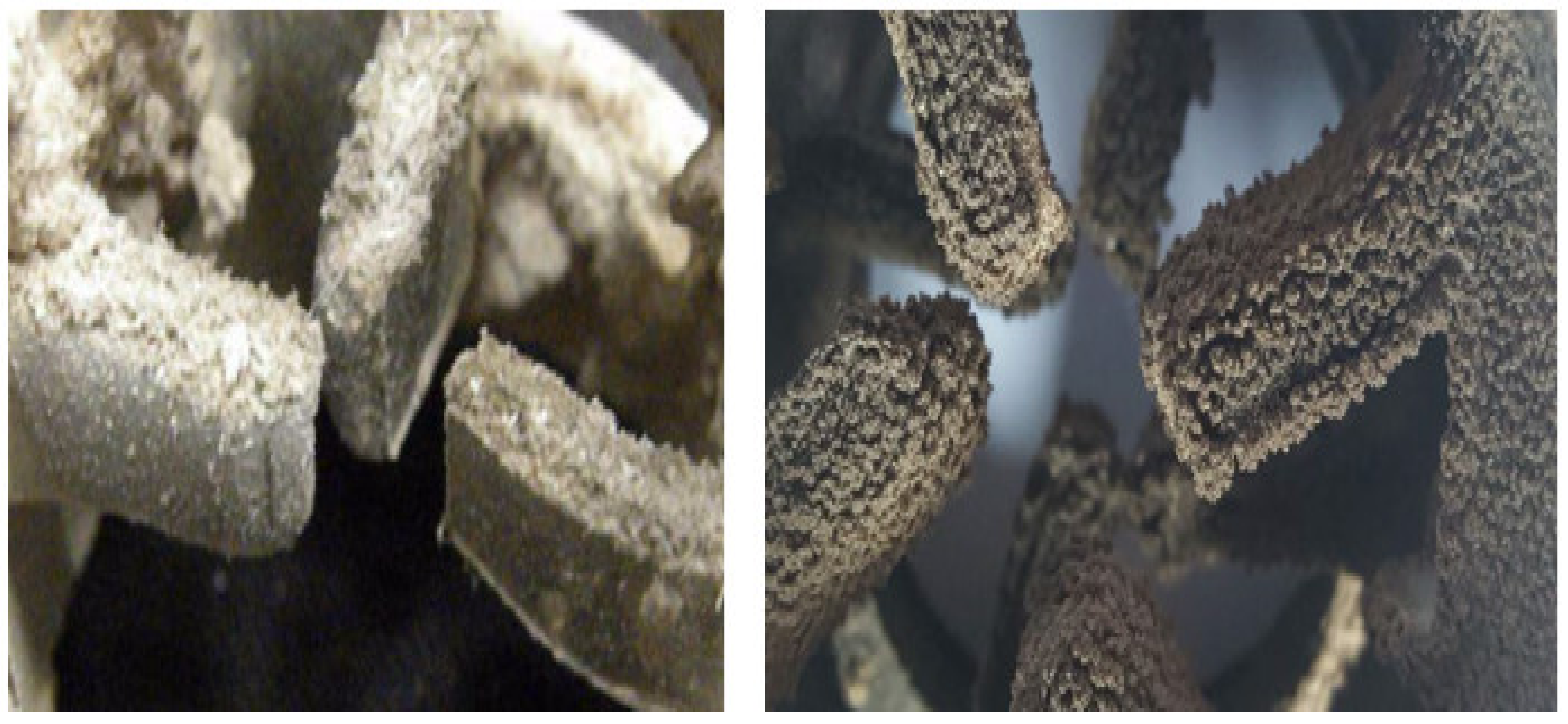
Figure 13.
Comparison of flue gas temperature measurements in a chimney stove (EN 13240) with and without an integrated packing module [60] (translated into English). Reprint with permission from M. Aleysa, P. Leistner, Verbesserung des Verbrennungs- und Emissionsverhaltens in biomassebetriebenen Einzel-raumfeuerungsanlagen durch den Einsatz spezieller Einbauten; Copyright 2016, Fraunhofer Institute for Building Physics (IBP).

Figure 14.
General reaction mechanism of an exothermic reaction (X + Y → Z) with and without catalyst [63]. Copyright 2008, Attribution: No machine-readable author provided. Smokefoot assumed (based on copyright claims). Public domain via Wikimedia Commons.
Figure 14.
General reaction mechanism of an exothermic reaction (X + Y → Z) with and without catalyst [63]. Copyright 2008, Attribution: No machine-readable author provided. Smokefoot assumed (based on copyright claims). Public domain via Wikimedia Commons.
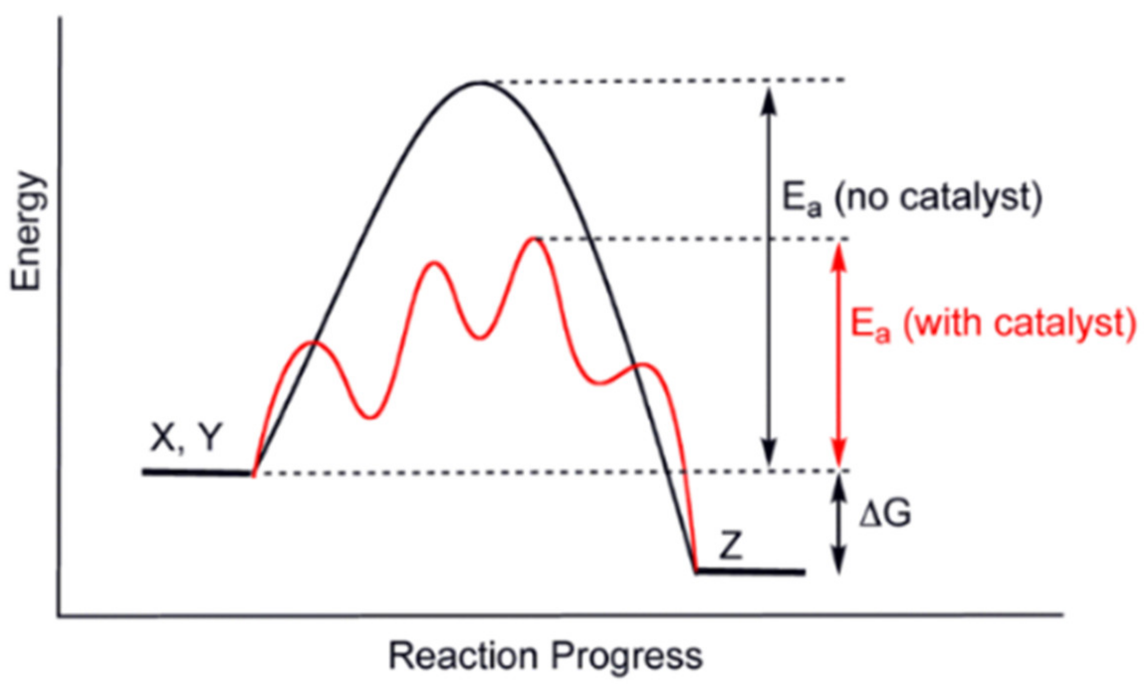
Figure 15.
Honeycomb catalyst with ceramic carrier (a) [47] and catalytic foamed ceramic (b) [25]. (a) Reprint with permission from G. Reichert, Primary- and Secondary Measures for Manually Fired Stoves – An Overview. 6th Central European Biomass Conference, 2020, Austria, Graz; Copyright 2020, BEST GmbH. (b) Reprint with permission from R. Mack, D. Kuptz, C. Schön, H. Hartmann, Optimierungspotenziale bei Kaminöfen, Berichte aus dem TFZ, Nr. 57, Technologie- und Förderzentrum im Kompetenzzentrum für Nachwachsende Rohstoffe (TFZ), Straubing, 2018, p. 116. Copyright 2018, Technologie- und Förderzentrum (TFZ).
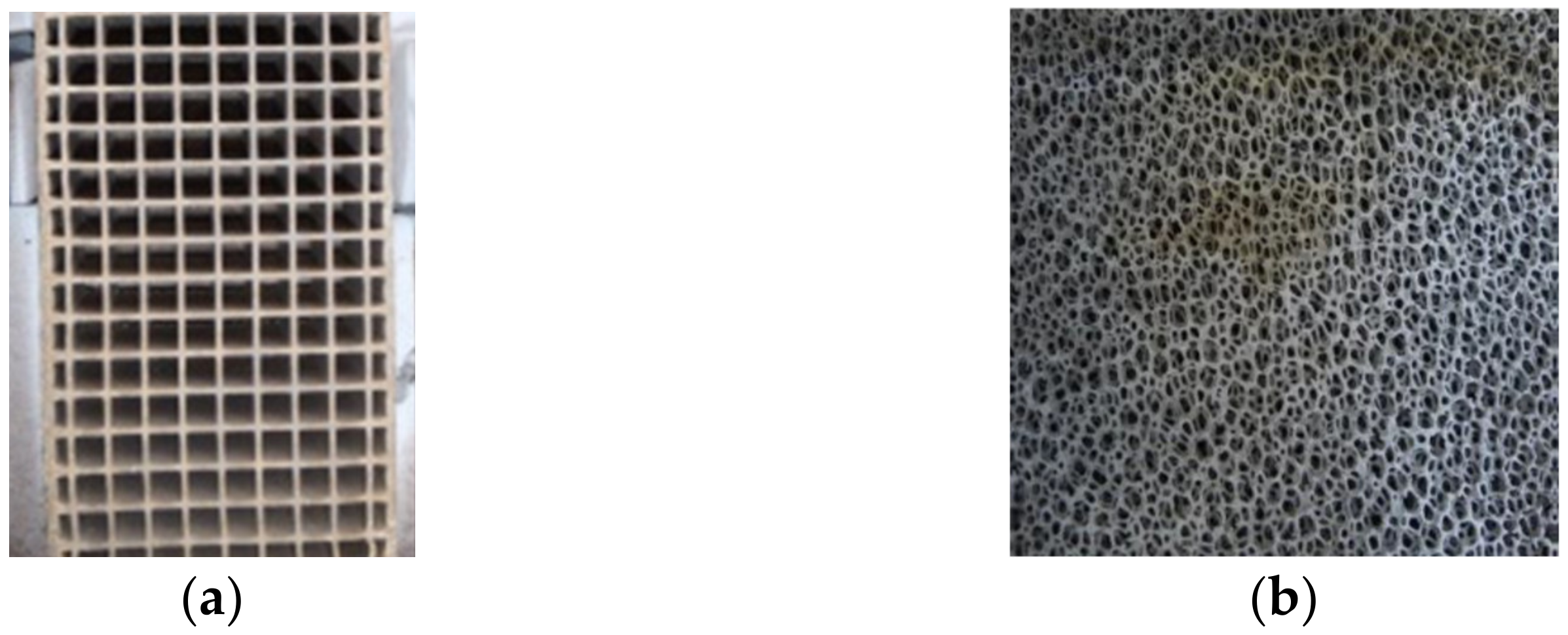
Figure 16.
Construction design of a honeycomb catalyst and characteristics of a catalytic reaction. Own figure based on [65].
Figure 16.
Construction design of a honeycomb catalyst and characteristics of a catalytic reaction. Own figure based on [65].
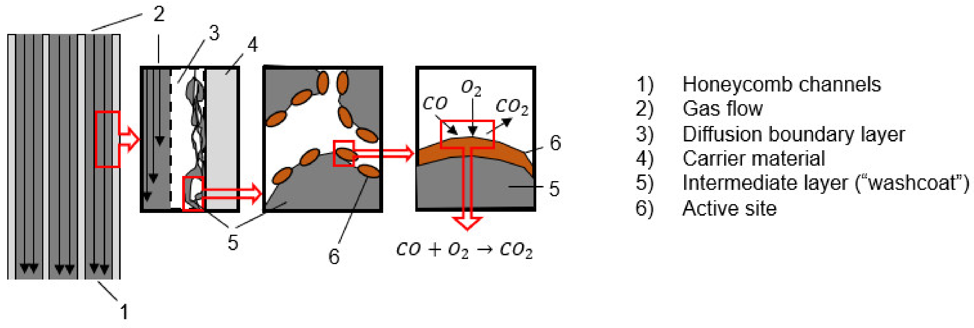
Figure 18.
Average emissions with catalyst integrated solutions (ceramic and metallic catalytic honeycomb catalysts). Dashed lines represent the ELV of Ecodesign requirements for firewood stoves coming into force in 2022 [68]. Reprint with permission from G. Reichert, C. Schmidl, W. Haslinger, H. Stressler, R. Sturmlechner, M. Schwabl, M. Wöhler, C. Hochenauer, Impact of oxidizing honeycomb catalysts integrated in firewood stoves on emissions under real-life operating conditions, Fuel Processing Technology, Volume 177, 2018, Pages 109–118; Copyright 2018, Elsevier.
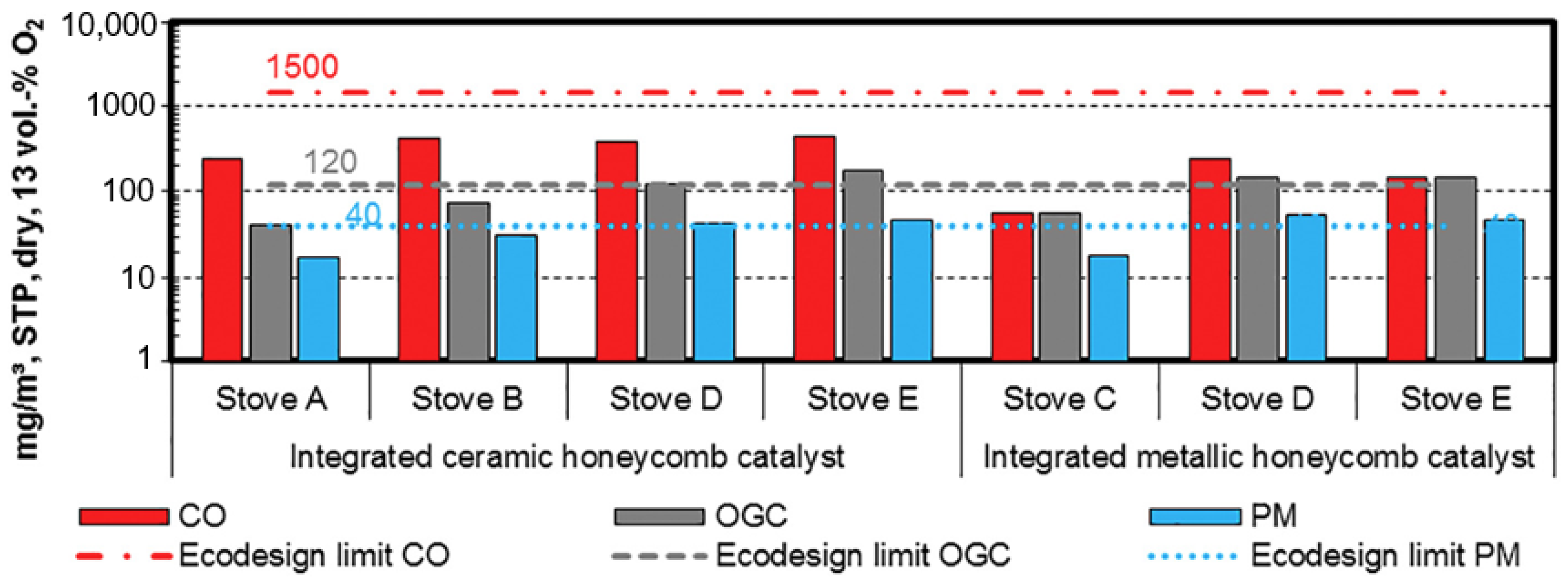
Figure 20.
PM emission conversion efficiencies of different separation technologies by particle size [37] (translated into English). Reprint with permission from Gaderer, M. et al. (2016). Direkte thermo-chemische Umwandlung (Verbrennung). In: Kaltschmitt, M., Hartmann, H., Hofbauer, H. (eds) Energie aus Biomasse; Copyright 2016, Springer Vieweg, Berlin, Heidelberg.

Figure 21.
Principle of particle separation by using electrostatic precipitators (ESP) [37] (translated into English). Reprint with permission from Gaderer, M. et al. (2016). Direkte thermo-chemische Umwandlung (Verbrennung). In: Kaltschmitt, M., Hartmann, H., Hofbauer, H. (eds) Energie aus Biomasse; Copyright 2016, Springer Vieweg, Berlin, Heidelberg.
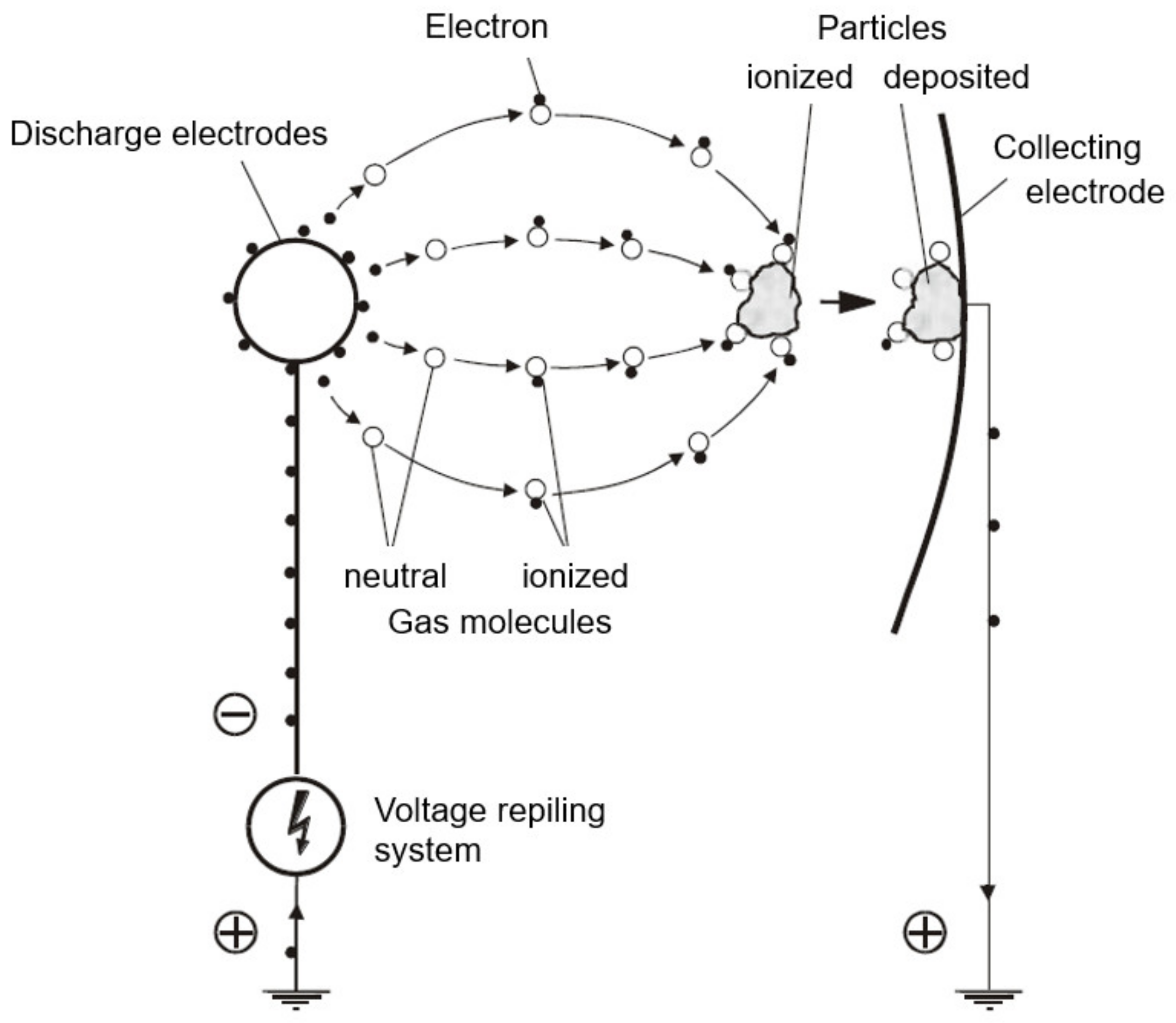
Table 1.
Average results of three tests according to top-down and bottom-up ignition techniques.
| Ignition Technique | Reference | Stove | Draught | CO * | VOC * | PM * |
|---|---|---|---|---|---|---|
| Top-down | [7,8] | “Sino L” of Spartherm Feuerungstechnik GmbH | Natural | 4111 | 847 | 73 |
| controlled (12 Pa) | 2667 | 352 | 69 | |||
| Bottom-up | Natural | 2761 | 328 | 66 | ||
| controlled (12 Pa) | 1870 | 151 | 61 | |||
| Top-down | [10] | Chimney stove (A) acc. to EN 13240 | Controlled (12 Pa) | 2732 | 362 | 100 |
| Bottom-up | Controlled (12 Pa) | 2092 | 381 | 78 | ||
| Top-down | Chimney stove (B) acc. to EN 13240 | Controlled (12 Pa) | 747 | 38 | 69 | |
| Bottom-up | Controlled (12 Pa) | 1642 | 159 | 66 | ||
| Top down | [23] | WABI (D2I INVICTA, DONCHERY, FRANCE) | Controlled (12 Pa) | 2193 | 210 | 48.8 |
| Bottom-up (traditional campfire) | Controlled (12 Pa) | 4696 | 326 | 72.1 |
* STP: 0 °C, 1.013 bar; dry flue gas; referred to 13 vol.-% O2.
Table 3.
Results of experimental lab tests with and without integrated packing technology in two different types of firewood room-heating appliances (best-practice heating operation mode using beech firewood) [60].
Table 3.
Results of experimental lab tests with and without integrated packing technology in two different types of firewood room-heating appliances (best-practice heating operation mode using beech firewood) [60].
| Stove | Packing Technology | CO * | VOC * | PM * |
|---|---|---|---|---|
| EN 13240 chimney stove | Without | 1356 | 122 | 32-68 |
| Metallic | 791 | 32 | 17 | |
| Ceramic | 379 | 16 | 11 | |
| EN 15250 slow-heat-release appliance | Without | 1934 | 273 | 46 |
| Metallic | 790 | 36 | 13 | |
| Ceramic | 578 | 37 | 10 |
* mg/m³, STP: 0 °C, 1.013 bar; referred to 13 vol.-% O2.
Table 4.
Results of conversion efficiencies of experimental lab tests using an integrated honeycomb catalyst or catalytic foamed ceramic without any bypass (Equation (3)) [64].
Table 4.
Results of conversion efficiencies of experimental lab tests using an integrated honeycomb catalyst or catalytic foamed ceramic without any bypass (Equation (3)) [64].
| Secondary Measure | CO | VOC | PM |
|---|---|---|---|
| Honeycomb catalyst (metallic carrier, active sites Pt, Pd) | 70% | 55% | 27% |
| Foamed ceramic (catalytic, active sites: Pt, Pd, Rh) | 20%³ | 31% | 29% |
Table 5.
Results of field measurements on two SHRA during ON and OFF periods of ESPs installed on the roof of the buildings within the chimney system [85].
Table 5.
Results of field measurements on two SHRA during ON and OFF periods of ESPs installed on the roof of the buildings within the chimney system [85].
| Type of stove | SHRA (8kW) | SHRA (10kW) |
|---|---|---|
| Installation year | 2004 | 2017 |
| Ø chimney (mm) | 150 | 180 |
| Voltage (kV) | 30 | 30 |
| Current (µA) | 21 | 39 |
| PM (ESP ON) * | 21 | 39 |
| PM (ESP OFF) * | 147 | 98 |
| Conversion efficiency () | 86% | 60% |
* mg/m³, STP: 0 °C, 1.013 bar; referred to 13 vol.-% O2.
Table 6.
SWOT analysis of non-technical primary measures: general information about “correct heating”, hands-on user training, quick user guide.
Table 6.
SWOT analysis of non-technical primary measures: general information about “correct heating”, hands-on user training, quick user guide.
| Strengths | Weaknesses |
|---|---|
|
|
| Opportunities | Threats |
|
|
Table 7.
SWOT analysis of technical primary measures: air supply and air staging concept, combustion chamber design, draught control and automatic combustion air regulation devices.
Table 7.
SWOT analysis of technical primary measures: air supply and air staging concept, combustion chamber design, draught control and automatic combustion air regulation devices.
| Strengths | Weaknesses |
|---|---|
|
|
| Opportunities | Threats |
|
|
Table 8.
SWOT analysis of secondary measures: packing technology (oxidizing reactors), catalysts, fabric baghouse filters, electrostatic precipitators (ESP).
Table 8.
SWOT analysis of secondary measures: packing technology (oxidizing reactors), catalysts, fabric baghouse filters, electrostatic precipitators (ESP).
| Strengths | Weaknesses |
|---|---|
|
|
| Opportunities | Threats |
|
|
Table 9.
Qualitative evaluation of potential combinations of primary measures and secondary technologies (red: negative; green: positive; yellow: neutral).
Table 9.
Qualitative evaluation of potential combinations of primary measures and secondary technologies (red: negative; green: positive; yellow: neutral).
| Combination | CO/VOC | PM | Natural Draught | Costs of Secondary Measure |
|---|---|---|---|---|
| Primary measures * and packing technology | ||||
| Primary measures * and catalysts | ||||
| Primary measures * and ESP | ||||
| Primary measures * and fabric baghouse filter | ||||
| Primary measures *, packing technology and fabric baghouse filter | ||||
| Primary measures *, catalyst and fabric baghouse filter | ||||
| Primary measures *, catalyst and ESP | ||||
| Primary measures *, packing technology and ESP |
* Primary measures cover appropriate air supply and air staging, combustion chamber design, draught control and automatic combustion air regulation devices (integrated application) (technical primary measure), as well as best-practice heating operation (non-technical primary measure).
Disclaimer/Publisher’s Note: The statements, opinions and data contained in all publications are solely those of the individual author(s) and contributor(s) and not of MDPI and/or the editor(s). MDPI and/or the editor(s) disclaim responsibility for any injury to people or property resulting from any ideas, methods, instructions or products referred to in the content. |
© 2023 by the authors. Licensee MDPI, Basel, Switzerland. This article is an open access article distributed under the terms and conditions of the Creative Commons Attribution (CC BY) license (https://creativecommons.org/licenses/by/4.0/).
Share and Cite
MDPI and ACS Style
Reichert, G.; Schmidl, C. SWOT Analysis of Non-Technical and Technical Measures towards “(Nearly) Zero-Emission Stove Technologies”. Energies 2023, 16, 1388. https://doi.org/10.3390/en16031388
AMA Style
Reichert G, Schmidl C. SWOT Analysis of Non-Technical and Technical Measures towards “(Nearly) Zero-Emission Stove Technologies”. Energies. 2023; 16(3):1388. https://doi.org/10.3390/en16031388
Chicago/Turabian StyleReichert, Gabriel, and Christoph Schmidl. 2023. "SWOT Analysis of Non-Technical and Technical Measures towards “(Nearly) Zero-Emission Stove Technologies”" Energies 16, no. 3: 1388. https://doi.org/10.3390/en16031388
Note that from the first issue of 2016, this journal uses article numbers instead of page numbers. See further details here.