Article

Performance Enhancement of an Islanded Microgrid with the Support of Electrical Vehicle and STATCOM Systems

by
Omar Makram Kamel
1,
Ahmed A. Zaki Diab
2,*,
Mohamed Metwally Mahmoud
3,
Ameena Saad Al-Sumaiti
4,* and
Hamdy M. Sultan
2,*
1
Electrical and Computer Department, Higher Institute of Engineering and Technology New El Minia, Minia 61111, Egypt
2
Department of Electrical Engineering, Faculty of Engineering, Minia University, Minia 61517, Egypt
3
Department of Electrical Engineering, Faculty of Energy Engineering, Aswan University, Aswan 81528, Egypt
4
Department of Electrical Engineering and Computer Science, Advanced Power and Energy Center, Khalifa University, Abu Dhabi 127788, United Arab Emirates
*
Authors to whom correspondence should be addressed.
Energies 2023, 16(4), 1577; https://doi.org/10.3390/en16041577
Submission received: 9 December 2022 / Revised: 14 January 2023 / Accepted: 18 January 2023 / Published: 4 February 2023
(This article belongs to the Special Issue Design, Planning and Evaluation of Flexible Power Systems)

Abstract

:
Modern electrical power systems now require the spread of microgrids (MG), where they would be operating in either islanded mode or grid-connected mode. An inherent mismatch between loads and sources is introduced by changeable high renewable share in an islanded MG system with stochastic load demands. The system frequency is directly impacted by this mismatch, which can be alleviated by incorporating cutting-edge energy storage technologies and FACTS tools. The investigated islanded MG system components are wind farm, solar PV, Electric vehicles (EVs), loads, DSTATCOM, and diesel power generator. An aggregated EVs model is connected to the MG during uncertain periods of the generation of renewable energy (PV and wind) to support the performance of MGs. The ability to support ancillary services from the EVs is checked. DSTATCOM is used to provide voltage stability for the MG during congestion situations. The MG is studied in three scenarios: the first scenario MG without EVs and DSTATCOM, the second scenario MG without DSTATCOM, and the third scenario MG with all components. These scenarios are addressed to show the role of EVs and DSTATCOM, and the results in the third scenario are the best. The system voltage and frequency profile is the best in the last scenario and is entirely satisfactory and under the range of the IEEE standard. The obtained results show that both EVs and DSTATCOM are important units for improving the stability of modern power grids. The Matlab/Simulink program is considered for checking and validating the dynamic performance of the proposed configuration.

1. Introduction

The environmental impacts of conventional power sources have led to the harnessing of renewable energy sources [1,2,3], while the demand growth has led to the implementation of a larger number of stations. The major point is cost-effectiveness. In this context, the changing system moved from a centralized grid structure into a distributed structure, where power generation and consumption happen in the same area. Moreover, the challenge of assuring service reliability mandates the grid’s robustness with less dependency on centralized generation [4,5,6].
Microgrid (MG) is a novel idea in the intellectual community that combines several energy sources, including electricity, heat, hydrogen, renewable energy, and natural gas [7,8]. From the perspective of the customer, MGs are comparable to conventional local voltage distribution networks in that they not only meet their thermal and electricity needs but also improve local reliability, cut emissions, enhance power quality by supporting voltage and minimizing voltage dips, and lower energy supply costs. To have a substantial future impact on power networks in a short time, MGs should make use of a variety of renewable energy sources (e.g. wind, solar, hydrogen, etc.) [9,10,11].
To guarantee optimal dynamic performance, governments worldwide are implementing policies integrating more MGs into conventional power grids. These policies ensure the large penetration of a variety of technologies (e.g. renewable energy technologies, electrical vehicle (EV) grid, and intelligent houses in the power network) [12,13]. The complicated infrastructure of MGs is the main issue that restricts their integration. Therefore, new technical challenges should be addressed to plan, operate, and control MG [14,15].
EVs can be categorized as electric vehicles with controlled loads. According to studies, EVs are not used for active transportation more than 90% of the time. Batteries from EVs can therefore be used to supply the electrical market during these times [16,17]. The EVs are a variable load during charging and are a clean energy source during discharging. It is unpredictable how many will be present in a particular area at a given moment, which results in erratic grid performance. Since MGs have a dynamic structure and a range of operating situations, it is clear that the development of adaptive protection solutions and an adequate load management system is required [18,19].
Many studies have focused on the MG’s small signal stability, transient stability, and stability improvement methodologies. The supply chain’s dependability and optimal security design considering MG stability can improve the system [20,21,22]. According to [23,24], the stability issue for islanded MGs is classified into load class and fault class. Both types are investigated in this work. Investigating the stability issue of the MGs is a vital point of research that helps in designing the protection systems for either the MGs or connecting inverter-based diesel generators (DG) to conventional power grids.
Various strategies have been used to increase MG stability. The major methods are focused on enhancing control strategies of shading load control concepts and reactive power compensation techniques [25,26,27]. When the larger generator is lost, a backup energy storage supply is inserted for the load shading process. EVs nowadays are integrated into the electric networks in abundance to decrease the impact of greenhouse gases. EVs can supply the islanded MG with the required power level during such congestion situations; however, adequate communication is needed to coordinate [28]. In an MG, reactive power compensation is another technique to increase stability by keeping the voltage within acceptable limits when strongly balanced and unbalanced utility voltage sags occur. FACTS can improve the ride-through capability by injecting the required reactive power [29,30,31].
The study presents a hybrid islanded MG model considering several sustainable energies (wind and PV) and the integration of both EVs and STATCOM. The system loads are residential. This work aims to achieve frequency and voltage stability under harsh operating scenarios with the support of EVs and DSTATCOM. The proposed MG performance is investigated during 8 h of operation, representing the higher load demand period. Intermittent renewable energy systems (wind/solar PV) normally work at fixed power factors. In other words, these energy units absorb reactive power from the grid utility instead of producing. Hence, reactive power based on power electronics supports the voltage regulation of these new systems. The stability performance is enhanced using DSTATCOM as one of the most effective FACTS devices.
The organization of the rest of this paper is as follows: The modeling and configurations of the studied system components are established in Section 2. The MG stability is presented in Section 3. The application and modeling of DSTATCOM in MG are introduced in Section 4. The simulation studies and conclusions are set in Section 5 and Section 6, respectively.

2. System under Study

As shown in Figure 1, the MG is composed of four major components: a DG operating as the main source of power supply in the grid, a PV power plant paired with a wind turbines farm for providing the share of renewable power, and a vehicle to grid (V2G) component situated near the grid load. The size of the MG corresponds to roughly a thousand farmers. In the model, 100 EV exists, representing a ratio of (1/10) when comparing vehicles to homes. This scenario may occur in the near future.
The DG can contribute to balancing the power consumed and generated [32,33].
In this MG, renewable energy is provided by two different sources. There are multiple factors that influence the total energy produced from the PV farm. These factors include the area size that PV modules cover, PV modules’ efficiency, and solar irradiance statistics. The wind farm produces a nominal amount of power when the wind is at a specific threshold. At the maximum wind speed for the wind turbine, the wind farm will be disconnected from the power network and will then be connected if the wind speed decreases below the cut-off speed.
To represent the residential load, an asynchronous machine is utilized to simulate the effect of loads of inductive nature at industries in the MG (e.g. ventilation system); its rated value is 0.16 MVA. The residential load power is 10 MW at 0.95 PF, and the rated load bus voltage is (V-B2) 500 V. The generator bus voltage V-B2 is 25 kV.
The V2G concept is deployed for the management of power exchange among EVs and MG’s sources of energy. The available power through the EVs to under-off operation can be regulated to the grid. This function can be harnessed as an ancillary service (AS) for the MG during uncertain conditions.

2.1. Diesel Generator Model

The DG is a traditional generating unit used in hybrid energy systems as a backup source. The DG will be in service when the power generated from renewable sources, i.e., PV and wind farms, is less than the demand load, and at the same time, the batteries are completely discharged. The fuel consumption of the diesel generator, D f ( t ) , can be calculated as the following [34]:
D f ( t ) = α D G P D G ( t ) + β D G P D G R ,  
where P D G ( t ) and P D G R are the average output power and rated power of the DG, respectively, and α D G & β D G present the coefficients of the fuel consumption curve of the DG. Based on [19], the values of these coefficients, which have been considered in the present study, are 0.246 and 0.08145 for α D G and β D G , respectively [34].

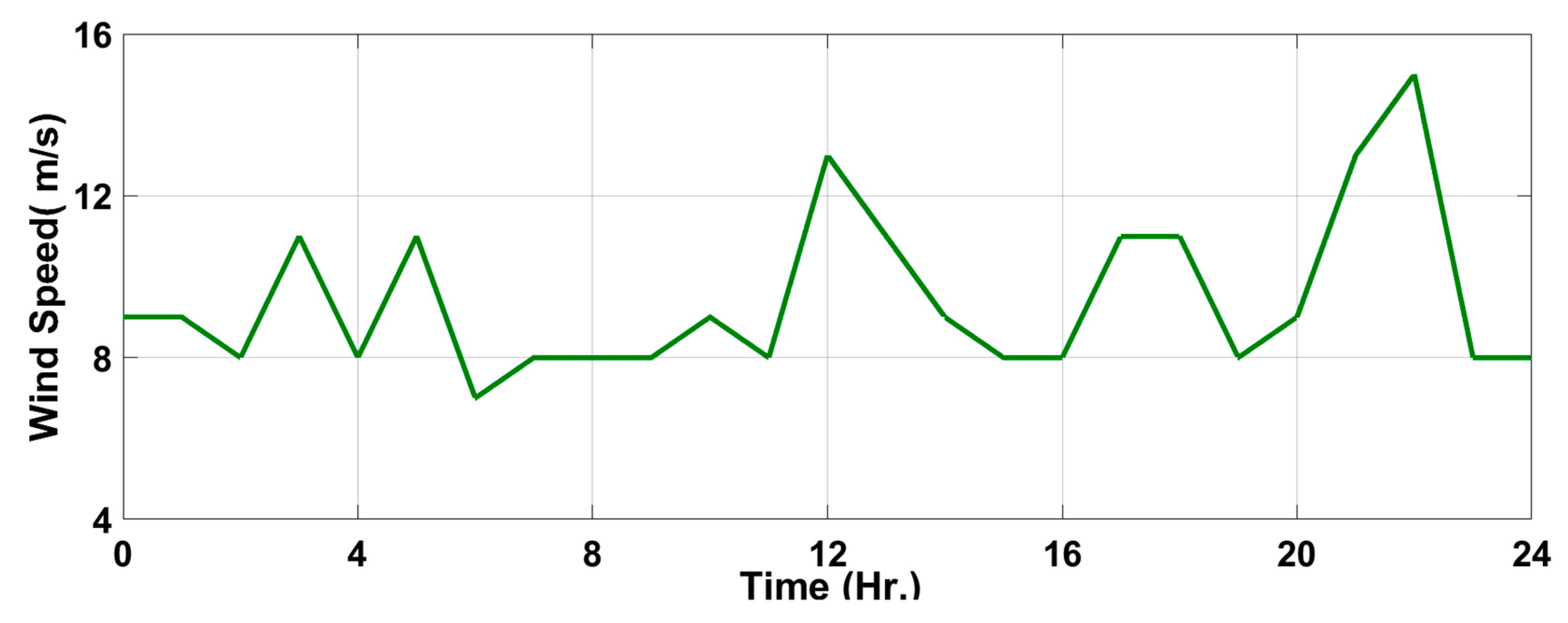
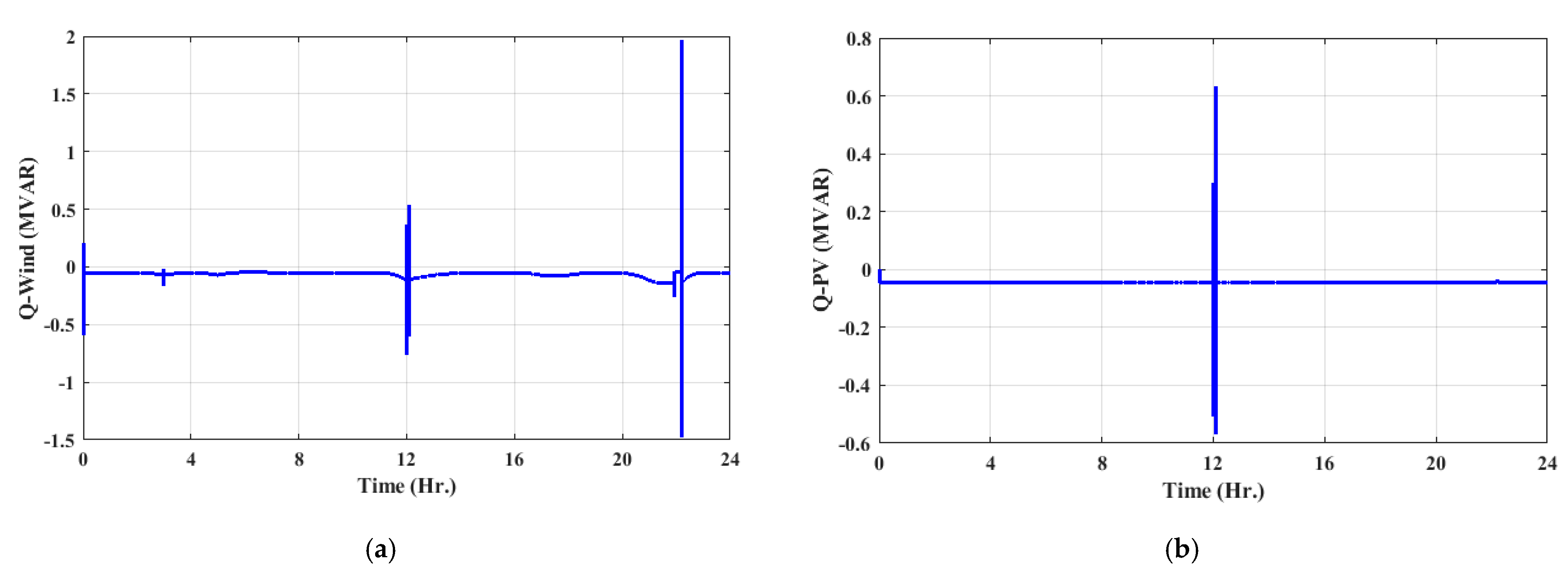
2.2. Modelling of Wind Turbine System

Both wind speed and wind turbine’s hub height characteristics are the significant influencing causes for generating the output power from wind turbines, which can be calculated from this equation [34,35,36].
V 2 = V 1   ( H 2 H 1 ) β W T
where V 1 and V 2 are the measured wind speed at the reference point (H1) and hub height (H2), respectively; β W T is the friction coefficient and its value (0.143) for low roughness [34,36].
The output power generated from the wind turbine can be determined as follows:
P w ( t ) = η w P r _ w * V 2 ( t ) V c i n 2 V r 2 V c i n 2 V c _ i n < V ( t ) < V r r η w P w r V r < V ( t ) < V c _ o f f 0 V ( t ) < V c _ i n or V ( t ) < V c _ o f f ,
where η w is the efficiency of the wind energy system, P r _ w presents the rated power of the wind turbine, V c _ i n is the cut-in speed at which the wind turbine starts generating electric energy, V r is the rated wind speed of the wind turbine, and V c _ o f f presents the cut-off speed, after which the wind turbine will be shut off to prevent mechanical damage. The total output power produced by a group of wind turbines is calculated as follows:
P tot _ w = N w ×   P w   ( t )

2.3. Solar Energy Model

The optimal operating point current I p v and voltage V p v that maximize the generated power at each instant can be calculated as follow:
I p v ( t ) = I s c , r e f { 1 A [ e x p ( V m p , r e f B V o c , r e f ) 1 ] } + Δ I ( t )
V p v ( t ) = V m p , r e f [ 1 + 0.0539 l o g ( G i n ( t ) G ST ) ] + μ Δ T ( t )
where
A = ( 1 I m p , r e f I s c , r e f ) e x p [ V m p , r e f B V o c , r e f ]
B = V m p , r e f V o c , r e f 1 l n ( 1 I m p , r e f I s c , r e f )
Δ I ( t ) = γ ( G i n ( t ) G s t ) Δ T ( t ) + ( G i n ( t ) G s t 1 ) I s c , r e f
Δ T ( t ) = T a m b + 0.02 G i n ( t )
where I s c , r e f and I m p , r e f are the short circuit current and current at the maximum power of the modules, respectively. V m p , r e f and V o c , r e f are the module’s voltage at the maximum power point and open circuit voltage, respectively. G i n and G ST are the total irradiance fallen on a tilted surface and standard irradiance intensity (1000 W/m2).
Output voltage and power generated from the PV modules can be calculated by:
V p v , o u t ( t ) = β p v , s V p v ( t )
u p v ( t ) = β p v , s β p v , p V p v ( t ) I p v ( t ) ξ l o s s
where β p v , s and β p v , p are the number of modules in the series and parallel strings of the PV array, respectively. ξ l o s s denotes a factor representing loss due to connection and other losses caused by accumulative dust, etc. The output power of PV modules is proportional to solar radiation, temperature, and geographical locations [34]. The amount of power can be calculated by:
P p v ( t ) = P r p v η p v η w i r e I ( t ) 1000 ( 1 λ T ( T a m + ( N O C T 20 ) 800   I a m ( t ) 25 ) )
where n p v and P r _ p v are the number of PV modules and the maximum power of the PV module, respectively,   η w i r e and η p v are the wiring efficiency and the efficiency of the PV module, respectively,   λ T is the temperature coefficient of the PV module, and finally, I a m ( t ) is the ambient of solar radiation. The total output power produced from solar PV cells is calculated as follows:
P tot _ p v ( t ) = N p v × P p v ( t ) ,

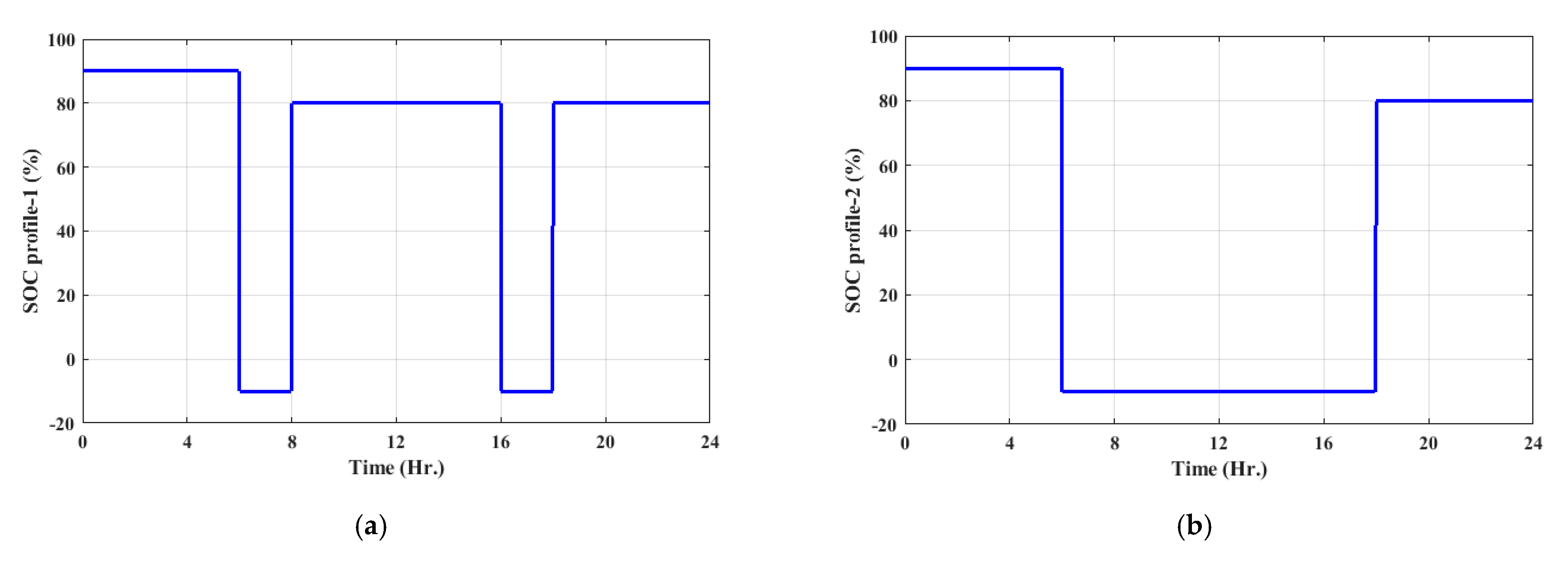
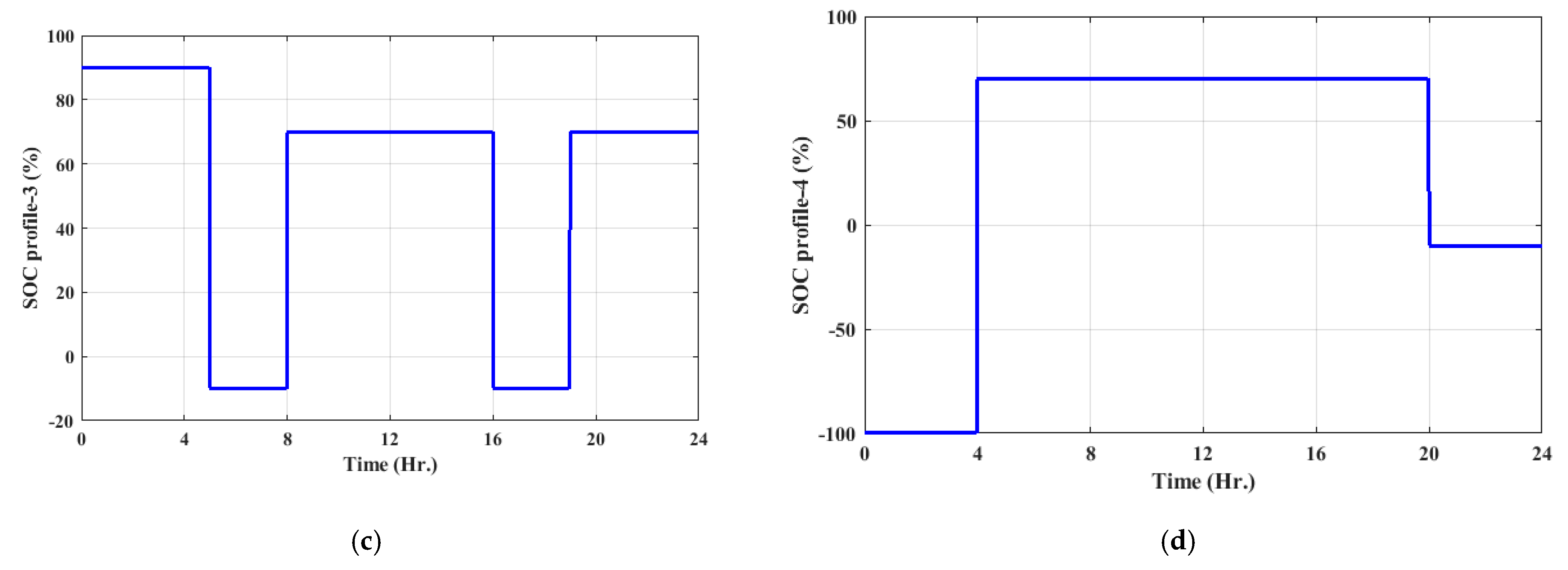
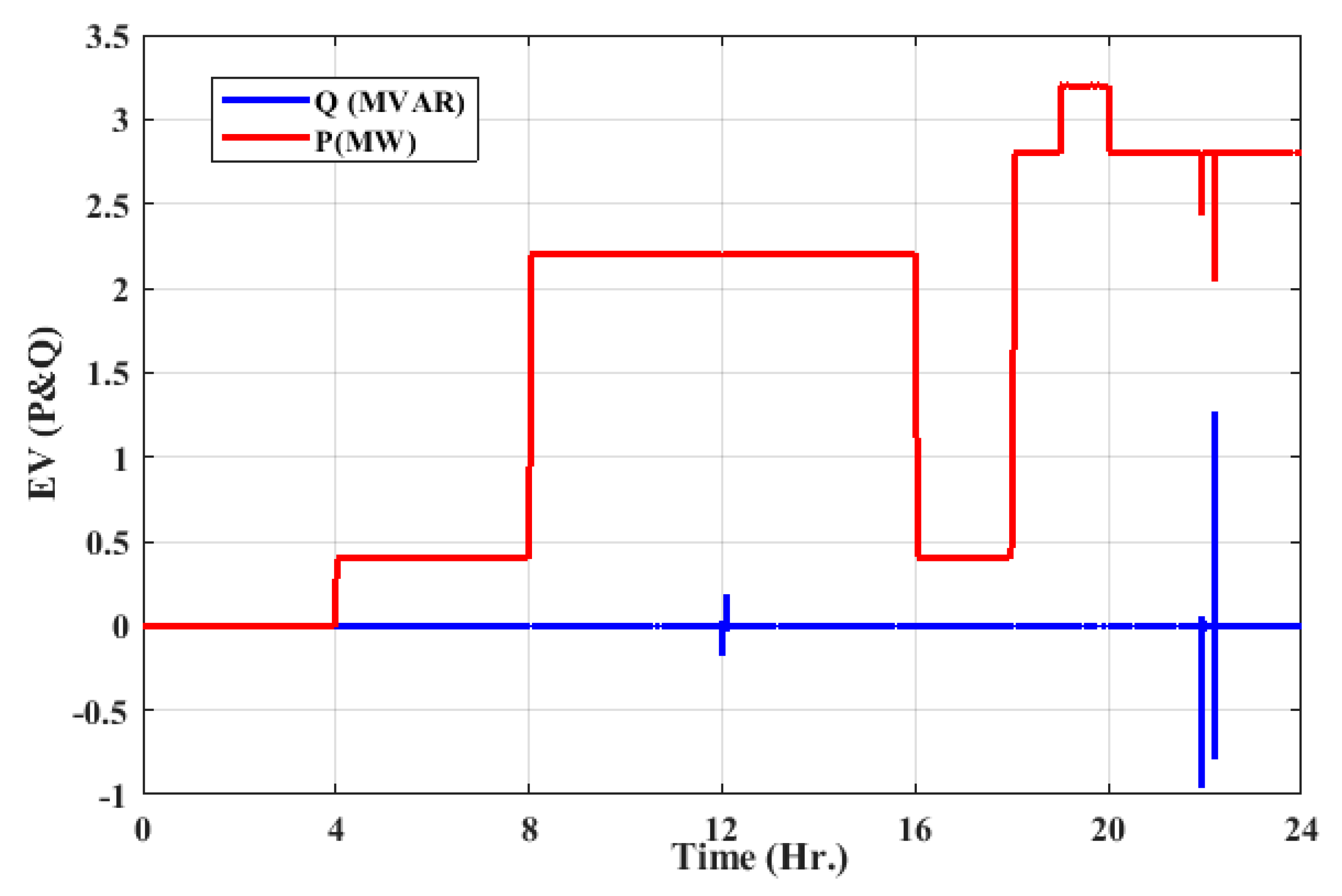
2.4. Electrical Vehicle Model

The V2G system indicates the interaction between the power grid and EV. It can behave like a variable load. During the uncertain periods of renewable power sources, they can be considered variable energy sources. Hence, EVs can support the MGs with the Ass calling system to be V2G mode of operation. The V2G mode of Evs decreases the implementation of more conventional power plants. During the peak demand periods, it is possible to release the stored power in EVs’ batteries to the grid to guarantee the balance between the load demand and the MGs’ generated power.
For the present paper, a summary of the major distinctive parameters of EVs is provided in Table 1 [37]. The vehicle driving balance formula establishes the model of the EV. Hence, the required EV power (P_req) can be determined as follow:
P r e q = V a 3600 n t ( mgfcos ( α ) + C A V a 2 21.15 + mgsin ( α ) + δ m d V a d t
where Va denotes the speed of the EV, m presents the mass of the EV, A is the windward area, nt denotes the transmission system efficiency, C denotes the coefficient of air resistance, f, δ, g, and α denotes the coefficient of rolling resistance, correction coefficient of the rotation mass, gravity acceleration and the road angel, respectively.

3. Microgrid Stability

One of the challenges facing MG operations is stability issues. Unlike conventional power grids, the stability of MGs depends on the spinning reserve stored on the DGs connected to the grid. Most of the DGs connected to the MGs PV, Wind Farms, Energy storages, etc. are inverter-based DGs [35,38]. According to [39], the time frame of DGs-based inverter interfaced has a faster response than traditional DGs. The balance between the load demand and the DGs is a milestone for islanded MGs.
In most cases, the stability issue of islanded MGs depends on the energy stored in the DGs. During peak shavings, EVs can work as energy storage power sources. Unlike conventional power grids—whose stability depends on the rotor angle performance of the synchronous generator—the MG’s stability is related to small stability and transient stability. Small stability occurs when a variation in load demand or line impedance changes, causing a change in the voltage and frequency of the grid.

4. Application of FACTS in Microgrids

The transient stability is related to large disturbances such as short or open circuit faults and losing large DGs or loads. FACTS can assist the MGs stability problem during voltage dips problems. One of the most promising FACTS devices to assist the stability of MGs is the DSTATCOM [40,41]. It provides a reactive power compensation to obtain stable voltage ride-through for the MGs. Modeling of the DSTACOM and passive filters have been presented in this section.

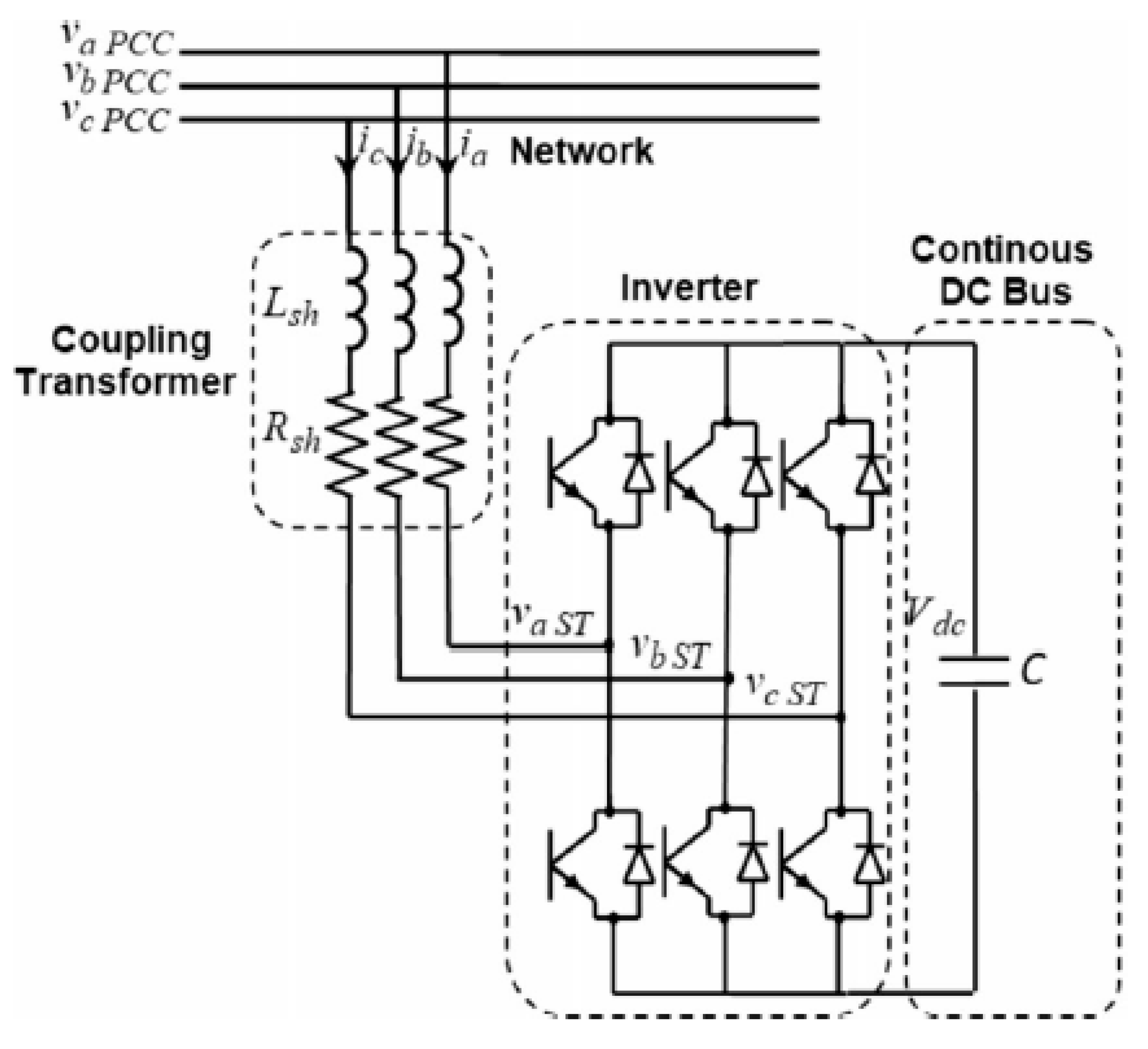
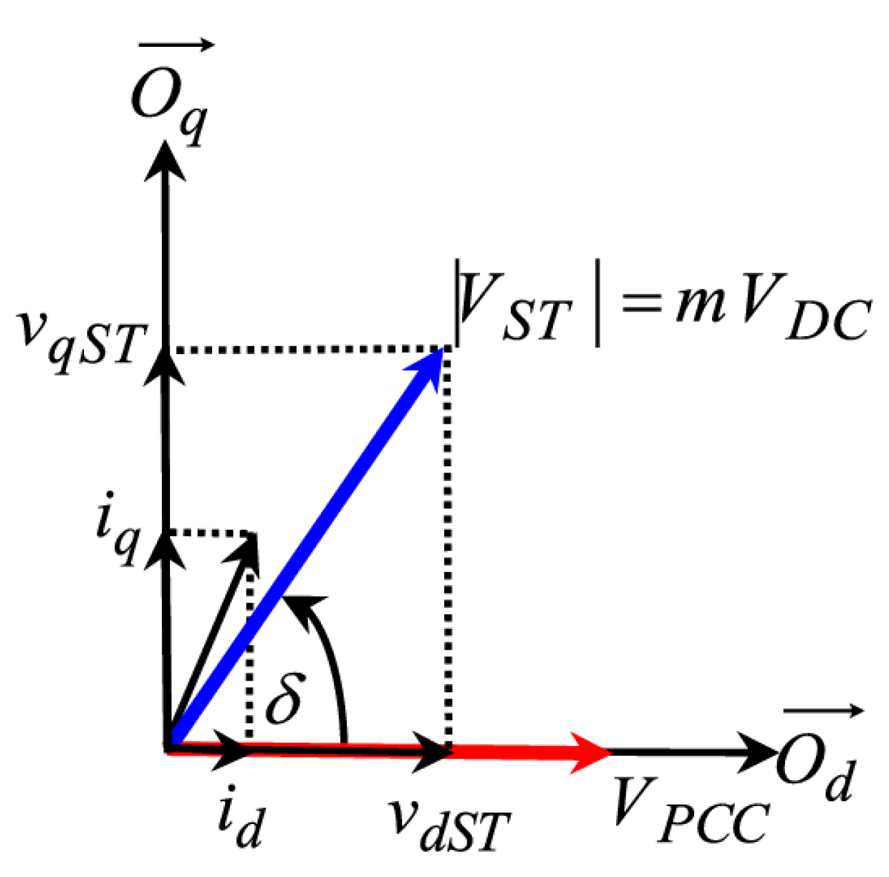
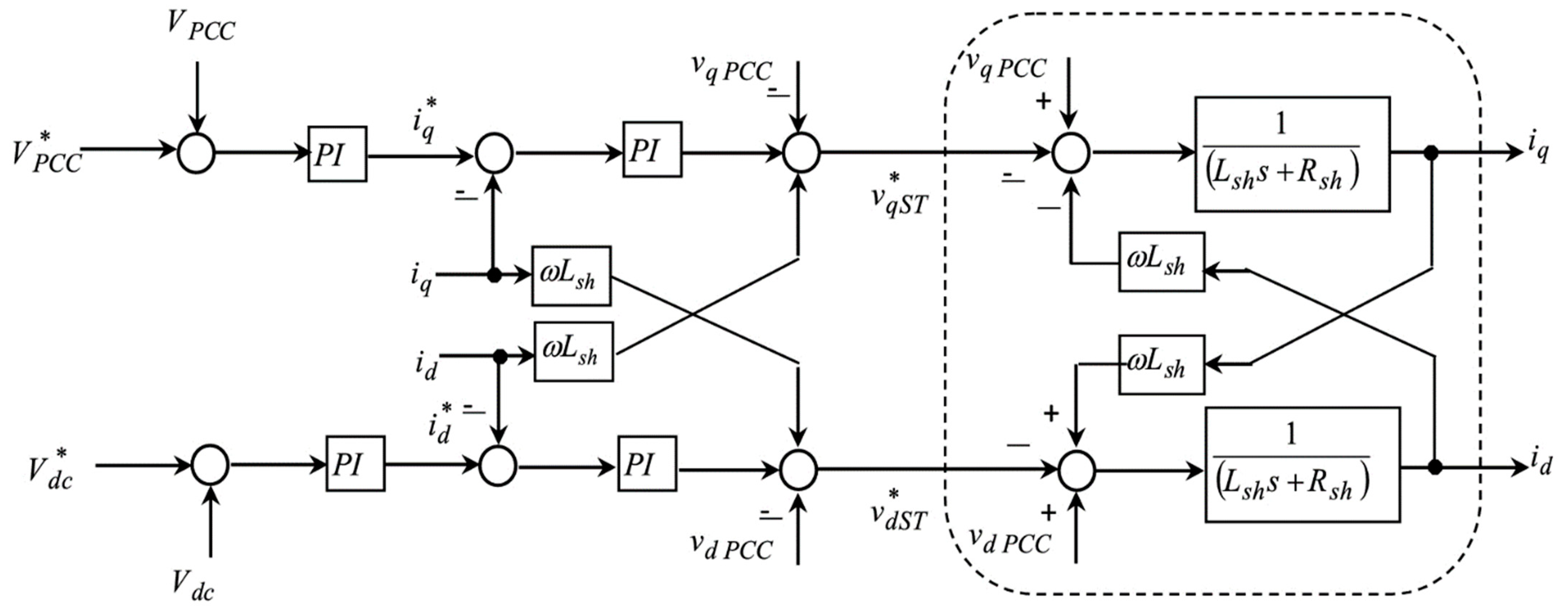
Modelling of DSTATCOM

The main feature of the DSTATCOM is controlling the operation of the exchange of power between MG and converter. When the magnitude of the output voltage of DSTATCOM is greater than that of the network, the DSTATCOM will inject reactive power into the network. In another case, if the convertor’s terminal voltage is lower than that of the network, the DSTATCOM will absorb reactive power from the network. In contrast, when the voltage magnitudes of the converter and the power network are identical, the DSTATCOM will operate in the equilibrium state, and the reactive power flowing between the power network and the converter will be zero.
The active and reactive power injected into the network by the DSTATCOM can be formulated as follows,
P ST = V PCC V ST sin δ x ST ,
Q ST = V PCC ( V PCC V ST cos δ ) x ST ,
where δ is the shift angle between the voltage at the point of common coupling VPCC and the STATCOM voltage V ST , x ST donates the reactance of the coupling transformer. The voltage generated by the DSTATCOM and V PCC are tuned (i.e., δ = zero). Accordingly, there is only reactive power transfer between the DSTATCOM and the network. The value of the reactive power flow, in this case, will be determined as follows,
Q ST = V PCC ( V PCC V ST ) x ST ,
The correspondent circuit of the DSTATCOM is shown in Figure 2. The resistance Rsh represents the active power losses in the winding of the coupling transformer and switches, whereas the inductance Lsh signifies the leakage in the coupling transformer.
According to the simplified equivalent circuit of the DSTATCOM, the currents and voltages will be presented in the Park reference frame as follows [42,43,44],
L sh d dt [ i q i d ] = [ R sh ω s L sh ω s L sh R sh ] [ i q i d ] + [ v qPCC v qST v dPCC v dST ] .
According to Equation (8), it is evident that the instantaneous voltages of the network and the voltage generated by D-STATCOM are not related to each other, but i d and i q are linked via the reactance of the coupling transformer [45]. The active and reactive currents have to be separated, then a control strategy for monitoring the desired voltage value will be demonstrated.
For DC bus side, the DC bus voltage is presented by:
V dc = 1 C i dc dt .
Then, the DC current will be calculated by:
i dc = m ( i q sin ( δ ) + i d cos ( δ ) ) .
Figure 3 shows the voltage and current vectors in a Park reference frame. The phase-shift angle δ and conversion ratio m will be derived from Figure 3. The ratio m will be calculated as follows:
m = v qST 2 + v dST 2 V dc ,
And the phase-shift angle will be:
δ = tg 1 ( v qST v dST ) ,
The derived block diagram in Figure 4 shows the control of the D-STATCOM using the conventional PI controller. The control system includes four control loops: two external loops for controlling the voltage at the point of common coupling and DC bus voltage; and the other two internal loops for controlling the power flow between the DSTATCOM and the network. As mentioned above, the currents in the control model that have been presented by Equation (19) are dependent.
According to the previous figure, a decoupling controller is made to discriminate between active and reactive powers. The main control system of D-STATCOM depends on PI controller, and its main objective is maintaining the constant voltage at the main coupling point (PCC). Keeping constant voltage for the load bus voltage is achieved through controlling the amplitude or/and shifting the output voltage of the D-STATCOM. The trial and error method based on system parameters is the most common method deployed to choose the PI controller parameters. The drawbacks of such a method are the large overshoots and the higher settling time that occurs under transient conditions. The optimization techniques can be deployed from this context to adapt the PI parameter gains to enhance dynamic performance despite system parameters [44,46]. In the proposed model, the conventional PI controller was utilized.

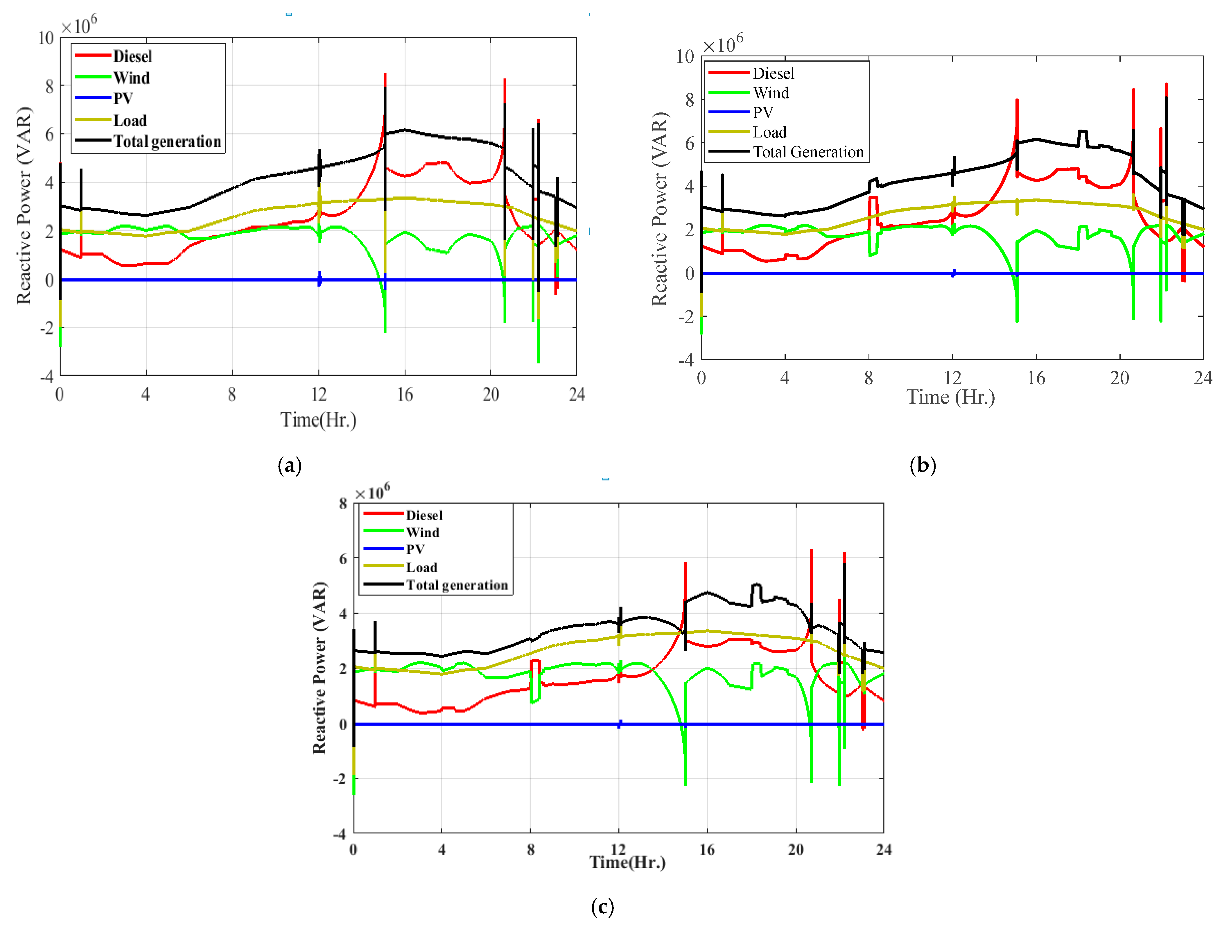
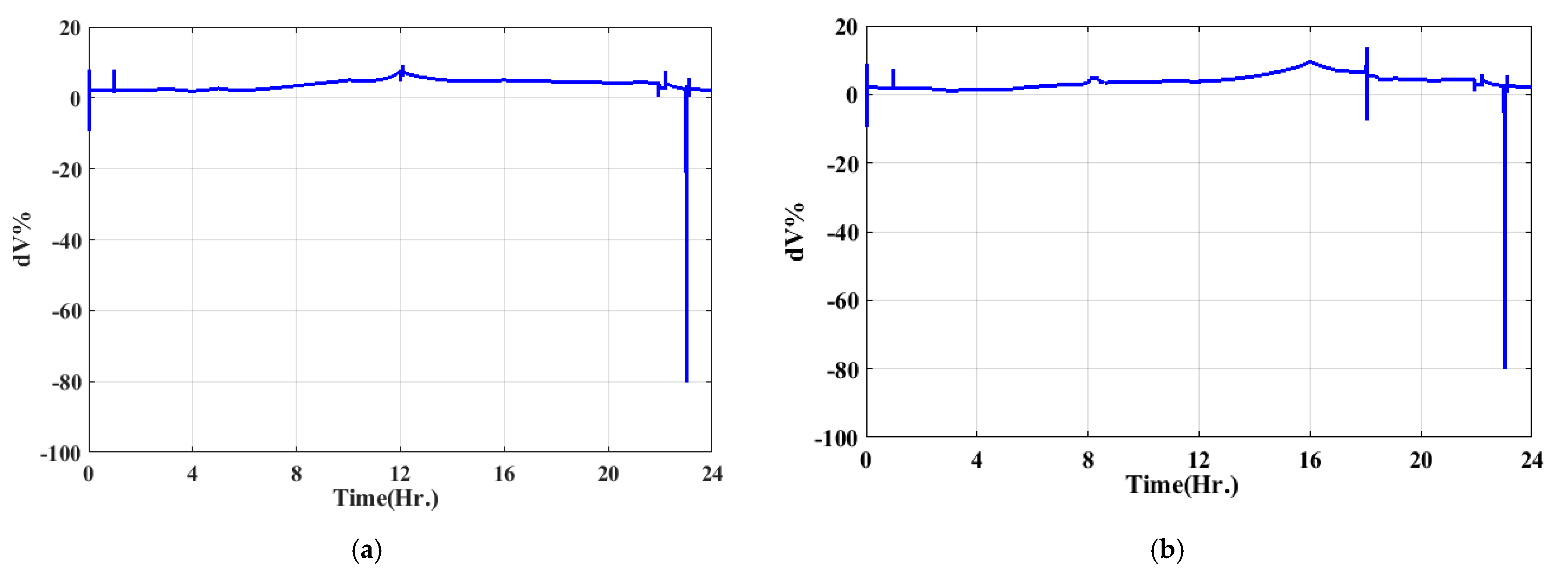
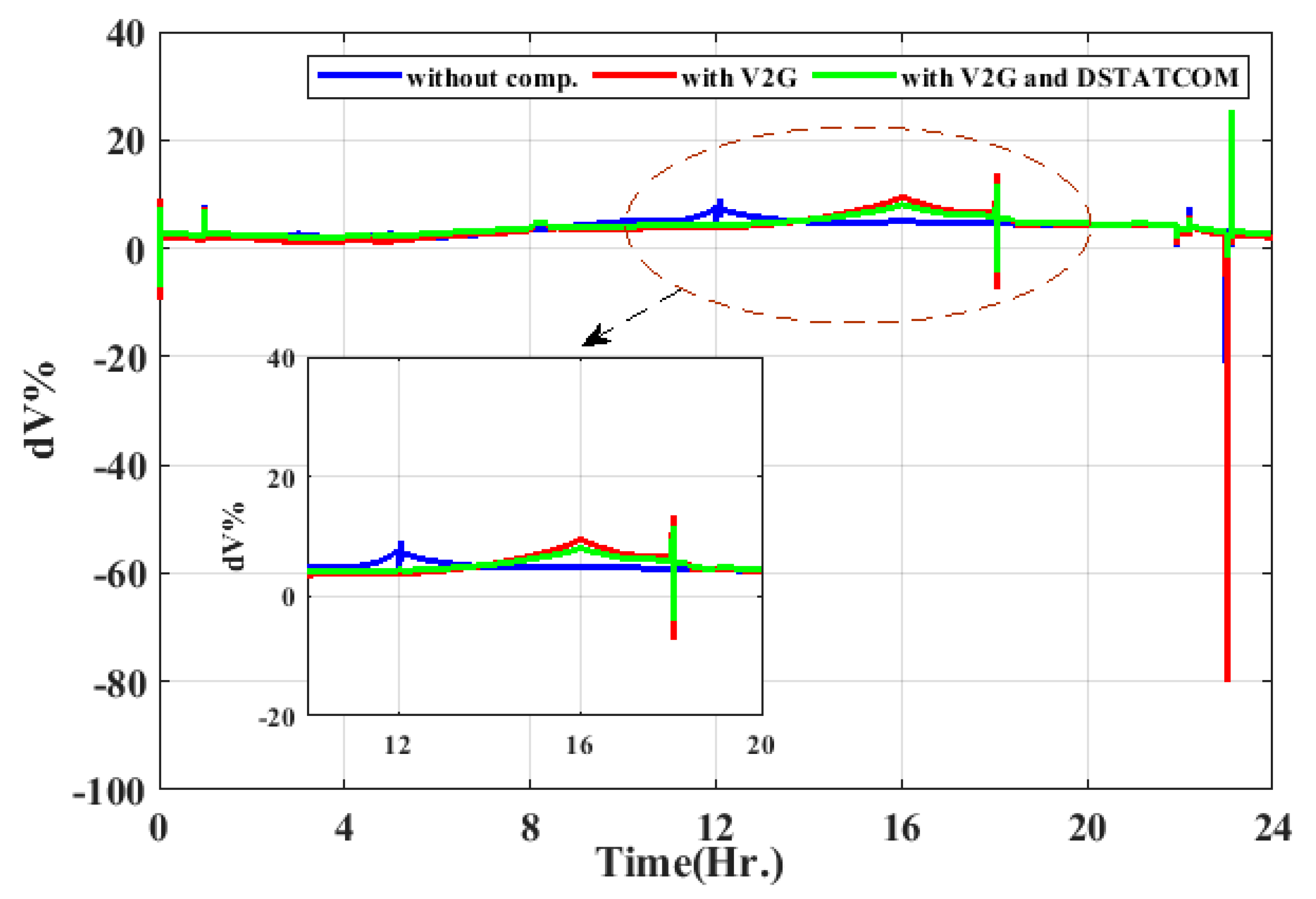
5. Results and Discussion

The Matlab/Simulink program was used to provide a simulation for the system under study. The simulation period lasted for a total of 24 h. The simulation model is based on the example provided in the MATLAB library [46,47]. The simulation model incorporates various generating units. It includes a 15 MW diesel generator, a PV power plant, a wind farm, an EV fleet, and a load. The model presents an off-grid energy system. The EV aggregator controls all the EVs for providing ancillary services to the power network during periods of need. The model is an isolated power system. The sun intensity if of a regular distribution nature, with the maximum intensity taking place at noon. The solar irradiance through the day is illustrated in Figure 5, where the PV system efficiency is 10% and the estimated area is 80 km2. The PV power plant is working under partial shading while the shading factor is equal to 0.7, and the period of shading is taken as 5 min. The output of the PV farm will change if the shading factor is changed, whereas the output of other generating units will not be affected. The output of the PV plant will have a dip at the time of the partial shading, as shown in Figure 5. The power produced from the PV farm drops to almost 70% when 30% of the PV array is shaded, and that is when the shading factor is 0.7. The wind speed changes intensely in the day and has multiple peaks and lows. The wind speed profile is shown in Figure 6. The residential load has a similar pattern to classic household usage. During the day, the energy utilization is modest and increases to peak in the evening. After that, it decreases during the night time. Figure 7 shows the load profile, which asserts the MG’s output power, which means the grid’s total generated power. This should also be the case, as the load consumption should equal the generation. The generated energy must be equivalent to the consumed energy. During the drop in the PV power output during early hours and nighttime or due to the shading effect of the PV arrays, the EV aggregator should provide regulatory power services to the microgrid and consequently maintain the system stability, which indicates the charging/discharging of EVs the entire duration. Still, the EVs integrated into the grid during the power fall periods would provide a deficit in generated power. Thus, the EV aggregator’s state of charge (SOC) should be the thing that deserves monitoring and studying.
The scenarios expected through the day usage can be described as follows:
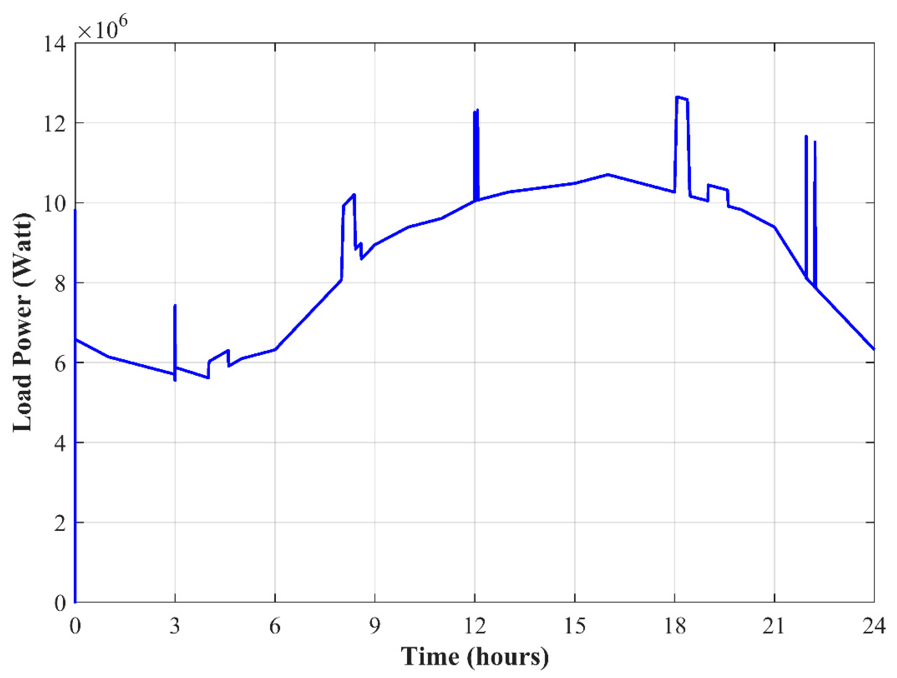
  • At the third hour, the asynchronous machine works.
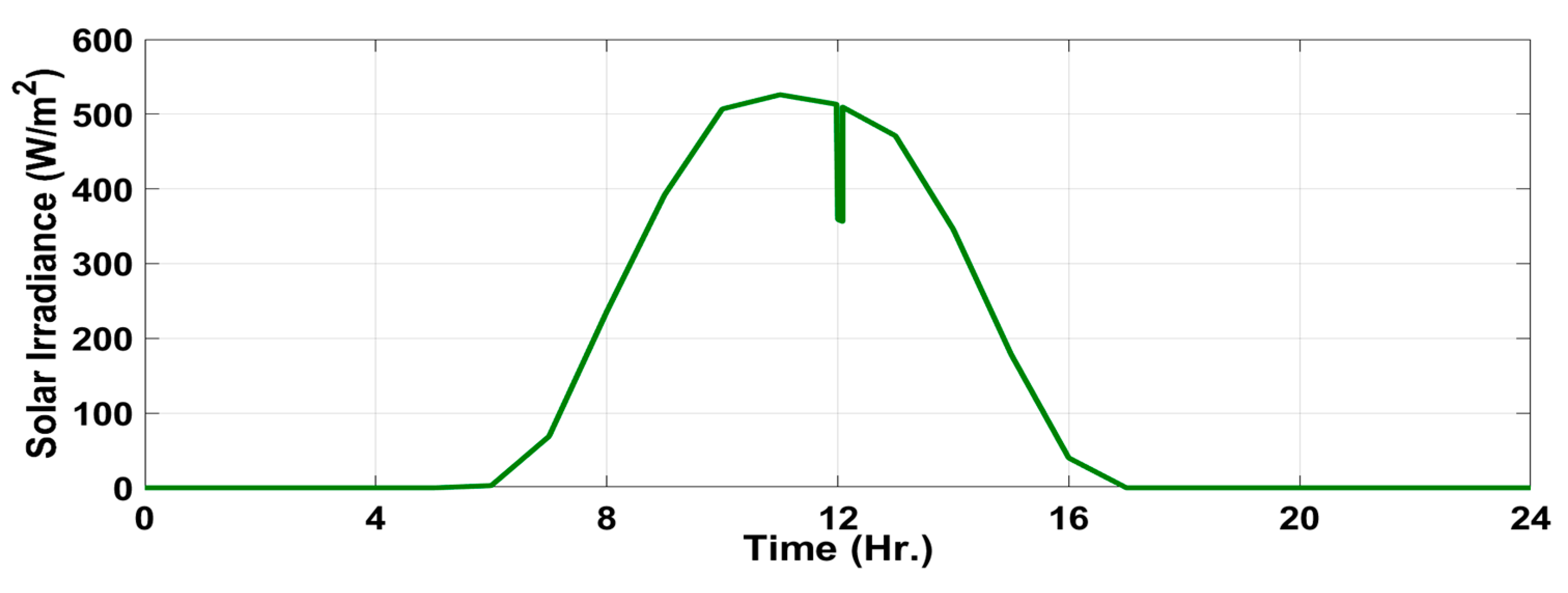
  • Solar power production decreases with partial shading during the midday.
  • At 22 h, a sudden trip occurs for the wind farm due to high wind speed.
The dynamic operation of the V2G is restricted either by charging the batteries or supplying power to the MG and can be concluded as follows:
  • People charging their cars during work “grid to vehicle (G2V) concept”.
  • People going to work without their own car “V2G”.
  • People not operating “vehicle to the grid—V2G”.
  • People working during the night “G2V”.
Figure 8 depicts the four possible SOCs for the aggregate model of EVs. The SOC lies between +ve 100% and −ve 100%. When the SOC is a negative value, the EVs are functioning in the V2G operating mode, whereas the positive values of SOC present G2V operation mode. The expected power of the aggregate model of the EVs is shown in Figure 9.
Figure 10 demonstrates the reactive power of both wind farm and solar PV, where a negative Q indicates that this kind of renewable energy source needs reactive power regulation. Hence DSTACTCOM is introduced to obtain enhanced performance. Figure 11 shows the possibly generated power from renewable energy sources and the DG. Figure 11a shows the system performance with the V2G and without using the DSTATCOMs. The DG plays a vital role in preserving the MG’s stability. The total generated power using the V2G concept with the four possible scenarios is illustrated in Figure 11b; the MGs indicated power spikes throughout the day. Figure 11c depicts the total system power with DSTATCOM and V2G compensation. Figure 12 shows the reactive power regulation for the system with the three proposed configurations. It is clear that the coordinated concept between V2G and DSTATCOM decreases the stress on the DG. As a matter of the stochastic nature of renewable energy resources, it works under a constant power factor and consumes reactive power. For reactive power regulation, using a combination set from DSTATCOM and V2G gives better performance.
Figure 13 indicates the load voltage and current, where little load current fluctuations are found with the V2G and DSTATCOM concepts. Figure 14 depicts the enhancement in the voltage stability of the system. Where the load voltage profile without any regulation devices is terrible, it is quite good with the V2G support, and it is better with DSTATCOM. The partial shading that occurs at midday increases voltage deviation. Moreover, tripping the wind farm from the MG at 22 h shows a large load voltage deviation. With the V2G concept, the deviation decreases but the voltage overshoots increase. In comparison, the DSTATCOM enhances the voltage stability and decreases the voltage overshoots, as illustrated in Figure 15.
The frequency response for the MG under study is illustrated in Figure 16. On the other hand, the different aspects of SOC for the EV lead to large variations in the frequency response, as shown in Figure 16b. In contrast, Figure 16c indicates that the system has a better frequency response with the insertion of DSTATCOM into the MG. Different parameters for the EV, like the voltage, current active power, and reactive power, are presented in Figure 17.

6. Conclusions

A new isolated MG structure is suggested in this study to diminish voltage and frequency instabilities and improve the system’s dynamic performance. Aside from the significance of EVs, DSTATCOM is another focus of this study. The stochastic nature of renewable energy sources embedded in MGs has led to importing more energy sources. The DG is used to support the performance of the MGs. This work takes into account EV and DSTATCOM for the effective utilization of energy generated from MG. The V2G concept of EV can provide ASs for MGs to decrease the fuel consumption of DGs. A proper load management system can help to make good use of the energy stored in the EVs during uncertain periods. The V2G concept supplies the MGs with the necessary energy; however, the load voltage overshoot increases. With the EVs implementation, the violation operation of the MGs that depend on renewable energy sources is larger. Implementing the DSTATCOM in MG enhances both load voltage and frequency; thus, the system stability is proven. With a combination set between DSATACOM and the electrical V2G configuration, the load current and voltage have lower fluctuations, and better physical performance is obtained. Finally, it can be said that the proposed configuration allows a high penetration ratio of green sources. It should be noted that there are limitations to the introduced configuration as the absence of intelligent controllers, which may allow for escalating up the penetration ratio of renewable energy resources with improving the system response. So, future work should include designing and analyzing the intelligent control-based strategies of MGs, such as considering a special objective function and/or unique control strategy to enhance the control system performance.

Author Contributions

Conceptualization, O.M.K., H.M.S. and A.A.Z.D.; methodology, O.M.K., A.A.Z.D. and M.M.M.; software, O.M.K. and A.A.Z.D.; validation, H.M.S., O.M.K. and A.A.Z.D.; formal analysis, H.M.S., A.S.A.-S. and A.A.Z.D.; investigation, O.M.K., A.S.A.-S., A.A.Z.D. and M.M.M.; resources, A.A.Z.D. and A.S.A.-S.; data curation, H.M.S., A.S.A.-S. and A.A.Z.D.; writing—original draft preparation, O.M.K., A.A.Z.D. and H.M.S.; writing—review and editing, M.M.M., A.S.A.-S. and A.A.Z.D.; visualization, H.M.S., A.S.A.-S. and A.A.Z.D.; supervision, A.A.Z.D. All authors have read and agreed to the published version of the manuscript.

Funding

This work is supported by ASPIRE-ViP project.

Data Availability Statement

Data available on request from the authors.

Conflicts of Interest

The authors declare no conflict of interest.

References

  1. Gui, E.M.; Diesendorf, M.; MacGill, I. Distributed energy infrastructure paradigm: Community microgrids in a new institutional economics context. Renew. Sustain. Energy Rev. 2017, 72, 1355–1365. [Google Scholar] [CrossRef]
  2. Mahmoud, M.M. Improved current control loops in wind side converter with the support of wild horse optimizer for enhancing the dynamic performance of PMSG-based wind generation system. Int. J. Model. Simul. 2022, 00, 1–15. [Google Scholar] [CrossRef]
  3. Ma, Y.J.; Zhai, M.Y. Day-Ahead prediction of microgrid electricity demand using a hybrid artificial intelligence model. Processes 2019, 7, 320. [Google Scholar] [CrossRef]
  4. Gamarra, C.; Guerrero, J.M. Computational optimization techniques applied to microgrids planning: A review. Renew. Sustain. Energy Rev. 2015, 48, 413–424. [Google Scholar] [CrossRef]
  5. Gui, E.M.; MacGill, I. Typology of future clean energy communities: An exploratory structure, opportunities, and challenges. Energy Res. Soc. Sci. 2018, 35, 94–107. [Google Scholar] [CrossRef]
  6. Mahmoud, M.M.; Atia, B.S.; Abdelaziz, A.Y.; Aldin, N.A.N. Dynamic Performance Assessment of PMSG and DFIG-Based WECS with the Support of Manta Ray Foraging Optimizer Considering MPPT, Pitch Control, and FRT Capability Issues. Processes 2022, 12, 2723. [Google Scholar] [CrossRef]
  7. Debouza, M.; Al-Durra, A.; EL-Fouly, T.H.M.; Zeineldin, H.H. Survey on microgrids with flexible boundaries: Strategies, applications, and future trends. Electr. Power Syst. Res. 2022, 205, 107765. [Google Scholar] [CrossRef]
  8. Perez-DeLaMora, D.A.; Quiroz-Ibarra, J.E.; Fernandez-Anaya, G.; Hernandez-Martinez, E.G. Roadmap on community-based microgrids deployment: An extensive review. Energy Rep. 2021, 7, 2883–2898. [Google Scholar] [CrossRef]
  9. Dawood, F.; Shafiullah, G.M.; Anda, M. Stand-alone microgrid with 100% renewable energy: A case study with hybrid solar pv-battery-hydrogen. Sustainability 2020, 12, 2047. [Google Scholar] [CrossRef]
  10. Marqusee, J.; Becker, W.; Ericson, S. Resilience and economics of microgrids with PV, battery storage, and networked diesel generators. Adv. Appl. Energy 2021, 3, 100049. [Google Scholar] [CrossRef]
  11. Aslam, S.; Khalid, A.; Javaid, N. Towards efficient energy management in smart grids considering microgrids with day-ahead energy forecasting. Electr. Power Syst. Res. 2020, 182, 106232. [Google Scholar] [CrossRef]
  12. Warneryd, M.; Håkansson, M.; Karltorp, K. Unpacking the complexity of community microgrids: A review of institutions’ roles for development of microgrids. Renew. Sustain. Energy Rev. 2020, 121, 109690. [Google Scholar] [CrossRef]
  13. Arias-Londoño, A.; Montoya, O.D.; Grisales-Noreña, L.F. A chronological literature review of electric vehicle interactions with power distribution systems. Energies 2020, 13, 3016. [Google Scholar] [CrossRef]
  14. Colmenar-Santos, A.; Muñoz-Gómez, A.M.; Rosales-Asensio, E.; López-Rey, Á. Electric vehicle charging strategy to support renewable energy sources in Europe 2050 low-carbon scenario. Energy 2019, 183, 61–74. [Google Scholar] [CrossRef]
  15. Wu, Y.; Wang, Z.; Huangfu, Y.; Ravey, A.; Chrenko, D.; Gao, F. Hierarchical Operation of Electric Vehicle Charging Station in Smart Grid Integration Applications—An Overview. Int. J. Electr. Power Energy Syst. 2022, 139, 108005. [Google Scholar] [CrossRef]
  16. Aliabadi, S.F.; Taher, S.A.; Shahidehpour, M. Smart deregulated grid frequency control in presence of renewable energy resources by EVs charging control. IEEE Trans. Smart Grid 2018, 9, 1073–1085. [Google Scholar] [CrossRef]
  17. Egbue, O.; Uko, C. Multi-agent approach to modeling and simulation of microgrid operation with vehicle-to-grid system. Electr. J. 2020, 33, 106714. [Google Scholar] [CrossRef]
  18. Huang, X.Q.; Wang, F.; Tan, Y.H.; Wang, R.; Shao, J.K.; Chen, C. Coordinated scheduling of electric vehicles and renewable generation considering vehicle-to-grid mode. Chin. J. Eng. Des. 2016, 23, 67–73. [Google Scholar] [CrossRef]
  19. Zecchino, A.; Prostejovsky, A.M.; Ziras, C.; Marinelli, M. Large-scale provision of frequency control via V2G: The Bornholm power system case. Electr. Power Syst. Res. 2019, 170, 25–34. [Google Scholar] [CrossRef]
  20. Kumar, Y.V.P.; Bhimasingu, R. Design of voltage and current controller parameters using small signal model-based pole-zero cancellation method for improved transient response in microgrids. SN Appl. Sci. 2021, 3, 836. [Google Scholar] [CrossRef]
  21. Mahdavian, A.; Ghadimi, A.A.; Bayat, M. Microgrid small-signal stability analysis considering dynamic load model. IET Renew. Power Gener. 2021, 15, 2799–2813. [Google Scholar] [CrossRef]
  22. Zahedmanesh, A.; Muttaqi, K.M.; Islam, M.R.; Zhao, Y. Consensus-based decision making approach for techno-economic operation of largescale battery energy storage in industrial microgrids. J. Energy Storage 2022, 46, 103917. [Google Scholar] [CrossRef]
  23. Hannan, M.A.; Tan, S.Y.; Al-Shetwi, A.Q.; Jern, K.P.; Begum, R.A. Optimized controller for renewable energy sources integration into microgrid: Functions, constraints and suggestions. J. Clean. Prod. 2020, 256, 120419. [Google Scholar] [CrossRef]
  24. Ouramdane, O.; Elbouchikhi, E.; Amirat, Y.; Gooya, E.S. Optimal sizing and energy management of microgrids with Vehicle-to-Grid technology: A critical review and future trends. Energies 2021, 14, 4166. [Google Scholar] [CrossRef]
  25. Sadeghi, M.; Mollahasani, S.; Erol-Kantarci, M. Power loss-aware transactive microgrid coalitions under uncertainty. Energies 2020, 13, 5782. [Google Scholar] [CrossRef]
  26. Wong, Y.C.C.; Lim, C.S.; Goh, H.H.; Cruden, A.; Rotaru, M.D.; Kong, X. An Optimal Secondary Multi-Bus Voltage and Reactive Power Sharing Control Based on Non-Iterative Decoupled Linearized Power Flow for Islanded Microgrids. IEEE Access 2021, 9, 105242–105254. [Google Scholar] [CrossRef]
  27. Khan, M.Z.; Mu, C.; Habib, S.; Hashmi, K.; Ahmed, E.M.; Alhosaini, W. An optimal control scheme for load bus voltage regulation and reactive power-sharing in an islanded microgrid. Energies 2021, 14, 6490. [Google Scholar] [CrossRef]
  28. Alhelou, H.H.; Siano, P.; Tipaldi, M.; Iervolino, R.; Mahfoud, F. Primary frequency response improvement in interconnected power systems using electric vehicle virtual power plants. World Electr. Veh. J. 2020, 11, 40. [Google Scholar] [CrossRef]
  29. Peng, F.Z. Flexible AC Transmission Systems (FACTS) and Resilient AC Distribution Systems (RACDS) in Smart Grid. Proc. IEEE 2017, 105, 2099–2115. [Google Scholar] [CrossRef]
  30. Mahmoud, M.M.; Esmail, Y.M.; Atia, B.S.; Kamel, O.M.; AboRas, K.M.; Bajaj, M.; Hussain Bukhari, S.S.; Mbadjoun Wapet, D.E. Voltage Quality Enhancement of Low-Voltage Smart Distribution System Using Robust and Optimized DVR Controllers: Application of the Harris Hawks Algorithm. Int. Trans. Electr. Energy Syst. 2022, 2022, 4242996. [Google Scholar] [CrossRef]
  31. Mahmoud, M.M.; Ratib, M.K.; Aly, M.M.; Abdel, A.M.M. Application of Whale Optimization Technique for Evaluating the Performance of Wind-Driven PMSG Under Harsh Operating Events. Process Integr. Optim. Sustain. 2022, 6, 447–470. [Google Scholar] [CrossRef]
  32. Marqusee, J.; Ericson, S.; Jenket, D. Impact of emergency diesel generator reliability on microgrids and building-tied systems. Appl. Energy 2021, 285, 116437. [Google Scholar] [CrossRef]
  33. Rezkallah, M.; Singh, S.; Chandra, A.; Singh, B.; Tremblay, M.; Saad, M.; Geng, H. Comprehensive Controller Implementation for Wind-PV-Diesel Based Standalone Microgrid. IEEE Trans. Ind. Appl. 2019, 55, 5416–5428. [Google Scholar] [CrossRef]
  34. Diab, A.A.Z.; Sultan, H.M.; Mohamed, I.S.; Oleg, N.K.; Do, T.D. Application of different optimization algorithms for optimal sizing of pv/wind/diesel/battery storage stand-alone hybrid microgrid. IEEE Access 2019, 7, 119223–119245. [Google Scholar] [CrossRef]
  35. Sahoo, B.; Routray, S.K.; Rout, P.K.; Alhaider, M.M. Power quality and stability assessment of hybrid microgrid and electric vehicle through a novel transformation technique. Sustain. Energy Technol. Assess. 2022, 51, 101927. [Google Scholar] [CrossRef]
  36. Diab, A.A.Z.; Sultan, H.M.; Kuznetsov, O.N. Optimal sizing of hybrid solar/wind/hydroelectric pumped storage energy system in Egypt based on different meta-heuristic techniques. Environ. Sci. Pollut. Res. 2020, 27, 32318–32340. [Google Scholar] [CrossRef]
  37. Rodrigues, Y.R.; de Souza, A.C.Z.; Ribeiro, P.F. An inclusive methodology for Plug-in electrical vehicle operation with G2V and V2G in smart microgrid environments. Int. J. Electr. Power Energy Syst. 2018, 102, 312–323. [Google Scholar] [CrossRef]
  38. Meng, L.; Sanseverino, E.R.; Luna, A.; Dragicevic, T.; Vasquez, J.C.; Guerrero, J.M. Microgrid supervisory controllers and energy management systems: A literature review. Renew. Sustain. Energy Rev. 2016, 60, 1263–1273. [Google Scholar] [CrossRef]
  39. Shuai, Z.; Sun, Y.; Shen, Z.J.; Tian, W.; Tu, C.; Li, Y.; Yin, X. Microgrid stability: Classification and a review. Renew. Sustain. Energy Rev. 2016, 58, 167–179. [Google Scholar] [CrossRef]
  40. El Zoghby, H.M.; Ramadan, H.S. Isolated microgrid stability reinforcement using optimally controlled STATCOM. Sustain. Energy Technol. Assess. 2022, 50, 101883. [Google Scholar] [CrossRef]
  41. Hussain, S.M.S.; Aftab, M.A.; Ustun, T.S. Performance analysis of iec 61850 messages in lte communication for reactive power management in microgrids. Energies 2020, 13, 6011. [Google Scholar] [CrossRef]
  42. Li, X.; Li, H.; Li, S.; Jiang, Z.; Ma, X. Review on Reactive Power and Voltage Optimization of Active Distribution Network with Renewable Distributed Generation and Time-Varying Loads. Math. Probl. Eng. 2021, 2021, 1196369. [Google Scholar] [CrossRef]
  43. Mengi, O.O. A five-level H-Bridge STATCOM for an off-grid PV solar farm under two controllers PI and PIλ-MPC hybrid. Int. J. Photoenergy 2018, 2018, 4030214. [Google Scholar] [CrossRef]
  44. Movahedi, A.; Niasar, A.H.; Gharehpetian, G.B. Designing SSSC, TCSC, and STATCOM controllers using AVURPSO, GSA, and GA for transient stability improvement of a multi-machine power system with PV and wind farms. Int. J. Electr. Power Energy Syst. 2019, 106, 455–466. [Google Scholar] [CrossRef]
  45. Tennakoon, S.B.; Scheidecker, D. Multi-level converters for static var compensation. IEE Colloq. 1997, 4, 91. [Google Scholar] [CrossRef]
  46. Chola, R.; Singh, S.B. A Case Study on 24-h Simulation of V2G System. Lect. Notes Electr. Eng. 2021, 667, 131–140. [Google Scholar] [CrossRef]
  47. Rehman, U.U.; Riaz, M. Vehicle to grid system for load and frequency management in smart grid. In Proceedings of the ICOSST 2017—2017 International Conference on Open Source Systems and Technologies, Lahore, Pakistan, 18–20 December 2017; Volume 2018, pp. 73–78. [Google Scholar] [CrossRef]
Figure 1. MG major components and configuration.
Energies 16 01577 g001
Figure 2. Equivalent circuit of DSTATCOM.
Energies 16 01577 g002
Figure 3. Vector diagram of D-STATCOM voltages and currents.
Energies 16 01577 g003
Figure 4. Block diagram for the D-STATCOM control by conventional PI controller.
Energies 16 01577 g004
Figure 5. Solar irradiance of the PV system.
Energies 16 01577 g005
Figure 6. Wind speed profile.
Energies 16 01577 g006
Figure 7. Load profile.
Energies 16 01577 g007
Figure 8. The state of charge of EVs: (a) SOC of profile1; (b) SOC of profile2; (c) SOC of profile3; and (d) SOC of profile4.
Energies 16 01577 g008aEnergies 16 01577 g008b
Figure 9. Active and reactive power of EVs.
Energies 16 01577 g009
Figure 10. Generated reactive power: (a) Wind farm reactive power and (b) PV reactive power.
Energies 16 01577 g010
Figure 11. Total apparent power: (a) without any compensations; (b) with V2G compensations; (c) and with DSTATCOM and V2G compensations.
Energies 16 01577 g011
Figure 12. Total reactive power (a) without any compensations; (b) with V2G compensations; (c) and with DSTATCOM and V2G compensations.
Energies 16 01577 g012
Figure 13. Total Load Voltage and Current; (a) without any compensations; (b) with V2G compensations; and (c) with DSTATCOM and V2G compensations.
Energies 16 01577 g013
Figure 14. Load Voltage deviation; (a) without any compensations, (b) with V2G compensations, (c) and with DSTATCOM and V2G compensations.
Energies 16 01577 g014aEnergies 16 01577 g014b
Figure 15. Load Voltage deviation for the three case studies.
Energies 16 01577 g015
Figure 16. Frequency response for the MG; (a) without any compensations, (b) with V2G compensations, and (c) with DSTATCOM and V2G compensations.
Energies 16 01577 g016
Figure 17. Parameters of EV: (a) voltage, (b) current, (c) active power, and (d) reactive power.
Energies 16 01577 g017aEnergies 16 01577 g017b
Table 1. Main characteristic parameters of EV.
ParametersValue
Mass (m)1845 (kg)
Rolling resistance Coefficient (f)0.025
Coefficient of air resistance (C)0.36
Windward area (A)2.56 (m2)
Correction coefficient of the rotation mass (δ)1.03
Transmission system efficiency (nt)0.9
Gravity acceleration (g)9.8 (m/s2)
Road angle (α)0
Disclaimer/Publisher’s Note: The statements, opinions and data contained in all publications are solely those of the individual author(s) and contributor(s) and not of MDPI and/or the editor(s). MDPI and/or the editor(s) disclaim responsibility for any injury to people or property resulting from any ideas, methods, instructions or products referred to in the content.

