Article

A Comparative Thermal and Economic Investigation of Similar Shell & Tube and Plate Heat Exchangers with Low Concentration Ag-H2O Nanofluid

by
Seyed Hadi Pourhoseini
1,
Mojtaba Baghban
1 and
Maryam Ghodrat
2,*
1
Department of Mechanical Engineering, Faculty of Engineering, University of Gonabad, Gonabad 9691957678, Iran
2
School of Engineering and Information Technology, UNSW Canberra, Canberra, ACT 2612, Australia
*
Author to whom correspondence should be addressed.
Energies 2023, 16(4), 1854; https://doi.org/10.3390/en16041854
Submission received: 19 January 2023 / Revised: 6 February 2023 / Accepted: 10 February 2023 / Published: 13 February 2023

Abstract

:
Plate Heat Exchanger (PHE) and Shell and Tube Heat Exchanger (STHE) with identical heat transfer areas and material characteristics are proposed and a comparative thermal and economic comparative analysis is carried out on both exchangers. Ag-water nanofluid is used at low concentrations (0, 2.5, 5, 10 mg/L), flow rates (2, 5, and 8 L/min), and inlet temperatures (36, 46, and 56 °C) as hot flow and the heat transfer coefficient (U), electrical power consumption of the pump, and costs per unit of average U value are considered as the calculated parameters for each heat exchanger in co-current and counter-current flows. The results revealed that PHE generates a higher U value compared to the STHE under different Ag-water nanofluid concentrations. This is due to the existence of grooves on the plates of PHE which generates turbulent flow. The impact of nanofluid concentration on U is negligible for lower concentrations in both PHE and STHE. It is also found that the nanofluid flow rate has the highest impact on the U value, just like conventional fluid. Besides, even though counter-current flow increases the U values for both PHE and STHE, the flow pattern has a higher impact on the U value of PHE than that of STHE. For both PHE and STHE, increasing the nanofluid flow rate enhances the amount of U. However, the effect of flow rate on the U value of PHE is greater than that of the STHE. It is also shown that throughout the entire experimental temperature domain, PHE has had higher performance than STHE, and as the fluid temperature increased from 36 to 56 °C, there was a slight increase in the overall heat transfer of both PHE and STHE. Furthermore, for the same flow rate, both PHE and STHE had almost the same pump power consumption, and increasing the nanofluid flow rate from 2 L/min to 8 L/min promoted the electrical power consumption of the pump. Finally, we found that the costs per unit of heat transfer coefficient for PHE are significantly lower than STHE. The presented results also indicated that using a vortex generator at the inlet of STHE tubes, to form turbulent flow, increases the U values of STHE for both co-current and counter-current flows but these U values are lower than the corresponding U values of PHE. Small plates gap in PHE structure cause higher fluid flow velocities and create a chain-like structure of nanoparticles (NPs) between PHE’s plates (especially at higher nanofluids concentrations).

1. Introduction

Heat exchangers are among the most well-known and widespread heat transfer devices for the transfer of heat between two fluid flows in cooling and heating systems [1]. These fluids may be a gas, liquid, or a combination of both, and the fluids may be mixed together or separated by a solid wall. Also, the configuration of heat exchangers must be provided the maximum heat transfer area to increase the thermal efficiency of the heat exchanger while minimizing the pressure drop.
Shell and tube heat exchangers (STHE) and plate heat exchangers (PHE) are the most common and popular types of heat exchangers [2]. An STHE has several tubes installed within a cylindrical container known as a ‘shell’. Each tube passes through a series of baffles and tube sheets. High-pressure fluid flows into the tube side medium while low-pressure fluid flows into the shell side. APHEconsists of a series of metalplates known as hot plates and cold plates fluids flow over these plates and the transferheatprocess between two fluids is done through these plates. The main advantage of this type of converter is to provide a high heat transfer surface in a small volume. PHEs are now widely used in domestic hot water packages and industrial applications. Smaller versions of PHEs tend to be brazed, whereas larger commercial versions usegasketsbetween the plates.
There are several investigations about the enhancement of heat transfer characteristics of STHEs and PHEs. For example, for the aim of heat transfer improvement of STHEs, Wang et al. [3] used sealers on the shell side to fill the slots between theshell and baffle plates. They observed that this method effectively reduces the short-circuit flow in the shell side. Also, the heat transfer results of the modified STHE revealed an increase in the heat transfer coefficient of shell-side, the overall heat transfer coefficient, and exergy efficiency as much as 18.2–25.5%, 15.6–19.7% and 12.9–14.1%, respectively. Also, they observed that the installation of sealers increases the pressure drop by 44.6–48.8%. However, they stated that the increase in pumping cost resulting from increased pressure drop is negligible compared to the improvement of heat transfer. Finally, they mentioned that the installation of sealers on the shell side intensified the heat transfer efficiency of STHE. Hosseini et al. [4] experimentally studied the impact of the outer surface pattern of tubes including smooth, corrugated, and with micro-fins on the pressure drop and heat transfer coefficient of an STHE. Also, the obtained experimental data were compared with the theoretical data available. The findings revealed that the use of micro-finned tubes significantly enhances the thermal performance of STHE, especially at higher Reynolds numbers. However, at a low Reynolds number (Re < 400), corrugated and micro-fin tubes showed a reduction in performance. In another similar work, Amini et al. [5] investigated the impact of using segmented and helical tube fins on the heat transfer performance (HTP) of an STHE. The study was a numerical base using FLUENT for different conditions. The simulations showed using segmented fins and helical fins increase HTP by as much as 6% and 9.5%, respectively. Also, they reported that the simultaneousness of helical fins with larger height and smaller pitch and low surface roughness prominently increases the efficiency of the STHE. Zhang et al. [6] have done a study on the techniques of enhancement heat transfer in plate heat exchangers. Geometrical parameters, passive surface, and diverse heat transfer enhancement techniques were investigated and compared. This review indicated that for the chevron-type PHE, the chevron angle has the greatest impact on the heat transfer characteristics by changing the flow structures. Also, they mentioned that these techniques are commonly effective at low Reynolds numbers. Gut et al. [7] expanded a model in the algorithm for the steady-state simulation of gasketed plate heat exchangers (GPHE) with generalized configurations. The number of channels and passes at each side, feed connection locations, fluid locations, and type of channel flow were the configuration parameters. The main aim of this work was to find a more flexible algorithm for the simulation and comparison of various configurations of PHEs. Luan et al. [8] proposed a new design for the corrugated PHE. In the proposed design, compound corrugated plates were used. The performance characteristics of the new proposed design were investigated both experimentally and numerically. The findings showed that, although the new proposed design decreases the resistance to flow compared to the ordinary chevron type up to 50% the heat transfer rate was reduced by about 25%.
Nanoparticles are small-scale metallic or non-metallic particles, which have a high surface area/volume ratio and unique properties that make them a suitable choice for a variety of applications [9,10]. In this way, nanoparticles have made essential developments in various fields such as medicine [11,12,13,14,15,16], chemical sensors [17,18,19,20,21], bio and electrical engineering [22,23,24], semiconductors [25,26,27,28], electronics and energy applications [29,30,31,32]. Since nanoparticles (NPs) have unique properties compared to fluids, using them as additives can enhance the convection and thermal performance of heat exchangers [33,34,35,36,37,38]. Atashafrooz [39] numerically investigated the effects of Ag-water nanofluid on thermal and hydrodynamic behaviors of three-dimensional separated step flow. The numerical results showed that the effect of nanofluid concentration on temperature is significantly greater than the velocity distribution. Furthermore, an increase in nanoparticle concentration raises the friction coefficient and mean bulk temperature. In another numerical study, Harish and Sivakumar [40] used a two-phase mixture model to investigate the flow and heat transfer characteristics of nanofluids inside a cubical enclosure. Silver (Ag), Copper (Cu) and Aluminum oxide (Al2O3) were the selected nanoparticles. The results showed that the random Brownian motion of nanoparticles increases thermal convection and enhances the rate of energy exchange between the fluid and particle phases. Also, they observed that Ag nanoparticles are the most effective nanoparticles additive. Farajollahi et al. [41] investigated the impacts of TiO2-H2O and Al2O3-H2O nanofluids (NFs) flow in STHE on thermal properties. They observed that both nanoparticles (NPs) have a great effect on HTP. Furthermore, the γ-Al2O3-H2O shows more improvement than the TiO2-H2O nanofluid. Elias et al. [42] perused the impact of NPs shapes on the thermal and entropy generation of an STHE. They reported that cylindrical shape nanoparticles have the best U value compared to other forms. Bahiraei et al. [43] investigated the effects of Boehmite NPs shapes on the thermal-hydraulic characteristics of an STHE. They concluded that platelet-shaped NPs have the highest U value, and Os-shaped nanoparticles gain minor pressure loss in the STHE. Anitha et al. [44] studied the HTP of alumina-copper/water hybrid NF in an STHE. They revealed that when they used a hybrid nanofluid in the STHE, nanoparticle concentration and proportion had the most impact on the HTP. Furthermore, hybrid nanofluid significantly increased the effectiveness of the heat exchanger. In another work, Bahiraei and Monavari [45] investigated the impacts of NPs shapes on the performance of a mini STHE with fin and without fin in their structure. They observed increasing the Reynolds number of nanofluid raised U value, pressure drop (PD), and effectiveness of the STHE. Furthermore, they showed that the existence of a fin improved the heat transfer efficiency of the STHE. Huang et al. [46] investigated HTP and PD of hybrid NFs in plate heat exchangers (PHE). Hybrid NF was a mixture of MWCNT-H2O and Al2O3-H2O NFs. The results showed that hybrid NFs give a slightly larger U value than Al2O3-H2O NFs at the same flow rates. In addition, compared to the Al2O3-H2O NFs, hybrid NFs in PHE decreased PD. Taghizadeh-Tabari et al. [47] tested TiO2-H2O NFs in the PHE of milk industries. They observed that TiO2-H2O NFs at all concentrations raise both HTP and PD. Furthermore, the performance indexes (the ratio of convection enhancement to the PD), which simultaneously considered both heat transfer rate and pressure drop, increased. In a similar study, Barzegarian et al. [48] investigated the impacts of TiO2-H2O NFs in a BPHE (brazed PHE) on HTP and PD properties. The NF concentrations in this study were 0.3%, 0.8%, and 1.5% (by weight). The results showed that while NF enhanced the convective heat transfer coefficient (h) and U value, its impact on PD was negligible. The maximum enhancement of h and U were 23.7% and 8.5%, respectively. Bhattad et al. [49] perused the HTP of PHE using hybrid NFs. They produced hybrid NFs by mixing Al2O3 NPs with TiO2 NPs in different ratios (5:0, 4:1, 3:2, 2:3, 1:4, and 0:5). The maximum enhancement of heat transfer rate belonged to Al2O3 (5:0) hybrid NF as much as 4.5% and the maximum increase in pump work was about 0.013% for TiO2 (0:5) hybrid NF. Hajabdollahi et al. [50] studied the effects of NPs shape on thermal characteristics and the annual cost of a GPHE. In the study, they used alumina and boehmite NPs with different shapes including blade, platelet, cylinder, and brick. This investigation showed that from a thermo-economic improvement point of view, cylinder shape is the most optimal shape for NPs and platelet, brick, and blade shapes were in the next ranks. Furthermore, they reported that using both alumina and boehmite NF as working fluid in PHE decreases the required heat exchanger volume. Gürbüz et al. [51] investigated utilizing NF, as a widely used method forthe enhancement of the thermal properties of PHEs. In their case study, they used hybrid-type NF consisting of the same amount of alumina and copper oxide NPs. They used the hybrid NF in PHEs with different plates (8, 12, and 16 plates) and observed that the use of hybrid-type NF instead of single-type NF improves the HTP of PHE. Also, the results demonstrated that an increase in theHE plate number leads to more increasein HTP.Sözen et al. [52] prepared NF including 2% (wt/wt) kaolin and 0.2% (wt/wt) Triton X-100 surfactant and used it as a working fluid in a PHE. Temperature and mass flow rate of NF varied in the experiments and the results showed an increase in mean U value of as much as 9.3% compared to the deionized water.
A detailed survey of the existing literature reveals that by far most studies only investigated the effects of nanofluids on the HTP of PHE or STHE. However, there is no coherent thermal and economic comparative study on the application of nanoparticles in PHE and STHE as the most common and popular types of heat exchangers from both a heat transfer and economic characteristics point of view. Consequently, in this work, we determined a PHE and STHE with the same heat transfer area and material characteristics. Then we carried out a comparative investigation on the effect of different low concentrations, flow rates, flow regimes, and fluid temperatures of Ag-H2O nanofluids on the overall heat transfer coefficient (U) and the costs related to U value (costs per unit of U value) for both PHE and STHE. It is worth mentioning that the reason behind the use of Ag nanoparticles is that they are among the most well-known metal nanoparticles which play a special role due to their unique optical, electrical, and thermal properties [53,54]. Also, they have higher thermal conductivity (429 W/m.K at 300 K) than very nanofluids such as hybrid nanofluids which are mentioned above and consequently they will show a high limit of the effect of using nanofluids.

2. Materials, Experimental Setup, and Procedure

Silver-Water nanofluid in the concentration of 100 mg/L was produced by the chemical reduction method explained in the previous work [55]. In this method, AgNO3 (17.0 mg) was dissolved in 100 mL of water in a 250 mL tri-neck flask. The solution was heated to boiling point with a hemisphere-heating mantle under vigorous magnetic stirring. After boiling for 2 min, an aqueous solution of sodium citrate (35 mM, 10 mL) was rapidly added to the flask. The solution gradually turned yellow within a few minutes, indicating the formation of Ag nanoparticles. The solution was kept boiling for an additional 6 min. After that, the heating mantle was removed, and the solution was allowed to cool down so that we obtained synthesized silver-water nanofluid of a concentration of 100 mg/L. Figure 1 illustrates the AFM image of Ag NPs. The average diameter of the Ag NPs was 16.2 nm. The diluted concentrations obtained from synthesized silver-water nanofluid were 2.5, 5, and 10 mg/L. Nanofluids were poured into an insulated tank installed on the test setup and preheated to reach the specified temperature with an electric immersion heater of 3 kW. Figure 2 shows a schematic of the test setup. Its main components are:
1: Two rotameters to adjust the flow rates of the hot and cold streams (Flow Range: 0.8–8 L/min, accuracy = ±2%).
2: Four pt100 temperature sensors with digital display to measure the inlet and outlet temperatures of hot and cold fluid flows (Temperature range: −50–400 °C, accuracy = ±1%).
3: A centrifugal pump (stainless steel, nominal power = 0.37 KW) to circulate nanofluid between the tank and heat exchanger.
4: Voltmeter and ammeter used to measure the power consumption of the pump (pump work).
5: Heat exchanger (PHE/STHE).
Figure 3 shows the geometrical configuration of STHE (left) and PHE (right). STHE is a single type and consists of tubes, shells, baffles, and hot and cold flow inlets and outlets. Also, PHE has grooved plates in which hot and cold fluids flow over them. Table 1 and Table 2 show the detailed specification of the PHE and STHE including materials and dimensions, respectively.
After installation of the heat exchanger on the test setup, silver-water nanofluid as the hot stream and pure water as the cold stream were flowing, and the data including inlet and outlet temperatures, flow rates, voltage, and energy requirement of the pump (volts and amps) were recorded in steady condition. The volume flow rates were 2, 5, and 8 L/min for the silver-water nanofluid and the volume flow rate of the cold fluid was adjusted at 3 L/min for all experiments. Also, the inlet temperatures of nanofluids were 36, 46, and 56 °C. Finally, to make sure of the accuracy of the results, the uncertainty analysis was done according to the repeatability of measurements, and the accuracy of the tools.

3. Data Analysis

U value was derived from the following relation:
U = Q A Δ T LMTD
where A is the total surface area of heat exchangers (0.21 m2), and ΔTLMTD is called the logarithmic mean temperature difference and is formulated as follows:
Δ T L M T D = T h , i n   T c , o u t   T h , o u t   T c , i n   l n   T h , i n   T c , o u t   T h , o u t   T c , i n                     C o u n t e r c u r r e n t        
Δ T L M T D = T h , i n   T c , i n   T h , o u t   T c , o u t   l n   T h , i n   T c , i n   T h , o u t   T c , o u t                                     C o c u r r e n t      
where Th,in and Th,out are the steady temperatures of the hot stream at the inlet and outlet of the heat exchanger (HE), and Tc,in and Tc,out are the inlet and outlet temperatures of cold fluid flow, respectively. Q is the average heat transfer rate in the HE and can be determined by the following equations:
Q = Q h + Q c 2
The heat transfer rates of hot flow Qh and cold flow Qc were calculated from the following equations:
Q h = m ˙ h C p , h T h , i n   T h , o u t  
Q c = m ˙ c C p , c T c , o u t   T c , i n          
where m ˙ h and m ˙ c are the mass flow rates of hot and cold fluid flows, and Cp,h and Cp,c are their specific heat capacities, respectively.

4. Results and Discussion

In Figure 4, we compare the impact of nanofluid concentration on the U value for PHE and STHE at co-current and counter-current flows. The nanofluid fluid rate and temperature are 8 L/min and 55 °C, respectively. It shows that PHE creates a higher U value than STHE at different concentrations. However, when the nanofluid concentration is low, nanofluid concentration changes do not significant difference in the U value compared to pure water (Nanofluid concentration = 0). Finally, although counter-current flow increases the amount of U for both PHE and STHE, the flow pattern has a higher impact on the U value of PHE than the STHE.
Figure 5 illustrates the impact of nanofluid flow rate on U values of PHE and STHE at a nanofluid concentration of 10 mg/L and nanofluid temperatures of 55 °C. It reveals that for both PHE and STHE, an increase in nanofluid flow rate enhances the amount of the U. However, the effect of flow rate on the U value of PHE is greater than that of STHE. It can be explained by the hot flow regime and physical structure of PHE and STHE. Based on Table 2, the internal diameter of tubes in the STHE, in which nanofluid as a hot stream flows in it, is 4 mm. Furthermore, the STHE has 30 tubes, and consequently, the Reynolds number of the hot stream for maximum flow rate 8 L/min is about 1415, which is lower than the critical Reynolds number (about 2300) for the transition from laminar into turbulent. Therefore, for all of the flow rates in the experiment, the flow regime for nanofluid as a hot stream in the STHE is laminar. However, the existence of grooves on the plates of PHE raises the probability of turbulent flow. The turbulent regime raises the heat transfer coefficient and, consequently U value. In addition, in contrast to the case of STHE, in the case of PHE, an increase in flow rate decreases the slope of the “U-flow rate” diagram. As a result, when the flow rate increases, the impact of the flow rate on the U value decreases, and we can say that there is a critical flow rate for amplification of the U value of a PHE, and the amount of this critical flow rate is smaller than the STHE. After this critical flow rate, a saturation condition occurs.
Figure 6 compares the performance of PHE and STHE at different temperatures of the Ag-H2O nanofluid. The nanofluid flow rate and concentration are 8 L/min and 10 mg/L, respectively. We reveal that in the whole temperature domain, PHE has higher performance than STHE. As well as, when the fluid temperature increases from 36 to 56 °C, there is a slight increase in the overall heat transfer of both PHE and STHE. Furthermore, for counter-current flow, the effect of nanofluid temperature on the enhancement of U is more remarkable than the co-current flow. Finally, the comparison of the results from Figure 4, Figure 5 and Figure 6 declare that when the nanofluid concentration is below as seen for a conventional fluid, among the characteristics of concentration, inlet temperature, and volume flow rate, the nanofluid flow rate has the highest impact on the U value.
Figure 7 shows the effects of NF concentration and flow rate on the electrical power consumption of the pump for PHE and STHE. The nanofluid temperature is 55 °C. Since the nanofluid concentration is low, it has a negligible impact on power consumption. The reason behind this is a lower concentration of nanofluid has a negligible effect on the increase of the fluid viscosity, and below nanofluid concentration does not raise the power consumption significantly. In addition, Figure 7 released that for the same flow rate, both PHE and STHE have almost the same pump power consumption, and increasing the nanofluid flow rate from 2 L/min to 8 L/min promotes the electrical power consumption of the pump.
In Figure 8, the heat transfer costs of PHE and STHE are compared for co-current and counter-current flows. Economic comparison is done based on the cost of construction and installation of each heat exchanger. It is worth mentioning that, based on the results in Figure 7, for the same flow rate, both PHE and STHE have almost the same pump power consumption. Consequently, the electricity cost is almost the same for both heat exchangers and therefore it is not included in the economic comparison of the heat exchangers. Also, the cost of nanofluid synthesis and preparation (32 $) was the same for both heat exchangers and therefore it also is not included in the economic comparison of the heat exchangers. STHE and PHE construction and installation costs were 470 $ and 300 $, respectively. Therefore, considering the U values of heat exchangers corresponded to the maximum nanofluid flow rate (8 L/min) and maximum nanofluid temperature (55 °C) which are presented in Figure 4, the costs per unit of U value for PHE and STHE are calculated. It reveals that the costs per unit of U value for a PHE are significantly smaller than that of STHE. In addition, compared with the counter-current flow, the co-current regime raises heat transfer costs. Therefore, from an economic point of view and in conventional applications, it is more affordable to use PHE instead of STHE. Of course, it is worth mentioning that for specific applications like corrosive liquids or very high pressures, using STHE is more suitable than PHE because of easy maintenance, repairing, and cleaning.
As mentioned in Figure 5, for all the flow rates in the experiment, the flow regime for nanofluid as a hot stream in the STHE is laminar. However, the existence of grooves on the plates of PHE makes turbulent flow and a turbulent regime raise the heat transfer coefficient and, consequently U value.Now we want to find out the change in a flow regime from laminar to turbulent in STHE and how influences U value. For this purpose, using vortex generator is used in the inlet of STHE tubes to make the turbulent flow and the experiments were repeated. In Figure 9, the U values are depicted for STHE with and without vortex generators. It can be seen that turbulent flow created by vortex generators increases the U values of STHE for both co-current and counter-current flows. However, they are lower than the corresponding U values of PHE. Small plates gap in the PHE structure increases the fluid velocity flows between plates of PHE compared with the flow velocities inside the STHE tubes.Higher velocities raise the heat transfer coefficient and, consequently U value. Furthermore, in the case of NF, the small gap between plates in PHE structures strengthens the possibility of creating a chain-like structure of nanoparticles similar to a thermal bridge by NPs between plates. Also, it is expected that as the NF concentration increases the impact of creating a chain-like structure of NPs between the plates of PHE on the enhancement of the U value increases.

5. Conclusions

A thermal and economic comparative investigation was done between a PHE and an STHE with the same heat transfer area and material characteristics in the presence of low concentrations of Ag-H2O nanofluid. The findings of this study can be summarized below:
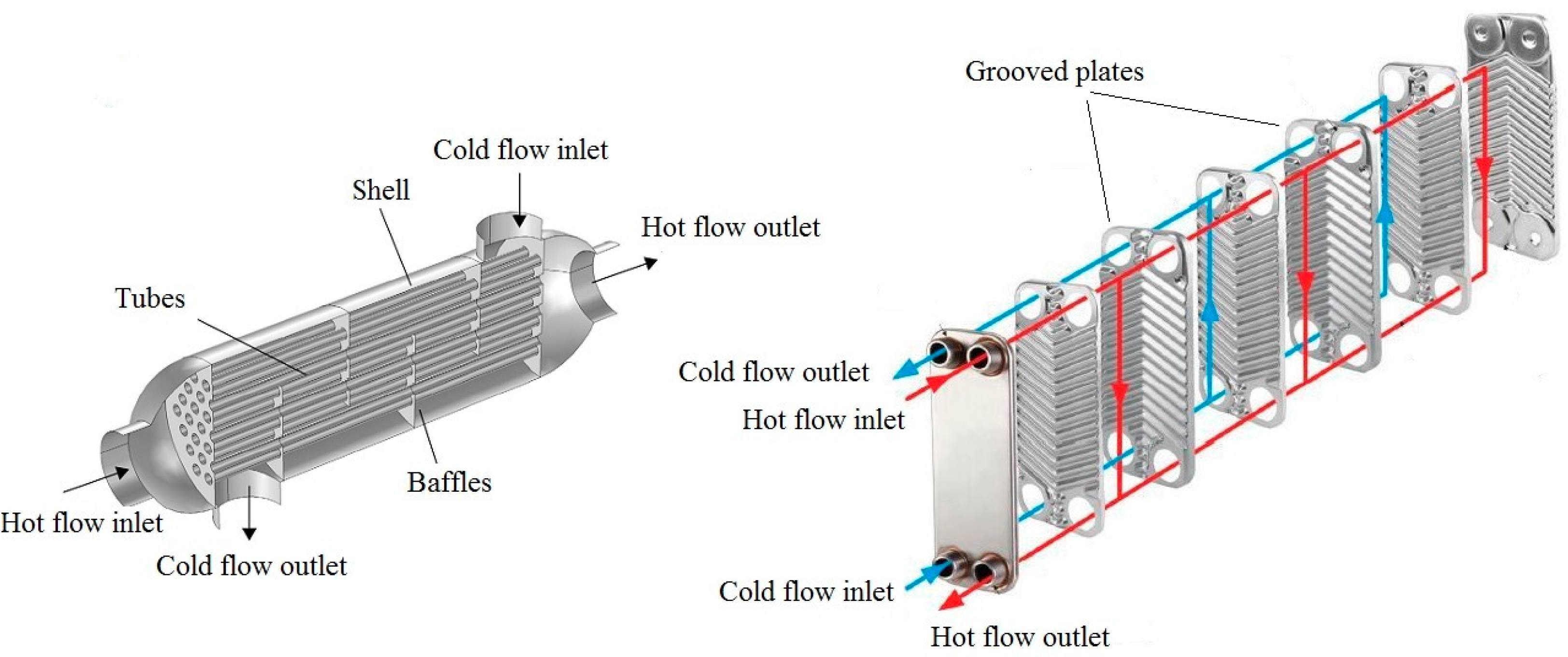
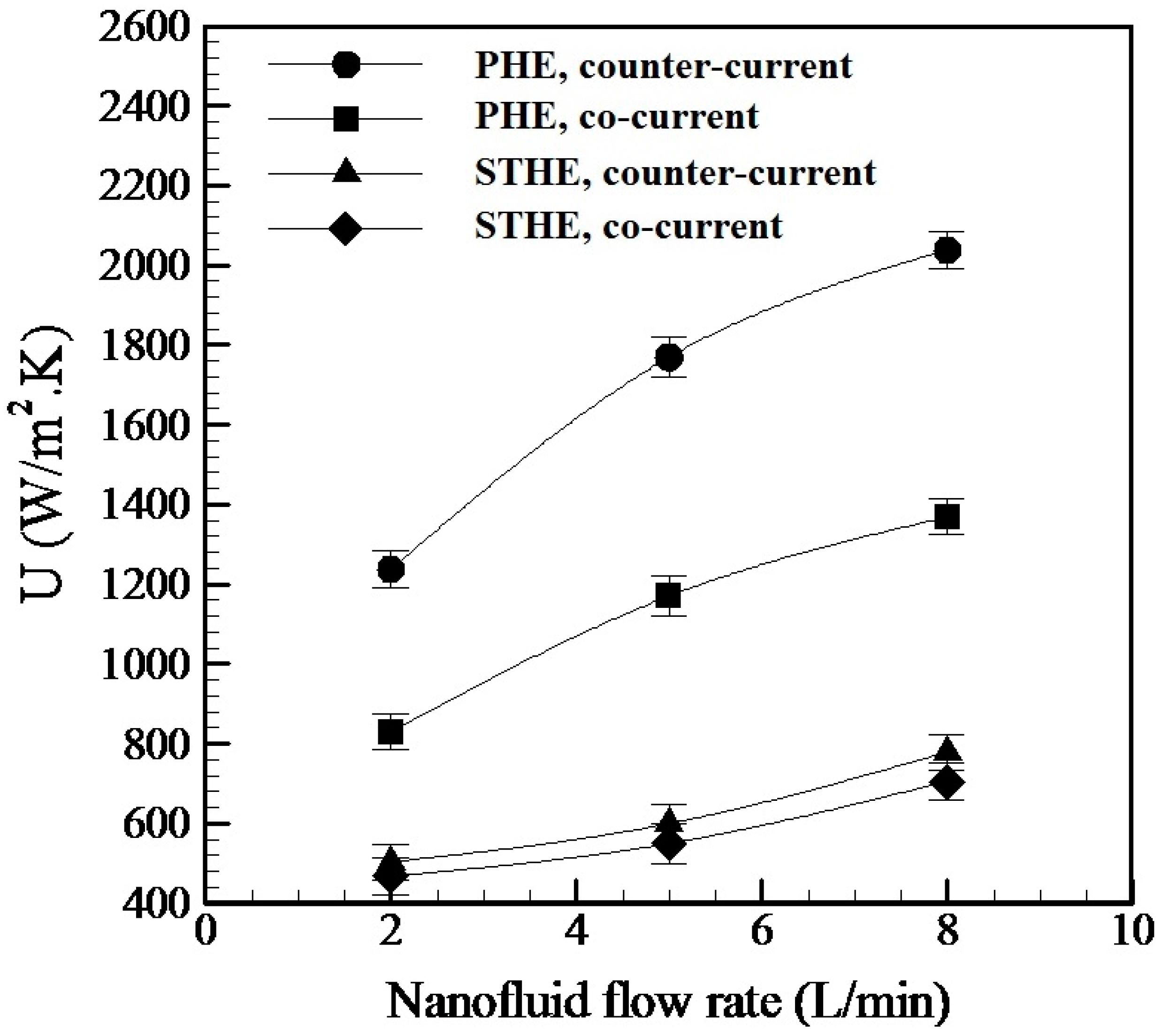
  • PHE creates a higher U value than the STHE at various NF concentrations. The main reason is the existence of grooves on the plates of PHE, which raises the probability of turbulent flow compared to laminar flow in the STHE.
  • Low nanofluid concentrations have a negligible impact on the enhancement of the U value of both PHE and STHE, and the nanofluid flow rate has the highest impact on the U value, just like conventional fluid.
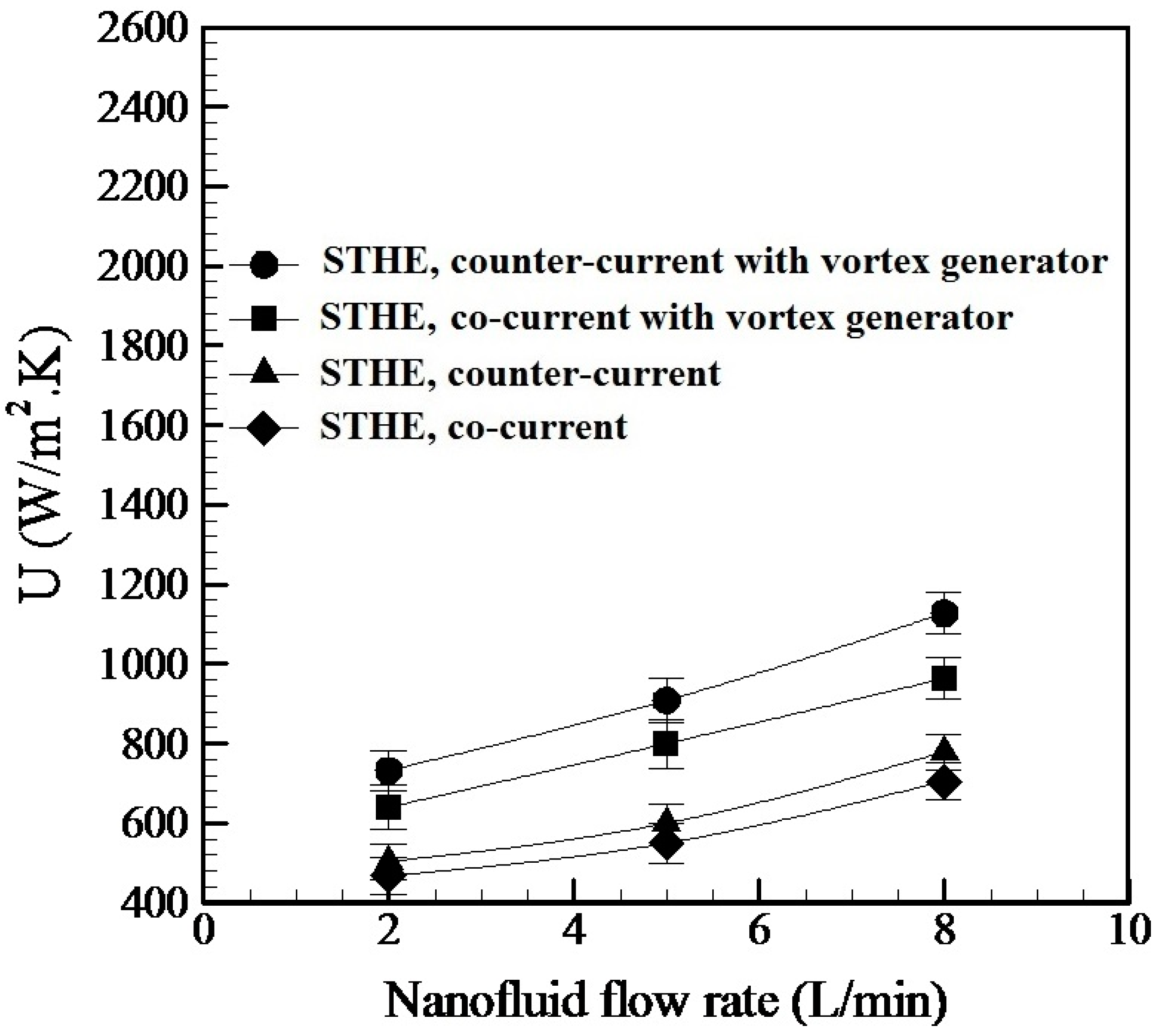
  • Counter-current flow increases the U value for both PHE and STHE. Nevertheless, it has a higher impact on the U value of PHE than the STHE.
  • For both PHE and STHE, increasing the nanofluid flow rate enhances the amount of the U value. Nevertheless, its impact on the PHE U value is more significant than that of STHE.
  • In the whole experiment temperature domain, the PHE shows higher performance than STHE, and when the fluid temperature increases from 36 to 56 °C, there is a slight increase in overall heat transfer of both PHE and STHE.
  • At the same flow rate, both PHE and STHE have almost the same pump power consumption, and increasing the nanofluid flow rate increases the electrical power consumption of the pump.
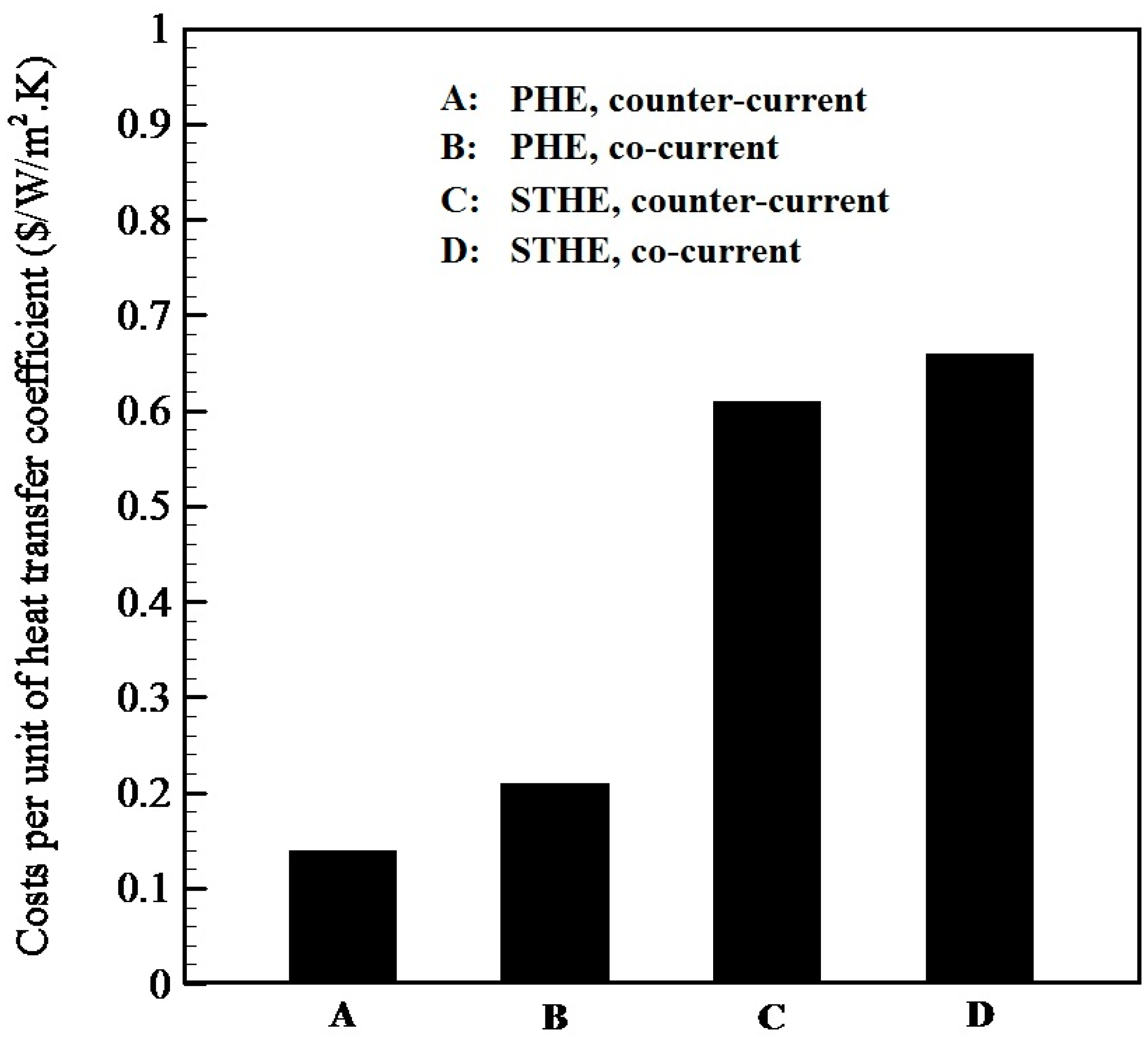
  • The costs per unit of heat transfer coefficient for PHE are significantly smaller than that of STHE.
  • Using a vortex generator at the inlet of STHE tubes for making turbulent flow dramatically increases the U values of STHE for both co-current and counter-current flows.
  • Although turbulent flow increases the U values of STHE, they are lower than the corresponding U values of PHE. Small plates gap in PHE structure which cause higher velocities of fluid flow and create a chain-like structure of NPs between the plates of PHE (especially at higher NF concentrations) are the main reasons for this.
Based on the findings of the present work, a thermal and economic comparative investigation on the effect of using different nanofluids and the also effect of using highhigh-concentrationofluids were suggested as some future research directions.

Author Contributions

Conceptualization, S.H.P. and M.G.; methodology, S.H.P., M.G. and M.B.; formal analysis, S.H.P., M.G. and M.B.; investigation, S.H.P., M.G. and M.B.; resources, S.H.P. and M.G.; data curation, S.H.P., M.G. and M.B.; writing—original draft preparation, S.H.P., M.G. and M.B.; writing—review and editing, S.H.P. and M.B.; visualization, S.H.P. and M.G.; supervision, S.H.P. and M.G. All authors have read and agreed to the published version of the manuscript.

Funding

This research received no external funding.

Data Availability Statement

The data presented in this study are available on request from the corresponding author.

Conflicts of Interest

The authors declare that there are no conflicts of interest regarding the publication of this paper.

References

  1. Masoumpour, B.; Ataeizadeh, M.; Hajabdollahi, H.; ShafieyDehaj, M. Performance evaluation of a shell and tube heat exchanger with recovery of mass flow rate. J. Taiwan Inst. Chem. Eng. 2021, 123, 153–165. [Google Scholar] [CrossRef]
  2. Keramat, F.; Izadpanah, A.B. Thermo-hydraulic performance analysis of converging-diverging heat exchanger with inclined fins using computational fluid dynamics. J. Taiwan Inst. Chem. Eng. 2022, 132, 104119. [Google Scholar] [CrossRef]
  3. Wang, S.; Wen, J.; Li, Y. An experimental investigation of heat transfer enhancement for a shell-and-tube heat exchanger. Appl. Therm. Eng. 2009, 29, 2433–2438. [Google Scholar] [CrossRef]
  4. Hosseini, R.; Hosseini-Ghaffar, A.; Soltani, M. Experimental determination of shell side heat transfer coefficient and pressure drop for an oil cooler shell-and-tube heat exchanger with three different tube bundles. Appl. Therm. Eng. 2007, 27, 1001–1008. [Google Scholar] [CrossRef]
  5. Amini, R.; Amini, M.; Jafarinia, A.; Kashfi, M. Numerical investigation on effects of using segmented and helical tube fins on thermal performance and efficiency of a shell and tube heat exchanger. Appl. Therm. Eng. 2018, 138, 750–760. [Google Scholar] [CrossRef]
  6. Zhang, J.; Zhu, X.; Mondejar, M.E.; Haglind, F. A review of heat transfer enhancement techniques in plate heat exchangers. Renew. Sustain. Energy Rev. 2019, 101, 305–328. [Google Scholar] [CrossRef]
  7. Gut, J.A.W.; Pinto, J.M. Modeling of plate heat exchangers with generalized configurations. Int. J. Heat Mass Transf. 2003, 46, 2571–2585. [Google Scholar] [CrossRef]
  8. Luan, Z.J.; Zhang, J.M.; Tian, M.C.; Fan, M.X. Flow resistance and heat transfer characteristics of a new-type plate heat exchanger. J. Hydrodyn. Ser. B 2008, 20, 524–529. [Google Scholar] [CrossRef]
  9. Mansfield, E.; Tyner, K.M.; Poling, C.M.; Blacklock, J.L. Determination of nanoparticle surface coatings and nanoparticle purity usingmicroscale thermogravimetric analysis. Anal. Chem. 2014, 86, 1478–1484. [Google Scholar] [CrossRef]
  10. Reznickova, A.; Orendac, M.; Kolska, Z.; Cizmar, E.; Dendisova, M.; Svorcik, V. Copper nanoparticles functionalized PE: Preparation, characterization andmagnetic properties. Appl. Surf. Sci. 2016, 390, 728–734. [Google Scholar] [CrossRef]
  11. Stueber, D.D.; Villanova, J.; Aponte, I.; Xiao, Z.; Colvin, V.L. Magnetic nanoparticles in biology and medicine: Past, present, and future trends. Pharmaceutics 2021, 13, 943. [Google Scholar] [CrossRef] [PubMed]
  12. Mohammed, L.; Gomaa, H.G.; Ragab, D.; Zhu, J. Magnetic nanoparticles for environmental and biomedical applications: A review. Particuology 2017, 30, 1–14. [Google Scholar] [CrossRef]
  13. De Crozals, G.; Bonnet, R.; Farre, C.; Chaix, C. Nanoparticles with multiple properties for biomedical applications: A strategic guide. Nano Today 2016, 11, 435–463. [Google Scholar] [CrossRef]
  14. Hofmann-Amtenbrink, M.; Grainger, D.W.; Hofmann, H. Nanoparticles in medicine: Current challenges facing inorganic nanoparticle toxicity assessments and standardizations. Nanomed. Nanotechnol. Biol. Med. 2015, 11, 1689–1694. [Google Scholar] [CrossRef]
  15. Bansal, A.; Zhang, Y. Photocontrolled Nanoparticle Delivery Systems for Biomedical Applications. Acc. Chem. Res. 2014, 47, 3052–3060. [Google Scholar] [CrossRef]
  16. Kim, J.; Mirando, A.C.; Popel, A.S.; Green, J.J. Gene delivery nanoparticles to modulate angiogenesis. Adv. Drug Deliv. Rev. 2017, 119, 20–43. [Google Scholar] [CrossRef]
  17. Ahmad, U.; Tubia, A.; Ahmed, A.I.; Rajesh, K.; Al-Assiri, M.S.; Baskoutas, S.; Akhtar, M.S. An efficient chemical sensor based on CeO2 nanoparticles for the detection of acetylacetone chemical. J. Electroanal. Chem. 2020, 864, 114089. [Google Scholar]
  18. Lan, M.; Zhang, J.; Chui, Y.S.; Wang, P.; Chen, X.; Lee, C.S.; Kwong, H.L.; Zhang, W. Carbon Nanoparticle-based Ratiometric Fluorescent Sensor for Detecting Mercury Ions in Aqueous Media and Living Cells. ACS Appl. Mater. Interfaces 2014, 6, 21270–21278. [Google Scholar] [CrossRef]
  19. Hamidi-Asl, E.; Raoof, J.; Naghizadeh, N.; Sharifi, S.; Hejazi, M. A bimetallic nanocomposite electrode for direct and rapid biosensing of p53 DNA plasmid. J. Chem. Sci. 2015, 127, 1607–1617. [Google Scholar] [CrossRef]
  20. Hussain, M.M.; Rahman, M.M.; Asiri, A.M. Ultrasensitive and selective 4-aminophenol chemical sensor development based on nickel oxide nanoparticles decorated carbon nanotube nanocomposites for green environment. J. Environ. Sci. 2017, 53, 27–38. [Google Scholar] [CrossRef]
  21. Hamidi-Asl, E.; Palchetti, I.; Hasheminejad, E.; Mascini, M. A review on the electrochemical biosensors for determination of microRNAs. Talanta 2013, 115, 74–83. [Google Scholar] [CrossRef] [PubMed]
  22. Thabet, A.; Mobarak, Y. The effect of cost-fewer nanoparticles on the electrical properties of polyvinyl chloride. Electr. Eng. 2017, 99, 625–631. [Google Scholar] [CrossRef]
  23. Hu, S.; Zhou, Y.; Yuan, C.; Wang, W.; Hu, J.; Li, Q.; He, J. Surface-modification effect of MgO nanoparticles on the electrical properties of polypropylene nanocomposite. High Volt. 2020, 5, 249–255. [Google Scholar] [CrossRef]
  24. Gajendiran, M.; Choi, J.; Kim, S.J.; Kim, K.; Shin, H.; Koo, H.J.; Kim, K. Conductive biomaterials for tissue engineering applications. J. Ind. Eng. Chem. 2017, 51, 12–26. [Google Scholar] [CrossRef]
  25. Sabr, O.H.; Kadhim, H.J.; Salman, M.M. Studying the effect of silica nanoparticles on optical properties of polyvinyl alcohol thin films for semiconductors applications. Test Eng. Manag. 2020, 83, 11014–11019. [Google Scholar]
  26. Kiarii, E.M.; Govender, K.K.; Ndungu, P.G.; Govender, P.P. The generation of charge carriers in semi-conductors—A theoretical study. Chem. Phys. Lett. 2017, 678, 167–176. [Google Scholar] [CrossRef]
  27. Wang, F.; Zhang, C.; Liu, J.; Fang, X.; Zhang, Z. Highly stable graphite nanoparticle-dispersed phase change emulsions with little supercooling and high thermal conductivity for cold energy storage. Appl. Energy 2016, 188, 97–106. [Google Scholar] [CrossRef]
  28. Fan, F.Y.; Woodford, W.H.; Li, Z.; Baram, N.; Smith, K.C.; Helal, A.; McKinley, G.H.; Carter, W.C.; Chiang, Y.M. Polysulfide Flow Batteries Enabled by Percolating Nanoscale Conductor Networks. Nano Lett. 2014, 14, 2210–2218. [Google Scholar] [CrossRef]
  29. Park, J.; Kewon, T.; Kim, J.; Jin, H.; Kim, H.Y.; Kim, B.; Joo, S.H.; Lee, K. Hollow nanoparticles as emerging electrocatalysts for renewable energy conversion reactions. Chem. Soc. Rev. 2018, 47, 8173–8202. [Google Scholar] [CrossRef]
  30. Liu, M.; Wang, X.; Zhu, D.; Li, L.; Duan, H.; Xu, Z.; Wang, Z.; Gan, L. Encapsulation of NiO nanoparticles in mesoporous carbon nanospheres for advanced energy storage. Chem. Eng. J. 2016, 308, 240–247. [Google Scholar] [CrossRef]
  31. Ağbulut, Ü.; Sarıdemir, S. A general view to converting fossil fuels to cleaner energy source by adding nanoparticles. Int. J. Ambient. Energy 2021, 42, 1569–1574. [Google Scholar] [CrossRef]
  32. Mahdi, J.M.; Nsofor, E.C. Melting enhancement in triplex-tube latent heat energy storage system using nanoparticles-metal foam combination. Appl. Energy 2016, 191, 22–34. [Google Scholar] [CrossRef]
  33. Elnaqeeb, T.; Ali Shah, N.; Vieru, D. Heat transfer enhancement in natural convection flow of nanofluid with Cattaneo thermal transport. Phys. Scr. 2020, 95, 115705. [Google Scholar] [CrossRef]
  34. Hajmohammadi, M.R.; Tork, M.H.M.A. Effects of the magnetic field on the cylindrical Couette flow and heat transfer of a nanofluid. Phys. Scr. 2019, 523, 234–245. [Google Scholar] [CrossRef]
  35. Pourhoseini, S.H.; Ramezani-Aval, H.; Naghizadeh, N. FHD and MHD effects of Fe3O4-water magnetic nanofluid on the enhancement of overall heat transfer coefficient of a heat exchanger. Phys. Scr. 2020, 95, 045705. [Google Scholar] [CrossRef]
  36. Sheikholeslami, M.; Jafaryar, M.; Shafee, A.; Li, Z. Nanoparticles for water desalination in solar heat exchanger. J. Therm. Anal. Calorim. 2018, 134, 2295–2303. [Google Scholar] [CrossRef]
  37. Wei, B.; Zou, C.; Li, X. Experimental investigation on stability and thermal conductivity of diathermic oil based TiO2 nanofluids. Int. J. Heat Mass Transf. 2017, 104, 537–543. [Google Scholar] [CrossRef]
  38. Gkountas, A.A.; Benos, L.T.; Sofiadis, G.N.; Sarris, I.E. A printed-circuit heat exchanger consideration by exploiting an Al2O3-water nanofluid: Effect of the nanoparticles interfacial layer on heat transfer. Therm. Sci. Eng. Prog. 2021, 22, 100818. [Google Scholar] [CrossRef]
  39. Atashafrooz, M. Effects of Ag-water nanofluid on hydrodynamics and thermal behaviors of three-dimensional separated step flow. Alex. Eng. J. 2018, 57, 4277–4285. [Google Scholar] [CrossRef]
  40. Harish, R.; Sivakumar, R. Turbulent thermal convection of nanofluids in cubical enclosure using two-phase mixture model. Int. J. Mech. Sci. 2021, 190, 106033. [Google Scholar] [CrossRef]
  41. Farajollahi, B.; Etemad, S.G.; Hojjat, M. Heat transfer of nanofluids in a shell and tube heat exchanger. Int. J. Heat Mass Transf. 2010, 53, 12–17. [Google Scholar] [CrossRef]
  42. Elias, M.M.; Shahrul, I.M.; Mahbubul, I.M.; Saidur, R.; Rahim, N.A. Effect of different nanoparticle shapes on shell and tube heat exchangerusing different baffle angles and operated with nanofluid. Int. J. Heat Mass Transf. 2014, 70, 289–297. [Google Scholar] [CrossRef]
  43. Bahiraei, M.; Naseri, M.; Monavari, A. Thermal-hydraulic performance of a nanofluid in a shell-and-tube heat exchanger equipped with new trapezoidal inclined baffles: Nanoparticle shape effect. Powder Technol. 2022, 395, 348–359. [Google Scholar] [CrossRef]
  44. Anitha, S.; Thomas, T.; Parthiban, V.; Pichumani, M. What dominates heat transfer performance of hybrid nanofluid in single 5 pass shell and tube heat exchanger? Adv. Powder Technol. 2019, 30, 3107–3117. [Google Scholar] [CrossRef]
  45. Bahiraei, M.; Monavari, A. Thermohydraulic performance and effectiveness of a mini shell and tube heat exchanger working with a nanofluid regarding effects of fins and nanoparticle shape. Adv. Powder Technol. 2021, 32, 4468–4480. [Google Scholar] [CrossRef]
  46. Huang, D.; Wu, Z.; Sunden, B. Effects of hybrid nanofluid mixture in plate heat exchangers. Exp. Therm. Fluid Sci. 2016, 72, 190–196. [Google Scholar] [CrossRef]
  47. Taghizadeh-Tabari, Z.; ZeinaliHeris, S.; Moradi, M.; Kahani, M. The study on application of TiO2/water nanofluid in plate heatexchanger of milk pasteurization industries. Renew. Sustain. Energy Rev. 2016, 58, 1318–1326. [Google Scholar] [CrossRef]
  48. Barzegarian, B.; Keshavarz Moraveji, M.; Aloueyan, A. Experimental investigation on heat transfer characteristics and pressure drop of BPHE (brazed plate heat exchanger) using TiO2-water nanofluid. Exp. Therm. Fluid Sci. 2016, 74, 11–18. [Google Scholar] [CrossRef]
  49. Bhattad, A.; Sarkar, J.; Ghosh, P. Heat transfer characteristics of plate heat exchanger using hybrid nanofluids: Effect of nanoparticle mixture ratio. Heat Mass Transf. 2020, 56, 2457–2472. [Google Scholar] [CrossRef]
  50. Hajabdollahi, H.; Ataeizadeh, M.; Masoumpour, B.; ShafieyDehaj, M. Comparison of the effect of various nanoparticle shapes on optimal design of plate heat exchanger. Heat Transf. Res. 2021, 52, 29–47. [Google Scholar] [CrossRef]
  51. Gürbüz, E.Y.; Sözen, A.; Variyenli, H.I.; Khanlari, A.; Tuncer, A.D. A comparative study on utilizing hybrid-type nanofluid in plate heat exchangers with different number of plates. J. Braz. Soc. Mech. Sci. Eng. 2020, 42, 524. [Google Scholar] [CrossRef]
  52. Sözen, A.; Khanları, A.; Çiftçi, E.; Sözen, A. Heat transfer enhancement of plate heat exchanger utilizing kaolin-including working fluid. J. Power Energy 2019, 233, 626–634. [Google Scholar] [CrossRef]
  53. Buszewski, B.; Rafiſska, K.; Pomastowski, P.; Walczak, J.; Rogowska, A. Novel aspects of silver nanoparticles functionalization. Colloids Surf. A Physicochem. Eng. Asp. 2016, 506, 170–178. [Google Scholar] [CrossRef]
  54. Guo, Z.; Chen, G.; Zeng, G.; Yan, M.; Huang, Z.; Jiang, L.; Peng, C.; Wang, J.; Xiao, Z. Are silver nanoparticles always toxic in the presence of environmental anions? Chemosphere 2016, 171, 318–323. [Google Scholar] [CrossRef] [PubMed]
  55. Pourhoseini, S.H.; Naghizadeh, N.; Hoseinzadeh, H. Effect of silver-water nanofluid on heat transfer performance of a plate heat exchanger: An experimental and theoretical study. Powder Technol. 2018, 332, 279–286. [Google Scholar] [CrossRef]
Figure 1. AFM image of Ag NPs. * shows axis direction.
Energies 16 01854 g001
Figure 2. Schematic of the test setup.
Energies 16 01854 g002
Figure 3. Geometrical configuration of STHE (left) and PHE (right).
Energies 16 01854 g003
Figure 4. Comparison of U value for PHE and STHE at different NF concentrations.
Energies 16 01854 g004
Figure 5. Impact of NF flow rate on U value for PHE and STHE.
Energies 16 01854 g005
Figure 6. Performance of PHE and STHE at different temperatures of Ag-H2O NF.
Energies 16 01854 g006
Figure 7. Electrical power consumption of the pump for PHE and STHE.
Energies 16 01854 g007
Figure 8. Comparison of heat transfer costs for PHE and STHE.
Energies 16 01854 g008
Figure 9. Comparison of the U values for STHE with and without vortex generators.
Energies 16 01854 g009
Table 1. PHE specification.
PropertyValue
Plates area0.21 m2
Plates materialStainless steel 316(L)
Plates gap (b)2.5 mm
Plate height193 mm
Plate width (W)83 mm
Plate thickness0.5 mm
Table 2. STHE specification.
PropertyValue
Total heat transfer area0.21 m2
Tubes materialStainless steel 316(L)
Number of tubes30
Tube length450 mm
Tube ID (Inner Diameter)4 mm
Disclaimer/Publisher’s Note: The statements, opinions and data contained in all publications are solely those of the individual author(s) and contributor(s) and not of MDPI and/or the editor(s). MDPI and/or the editor(s) disclaim responsibility for any injury to people or property resulting from any ideas, methods, instructions or products referred to in the content.

