Article

Dynamic Response Difference of Hydraulic Support under Mechanical-Hydraulic Co-Simulation: Induced by Different Roof Rotation Position and Hysteresis Effect of Relief Valve

1
College of Mechanical and Electronic Engineering, Shandong University of Science and Technology, Qingdao 266590, China
2
College of Science and Engineering, Shandong Normal University, Jinan 250014, China
3
State Key Laboratory of Mining Disaster Prevention and Control Cofounded by Shandong Province and the Ministry of Science and Technology, Shandong University of Science and Technology, Qingdao 266590, China
*
Author to whom correspondence should be addressed.
Energies 2023, 16(4), 2052; https://doi.org/10.3390/en16042052
Submission received: 14 December 2022 / Revised: 4 February 2023 / Accepted: 16 February 2023 / Published: 19 February 2023
(This article belongs to the Topic Mining Safety and Sustainability)

Abstract

:
As key supporting equipment in coal mining, hydraulic supports are vulnerable to impact pressure from roof movement and deformation. In this paper, a mechanical-hydraulic co-simulation platform for hydraulic supports is established. Moreover, the rationality of the simulation platform is verified. Based on this platform, the rigid-flexible coupling impact dynamics model of hydraulic support is built. Finally, by delaying the opening time of the relief valve, the energy dissipation problem of the relief valve hysteresis effect on the hydraulic support system under the rotary impact is discussed. The results indicate that the rotary load acting on the hydraulic support decreases gradually with the backward movement of the roof rotary position, which causes the peak pressure in the column to decrease (by 69 MPa). The hinge point load of different parts shows different load transfer laws. The hysteresis effect of the relief valve prolongs the energy release time of the system, increasing the pressure in the column by 23 MPa. The instantaneous opening speed of the relief valve spool reaches 15.7 m/s, and the hinge point between the top beam and the column is most sensitive to the hysteresis effect (impact coefficient increases by 0.63).

1. Introduction

Safe mining and effective coal utilization are critical factors determining national economic development and social progress [1]. Due to its simple construction, lightweight, and elevated support efficiency, the two-column hydraulic support has become one of the main supporting devices [2]. Owing to the effects of roof movement laws, surrounding rock properties, mining heights, and the rate of advance of the working face, the main roof above the hydraulic support breaks frequently at different locations [3]. Therefore, hydraulic supports are subject to various sudden changes or alternating loads during the support [4,5].
Numerous scholars have discussed two aspects of mechanical and hydraulic systems and analyzed the dynamic response characteristics and load-bearing properties of hydraulic supports under impact load. In the aspect of the mechanical system of the hydraulic support, Liang et al. [6] completed an in-depth study on the force transfer laws under impact load. Moreover, the author explained that the load at different positions of the top beam and load application methods affected the load transmission characteristics of the hinge point. Based on the ZF56000/16.5/26 top coal caving hydraulic support and ZY21000/38/82D shield hydraulic support, Zeng et al. [7,8] established dynamic simulation models and analyzed the bearing characteristics under different loading forms and support heights. The results can be used as a reference for designing hydraulic support strength. Zhao et al. [9] observed that when the elevated low-use hydraulic support with a large mining height or the shield beam was impacted by the roof caving, the top beam and the shield beam could easily reach the limit position and form a straight line. Consequently, the shield beam was damaged, and the support lost its support ability. Ren et al. [10] cross-validated the results by building a 1:2 multi-scale experimental model of the hydraulic support to obtain the law of energy dissipation characteristics of the hydraulic support under impact load. The authors found that the initial force and column stiffness modified the energy redistribution ratio under impact load. Zeng et al. [11,12] established numerical simulation models with two-column and four-column hydraulic supports. Then, key components, such as top beam beams, were flexibly processed to explore the load transfer characteristics under different impact conditions. Wan et al. [13,14] proposed a new self-adaptive balance jack structure with a buffer cavity. By optimizing the diameter and number of unloading holes and the length of the buffer cavity, the impact resistance of the hydraulic support was further improved. Zhao and Yang et al. [15,16] studied the rigid-flexible coupling model of the hydraulic support tail beam. The influence of coal gangue material, impact position, and contact form on the load variation coefficient of the hinge point and the stress variation characteristics of key components were analyzed.
In the aspect of the hydraulic system of the hydraulic support, Zuo et al. [17] proposed two sealing methods, column piston combined sealing and drum sealing, to solve the problem of poor hydraulic support column system sealing and provide a different idea for improving the supporting capacity of hydraulic supports. Zeng and Liu et al. [18,19] established a two-way fluid-solid coupling model of the hydraulic support column and analyzed the liquid flow inside the column cavity under impact loads. The results showed that the fluid flow rate increased with the impact on the bottom of the cylinder. Song and Zhao et al. [20,21] studied the safety valve connected to the column cavity. They analyzed the sensitivity response characteristics of the safety valve under different spool masses, spring stiffnesses, and load impacts. The study was of practical significance for improving the reliability of the safety valve and hydraulic support. Li and Cai et al. [22,23] developed a simulation model of the hydraulic support column hydraulic system based on AMESim. The authors analyzed the bearing characteristics of the columns under different external loads. They pointed out that the stability of the hydraulic support could be improved by adding the spring stiffness of the safety valve. Cao et al. [24] designed a column automatic pressurization device to improve the impact resistance of the hydraulic support, prevent the hydraulic support column from roof collapse during the support process, and reduce the occurrence of rock bursts.
The application of multi-software co-simulation technology has also attracted the attention of some scholars. Zhang et al. [25] built a crane mechanical-hydraulic co-simulation platform based on NX and AMESim. The authors compared the simulation results with a single hydraulic simulation result and pointed out that the co-simulation can improve considerably the analysis accuracy. He et al. [26] used Automation Studio to establish a mechanical-electrical-hydraulic co-simulation model of a wet spraying machine and successfully simulated the sequential action process of the manipulator, which provided a reference for co-simulation in additional fields. Huang et al. [27] took the scissors mechanism as the research object and proposed the method of building a mechanical and hydraulic co-simulation model based on Virtual Lab and AMESim, and tested the inlet pressure of the hydraulic cylinder to verify the correctness of the model’s accuracy. Li et al. [28] proposed the mechanical-hydraulic coupling model of the rope regulator by ADAMS and AMESim and analyzed the dynamic characteristics of the cylinder pressure change under the tension and relaxation of the wire rope. Lu et al. [29] investigated the automatic ammunition supply system using RecurDyn, AMESim, and Simulink, which improved efficiency and reduced the cost of the study.
To summarize, scholars at home and abroad have taken two-column or four-column hydraulic supports as the research object and analyzed the regional stress change state of the hydraulic support mechanical system, load transfer law, and dynamic response characteristics of crucial components in the hydraulic system. Using these results, they proposed measures to improve the stability and impact resistance of supports. However, the effect of mechanical structure motion under impact load on the response characteristics of the hydraulic system has not been considered. Moreover, the influence of a hydraulic system as a complex series–parallel system, including multiple hydraulic cylinders such as the column and balance jack, on the stability of the mechanical system during action coupling has not been analyzed. In addition, the method of multi-software co-simulation is less applied in hydraulic supports. Therefore, this paper uses ADAMS, AMESim, and Simulink to build a mechanical-hydraulic co-simulation platform for the two-column hydraulic support, which analyzes the collaborative working characteristics of the hydraulic support under the impact of roof rotation. The mechanical system is set up by ADAMS, the hydraulic system by AMESim, and the data coupling between the mechanical and hydraulic systems is implemented by Simulink. The effect of different roof rotation positions and the hysteresis effect of the relief valve on the dynamic characteristics of the mechanical-hydraulic cooperative system is analyzed, which provides the basis for the structural optimization and adaptive design of the hydraulic support.

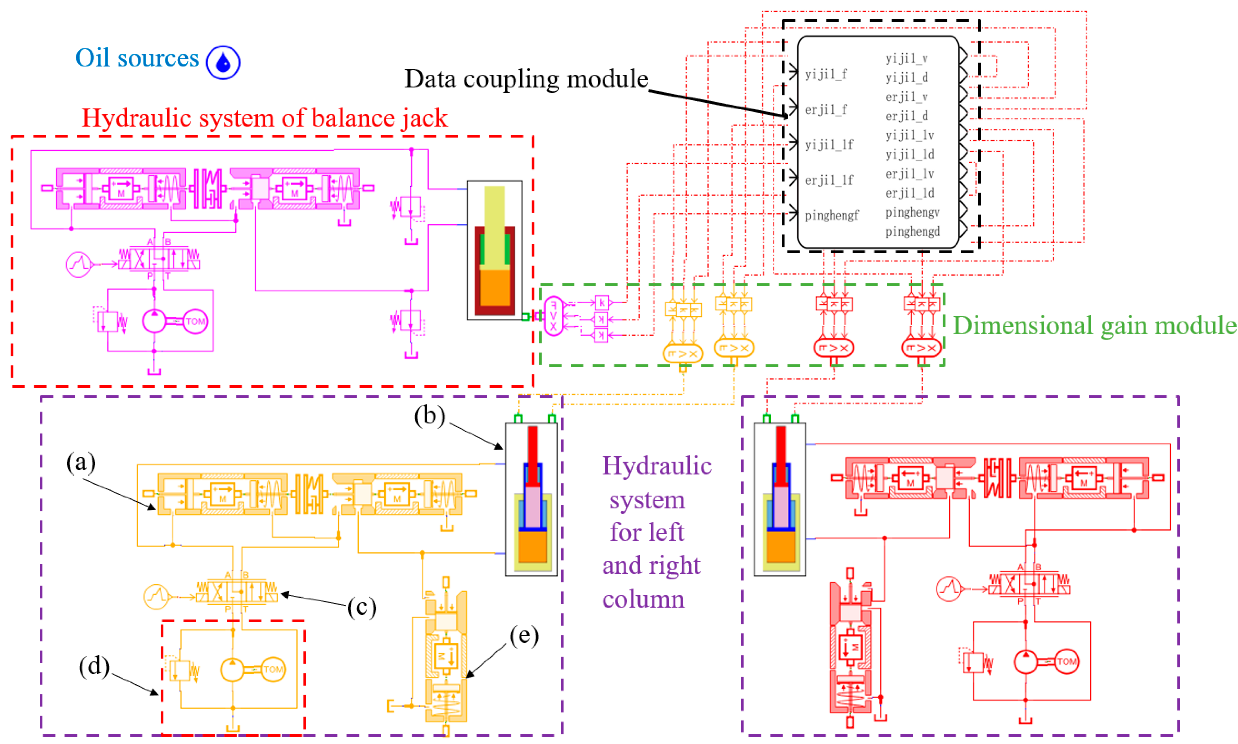
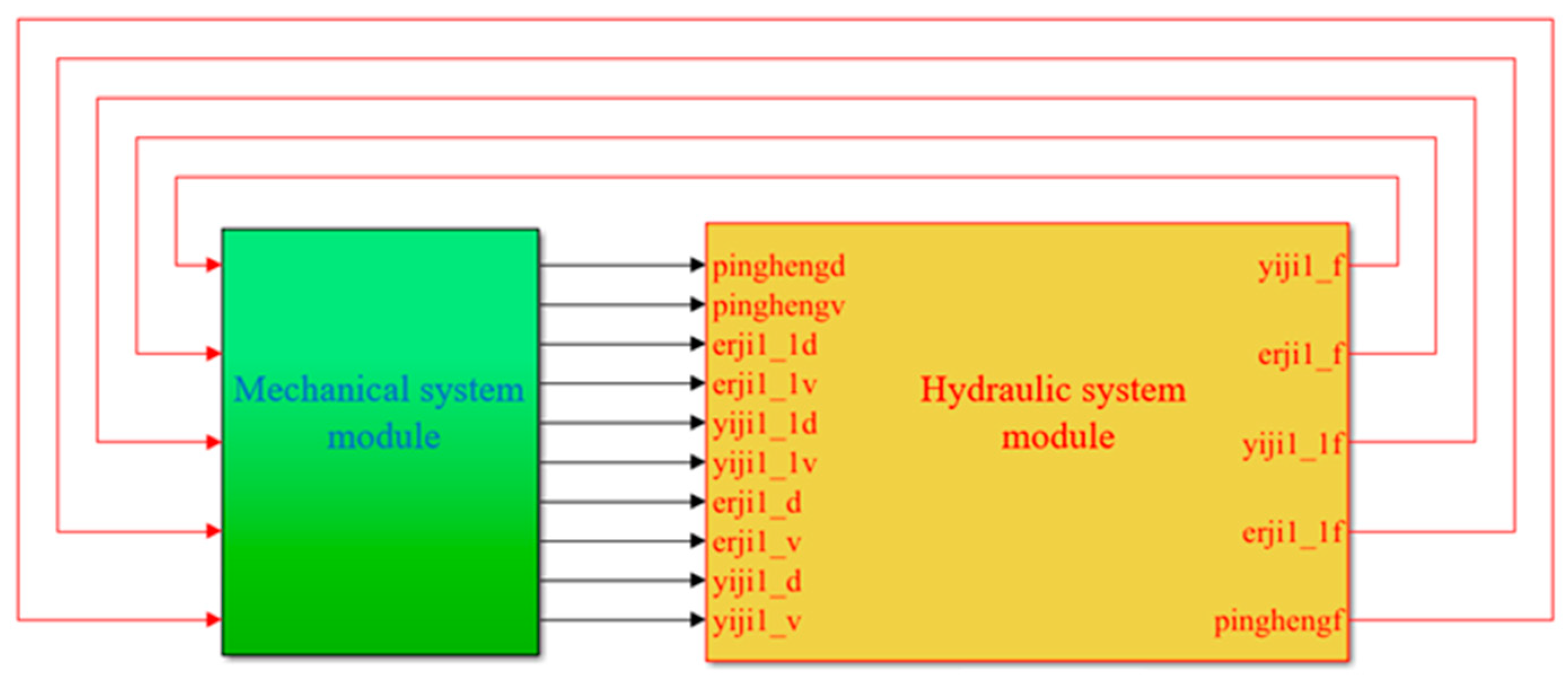
2. The Mechanical-Hydraulic Co-Simulation Platform

2.1. The Mechanical System Model

In this paper, the ZY21000/38/82D hydraulic support is taken as the research object, and the mechanical system model of the hydraulic support is established via the multi-body dynamics ADAMS. The structural parameters and technical parameters of the hydraulic support are shown in Table 1 and Table 2. Firstly, the 3D structural model of the hydraulic support is imported into ADAMS, and each component is constrained individually. The joint motion between the column hydraulic cylinder and the balance jack cylinder is constrained as a moving pair, the base and the ground are the fixed pair, and the remaining components are constrained as a rotating pair. Mark points are established at the bottom of the first-stage cylinder, the second-stage cylinder, the balance jack cylinder, and the piston to achieve the interaction of hydraulic cylinder speed, displacement, and force between different software, as shown in Figure 1. Based on the above mark points, the state variables of the system units are created according to Table 3. The solver is set to C++, the target software is MATLAB, and the analysis type is non-linear.

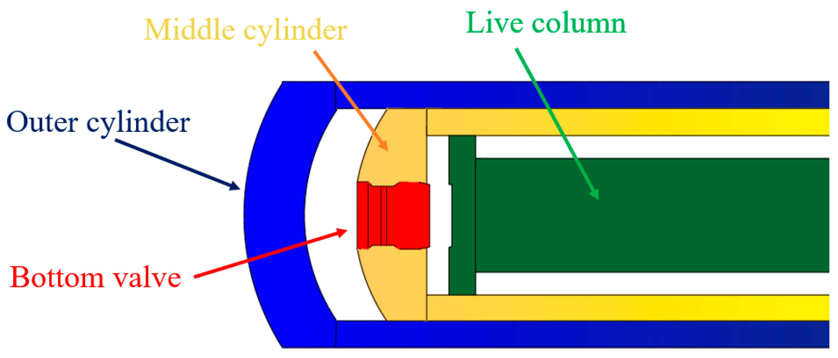
2.2. The Hydraulic System Model

This section shows the use of AMESim to build the hydraulic system model for the hydraulic support. A dimensional gain module is introduced to match the variable dimensions and consider the difference between the software variable dimensions. The hydraulic circuit diagram is shown in Figure 2. A model of the completed hydraulic system is shown in Figure 3. The dimension parameters of the hydraulic cylinder are shown in Table 4.
Based on the above mechanical and hydraulic system models, the mechanical and hydraulic system modules for the hydraulic support are derived using MATLAB/Simulink. The solver in ADAMS Plant is set to C++, and the communication time is 0.0001 s. The interaction simulation model is chosen, and the variable step size ode45 function is chosen in the Simulink solver. The co-simulation platform for the hydraulic support based on the mechanical and hydraulic system modules is shown in Figure 4.

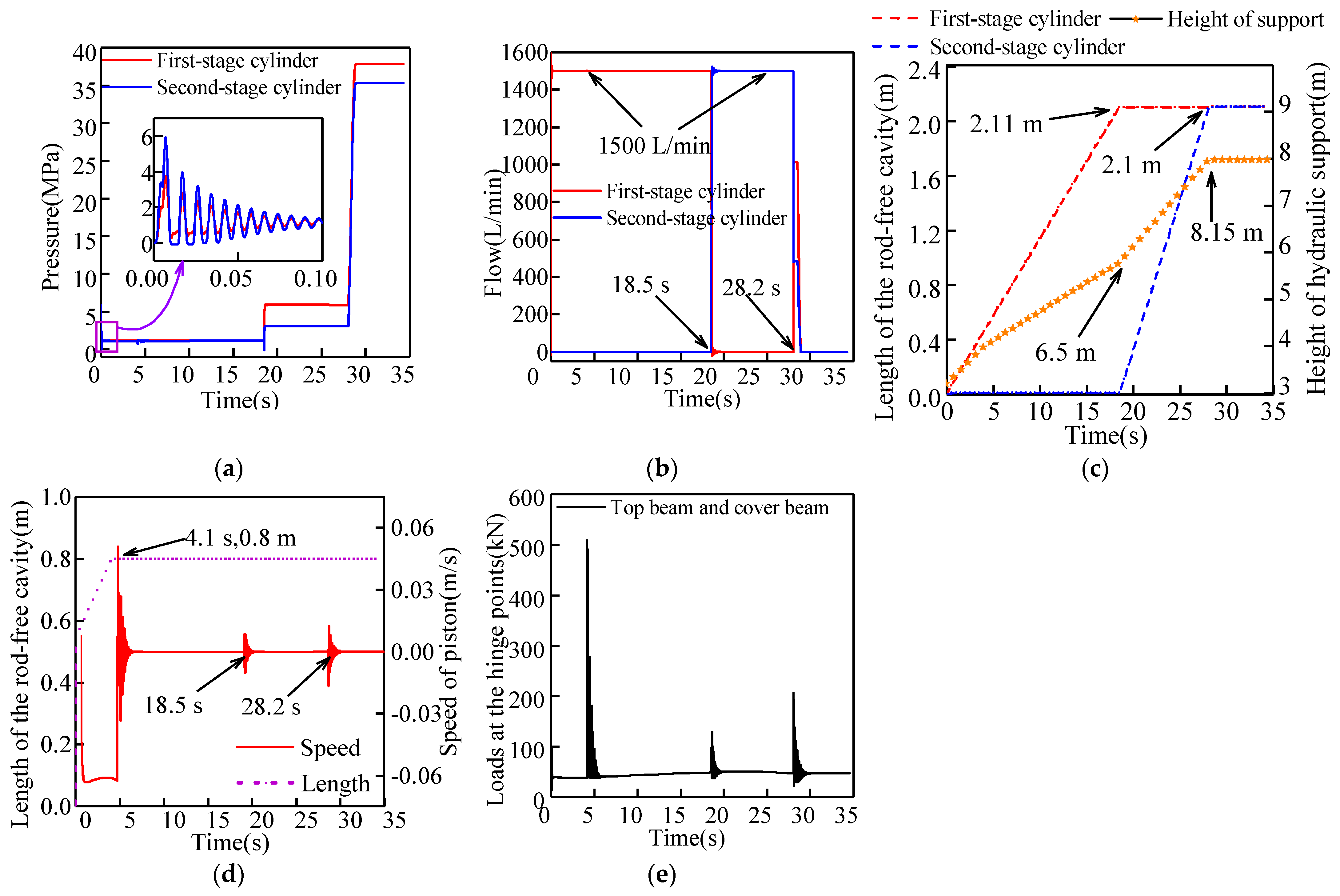
2.3. Simulation of the Hydraulic Support Lifting Process

The main purpose of this section is to verify the rationality of the collaborative simulation platform by simulating the hydraulic support lifting process. During the test, the external load of the hydraulic support is ignored, and only gravity is considered. The rated flow rate of the pump station is set to 1500 L/min, the initial height of the hydraulic support is 3.2 m, and the simulation operation time is 35 s.
During this simulation, hydraulic oil continues to enter the lower chamber of the column. Figure 5 shows the results of the mechanical-hydraulic coordinated response of the hydraulic support during the lifting process. It can be seen that the first-stage cylinder piston rises during 0~18.5 s. The hydraulic support is in an initial equilibrium gravitational state at the initial rising stage. Therefore, a slight pressure fluctuation exists inside the rod-free cavity, after which the rising pressure of the column stabilizes gradually. During this period, the pressure in the rod-free chamber of the first-stage cylinder is essentially stable at about 1.2 MPa (slightly higher than the gravity of the structural parts). At this stage, the input flow of the rod-free chamber of the first cylinder of the column is 1500 L/min (equal to the rated flow of the pumping station). Due to the bottom valve between the first and secondary cylinders (opening pressure of 2.5 MPa), the input flow of the second-stage cylinder is zero. The position of the bottom valve is shown in Figure 6. Interpretations of the bottom valve are as follows. The bottom valve controls the rising sequence of the column to ensure that the column has the same working resistance throughout the stroke, which directly affects the bearing capacity and reliability of the column. The bottom valve mainly consists of the spool, valve body, filter, spring, and various seals and connections. The bottom valve is placed at the bottom of the middle cylinder of the double telescopic column. When the difference in liquid pressure between the inside and outside of the middle cylinder exceeds the opening pressure of the bottom valve, the liquid force acting on the spool will overcome the spring force and open the liquid hole, allowing the high-pressure liquid in the outer cylinder to enter the middle cylinder.
At 18.5 s, the first-stage cylinder reaches the end of the stroke, the length of the rod-free cavity becomes 2.11 m, and the hydraulic support height rises to approximately 6.5 m. From 18.5 s to 28.2 s, the piston rises to the second-stage cylinder. After the first-stage cylinder reaches the end of the stroke, the chamber pressure rises continuously to open the bottom valve. At this time, the pressure in the rod-less chamber of the first-stage cylinder is stable at 5.9 MPa, and the pressure of the second-stage cylinder is stable at 3.1 MPa (there is a flow gradient pressure of 0.3 MPa). Moreover, the oil intake of the second-stage cylinder rod-free chamber is 1500 L/min.
At 28.2 s, the second-stage cylinder reaches the end of the stroke. At this point, the length of the rod-free cavity of the second-stage cylinder becomes 2.1 m, and the height of the hydraulic support reaches about 8.15 m. During 28.2~35 s, the column piston is moved to the end of the stroke, and the height of the hydraulic support does not alter. However, the initial support force of the hydraulic support is not reached, and the lower chamber of the column does not reach the rated pressure of the pumping station. Therefore, there is still a small amount of hydraulic oil entering the lower chamber of the column in a short time. In addition, the pressure also increases and finally stabilizes near the rated pressure of the pumping station. In other words, the pressure of the rod-free cavity of the first-stage cylinder is stable at 37.8 MPa and the rod-free cavity of the second-stage cylinder is stable at 35.3 MPa (once the pressure stabilizes, no hydraulic oil enters the cavity, and the pressure difference between the rod-free cavity of the first-stage and the second-stage cylinder is only the opening pressure of the bottom valve).
The balance jack piston is passively stretched since it is in an autonomous closed state and is affected by the action of the column (the change of the hydraulic support height). Hence, the length of the rod-free cavity increases, and the piston speed fluctuates. The balance jack piston moves to the end of its stroke at 4.1 s, with large fluctuations in piston speed. Then, at the end of the motion of the first and second cylinders of the column, the piston speed fluctuates slightly. As can be seen in Figure 5e, the curve fluctuates at the beginning or end of the piston displacement of the column and the balancing jack, especially around 4.1 s. The maximum load is 500 kN, and the rest time is roughly stable at around 45 kN.

3. Dynamic Characteristics Analysis of the Hydraulic Support under Rotary Impact

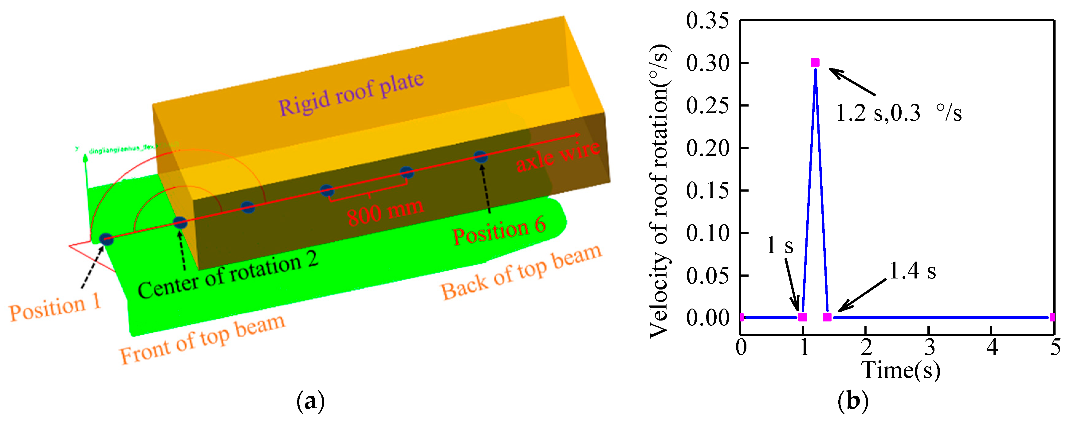
3.1. Establishment of the Rigid-Flexible Coupling Dynamic Model of the Hydraulic Support

The working height of the hydraulic support is selected as 7.5 m. Considering that the impact load generated by the rotation of the roof rotation may cause slight deformation of the key components of the hydraulic support, the top beam, the shield beam, the front connecting rod, and the rear connecting rod, they are flexibly treated using HyperMesh. The above components mesh with the given material properties (density of 7860 kg/m3, Young’s modulus of 2.1 × 10¹¹ Pa, Poisson’s ratio of 0.3), and the rigid body area is established. The flexible processing results of the key components are shown in Figure 7. The established flexible body components are imported into the mechanical model of the hydraulic support. The positions of the flexible body component are constrained by the three-point positioning method to transfer loads.
To analyze the differences in the mechanical-hydraulic cooperative response characteristics of the hydraulic support at different roof rotation positions, six location points (spaced 800 mm apart) are selected along the central axis from the front of the roof beam to the rear of the roof beam. Then, a rigid body roof is established above the top beam (the roof must ensure that it can rotate freely in the height direction of hydraulic support without eccentric load). These six position points are used as the rotation center points of the roof. In addition, the collision contact is set between the top beam and the roof, and the collision parameters are as follows: K = 105 N/mm, damping coefficient is c = 103 N−s/mm, the penetration depth is 1 mm, and the force index is e = 2.2. The STEP function controls the rotational velocity and rotation time of the roof, where 0 s to 1 s is the initial support phase. During this process, the roof’s position is fixed in space, and the top beam of the hydraulic support rises slowly with the entry of the high-pressure oil in the lower chamber of the column, which is closely attached to the roof. During 1~1.2 s, the rotation of the overlying roof accelerates and reaches a peak rotation velocity of 0.3°/s. During 1.2~1.4 s, the roof decelerates and rotates, and the final velocity decreases to zero. The roof rotation position and rotation speed curves are shown in Figure 8.

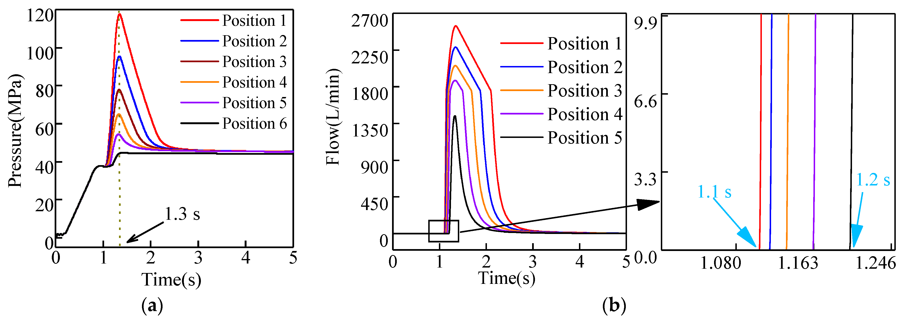
3.2. Effect of the Rotary Position on the Column System

As a key component in the hydraulic system, the column plays an influential role in the height shift and dynamic bearing of the hydraulic support. When the impact load caused by the roof acts on the hydraulic support, the column is generally the most important energy-absorbing frame, which will bear a significant instantaneous pressure. At this point, the relief valve, as the most prominent energy discharge element, plays a crucial role in improving the shock resistance of the column [30].
According to Figure 9, during the initial support phase of hydraulic support, the piston in the cylinder rises as the high-pressure oil continues to enter, driving the top beam into contact with the overlying roof. At this point, the change in the height of the hydraulic support is blocked, and the pressure in the column continues to increase. Finally, the pressure reaches the rated pressure of 37.5 MP. 1~1.4 s is the stage of the roof rotation. When the roof acts on the hydraulic support, the load on the top beam can be simplified into triangular, rectangular, and trapezoidal distributions [31]. If the center of the roof’s mass is considered, the change in the fracture position of the roof can be viewed as the point of action of the load center from the column-bearing region to the balance jack-bearing region. However, since the center of the sixth roof rotation is close to the rear of the top beam, the impact load from the roof rotation has little effect on the hydraulic support. Therefore, the pressure change in the lower chamber of the column is not obvious, and the opening pressure of the relief valve is not reached. A comparison of the pressure curves of the column for the remaining five positions shows that the peak pressure in the lower chamber of the column appears at 1.3 s. Moreover, an orderly decreasing trend can be observed, that is, the peak value decreases from 119 MPa to 50 MPa.
The peak and trend of the flow curve response are consistent with the pressure curve. Furthermore, as the rotation center moves backward, the overlying loads generated by the rotation of the top beam decrease gradually. Consequently, the opening overflow time of the lower chamber of the column is gradually delayed, and the opening overflow time is delayed from 1.1 s to 1.2 s. During 1.4~5 s, the pressure and flow rate of the lower chamber of the column is reduced and stabilized gradually after the roof rotation speed disappears. After stabilization, the pressure in the lower chamber of the column is stabilized at 47.5 MPa, and the flow rate is reduced to zero.
As the main unloading element of the column, the relief valve plays a key role in the overload of the column. The above results show that the opening time of the relief valve changes due to the rotational position of the roof, which also puts a higher requirement on the response sensitivity of the relief valve.

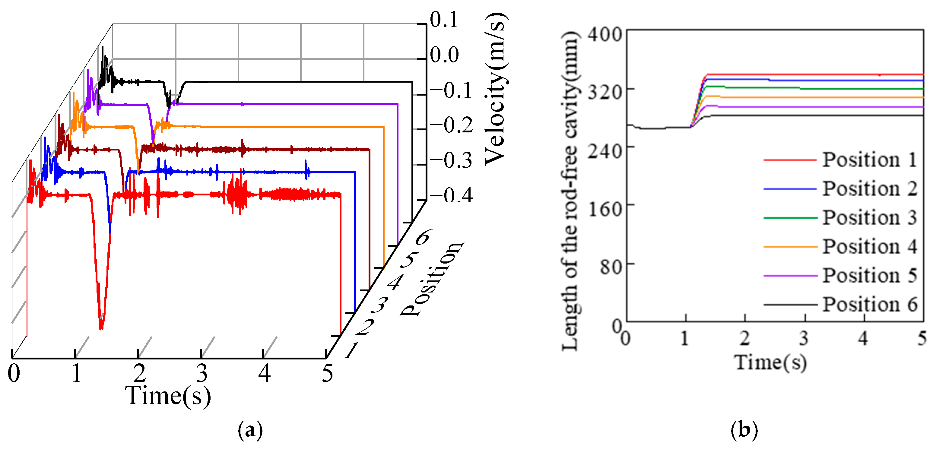
3.3. Effect of the Rotary Position on the Balance Jack System

As one of the key structural components to maintain the hydraulic support attitude, the bearing characteristics of the balance jack are also affected by the rotation position of the roof. Figure 10 shows the balance jack’s piston velocity and length of rod-free cavity curves at different rotary positions. When the hydraulic support is raised to contact the roof, the balance jack piston must be adaptively adjusted to the flatness and the overturning angle of the roof. Therefore, the piston velocity curve fluctuates and then stabilizes gradually [32,33]. Since the model is built to ensure that the top beam and the roof plane are parallel to each other, the overall displacement of the piston is modest during the initial support phase.
During the period of 1~1. 4 s, when the rotary load of the roof acts on the hydraulic support, the top beam rotates with the column socket connected by the top beam and the column as the center point. During this time, the balance jack shows passive elongation. The overall posture of the hydraulic support in space shows a ‘head-up’ trend. With the change in the roof’s rotation speed, the piston’s passive elongation velocity reaches a peak at 1.2 s. Furthermore, the change in the position of the roof rotary modifies the velocity and displacement of the passive tension of the balance jack piston. As the rotation center of the roof moves backward, the peak velocity decreases from −0.38 m/s to −0.1 m/s, and the length of the rod-free cavity decreases from 339 mm to 282 mm. After the roof rotation disappears, the piston speed of the balance jack decreases gradually. As a part of the hydraulic system of the hydraulic support, the dynamic change characteristics of the balance jack system are affected by the column system. It can be found that the balance jack’s piston velocity fluctuates with the continuous overflow of the relief valve in the column. Moreover, the greater the overflow flow in the lower chamber of the column, the more obvious the fluctuation of the speed curve of the balance jack piston.

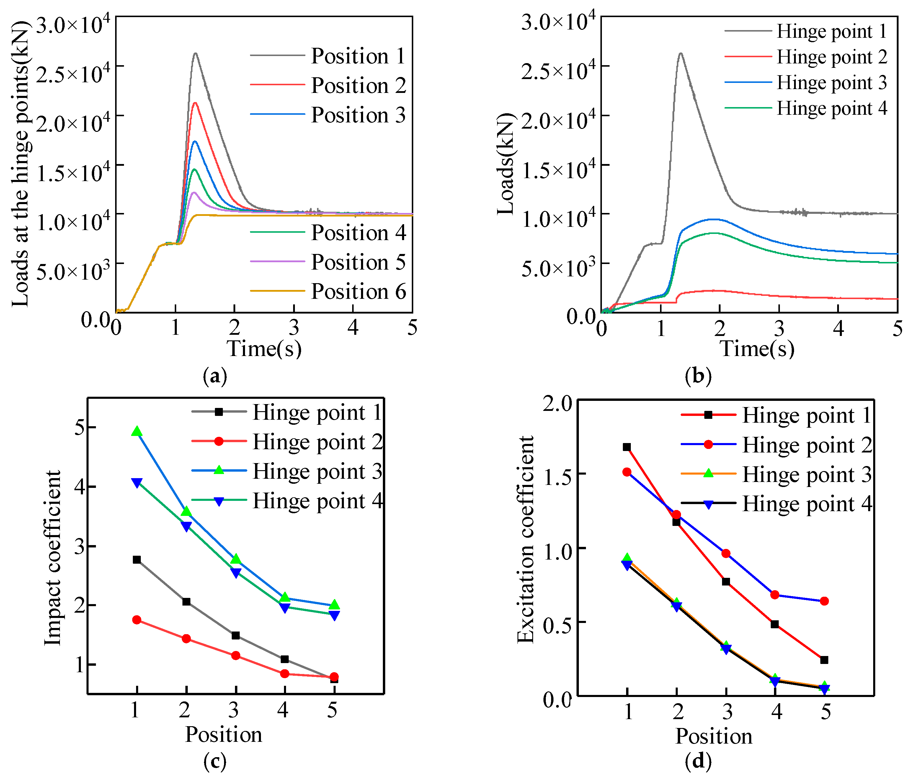
3.4. Effect of the Rotation Position on the Hinge Point Load

During the passive bearing of the hydraulic support, the position of the hinge point is damaged easily, and the load change trend of the hinge point also shows the hydraulic support stress. The impact coefficient and the excitation coefficient are analyzed in the variation trend of the hinge point load at different roof rotary positions. In addition, the sensitivity and adaptability of the hinge points at different locations to the impact loads are evaluated. Since the hydraulic support model is symmetric when set up and there is no eccentric load in the roof loading process, only one-sided hinge points are discussed in the hinge load analysis. For the convenience of description, the hinge points of the top beam and the column, the hinge points of the top beam and the shield beam, the hinge points of the shield beam and the front connecting rod, and the hinge points of the shield beam and the rear connecting rod are defined as hinge points 1, 2, 3, and 4, respectively.
I i = F max F o F o
E i = F max F w F w
As shown in Equations (1) and (2), I i is the impact coefficient of the hinge point load, E i is the excitation coefficient of the hinge point load, F max is the peak load of the hinge point under roof rotation impact, F o is the stable load of the hinge point after the hydraulic support reaches the initial support force, and F w is the new steady-state response load after roof rotation impact.
According to Figure 11a, during the active roof connection of hydraulic support, the load of hinge point 1 is eventually stable at 6990 kN. After 1 s, the overlying roof of the top beam begins to rotate and exerts continuous pressure on the hydraulic support, forcing the load at hinge point 1 to peak at approximately 1.34 s. As the rotation position of the roof changes, the peak load at hinge point 1 is highest at 26,200 kN when the roof is at rotation center 1. When the rotational center moves back to position 6, the peak load at hinge point 1 is the smallest at 9820 kN. Then, with the opening of the relief valve in the lower chamber of the column and the vanishing of the rotational velocity of the roof, the load at hinge point 1 gradually decreases and finally stabilizes at approximately 9712 kN.
According to Figure 11b, when the roof is in rotation position 1, the load performance of the hinge points at different locations of the hydraulic support is different. As the rotation speed of the roof increases, the load of hinge point 1 reaches a peak at 1.34 s, while the loads at the other three hinge point peak at approximately 1.8 s each. The reason is that the stress and deformation of the flexible body components and the load transfer time also need to be considered during the load transfer and movement. Thus, the form of the load curve of the hinge point at different positions is different.
Figure 11c,d shows the load excitation coefficients and impact coefficients for each hinge point when the roof is rotated at position points 1 to 5. It can be seen that the rotational load acting on the hydraulic support is largest when the rotational center of the roof is located at center 1. At this time, the impact coefficient of hinge point 3 is the highest, at 4.42, and the excitation coefficient of hinge point 4 is the smallest, at 0.89. This shows that the hinge point of the shield beam and the front connecting rod is more sensitive to sudden loads, while the hinge point of the shield beam and the rear connecting rod has a stronger adaptive ability to sudden loads. When the rotation position of the roof changes, the feedback values of the excitation coefficient and the impact coefficient of the hinged point load are altered at the same position. However, the changing pattern of the feedback value of the hinge point at different positions is the same. With the backward movement of the rotating position of the roof, the passive bearing capacity of the hydraulic support decreases gradually. Therefore, the peak loads of the hinge points at different positions decrease, and the impact and excitation coefficients of the hinge points at different positions also show a regular decrease.

4. Influence of the Hysteresis Effect of the Relief Valve on the Energy Dissipation of the Hydraulic Support System

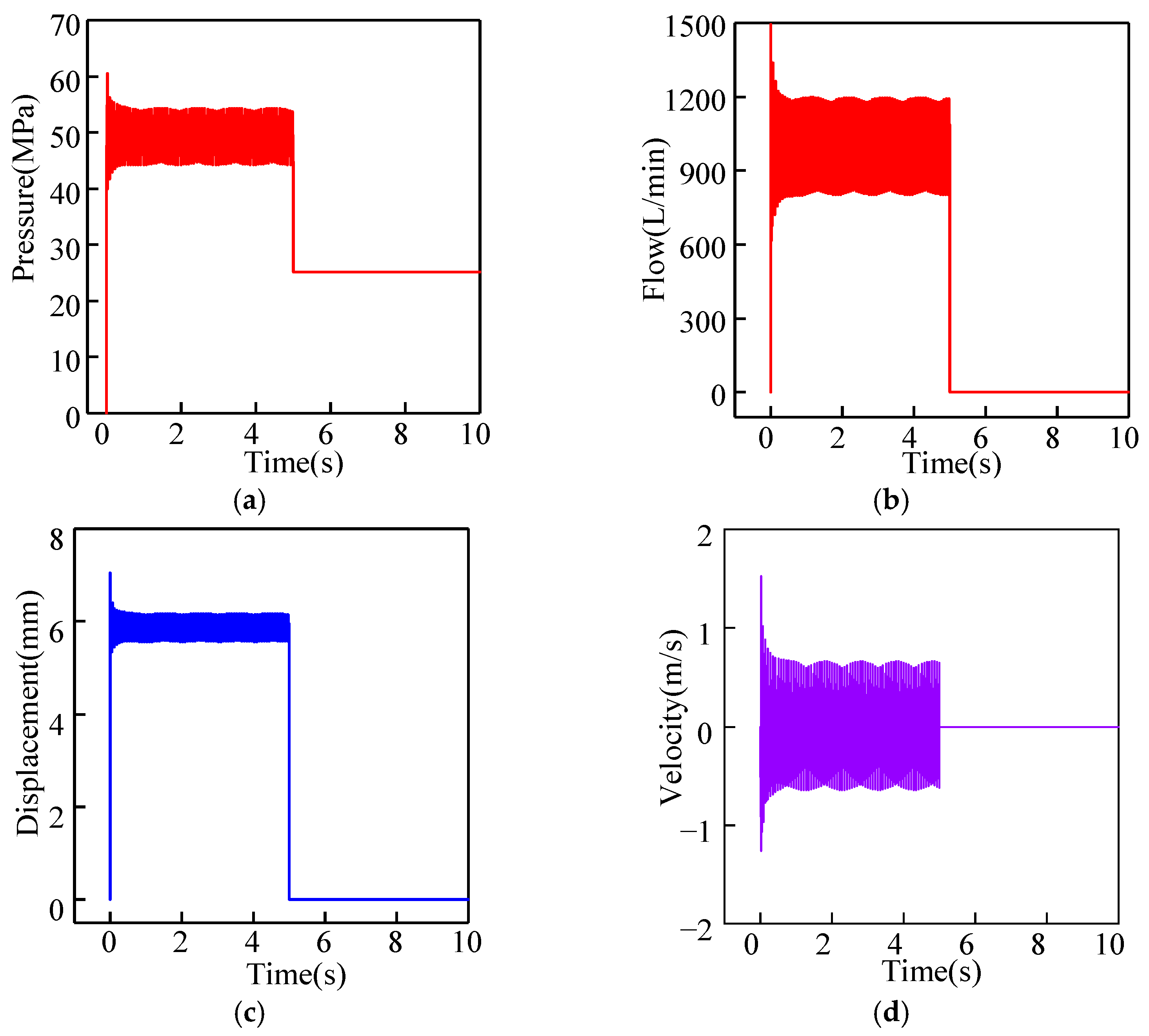
4.1. Analysis of the Dynamic Characteristics of the Relief Valve

In the process of modeling the hydraulic system, the FAD1000/50 relief valve model is used. In the modeling process of the relief valve, the spool diameter of the relief valve is 13 mm, the spool mass is 0.5 Kg, the number of relief holes is 16, the diameter of the relief holes is 3 mm, the spring stiffness is 1000 N/mm, and the preload is 6 mm. Figure 12 shows the simulation results of the relief valve, where 0~5 s is the oil feeding process of the relief valve, and the oil flow rate is 1000 L/min. Figure 12 shows the following results:
(1)
The curves of flow rate, pressure, spool speed, and spool displacement during the opening of the relief valve are continuously fluctuating.
(2)
The maximum pressure of the relief valve is 60 MPa, and the minimum pressure is 40 MPa. The maximum flow rate is 1500 L/min, and the maximum speed of the spool is 1.5 m/s.
(3)
When the relief valve spool is opened continuously, the pressure is stabilized at 50 MPa, the flow rate is stabilized at 1000 L/min, and the spool displacement is stabilized at 6 mm.
The above simulation results show that the type and size of the relief valve meet the design requirements of the two-column hydraulic support.

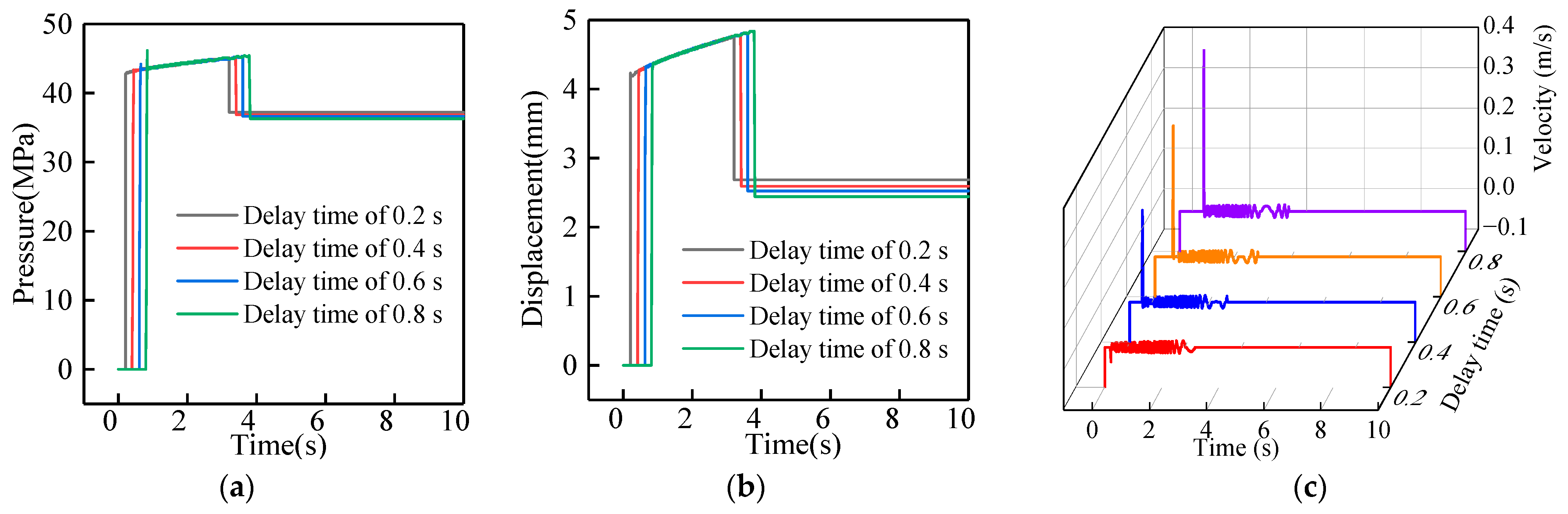
4.2. Response Discrepancy Analysis of the Delayed Opening of the Relief Valve

The hydraulic support is impacted by various alternating loads during operation, and the instantaneous response of the relief valve fails due to the rapid load impact speed. Therefore, in practical applications, there is a delay in the opening of the relief valve. The above analysis of the dynamic characteristics of the relief valve only considers the ideal situation. However, during the coal mining process, the response sensitivity of the relief valve decreases due to numerous factors, such as working conditions, routine maintenance, and oil contamination. In this section, the relief valve is analyzed as a single delayed opening element. The results show the difference in the dynamic response of the relief valve in the delayed opening condition.
According to Figure 13, by delaying the opening time of the relief valve under ideal conditions, it can be seen that with the delay in opening time, the sudden change in pressure at the moment of opening the relief valve is obvious, and the growth of the pressure at the valve port position is proportional to the increase in opening delay time. After the relief valve is opened, the pressure at the valve port position gradually increases, and the increase in the delay time also enhances the maximum value of the pressure at the valve port position. The relief valve spool displacement differences and valve port position pressure are basically the same. By comparing the relief valve spool speed difference, it can be seen that the increase in delayed opening time makes the spool’s instantaneous speed increase by about 800%. Therefore, by analyzing the delayed opening results of the relief valve, it can be seen that the dynamic response results of the relief valve differ as the opening time increases, and the longer the delayed opening time, the more obvious the response difference of the relief valve.
According to the above analysis, if the response time of the relief valve is delayed, its dynamic response appears to be different. In addition, the response sensitivity of the relief valve as part of the hydraulic system also has an impact on the dynamic load bearing of the hydraulic support system. In the system modeling and simulation process, the operating conditions of the relief valve are ideal. However, in the application process, there is an opening delay in the relief valve. The method used in this paper does not explain the details of the dynamic response when the relief valve is delayed in opening, but the effect of the hysteresis effect on the energy unloading of the hydraulic support system can be simulated by adding a delay signal. A follow-up analysis focuses on the difference in impact energy unloading in the hydraulic support system under the hysteresis effect of the relief valve. The load applied by the hydraulic support is provided by the roof rotation at position 1. For the convenience of the narrative, the relief valve delay times used in this paper are integers. The delay opening time of the relief valve is set to t0 = 0 ms, t1 = 100 ms, t2 = 200 ms, and t3 = 300 ms.

4.3. Effect on the Column Hydraulic System

Figure 14a,b shows that the pressure in the lower chamber of the column increases sharply under roof rotation impact. After reaching the opening pressure of the relief valve, the high-pressure oil in the column cannot overflow due to the opening delay of the relief valve. By comparing the pressure curves with different delay times, it can be seen that the delayed opening time of the relief valve increases the peak pressure in the column and extends the pressure stabilization time after the relief valve overflows. The peak pressure in the lower chamber of the column increases continuously, that is, the peaks of the two adjacent pressure curves differed by 4 MPa, 9 MPa, and 10 MPa. By comparing the overflow curve of the lower chamber of the column, it can be seen that the change law of the overflow in the lower chamber of the column is mostly consistent with the change law of the pressure. However, the peak value of the overflow curve does not change significantly for different delay times due to the short rotation impact time of the roof and the influence of the overflow capacity of the relief valve.
Figure 14c shows the velocity curve of the relief valve spool for different delay times. The hysteresis effect of the relief valve also affects the spool velocity. When the delay time of the relief valve is t0, the maximum velocity of the spool movement is 2.16 m/s. When the delay time of the spool is t3, the maximum velocity of the spool movement increases to 15.7 m/s. Although the hysteresis effect of the relief valve improves the response sensitivity of the relief valve spool during the opening, it increases the impact of the spool on the valve seat and critically damages the reliability of the relief valve.

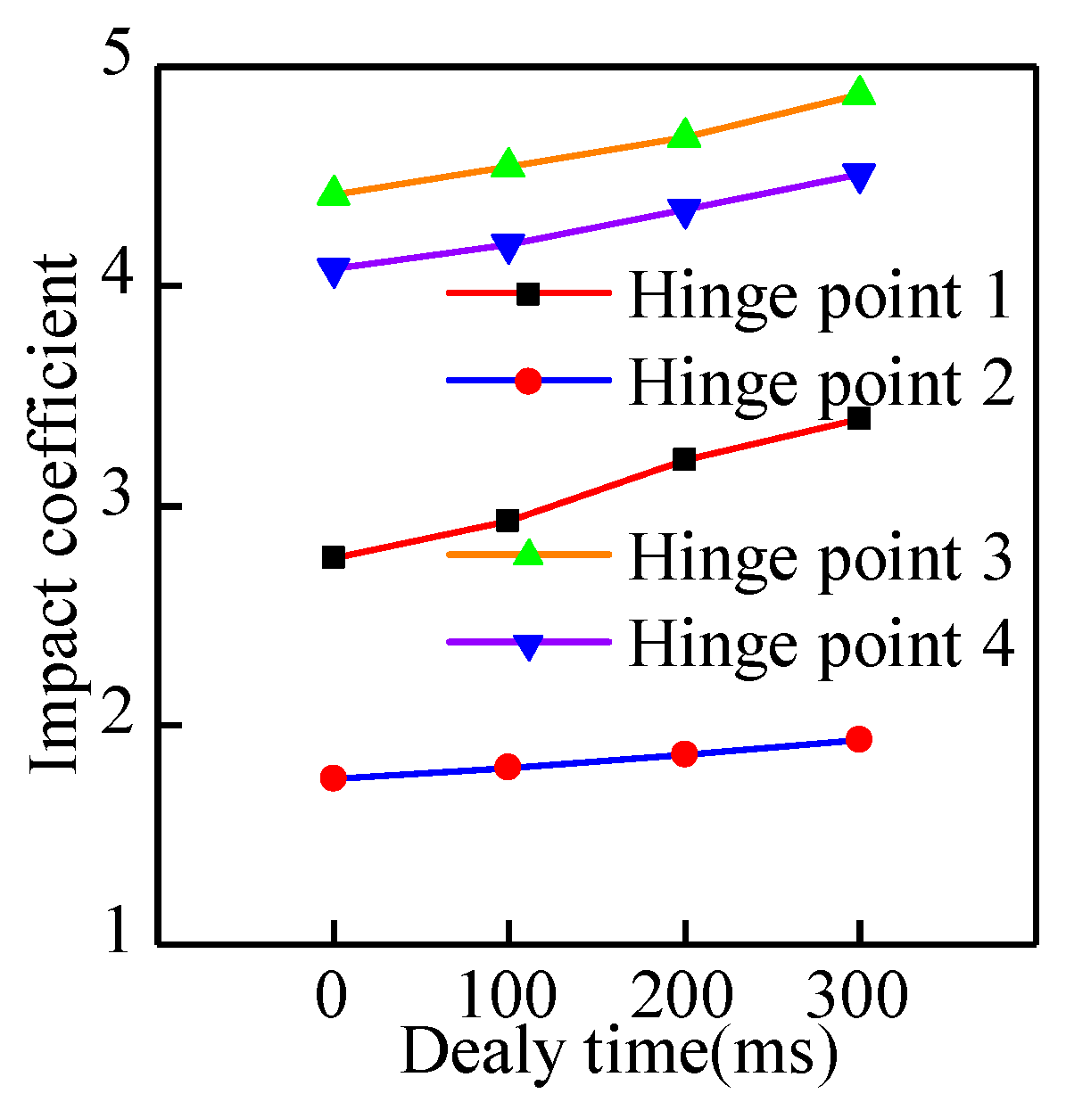
4.4. Effect on the Hinge Point Load

Hydraulic support is a mechanical and hydraulic co-bearing device. The hysteresis effect of the relief valve modifies the hydraulic system’s dynamic response properties and the load transfer law. As the delayed opening time of the relief valve increases, the peak load at hinge point 1 increases from 26,200 kN to 30,667 kN. Then, the load decreases gradually and stabilizes as the relief valve overflows. Due to the delayed effect of the relief valve, the time to reach the stable load at hinge point 1 is delayed correspondingly. According to Figure 15, as the relief valve opening time is extended, the impact coefficient of the hinge points at different locations increases. The trend of the impact coefficient for hinge point 1 is the most pronounced, increasing from 2.79 to 3.39, while the growth rate for hinge point 2 is the smallest, increasing from 1.75 to 1.93. According to the above analysis, the sensitivity of the hinge points to the sudden load at various positions is different for the hysteresis effect of the relief valve. Hinge point 1 is the most sensitive, and hinge point 2 is the least sensitive.

5. Conclusions

In this paper, a mechanical-hydraulic co-simulation platform and a rigid-flexible coupled impact dynamics model of the hydraulic support are established to interpret the characteristics of the hydraulic support under roof rotational impact. The conclusions are as follows:
(1)
Based on the established mechanical-hydraulic co-simulation platform for hydraulic supports, the lifting process of the hydraulic support is simulated. In addition, data on the system flow, pressure, and load at key hinge points during the process are analyzed. The simulation results reproduce perfectly the sequential working characteristics of the double telescopic column of the hydraulic support, indicating that the model is established and the method selection is reasonable and feasible. Compared with single mechanical and hydraulic simulations, the co-simulation process is easier to reproduce intuitively and dynamically, and the simulation results are more reasonable and reliable. The proposed method can support the follow-up study of the impact dynamics of the hydraulic support.
(2)
The load acting on the hydraulic support decreases as the center of rotation of the roof moves backward. Therefore, the response characteristics of the hydraulic system are different. The peak pressure in the lower chamber of the column reduces from 119 MPa to 50 MPa, and the flow also shows the signature of sequential reduction. The relief time of the relief valve is delayed by 1 s. When the roof is located at the center of rotation 1, the passive stretch distance of the balance jack piston is the farthest, and the maximum velocity peak is −0.38 m/s. Affected by the overflow of the relief valve, the fluctuation of the balance jack piston is the most obvious during the stabilization process.
(3)
The hinge points at different locations exhibit different dynamic characteristics as the rotational position of the roof changes. When the roof is located at the center of rotation 1, the maximum peak load of hinge point 1 is 26,200 kN, the impact coefficient of hinge point 3 is the highest (4.42), and the excitation coefficient of hinge point 4 is the lowest (0.89). This indicates that the hinge points of the shield beam and the front connecting rod (hinge point 3) are more sensitive to the abrupt load, while the hinge points of the shield beam and the rear connecting rod (hinge point 4) are more adaptive to the impact load. The peak load, impact coefficient, and excitation coefficient at each hinge point decrease regularly as the roof rotation center point moves toward the back of the top beam.
(4)
The opening time can be extended to simulate the effect of the relief valve’s hysteresis on the system’s energy dissipation. The lower chamber pressure, the valve spool’s instantaneous opening velocity, and the hinge points’ peak load at different positions increase correspondingly with the extension of the opening time. However, the sensitivity of the hinge points at different positions to the hysteresis effect of the relief valve is different. The hinge points of the column and the top beam (hinge point 1) are the most sensitive (impact coefficient increases by 0.63), and the hinge points of the top beam and the shield beam (hinge point 2) are the least sensitive (impact coefficient increases by 0.18).
The results of this study can provide a reference for the structural design and working stability of the hydraulic support. However, this paper does not analyze the influence of pin clearance on the load-bearing process of the hydraulic support. Therefore, the above shortcomings can be introduced in future studies, and a comprehensive comparative evaluation can be carried out.

Author Contributions

Conceptualization, Q.Z.; methodology, C.M.; software, Z.M. and J.W.; validation, C.M. and X.L.; formal analysis, Q.Z.; data curation, C.M.; writing—original draft preparation, C.M.; writing—review and editing, Z.M. and P.X.; investigation, C.M.; resources, C.M. and P.X.; visualization, J.W. and Z.M.; supervision, X.L. and Z.M.; project administration, Z.M.; funding acquisition, Q.Z. and Z.M. All authors have read and agreed to the published version of the manuscript.

Funding

This research was funded by the National Natural Science Foundation of China (51974170, 52104164) and the Natural Science Foundation of Shandong Province (ZR2020QE103).

Data Availability Statement

The data were curated by the authors and are available upon request.

Conflicts of Interest

The authors declare no conflict of interest.

References

  1. Xie, H.P.; Wu, L.X.; Zheng, D.Z. Prediction on the energy consumption and coal demand of China in 2025. J. China Coal Soc. 2019, 44, 1949–1960. [Google Scholar]
  2. Hu, X.P.; Liu, X.H. Mechanism evolution mechanism of active support process of two-leg shield. Coal Sci. Technol. 2022, 1–12. [Google Scholar] [CrossRef]
  3. Wang, G.F.; Pang, Y.H.; Li, M.Z.; Ma, Y.; Liu, X.-H. Hydraulic support and coal wall coupling relationship in ultra large height mining face. J. China Coal Soc. 2017, 42, 518–526. [Google Scholar]
  4. Bu, Q.W.; Tu, M.; Zhang, X.Y.; Zhang, M.Z.; Qing, C. Analysis of Energy Accumulation and Dispersion Evolution of a Thick Hard Roof and Dynamic Load Response of the Hydraulic Support in a Large Space Stope. Front. Earth Sci. 2022, 10, 884361. [Google Scholar] [CrossRef]
  5. Meng, Z.S.; Zhang, J.M.; Xie, Y.Y.; Lu, Z.G.; Zeng, Q.L. Analysis of the Force Response of a Double-Canopy Hydraulic Support under Impact Loads. Int. J. Simul. Model. 2021, 20, 766–777. [Google Scholar] [CrossRef]
  6. Liang, L.C.; Tian, J.J.; Zheng, H. A study on force transmission in a hydraulic support under impact loading on its canopy beam. J. China Coal Soc. 2015, 40, 2522–2527. [Google Scholar]
  7. Zeng, Q.L.; Yang, C.X.; Liu, P. Stress Analysis of Hydraulic Powered Support for Ultra High Mining under Different Roof Pressure. Coal Technol. 2018, 37, 187–189. [Google Scholar]
  8. Zeng, Q.L.; Li, Z.J.; Wan, L.R. Load on bearing and hinge point of hydraulic support under different loading. Coal Eng. 2018, 37, 187–189. [Google Scholar]
  9. Zhao, F.; Qi, Y.H.; Xu, Z.L.; Dou, J.L. Establishment of failure model for shield beam in large mining height hydraulic support and it’s countermeasures research. J. China Coal Soc. 2019, 47, 182–188. [Google Scholar]
  10. Ren, H.W.; Zhang, D.S.; Gong, S.; Zhou, K.; Xi, C.; He, M.; Li, T. Dynamic impact experiment and response characteristics analysis for 1: 2 reduced-scale model of hydraulic support. Int. J. Min. Sci. Technol. 2021, 31, 347–356. [Google Scholar] [CrossRef]
  11. Zeng, X.T.; Meng, G.Y.; Zhou, J.H. Analysis on the pose and dynamic response of hydraulic support under dual impact loads. Int. J. Simul. Model. 2018, 17, 69–80. [Google Scholar] [CrossRef]
  12. Wang, D.L.; Zeng, X.T.; Wang, G.F.; Li, R. Adaptability Analysis of Four-Leg Hydraulic Support with Large Mining Height under Impact Dynamic Load. Shock. Vib. 2022, 2022, 2168871. [Google Scholar] [CrossRef]
  13. Wan, L.; Yu, X.; Ma, D.; Meng, Z.; Zeng, Q.; Qi, G. Dynamic Response Analysis of a Novel Anti-Impact Pressure Balance Jack. Energies 2022, 15, 5236. [Google Scholar] [CrossRef]
  14. Wan, L.R.; Yu, X.H.; Zeng, X.T. Performance analysis of the new balance jack of anti-impact ground pressure hydraulic support. Alex. Eng. J. 2022, 62, 157–167. [Google Scholar] [CrossRef]
  15. Zhao, L.; Han, L.; Zhang, H.; Jin, X.; Wu, T.; Yang, S. Dynamic response of a coal rock caving impact tail beam for hydraulic support. Sci. Rep. 2022, 12, 11535. [Google Scholar] [CrossRef]
  16. Yang, Y.; Zhang, Y.; Zeng, Q.; Wan, L.; Zhang, Q. Simulation Research on Impact Contact Behavior between Coal Gangue Particle and the Hydraulic Support: Contact Response Differences Induced by the Difference in Impacted Location and Impact Material. Materials 2022, 15, 3890. [Google Scholar] [CrossRef]
  17. Zuo, C.; Wei, R.Y.; Wang, H.Y. Analysis of Combined Seal Characteristics of Large Cylinder Diameter Double Expansion Column Piston. Coal Technol. 2022, 41, 171–174. [Google Scholar]
  18. Zeng, Q.L.; Li, Z.J.; Wan, L.R.; Ma, D.; Wang, J. Research on Dynamic Characteristics of Canopy and Column of Hydraulic Support under Impact Load. Energies 2022, 15, 4638. [Google Scholar] [CrossRef]
  19. Liu, Y.A.; Chen, Y.M.; Zhang, K.; Huang, L.S.; Qi, Y.H.; Li, Y.X.; Zhong, D.H.; Wei, X.T.; Zhang, F.J. Analysis of impact characteristics of hydraulic column based on bidirectional fluid-structure coupling. Safe. Coal Mines 2022, 53, 143–147. [Google Scholar] [CrossRef]
  20. Song, Y.N.; Xu, X.C.; Zhang, W.W. Research on dynamic characteristics of two-stage safety valve of hydraulic support under impact loading. J. Ordnance Equip. Eng. 2022, 43, 242–248, 279. [Google Scholar]
  21. Zhao, H.Z.; Wang, X. Experimental Study on Characteristics of Safety Valve of Hydraulic Support under Roof Pressure. Coal Technol. 2022, 41, 222–225. [Google Scholar]
  22. Li, G.Z.; Chi, Z.Y.; Wang, J.H. Analysis and Research on Bearing Characteristics of Hydraulic Support Column for Fully Mechanized Mining Caving Top Coal. Coal Mine Mach. 2020, 41, 41–44. [Google Scholar] [CrossRef]
  23. Cai, Y.; Huang, L.M.; Cui, J.L. Simulation Analysis of Hydraulic System Characteristics of Large Bore Column Control Loop Based on AMESim. Coal Mine Mach. 2020, 41, 177–180. [Google Scholar]
  24. Cao, L.M.; Xu, G.; Su, G.; Cui, J.; Cai, Y.; Cao, H. Design of automatic pressurizing device of hydraulic support initial force. Energy Sci. Eng. 2020, 8, 2868–2877. [Google Scholar] [CrossRef]
  25. Zhang, X.F.; Shao, Y.; Fu, Y.Q. Mechanical and Hydraulic Co-simulation Analysis for Crane Luffing System based on Simcenter 3D. J. Mech. Eng. 2022, 1–8. [Google Scholar]
  26. He, J.; Yang, X.; Zhang, J.; Wang, S.M.; Shen, X.J.; Du, Y.; Li, C. Construction method of wet mix concrete spraying machine co-simulation model based on Automation Studio. Mach. Tool Hydraul. 2022, 50, 168–173. [Google Scholar]
  27. Huang, X.M.; Zhang, T.; Yin, R.Q. Fatigue Life Analysis of Scissor Mechanism Based on Mechanical and Hydraulic Co-simulation. J. Hunan Univ. (Nat. Sci.) 2021, 48, 21–30. [Google Scholar]
  28. Li, J.X.; He, Y. Analysis of Dynamic Characteristic of Rope Adjusting Device Based on ADAMD and AMESim Co-simulation. J. Taiyuan Univ. Technol. 2016, 47, 304–308. [Google Scholar]
  29. Lu, J.S.; Feng, G.B.; Sun, H.G. Co-simulating of Mechanical and Electro-hydraulic System for Virtual Auto-feeding Mechanism Prototyping Technology Based on AMESim/RecurDyn/Simulink. Fire Control Command Control 2016, 41, 188–192. [Google Scholar]
  30. Zhang, S.; Zhang, D.S.; Li, M.Z. Characteristic and Simulation Analysis of Anti-impact Column System in Hydraulic support. Chin. Hydraul. Pneum. 2022, 46, 101–107. [Google Scholar]
  31. Xu, Y.J. Coupling Analysis of Powered Support and Roof in Mining Face. Coal Min. Technol. 2015, 20, 39–42. [Google Scholar]
  32. Sun, Y.F.; Zheng, X.W.; Lin, X.K. Research on Hydraulic Circuit Optimization of Hydraulic Support Balance Jack Based on AMESim. Coal Mine Mach. 2020, 41, 156–158. [Google Scholar] [CrossRef]
  33. Cao, L.M.; Sun, S.J.; Zhang, Z. Optimal design of balance jack control loop of hydraulic support. J. Mine Autom. 2018, 44, 13–18. [Google Scholar]
Figure 1. Mechanical system model.
Energies 16 02052 g001
Figure 2. Hydraulic circuit diagram.
Energies 16 02052 g002
Figure 3. Hydraulic system model: (a) hydraulic operated check valve; (b) stand column; (c) reversing valve; (d) oil tank and pump station; (e) relief valve.
Energies 16 02052 g003
Figure 4. Mechanical-hydraulic co-simulation platform.
Energies 16 02052 g004
Figure 5. (a) The pressure of the lower chamber of the column. (b) The flow of the lower chamber of the column. (c) The length of the rod-free cavity and height of hydraulic support. (d) The length of the rod-free cavity and speed of the balance jack piston. (e) Hinged point load of top beam and shield beam.
Energies 16 02052 g005
Figure 6. Bottom valve position.
Energies 16 02052 g006
Figure 7. Rigid-flexible coupling dynamics model.
Energies 16 02052 g007
Figure 8. (a) Roof rotation position. (b) Velocity of roof rotation.
Energies 16 02052 g008
Figure 9. (a) Pressure of the lower chamber of the column at different rotation positions. (b) Flow of the lower chamber of the column at different rotation positions.
Energies 16 02052 g009
Figure 10. (a) Piston velocity at different rotation positions. (b) Length of the rod-free cavity at different rotation positions.
Energies 16 02052 g010
Figure 11. (a) Hinged point 1 load at different rotation positions. (b) Hinged point loads at different positions. (c) Impact coefficient of each hinge point. (d) Excitation coefficient of each hinge point.
Energies 16 02052 g011
Figure 12. (a) Relief valve pressure. (b) Relief valve flow. (c) Displacement at the spool. (d) Velocity at the spool.
Energies 16 02052 g012
Figure 13. (a) Relief valve pressure. (b) Displacement at the spool. (c) Velocity at the spool.
Energies 16 02052 g013
Figure 14. (a) Pressure of the lower chamber of the column at different delay times. (b) Flow of the lower chamber of the column at different delay times. (c) Velocity of the relief valve spool.
Energies 16 02052 g014
Figure 15. Impact coefficient of each hinge point at different delay times.
Energies 16 02052 g015
Table 1. Hydraulic support structure parameters.
Structural PartsLength/mmWidth/mmWeight/kg
Top beam5200185013,400
Shield beam4600178013,200
Front connecting rod35004602010
Rear connecting rod345015007200
Base plate3900177016,500
Table 2. Technical parameters of two-column hydraulic support.
Technical ParametersNumerical Value
Height/m3.8~8.2
Width/m1.9~2.2
Initial support force/kN16,544
Pumping station pressure/MPa37.5
Working resistance/kN21,000
Table 3. System unit state variables.
VariableVariable CategoryVariable Effect
Input variableyiji1_fLeft column first-stage cylinder force variable
erji1_fLeft column second-stage cylinder force variable
yiji1_1fRight column first-stage cylinder force variable
eiji1_1fRight column second-stage cylinder force variable
pinghengfBalance jack force variable
Output variableyiji1_vLeft column first-stage cylinder velocity variable
yiji1_dLeft column first-stage cylinder displacement variable
eiji1_vLeft column second-stage cylinder velocity variable
eiji1_dLeft column second-stage cylinder displacement variable
yiji1_1vRight column first-stage cylinder velocity variable
yiji1_1dRight column first-stage cylinder displacement variable
eiji1_1vRight column second-stage cylinder velocity variable
eiji1_1dRight column second-stage cylinder displacement variable
pinghengvBalance jack velocity variable
pinghengdBalance jack displacement variable
Table 4. Dimension parameters of the hydraulic cylinder.
Hydraulic CylinderExternal
Diameter/mm
Internal
Diameter/mm
Piston
Stroke/mm
First-stage cylinder5605002110
Second-stage cylinder3803502100
Balance jack cylinder320230800
Disclaimer/Publisher’s Note: The statements, opinions and data contained in all publications are solely those of the individual author(s) and contributor(s) and not of MDPI and/or the editor(s). MDPI and/or the editor(s) disclaim responsibility for any injury to people or property resulting from any ideas, methods, instructions or products referred to in the content.

