

Optimal Insertion of Energy Storage Systems Considering the Economic Dispatch and the Minimization of Energy Not Supplied


Electrical Engineering Career, Universidad Politécnica Salesiana, Quito 170702, Ecuador
*
Author to whom correspondence should be addressed.
Energies 2023, 16(6), 2593; https://doi.org/10.3390/en16062593
Submission received: 5 January 2023
/
Revised: 24 February 2023
/
Accepted: 1 March 2023
/
Published: 9 March 2023
(This article belongs to the Topic Advances in Renewable Energy Technologies and Systems Solutions)
Abstract
:This study presents an optimal insertion model for battery storage systems in the nodes of an electrical transmission network. The proposed model is developed through mixed integer linear programming applied to the calculation of DC power flows, considering restrictions given by the characteristics of the network and by the parameters of the generation units. The proposal’s main objective is to reduce the costs of operation and non-supplied energy produced, due to needing to meet the demand fully or partially. As a case study to evaluate the proposed methodology, the IEEE 24-bar test system is used. In this base case, electrical generators that depend on different primary energy resources are modeled: hydraulic, thermal, photovoltaic, and wind, in addition to potential electrical energy storage systems. These storage systems are assigned as possible analysis scenarios through the proposed optimization technique. The study is carried out in a time horizon of 24 h per day, according to a standard demand curve. With the incorporation of optimally selected storage systems in their capacity and location, it is possible to minimize dependence on the use of fossil fuels. In addition, considerable savings are obtained by reducing generation costs, and the stability of the energy supply is guaranteed. This novel proposal presents a methodology that covers all the variables of this problem, thus guaranteeing an authentic and precise study in terms of optimization. The results obtained highlight and demonstrate the benefits of stability, continuous attention to demand, reduction in dependence on exhaustible and polluting sources, and cost reduction.
1. Introduction
The electricity system has the task of proposing strategies to guarantee its operation and fulfill its mission of covering the current and future energy demand, which is growing rapidly, in line with global economic and technological development. The electricity market has been opened to new efficient technologies being applied, to strengthen electricity production using clean, non-polluting energy sources and energy storage systems. This has encouraged the interest in conducting this research [1].
The capacity of power system equipment must correspond to the energy needs of consumers. This postulate corresponds to the balance between the generation and consumption of electrical energy. It constitutes a challenge for electrical systems in operation in real-time, since the demand is presented as a dynamic hourly consumption with high uncertainty, which threatens the system’s adaptability. Considering this scenario, it is worth highlighting the importance of the new technologies mentioned above, to find alternative sources and means to accumulate energy, since they support the network and makes the system dynamic [2,3].
In this circumstance, the energy supply agents must have an adequate response in their operation and the correct planning for the load supply. Thus, according to [4], the energy produced must exceed by an estimated 20% percent the energy demanded by users, to maintain a balance.
The transfer of electrical energy in most power systems is instantaneous to the load, which increases the level of risk in operation due to the occurrence of faults, causing the loss of continuity in the delivery of the electrical supply [5]. Due to this inefficiency, the dynamic nature of consumption, and the instability of the different energy sources they use, new energy storage strategies are crucial to support the system, because of their reliable structure, security, and economic benefits. They also open the door for other generating units to achieve greater efficiency and decrease losses in energy transport activity [6,7,8]. The ESS (energy storage system) strengthens the operation of the electricity system and provides opportunities for the entry of alternative generations, mostly from renewable energy sources. This way, the system can expand its capacity to meet the demand [9].
Different types of energy storage require schemes that efficiently manage the energy received for its conservation and subsequent delivery, executing optimal and safe work. Various means harness the available resource, such as energy from electrochemical and thermal effects, potential and kinetic energy, or electromagnetic energy [10]. These multiple solutions have their limitations, based on the portion of the energy they can take for storage, the on-site installation of the systems, and the likelihood of continuous operation. These requirements are met mainly by systems of electrochemical origin due to the robust, flexible, and constant development of their technology, especially batteries, with their diverse chemical composition (Pb, Ion, Li, Cd–Ni, S–Na, etc.). Therefore, their applicability to the electrical grid can be highlighted because they are economically profitable, reliable, high-performance, flexible, and high capacity [11,12]. Battery storage is a primary response mechanism in delivering energy to the grid, and its operation is extended for long periods. It is worth highlighting the composition of lead–acid batteries which, due to their robust design, are the most widely implemented large-scale ESS in the electrical system [13].
The transcendental function of energy storage systems, for the present case of batteries, which is the most used EES when operating power systems, is to find a balance between the participating parts of the system, precisely, the productive amount, with several solutions that demand electric service. In addition, their role is to dampen the fluctuations coming from conventional and non-conventional energy sources and provide stability to the network [14]. Therefore, it is relevant to perform an analysis focused on the impact of the penetration of battery storage energy systems, or BESS, to plan and operate the power system and thus be able to access the benefits in the stages of the system, starting with the decrease in losses and readjustment of power flows, which decongests the network and postpones the overall growth of the system, improving voltage levels and reliability [15].
Considering the advantages of the BESS, there have been works such as [16,17] that, using mixed integer programming, have designed an optimal network integrated with BESS. The authors of [17] optimally integrate these systems, with renewable energy-reducing costs as an objective function, as does [18]. Still, this work locates the storage systems based on the dimension of the transformers, and [19] incorporates the BESS into the network but reduces losses.
Based on the literature review, it is possible to define aspects that highlight the contribution of this modeling in comparison with previous work [20,21,22]. This proposal is defined by a mixed integer linear type programming, that considers constraints and technical characteristics of the system and battery storage, DC power flows, and costs (operating, energy not supplied, and storage charge and discharge costs). This study guarantees a complete solution, with consideration of multiple variables. Thus, with the purpose of implementing a methodology that allows the optimal adaptation of the BESS to the electrical system, considering their location, choice, and commissioning in conjunction with the networks, a new generation dispatch model is introduced that, based on technical and economic characteristics, allows locating and sizing the BESS in the network, taking into account constraints, to achieve the objective of minimizing costs, also considering the prices that involve the unserved energy. The model formulation uses linear flow equations and operating cost variables, to include in the storage dispatch by batteries that are optimally attached to the transmission lines, to meet the supply of consumer demand [23].
In this sense, the model proposed for the optimal location of battery storage systems, considering the economic dispatch and the energy not supplied, provides the following improvements in the electrical power system:
- Reduce operating costs due to the state of charge of the batteries as a storage medium.
- Plan possible expansions in the electrical transmission system by redirecting power flows, through the contribution of energy storage systems.
- Increase firmness in delivering non-conventional renewable energy whose resource is intermittent.
- Minimize the income from the dispatch of thermoelectric generation in hours when the energy cost is high, and prioritize the entry of energy storage systems.
- Mitigate the effect of the emission of polluting gases by reducing plants that demand fossil fuel resources, replacing them with clean energy storage and generation through renewable energies.
2. Materials and Methods
Analysis of Battery Storage in the Electric Grid
BESS is a technology of chemical origin, considered the most common and mature technology used for energy storage. The charging process occurs by sensing electrical power and storing it in sets of cells that, by electrochemistry, create a flow of electrons that can return electricity to its output, reversing the process so that it is now a discharge process [24]. The work of these systems makes electrical grids flexible because they optimize fuel requirements, making them less harmful to the environment. They are highly responsive to load changes, which cushions demand fluctuations and give greater openness to the generation’s entry from distributed and renewable resources. Therefore, batteries, in general, are a tool used to improve the quality of energy; they contribute to, or complement, generation and support for transmission and distribution networks [25].
It is possible to detail the most relevant functions of storage in electrical systems [26]:
Generation
Storage is an energy backup used during peak hours, and in cases of contingencies occurring in the generation units, and for black start [27]. BESS is a form of frequency control during critical and normal generation operations and controls the portions of power transfer to other regions.
Transmission Networks
The BESS helps to defer network growth and manage the existing structure concerning congestion, provides stability, and regulates the voltage at the nodes reached by the lines [28,29,30].
Alternative energy sources
Storage is a complement to adhere a more significant portion of clean generation to the electrical system, where batteries configure energy by fast charging and discharging in operation for more extended periods as required. Due to the energy reserve, demand forecasts are accurate at correcting errors in delivering demand through renewable energies. In addition, it generates decongestion and a reduction in oscillations by sources and charge [31].
Other energy services
With storage, it is possible to manage energy, acting in the face of fluctuations, to improve its quality and reliability.
Some technologies have been recognized among the different means of battery storage, because they have been tested and used over the years, for example, lead–acid batteries. Others, such as flux, nickel cadmium, and lithium-ion, are also available but could be improved for their applicability to the energy market. New technologies are being developed daily to improve efficiency, cost, and flexibility of use, such as fuel cells [32]. The storage mechanisms mentioned above are approximately 60 to 95 percent efficient [22], providing significant benefits throughout the energy chain. The main objective of integrating BESS into electricity grids is to contribute to demand supply, as an economically and technically strategic backup supply source.
It should be noted that the costs corresponding to the operation of the generators, transportation activities, and maintenance, up to the point of supply, must be well managed or optimally minimized by the system operators and planners, since the consumers must pay these costs. Therefore, an adequate cost calculation is reflected and evidenced in the tariff of the service, and such service must comply with the due requirements of quality, safety, and reliability. Deficiencies or lack of energy supply in the system result in a cost for energy not supplied that, in competitive markets, must be assumed by the responsible party, or that is justified in the tariff. This concept is related to the energy storage activity because it represents an adequate backup for the electric grid in terms of possible lack of energy supply or unserved energy, which can be reduced by integrating ESS [33,34].
When energy resources are optimized, it is necessary to consider the use of energy that, in specific processes or stages of generation, is produced in excess, and that can be used as a reserve to cover the load directly or indirectly when required, to obtain an energy balance. This can be achieved with storage systems [35].
The disadvantages of BESS are that, their implementation can lead to high investment costs, and their adaptation to the power system requires planning for their optimal integration according to the objectives at technical and economic levels. The choice of the appropriate storage technology depends on the performance indicators of each storage system, because although each technology has the same objective, the design has different particularities depending on its energy origins, such as efficiency, lifetime, self-discharge, and deep discharge rate, capacity, power, and energy density with their specific and nominal values, as well as implementation costs depending on the cost of energy [10,36].
Sizing and optimal location of BESS
The insertion of storage systems is challenging for the electrical grid, so the ideal location and capacity must be considered, to minimize costs and losses and improve voltage and power quality, to avoid contradictory results affecting system stability and cost benefit [14,37].
This first analysis of the BESS involves an optimization problem, because it is not profitable to place these systems in all the busbars of the network, due to their large extension and because their size cannot be exceeded, due to the costs involved in the implementation [38]. To achieve a scenario adapted to the needs of the system, it is necessary to model the power system electrically and economically with storage, to find the proper sizing and management of the facilities, including the possibility of the entry of renewable and distributed generation and its subsequent integration into the electricity market [39]. For this reason, for storage modeling, in this case, the BESS, an electrical model is initially used, where the location and/or energy capacity is calculated based on restrictive operating limits, so that the incorporation of batteries is reliable and safe, and then the financial details are analyzed.
Strategic generation unit with BESS
The economical operation is the next challenge for the inclusion of BESS in the generation dispatch, where the generation units and BESS available to supply electricity to the system demand are configured. The objective of this dispatch problem is to minimize the cost function, considering the cost of the energy not supplied, so the model must consider the equipment restrictions. For the current case, in order to locate the battery storage, capacity limits, power charge, and discharge states, and a selection variable for the BESS input are presented; if the network is considered, flow limits for the lines are included; and for generation, power limits, start and stop ramps, power balances in the nodes, among others, depending on how detailed the study or its objective [40].
The electrical or technical combination with the economic one leads to the application of tools to solve optimization problems that jointly determine the sizing and location of the units, as well as the operation in the electricity sector markets [41]. Optimization algorithms allow different operating strategies to be evaluated, but from the mathematical perspective, for general dispatch that includes BESS along with consideration of the power grid, the modeling of the operating state may be [42]:
- (1)
- Non-linear for the AC flow equations and a mixed integer for the selection and investment decision variables.
- (2)
- Linear by the DC flow equations and mixed integer by the selection and investment decision variables [43].
Methodology for optimal placement of BESS by applying linear load flows.
The electrical and market characteristics corresponding to the system structure must be included in the mathematical formulation of the model to be solved by optimization, to locate the energy storage systems considering power flows.
The programming optimization model, which in this case is mixed integer linear, contemplates objectives and restrictions represented by a set of equations and inequalities that identify parameters and limit the values that the variables involved can have. The characterization that represents the model is detailed below.
Objective function: minimizing total operating costs.
This corresponds to the function to be optimized, of which the minimum value will be found; this objective function is the cost function, considering that it is subject to certain restrictions.
The constitution of the objective cost function for the model is in three segments, as follows:
Generation cost of conventional and non-conventional energy sources.
This cost is determined by the product between the variable cost of production and the hourly power dispatched by this generator.
Cost of energy not delivered or not served.
This cost is calculated as the product between the cost of unsupplied energy regulated in each electrical system and the hourly power that was not supplied.
The cost associated with the charging and discharging process of batteries as storage systems. In the case of charging the storage system, the cost is an incremental value. It is determined by the product between the absorbed hourly power of the system and the cost of the electrical energy consumed in that hour. While in the case of the discharge, it is considered a reduction in the total cost, since the storage system delivers energy on an hourly basis, whose valuation is made with the cost of electrical energy at that moment.
where
| Generation plants | |
| Conventional generation (thermal and hydro) | |
| Non-conventional generation (wind and solar) | |
| Time horizon temporal of analysis | |
| Bar or network connection nodes | |
| The unit cost of generation per generating plant | |
| Power of each generating plant per hour | |
| Unserved energy cost per unit | |
| Load not served per bar in each hour | |
| Battery charging power per bar per hour | |
| Battery discharge power per bar per hour | |
| Valued price of the charge | |
| Valued price of the discharge |
Restrictions
The restrictions that delimit the objective function are related to the generation units, the network, storage, and demand:
Restriction limiting the power delivery capacity of generators.
This restriction guarantees that the generation units’ hourly power to be dispatched is within the established technical limits.
where
| The minimum power of each generator | |
| Maximum power of each generator | |
| Resource occurrence per generator per hour |
Hourly power to be delivered and absorbed per generator.
This corresponds to the start and stop ramp, which is a special feature of thermal and hydraulic generators. Technically, this restriction guarantees that the generator does not make an excessive mechanical effort to increase or reduce its power delivered from one hour to another.
where
| Start ramp for power delivery per generator per hour | |
| Stop ramp from absorbing energy per generator per hour. |
Energy per block usable in a defined period for hydroelectric sources (hydrological model of the system).
This restriction applies to hydroelectric generators, since a dispatch plan considers a limited amount of energy to be used. For this reason, the proposed mathematical formulation guarantees that the energy limit is not exceeded, considering the hourly power dispatched and the plant factor of this type of generator.
where
| One-day analysis period (24 h) | |
| Capacity utilization factor of each generator |
Restriction of active power balance at busbars.
This restriction allows that, for each node of the modeled system, the Kirchhoff node law (LCK) applied to the power flow is fulfilled. For this case, the generation delivered, the unsupplied power, the loading and unloading of the storage system, and the DC power flow are modeled.
where
| corresponding to a respective hour | |
| end bar as a function of time |
The restriction that limits the capacity of power flow that circulates through transmission lines (chargeability).
This inequality guarantees that the DC power flow that circulates through each of the links does not exceed the thermal limit established based on the physical constitution of the conductor.
where
| Active power limit for energy transfer through transmission lines |
The parameter that models the state of charge of the BESS
This allows us to assess the optimal performance of the batteries in a study period, which helps to preserve their useful life. In this context, the state of charge is evaluated considering the initial state of the storage system and its loading and unloading based on the efficiency of these two processes.
where
| BESS state of charge per bar per hour | |
| The initial state of charge of each BESS per bar per hour | |
| BESS charge efficiency | |
| BESS discharge efficiency |
The restriction that limits the state of charge and the charge and discharge power of the BESS.
To select and locate the BESS, it is necessary to include a decision variable within the restrictions that characterize the physical scheme of the BESS. In this context, the state of charge is evaluated, considering the initial state of the storage system and its unloading and charging based on its efficiency in these two processes.
where
| Maximum BESS state of charge | |
| Maximum percentage discharge of the BESS | |
| Maximum percentage charge of the BESS | |
| Minimum percentage of the state of charge | |
| Decision variable for choosing the BESS |
Restriction to determine the number of BESS to be implemented.
This formulation allows a certain number of storage systems to be incorporated into the electrical grid, considering the restrictions imposed by intermittent resources.
where:
| Total BESS units to be incorporated |
Solution process of the optimization problem.
Through the formulation of the model, the costs related to generation, unserved energy, and BESS are minimized, to determine the optimal location of the battery storage systems to be incorporated into the electric grid. The algorithm for the location of the BESS is shown in Table 1.
Considering the proposed pseudocode and the optimization model, the corresponding flow chart is shown in Figure 1.
Study Cases
The formulated modeling, based on mixed integer linear programming, is analyzed and evaluated in two cases applied to the IEEE 24-bus system.
- (1)
- This first study is considered the base case, and it analyzes power dispatch, the charge flows of the lines, and the resulting costs without batteries as a means of storage. The demand–supply is evaluated at the energy level, and from the electrical point of view, the resulting variables are evaluated when demand is at its maximum.
- (2)
- For this study, the optimization model incorporating the BESS is applied, and the power dispatch, the charge flows of the lines, and resulting costs are also analyzed. The energy and electrical level evaluation is similar to the base case, but the effects of storage systems are also considered.
With the approach of these two case studies, it is possible to verify the benefits of the optimal location of storage systems, which are reflected in technical and economic factors.
The applied IEEE model system is presented in Figure 2, and the parameters characterizing the conventional and non-conventional generators are shown in Table 2 and Table 3 [44,45]. The plant factor required by the hydroelectric generators is 0.75, considering medium hydrology; this value generates a total daily energy of 6.3 TWh for these plants [46,47,48].
The application of the model for the first case considers the energy resource as the basis for the power dispatch problem. The occurrence of this resource for non-conventional sources is shown in Table 4 [49,50].
For the modeling of the thermal and hydraulic generation units, the technical and economic characteristics shown in Table 2 have been considered.
The technical and economic characteristics presented in Table 2 have been considered for modeling the thermal and hydraulic generation units.
For modeling the extractable generation units, it is essential to have the percentage amount that the primary resource is available based on the hours of the day. This aspect is detailed in Table 4.
For transmission networks, specific data on busbars and lines are required. These data are shown in Table 5 and Table 6 [44].
3. Results
Based on the formulation and application of the optimization model in the cases presented, and considering the necessary parameters detailed in the previous section, an economic, technical, and energy evaluation can be carried out.
- i.
- Base Case: IEEE 24-bus system without BESS
This initial case energetically evaluates the generation dispatch in 24 h, according to the chosen technologies, as shown in Figure 4. This figure shows that the available generation sources supply the hourly demand, with thermal generation being predominant and, to a lesser extent, the energy produced by the renewable sources of hydraulic, photovoltaic, and wind energy. It should be noted that there is no shortage.
The energy delivery and the respective costs for each technology are shown in detail in Table 10. Based on the results obtained, it can be observed that a portion equivalent to 76% corresponds to the energy produced by thermal sources, and the remaining amount to the rest of the generators. In this case, wind energy contributes 8.6%, that amounts to 4208.36 MWh. In contrast, hydraulic energy corresponds to 12.8%, with an energy of 6300 MWh, and finally, photovoltaic energy contributes 2.6%, whose energy corresponds to 1204.24 MWh.
These dispatch values can be represented through costs in Figure 5, where the most significant economic portion (87%) is associated with thermal generation, and the remainder with other technologies (hydro 6% and solar/wind 7%). It is observed that the total cost at the operational level corresponds to USD 3,230,145.9. By the unit values of energy sales prices by technology, it is concluded that photovoltaic energy is the least expensive, and its value amounts to USD 45,761.12.
For an electrical analysis, the charge values are considered for supply when the demand is maximum. In this way, it is possible to determine the amount of production of the generation units in the dispatch. The results of the dispatch are presented in Table 11. In this period, the demand increases to 2850.00 MW, of which 2242.38 MW are supplied by thermal generation, leaving the rest to extractable energy.
On the other hand, Table 12 shows the flow of power transferred in the links; from this result, it is concluded that none exceeded the established thermal limit, and it is guaranteed that there is no excessive chargeability in the links.
Given the results shown for the maximum demand, Figure 6 shows a single-line diagram of the modeled system, in which the results of both the generation dispatch and the flows through the links have been incorporated, validating that each node complies with the nodal balance associated with Kirchhoff’s node law (LCK).
- ii.
- Optimal location of the BESS in the IEEE 24-bar systems
Firstly, the result of selecting the incorporation of the energy storage systems is shown. For the present formulated model, the characterization of the batteries for their optimal location has been considered. Table 13 indicates the BESS that are selected to be located in the corresponding bars.
With the optimal selection of the BESS, the same evaluation can be performed on the economic, technical, and energy levels. Therefore, it is possible to represent graphically (Figure 6) the generation dispatch for the energy configuration in an hourly period, where it is visualized how the storage influences the energy production. Figure 7 shows the energy delivery by the different production technologies, with thermal generation having the most significant weight in the energy supply, and the influence of the BESS on the dispatch is observed.
Table 14 shows the dispatch results concerning total energy production and per type of generation and storage technology, and includes the respective costs per technology together with storage. Based on the results obtained, it is observed that the portion equivalent to 76.7% corresponds to the energy produced by thermal sources, and the remaining 23.3% (hydro 12.8%) by the rest of the generators, considering that the BESSs deliver a total of 2.5% of the energy to the electric system.
These dispatch values can be represented by the costs shown in Figure 8, where the most significant economic portion (95.1%) is associated with thermal generation, and the remainder to other technologies (14.2%). Still, storage systems stand out, because they represent 1.1% of the total cost when the loading process occurs, while the unloading process generates a considerable saving of 10.4%.
Due to the implementation of storage, it is essential to present the behavior of the variables corresponding to the charging and discharging power, and the state of charge produced during dispatch. These are shown in Figure 9, Figure 10 and Figure 11. In the case of the BESS located at bus 8, it is observed that there is a delivered energy of 498.6 MWh, maintaining the state of charge between a minimum value of 30 MW and a maximum value of 150 MW.
Likewise, for the BESS located in bar 17, it is observed that there is an energy delivered of 383.04 MWh, maintaining the state of charge between a minimum value of 18 MW and a maximum value of 90 MW.
Finally, for the BESS located in bar 19, it is observed that there is an energy delivered of 317.20 MWh, maintaining the state of charge between a minimum value of 20 MW and a maximum value of 100 MW.
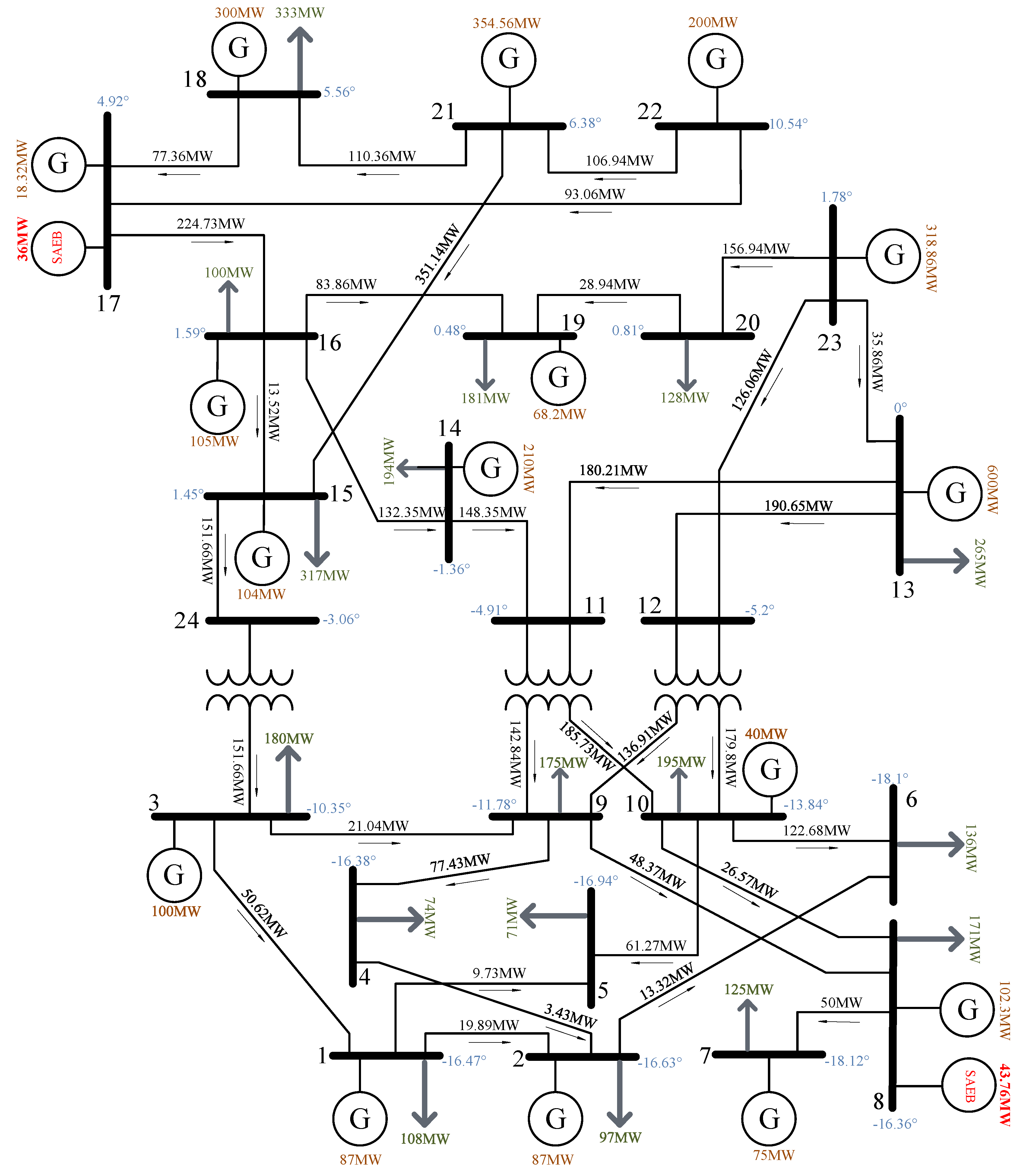
As in the base case, and as a final part of the study, an electrical analysis is performed where the load values are considered for their supply when the demand is maximum. Thus, it is possible to determine the amount of production of the generation units in the dispatch, particularly considering the ESS. The results are shown in Table 15. For the analyzed demand, it is obtained that the BESS located in buses 8 and 17 contributed 79.76 MW. Additionally, the electricity production with the most significant contribution continues to be thermal generation, with a contribution of 2162.62 MW, which is less than the base case but continues to manifest itself.
The power flow through the transmission lines is presented in Table 16. From this result, it can be evidenced that there is a redirection of the power flow, but it is also confirmed that the chargeability level, and the thermal limit for each link, are not exceeded.
Finally, the results obtained and tabulated above are presented in a one-line diagram of the electrical system, shown in the Figure 12.
From the analysis, it is indicated that by including the storage systems, the generation dispatch is affected, with the thermal generation being the one that increases by 260 MWh, since it has enough resource. Under this context, the stored energy, which amounts to 1198.84 MWh, is delivered to the system, causing a cost reduction that results in a daily saving of USD 288,711.54, which amounts to approximately 105 million dollars per year.
In order to qualitatively compare the results obtained here to the works mentioned as being the state of the art, it can be pointed out that the mathematical model developed herein allows establishing of the location of storage systems in electrical networks taking into account the dynamics of the system over time, using DC power flows, which, compared to the study carried out in [15], allows modeling transmission networks and not distribution networks, which allows an advantage for the electricity market at the wholesale level, to undertake technical and economic analysis.
Likewise, the proposed model is analyzing the storage systems individually and not necessarily tied to an intermittent generation, as modeled by the study in [16], thus the model establishes the optimal location of the storage systems to reduce operating costs, without these systems being necessarily tied to the generation sources. When comparing the research in [17] with the proposed model, the advantage of simplifying the complex modeling of the transformers is obtained, without leaving aside the limits of transferability or loadability of the elements.
On the other hand, the research developed corresponds to a mathematical model of classical optimization, and its robustness surpasses the heuristic models, such as the optimization algorithm under uncertainty, described in [18]. Given the above, the model provides advantages and contributions for storage systems to be evaluated and analyzed at the level of transmission networks, and to promote new studies at the market and dispatch level.
Among the main advantages of the proposed study are that the modeling of the network is simplified by the use of DC power flows, in addition to allowing a steady state analysis for each period of time during the 24 h of the day, evaluating the cost of energy not supplied and the optimal location of the storage systems, for which the variables involved are linked in time, i.e., the restrictions are inter-hourly, thus ensuring the operability of the generators and storage systems throughout the analysis period; one of the important advantages, is that the modeling takes into account the variability of renewable resources, which allows interaction with the loading and unloading with the storage systems entering the system, to reduce costs.
Finally, despite the advantages, the model can be adjusted in order to minimize the disadvantages, among them we can point out that the model does not consider the interaction of reactive power flows and its link with voltage levels at the nodes, which is achieved with the incorporation of AC power flows. In addition, thermal generators can be modeled in greater detail, including maximum start and stop times. For its part, the group of generators modeled can be evaluated with power reserve constraints to sudden load variations.
4. Discussion
This paper presents a novel and complete analysis of the optimal insertion of energy storage systems, considering power flows and non-supplied energy. With the optimal injection of electrical energy from the energy storage systems, it was possible to improve the voltage profiles and reduce the network’s chargeability, at the minimum energy dispatch cost. In this study, most energy sources and technologies were included, making the analysis more complete and more complex. The results show the possible energy injection scenarios, and the incidence comparisons, in the variables considered with the power flow.
5. Conclusions
The high penetration of intermittent renewable sources has modified the operational performance of electrical systems. Thus, to compensate for the variation in energy production from these new intermittent sources, energy storage systems have been implemented as a very efficient solution. Energy storage systems, in addition to providing a certain degree of energy stability, guarantee the continuity of electrical service. In addition, the optimal insertion of storage systems allows for minimizing the operating cost, by displacing expensive generation, and also improves voltage levels, by operating as distributed generation.
Considering the above, the proposed mathematical model makes it possible to determine the optimal insertion of storage systems in an electrical power system, by applying DC power flows and evaluating the energy not supplied, in a standard load curve. The proposed model allows for finding the optimal location to install energy storage systems, improving the voltage profile, and significantly reducing operating and generation costs. In addition, the reallocation of the economic dispatch is achieved, displacing expensive generation, and attention to demand is guaranteed as a reliability indicator. From the results obtained in the proposed case study, an economic saving of millions of dollars can be verified, for the concept of insertion with the optimal location of energy storage. In future work, it is proposed to study joint expansion, with distribution networks incorporating distributed generation and storage systems. Research should be done on remuneration mechanisms, considering energy delivery by energy storage systems. The energy reserves for primary control in electrical systems could also be evaluated, considering the stability of the frequency.
Author Contributions
Conceptualization, A.R., A.A.T., L.O. and M.R.; data curation, A.R.; formal analysis, A.R., A.A.T. and L.O.; funding acquisition, A.A.T.; investigation, A.R. and A.A.T.; methodology, A.R. and A.A.T.; project administration, A.R., A.A.T., L.O. and M.R.; resources, A.R. and A.A.T.; software, A.R. and A.A.T.; supervision, A.R. and A.A.T.; validation, A.R., A.A.T., L.O. and M.R.; visualization, A.R. and A.A.T.; writing—original draft, A.R. and A.A.T.; writing—review and editing, A.R., A.A.T., L.O. and M.R. All authors have read and agreed to the published version of the manuscript.
Funding
This research received no external funding.
Conflicts of Interest
The authors declare no conflict of interest.
References
- Liu, Z.; Liu, Y.; Xu, H.; Liao, S.; Zhu, K.; Jiang, X. Dynamic economic dispatch of power system based on DDPG algorithm. Energy Rep. 2022, 8, 1122–1129. [Google Scholar] [CrossRef]
- Téllez, A.A.; Ortiz, L.; Ruiz, M.; Narayanan, K.; Varela, S. Optimal location of reclosers in electrical distribution systems considering multicriteria decision through the generation of scenarios using the Montecarlo method. In Proceedings of the 2015 IEEE 6th Latin American Symposium on Circuits & Systems (LASCAS 2015), Montevideo, Uruguay, 24–27 February 2015. [Google Scholar] [CrossRef]
- Abdin, A.F.; Zio, E. Optimal Planning of Electric Power Systems. Springer Optim. Appl. 2019, 152, 53–65. [Google Scholar]
- Yang, Y.; Wu, W.; Wang, B. Adjustable Robust Economic Dispatch: Case Study on its Application and Evaluation in Power System. In Proceedings of the 2020 IEEE 4th Conference on Energy Internet and Energy System Integration (EI2), Wuhan, China, 30 October–1 November 2020; pp. 1439–1443. [Google Scholar] [CrossRef]
- Ubertalli, J.; Littler, T. Chapter 4Proven energy storage system applications for power systems stability and transition issues. In Predictive Modelling for Energy Management and Power Systems Engineering; Deo, R., Samui, P., Roy, S.S., Eds.; Elsevier: Amsterdam, The Netherlands, 2021; pp. 85–114. [Google Scholar] [CrossRef]
- Castillo, F.; Aguila, A.; Gonzalez, J. Analysis of Stability of Tension and Losses of Electric Power in Distribution Networks with Distributed Generation. IEEE Lat. Am. Trans. 2016, 14, 4491–4498. [Google Scholar] [CrossRef]
- Tellez, A.A.; Galarza, D.F.C.; Matos, L.O. Analysis of power losses in the asymmetric construction of electric distribution systems. IEEE Lat. Am. Trans. 2015, 13, 2190–2194. [Google Scholar] [CrossRef]
- Aguila, A.; Wilson, J. Technical and Economic Assessment of the Implementation of Measures for Reducing Energy Losses in Distribution Systems. IOP Conf. Series: Earth Environ. Sci. 2017, 73, 12018. [Google Scholar] [CrossRef] [Green Version]
- López-Grajales, A.M.; González-Sanchez, J.W.; Cardona-Restrepo, H.A.; Isaac-Millan, I.A.; López-Jiménez, G.J.; Vasco-Echeverri, O.H. Economy, financial, and regulatory method for the integration of electrical energy storage in a power network. J. Energy Storage 2023, 58, 106433. [Google Scholar] [CrossRef]
- Zhang, Z.; Ding, T.; Zhou, Q.; Sun, Y.; Qu, M.; Zeng, Z.; Ju, Y.; Li, L.; Wang, K.; Chi, F. A review of technologies and applications on versatile energy storage systems. Renew. Sustain. Energy Rev. 2021, 148, 111263. [Google Scholar] [CrossRef]
- Koohi-Fayegh, S.; Rosen, M.A. A review of energy storage types, applications and recent developments. J. Energy Storage 2020, 27, 101047. [Google Scholar] [CrossRef]
- Mitali, J.; Dhinakaran, S.; Mohamad, A. Energy storage systems: A review. Energy Storage Sav. 2022, 1, 166–216. [Google Scholar] [CrossRef]
- Wang, J.; Deng, H.; Qi, X. Cost-based site and capacity optimization of multi-energy storage system in the regional integrated energy networks. Energy 2022, 261, 125240. [Google Scholar] [CrossRef]
- Garrido, C.; Téllez, A.A.; Ortiz, L. Linear Voltage Stability Indicator (LVSI) for Optimal Placement of SVC Devices to Improve the Voltage Stability Margin in Transmission Systems. Electronics 2022, 12, 43. [Google Scholar] [CrossRef]
- Razzhivin, I.; Suvorov, A.; Ufa, R.; Andreev, M.; Askarov, A. The energy storage mathematical models for simulation and comprehensive analysis of power system dynamics: A review. Part II. Int. J. Hydrogen Energy 2023, 48, 6034–6055. [Google Scholar] [CrossRef]
- Valencia, A.; Hincapie, R.A.; Gallego, R.A. Optimal location, selection, and operation of battery energy storage systems and renewable distributed generation in medium–low voltage distribution networks. J. Energy Storage 2020, 34, 102158. [Google Scholar] [CrossRef]
- Sok, V.; Tayjasanant, T. Determination of optimal siting and sizing of energy storage system in PV-connected distribution systems considering minimum energy losses. In Proceedings of the 2017 14th International Conference on Electrical Engineering/Electronics, Computer, Telecommunications and Information Technology (ECTI-CON), Phuket, Thailand, 27–30 June 2017; pp. 451–454. [Google Scholar]
- Saha, S.; Saini, G.; Mishra, S.; Chauhan, A.; Upadhyay, S. A comprehensive review of techno-socio-enviro-economic parameters, storage technologies, sizing methods and control management for integrated renewable energy system. Sustain. Energy Technol. Assessments 2022, 54, 102849. [Google Scholar] [CrossRef]
- Alsharif, H.; Jalili, M.; Hasan, K.N. Power system frequency stability using optimal sizing and placement of Battery Energy Storage System under uncertainty. J. Energy Storage 2022, 50, 104610. [Google Scholar] [CrossRef]
- Furtado, G.C.D.A.; Mesquita, A.L.A.; Morabito, A.; Hendrick, P.; Hunt, J.D. Using hydropower waterway locks for energy storage and renewable energies integration. Appl. Energy 2020, 275, 115361. [Google Scholar] [CrossRef]
- de Luis-Ruiz, J.M.; Carcedo-Haya, J.; Pereda-García, R.; Castro-Alonso, P.; Pérez-Álvarez, R. Optimal location of hydraulic energy storage using geographic information systems and multi-criteria analysis. J. Energy Storage 2022, 49, 104159. [Google Scholar] [CrossRef]
- Nikolaou, T.; Stavrakakis, G.S.; Tsamoudalis, K. Modeling and Optimal Dimensioning of a Pumped Hydro Energy Storage System for the Exploitation of the Rejected Wind Energy in the Non-Interconnected Electrical Power System of the Crete Island, Greece. Energies 2020, 13, 2705. [Google Scholar] [CrossRef]
- Wali, S.B.; Hannan, M.A.; Reza, M.S.; Ker, P.J.; Begum, R.A.; Rahman, M.S.A.; Mansor, M. Battery storage systems integrated renewable energy sources: A biblio metric analysis towards future directions. J. Energy Storage 2021, 35, 102296. [Google Scholar] [CrossRef]
- Jafari, M.; Korpås, M.; Botterud, A. Power system decarbonization: Impacts of energy storage duration and interannual renewables variability. Renew. Energy 2020, 156, 1171–1185. [Google Scholar] [CrossRef]
- Challenge, E.S.G. Energy Storage Market Report; US Department of Energy: Washington, DC, USA, 2020. [Google Scholar]
- Hannan, M.; Wali, S.; Ker, P.; Rahman, M.A.; Mansor, M.; Ramachandaramurthy, V.; Muttaqi, K.; Mahlia, T.; Dong, Z. Battery energy-storage system: A review of technologies, optimization objectives, constraints, approaches, and outstanding issues. J. Energy Storage 2021, 42, 103023. [Google Scholar] [CrossRef]
- Lai, C.S.; Locatelli, G. Economic and financial appraisal of novel large-scale energy storage technologies. Energy 2021, 214, 118954. [Google Scholar] [CrossRef]
- Téllez, A.; López, G.; Isaac, I.; González, J. Optimal reactive power compensation in electrical distribution systems with distributed resources. Review. Heliyon 2018, 4, e00746. [Google Scholar] [CrossRef] [PubMed] [Green Version]
- Téllez, A.A. Optimización Multicriterio de Flujos de Potencia Reactiva en Sistemas Eléctricos de Distribución. Tesis de Doctorado. 15 June 2021, p. 105. Available online: http://hdl.handle.net/20.500.11912/8699 (accessed on 1 June 2021).
- Águila, A.; Ortiz, L.; Orizondo, R.; López, G. Optimal location and dimensioning of capacitors in microgrids using a multicriteria decision algorithm. Heliyon 2021, 7, e08061. [Google Scholar] [CrossRef]
- Olabi, A.; Onumaegbu, C.; Wilberforce, T.; Ramadan, M.; Abdelkareem, M.A.; Alami, A.H.A. Critical review of energy storage systems. Energy 2021, 214, 118987. [Google Scholar] [CrossRef]
- Torabi, F.; Ahmadi, P. Chapter 1—Battery technologies. In Simulation of Battery Systems; Torabi, F., Ahmadi, P., Eds.; Academic Press: Cambridge, MA, USA, 2020; pp. 1–54. [Google Scholar]
- Ckardt, G.S.; Pistonesi, H. A Possibilistic Model to Sstimate the Intrinsic Cost of Non Supply Energy in Electric Distribution Systems. Argentina. 2012. Available online: http://www.scielo.org.co/scielo.php?pid=S0012-73532010000200026&script=sci_abstract&tlng=en (accessed on 1 June 2021).
- RMER and CRIE. Metodología Para el Cálculo del Costo de Energía No Suministrada—CRIE. 2013. Available online: https://crie.org.gt/wp/wp-content/uploads/2018/01/METODOLOG%C3%8DA-PARA-EL-C%C3%81LCULO-DEL-COSTO-DE-LA-ENERG%C3%8DA-NO-SUMINISTRADA.pdf (accessed on 1 June 2021).
- Hamidan, M.-A.; Borousan, F. Optimal planning of distributed generation and battery energy storage systems simultaneously in distribution networks for loss reduction and reliability improvement. J. Energy Storage 2021, 46, 103844. [Google Scholar] [CrossRef]
- Nie, B.; Palacios, A.; Zou, B.; Liu, J.; Zhang, T.; Li, Y. Review on phase change materials for cold thermal energy storage applications. Renew. Sustain. Energy Rev. 2020, 134, 110340. [Google Scholar] [CrossRef]
- Kim, R.-K.; Glick, M.B.; Olson, K.R.; Kim, Y.-S. MILP-PSO Combined Optimization Algorithm for an Islanded Microgrid Scheduling with Detailed Battery ESS Efficiency Model and Policy Considerations. Energies 2020, 13, 1898. [Google Scholar] [CrossRef] [Green Version]
- Yang, Y.; Bremner, S.; Menictas, C.; Kay, M. Modelling and optimal energy management for battery energy storage systems in renewable energy systems: A review. Renew. Sustain. Energy Rev. 2022, 167, 112671. [Google Scholar] [CrossRef]
- Lipu, M.H.; Ansari, S.; Miah, S.; Hasan, K.; Meraj, S.T.; Faisal, M.; Jamal, T.; Ali, S.H.; Hussain, A.; Muttaqi, K.M.; et al. A review of controllers and optimizations based scheduling operation for battery energy storage system towards decarbonization in microgrid: Challenges and future directions. J. Clean. Prod. 2022, 360, 132188. [Google Scholar] [CrossRef]
- Kantor, I.; Robineau, J.-L.; Bütün, H.; Marechal, F. A mixed-integer linear programming formulation for optimizing multi-scale material and energy integration. Front. Energy Res. 2020, 8, 49. [Google Scholar] [CrossRef] [Green Version]
- Varetsky, Y.; Konoval, V.; Seheda, M. Modeling Power Flow within a Microgrid for Energy Storage Sizing. In Proceedings of the 2020 IEEE 7th International Conference on Energy Smart Systems (ESS), Kyiv, Ukraine, 12–14 May 2020; pp. 150–153. [Google Scholar] [CrossRef]
- Shah, C.; Wies, R. Algorithms for Optimal Power Flow in Isolated Distribution Networks Using Different Battery Energy Storage Models. In Proceedings of the 2020 IEEE Power & Energy Society Innovative Smart Grid Technologies Conference (ISGT), Washington, DC, USA, 17–20 February 2020; pp. 1–5. [Google Scholar] [CrossRef]
- Mühlbauer, M.; Bohlen, O.; Danzer, M.A. Analysis of power flow control strategies in heterogeneous battery energy storage systems. J. Energy Storage 2020, 30, 101415. [Google Scholar] [CrossRef]
- Ordoudis, C.; Pinson, P.; Morales, J.; Zugno, M. An Updated Version of the IEEE RTS 24-Bus System for Electricity Market and Power System Operation Studie; Technical University of Denmark: Kongens Lyngby, Denmark, 2016; Volume 13. [Google Scholar]
- van der Veen, R.A.; Hakvoort, R.A. The electricity balancing market: Exploring the design challenge. Util. Policy 2016, 43, 186–194. [Google Scholar] [CrossRef] [Green Version]
- Hosseinzadeh, A.; Zhou, J.L.; Li, X.; Afsari, M.; Altaee, A. Techno-economic and environmental impact assessment of hydrogen production processes using bio-waste as renewable energy resource. Renew. Sustain. Energy Rev. 2022, 156. [Google Scholar] [CrossRef]
- El-Enien, A.S.A. Efficient electricity markets. In Proceedings of the 2013 IEEE Grenoble Conference, Grenoble, France, 18–22 March 2013; pp. 1–6. [Google Scholar]
- IRENA. Renewable Power Generation Costs in 2020; International Energy Agency: Abu Dhabi, United Arab Emirates, 2021; [Online]; Available online: https://www.irena.org (accessed on 1 June 2021).
- MERNNR. “Plan Maestro de Electricidad 2019-2027,” Ministerio de Energía y Recursos No Renovables. 2019, p. 390, [Online]. Available online: https://www.recursosyenergia.gob.ec/plan-maestro-de-electricidad/ (accessed on 1 June 2021).
- U.S Energy Information Administration. “U.S. Energy Information Administration, Annual Energy Outlook 2021 (AEO2021),” EIA. Annual Energy Outlook 2021 (AEO2021). 2021; Volume 2021. Available online: https://www.eia.gov/outlooks/aeo/tables_side.php (accessed on 1 June 2021).
- Mahlia, T.; Saktisahdan, T.; Jannifar, A.; Hasan, M.; Matseelar, H. A review of available methods and development on energy storage; technology update. Renew. Sustain. Energy Rev. 2014, 33, 532–545. [Google Scholar] [CrossRef]
- Ibrahim, H.; Ilinca, A.; Perron, J. Energy storage systems—Characteristics and comparisons. Renew. Sustain. Energy Rev. 2008, 12, 1221–1250. [Google Scholar] [CrossRef]
Figure 1.
Flowchart.

Figure 2.
IEEE 24-bar diagram [44].
Figure 2.
IEEE 24-bar diagram [44].
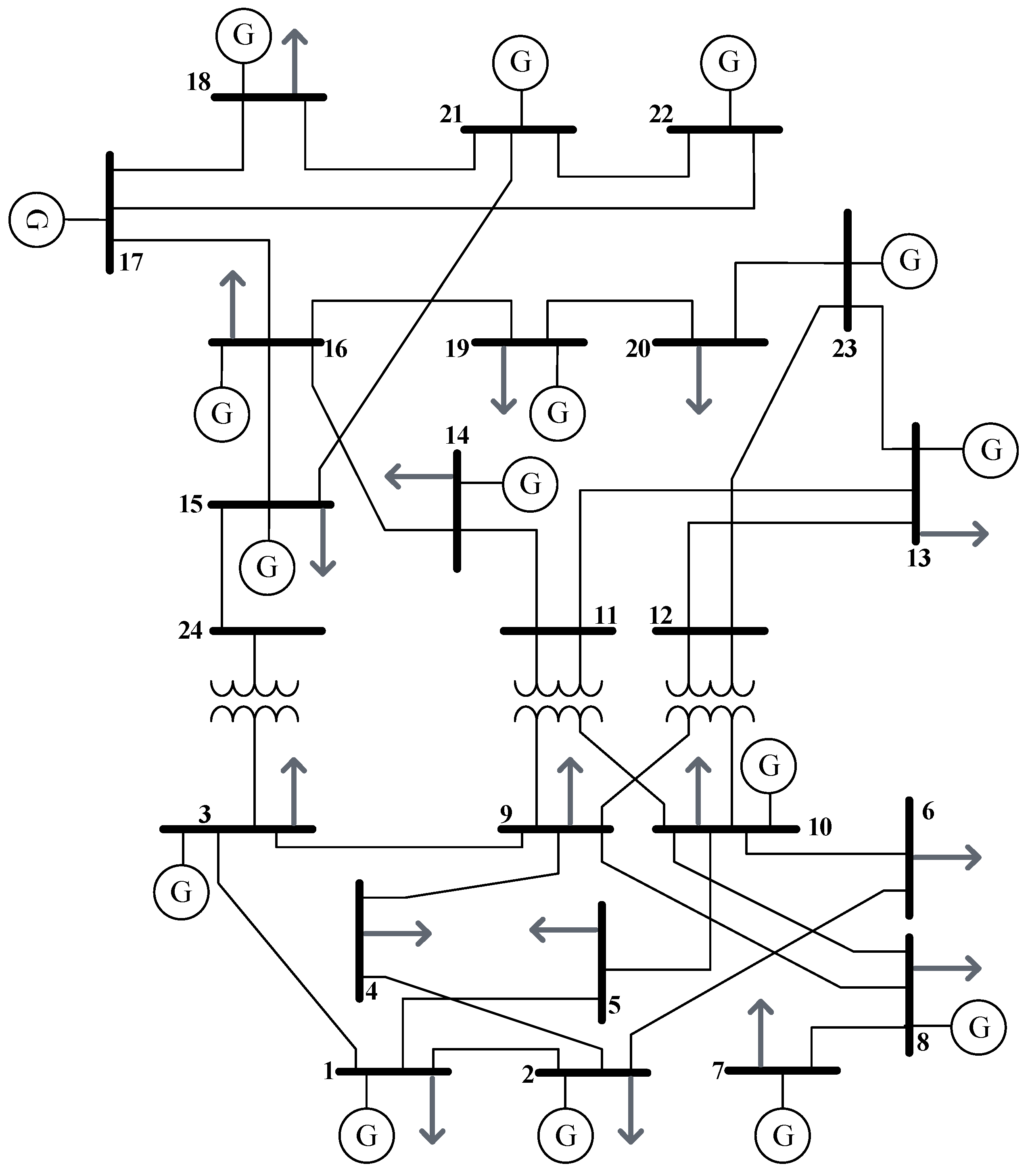
Figure 3.
The accumulated curve of hourly charge.
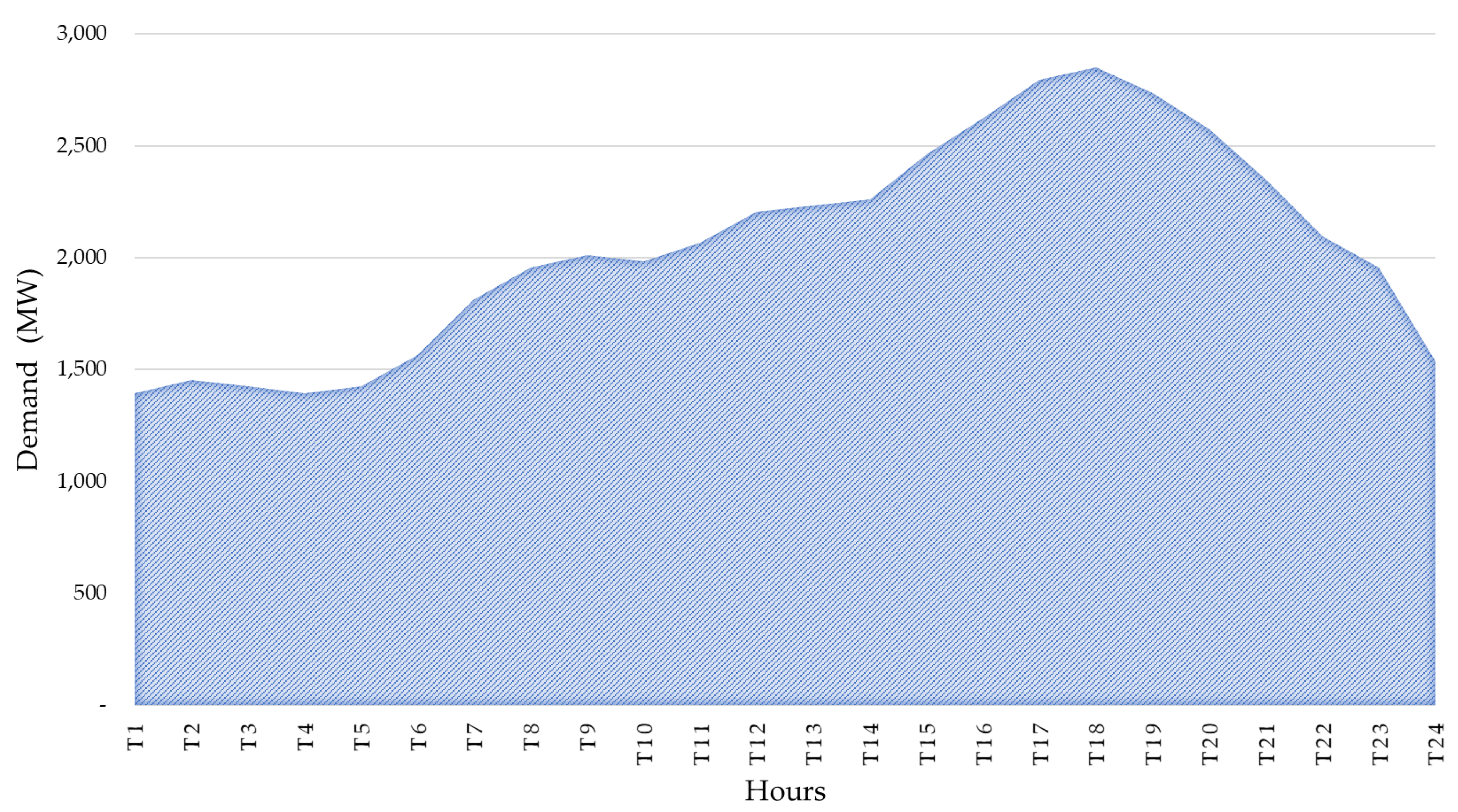
Figure 4.
Time dispatch with the generation technologies involved.
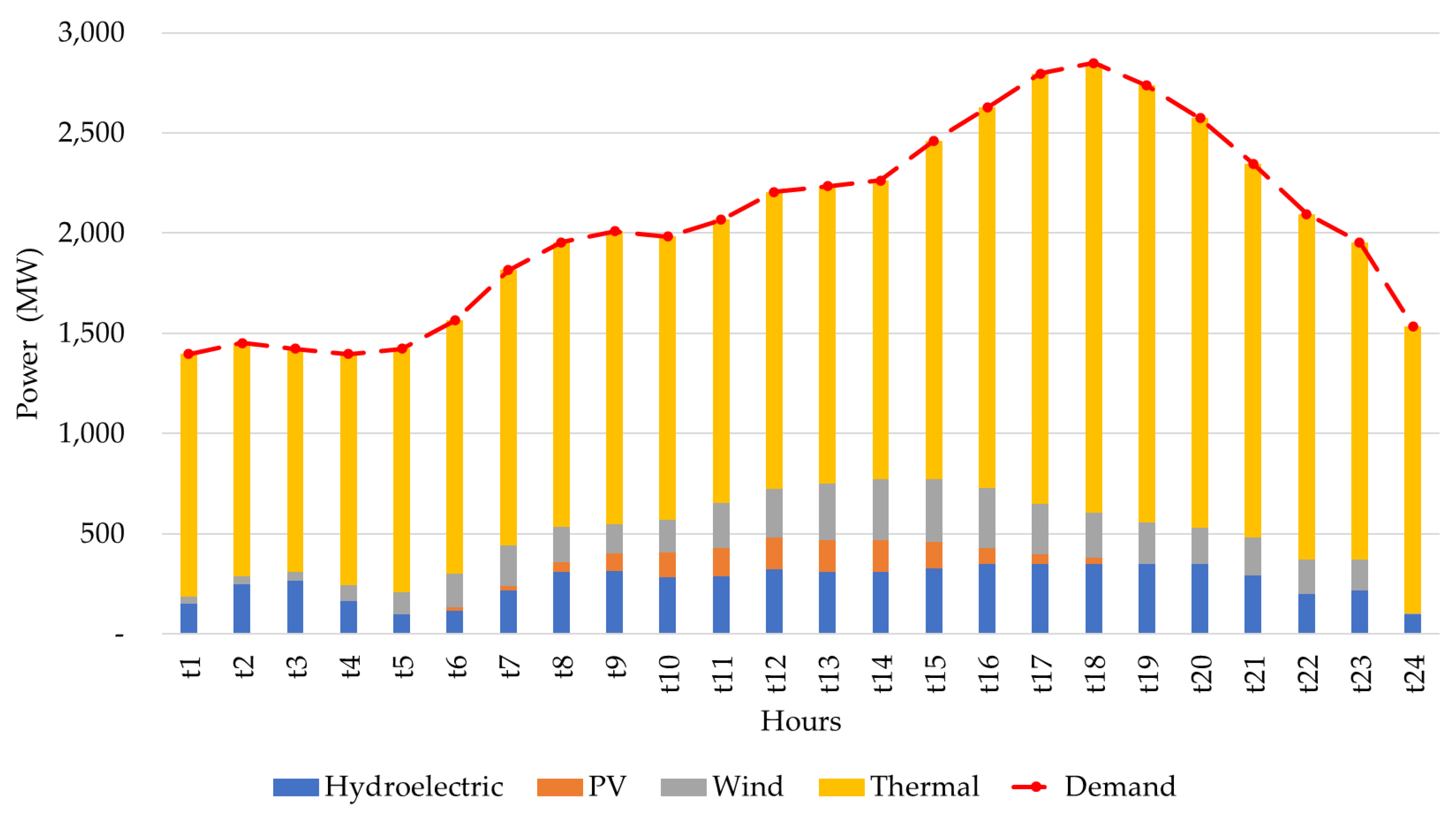
Figure 5.
Dispatch costs segmented by generation type.
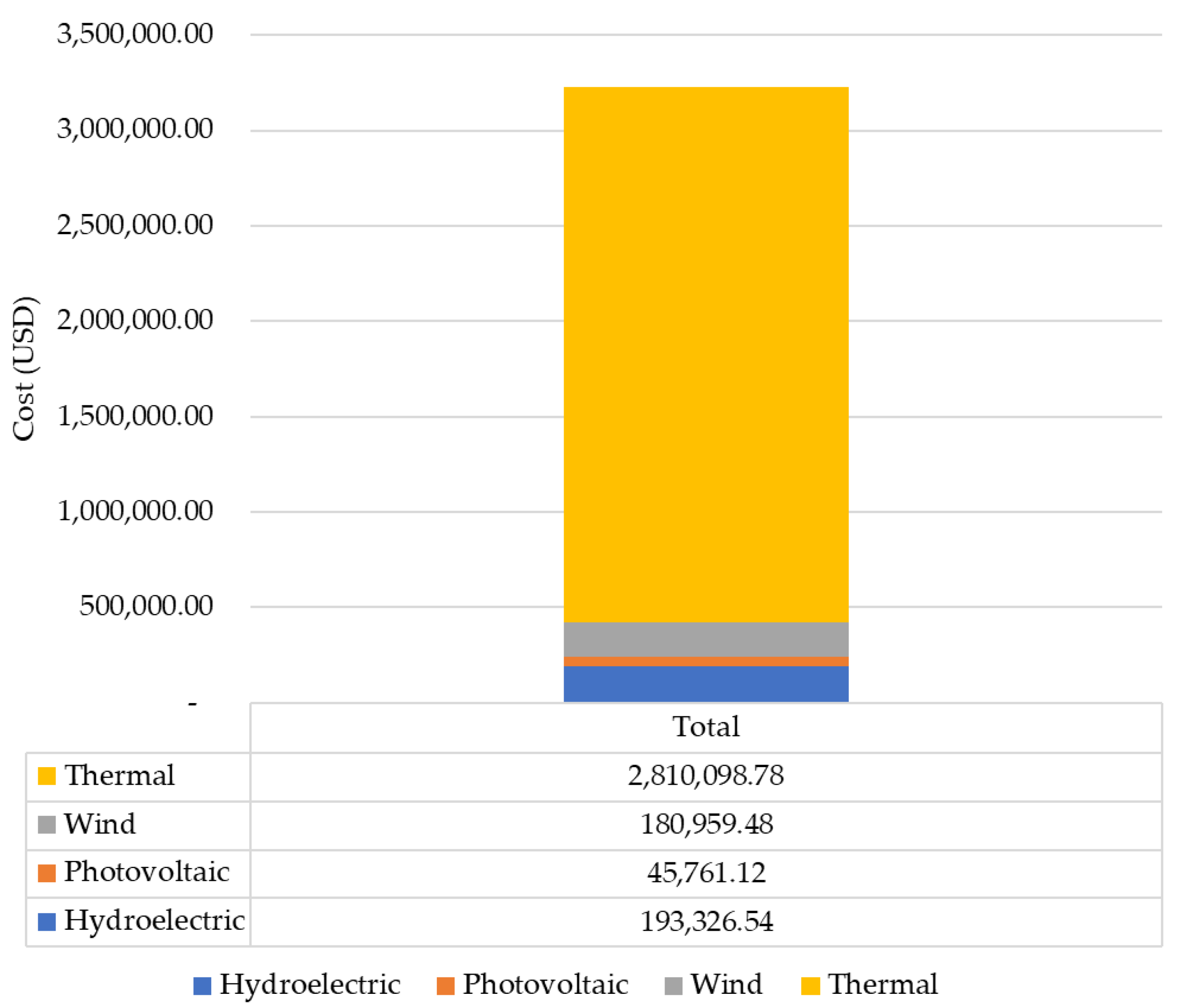
Figure 6.
The single-line diagram at maximum demand for the base study.
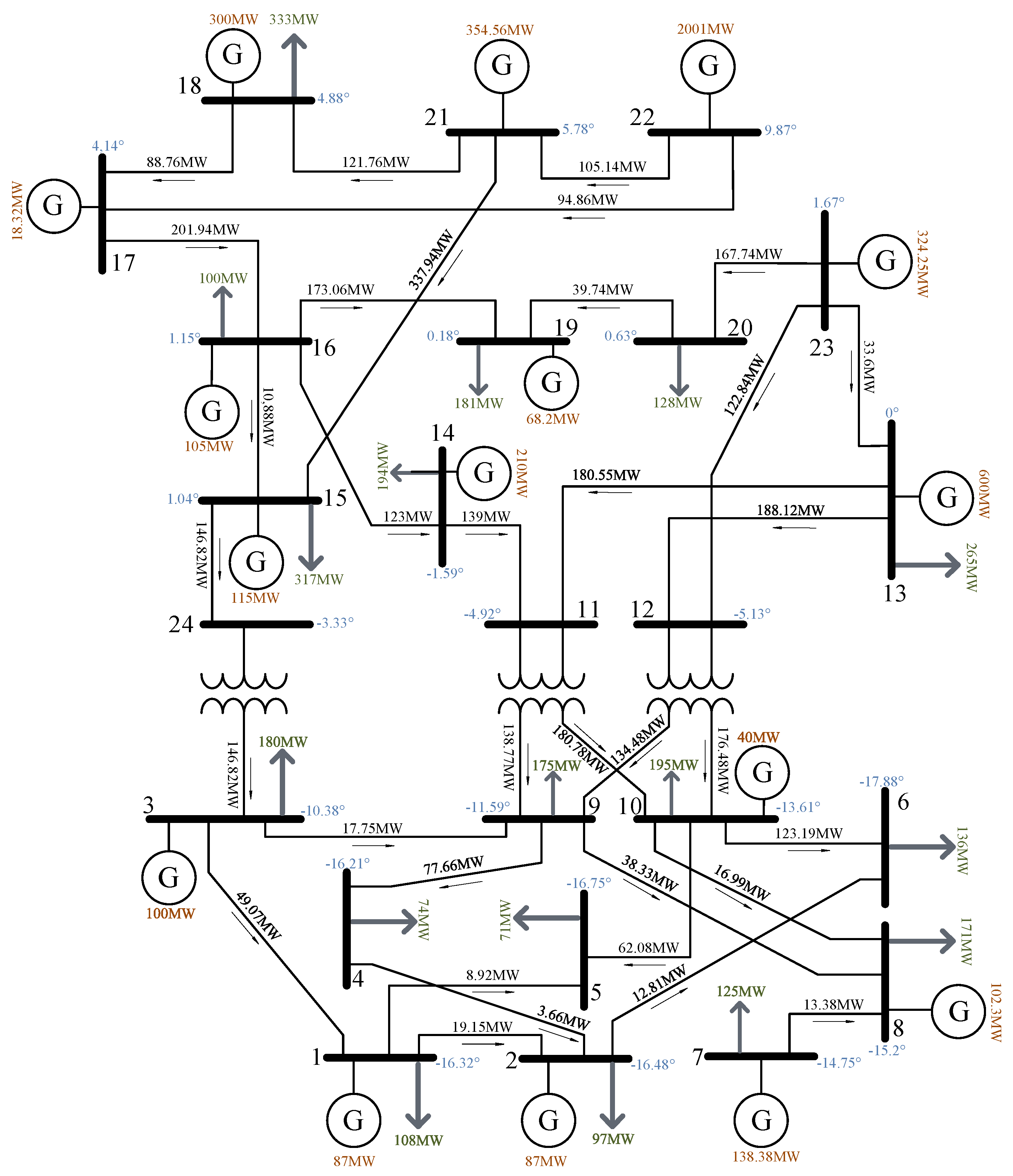
Figure 7.
Hourly dispatch based on generation technologies and battery storage systems.
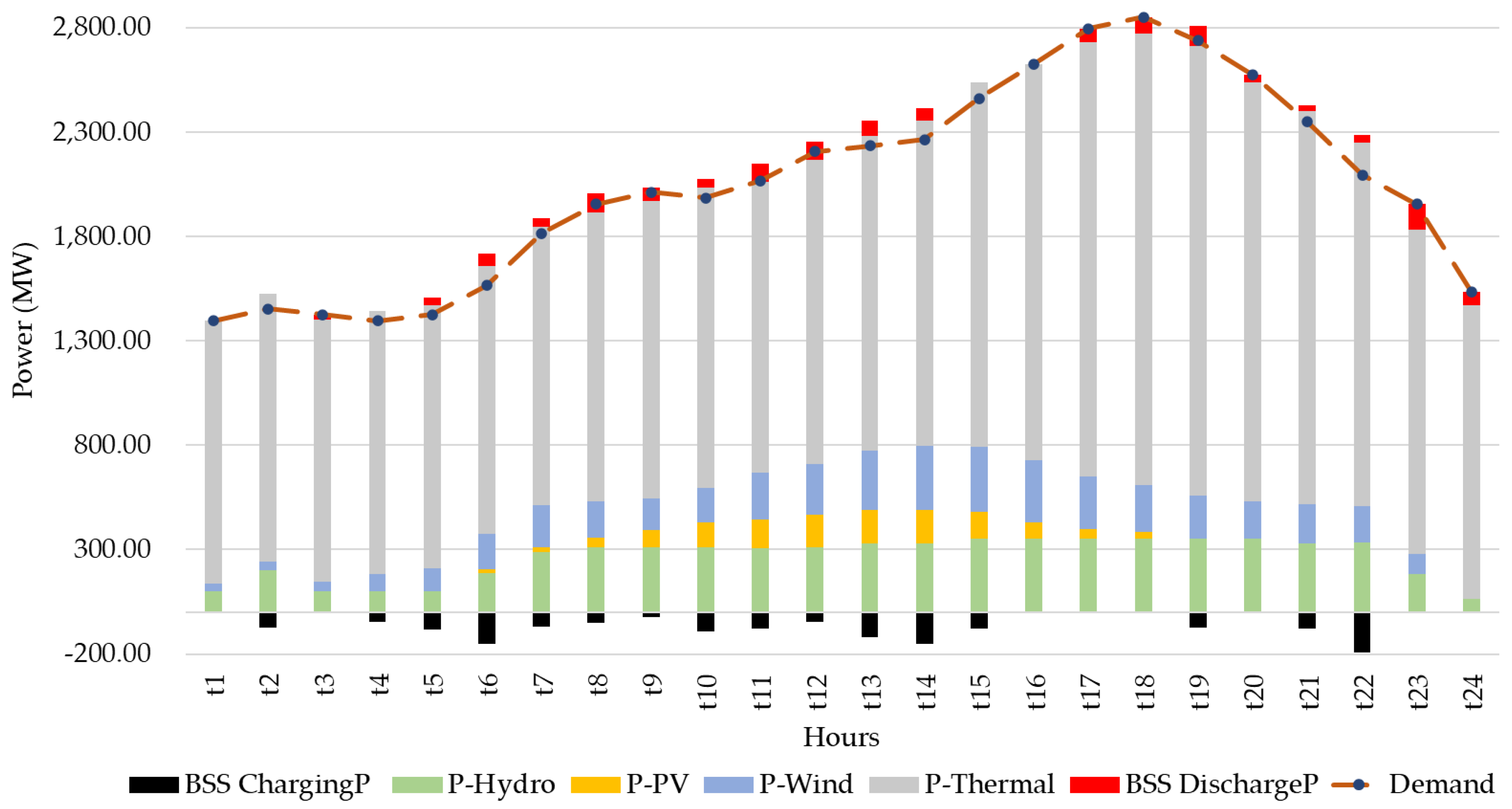
Figure 8.
Dispatch costs by type, of generation and storage.

Figure 9.
BESS in bar 8.
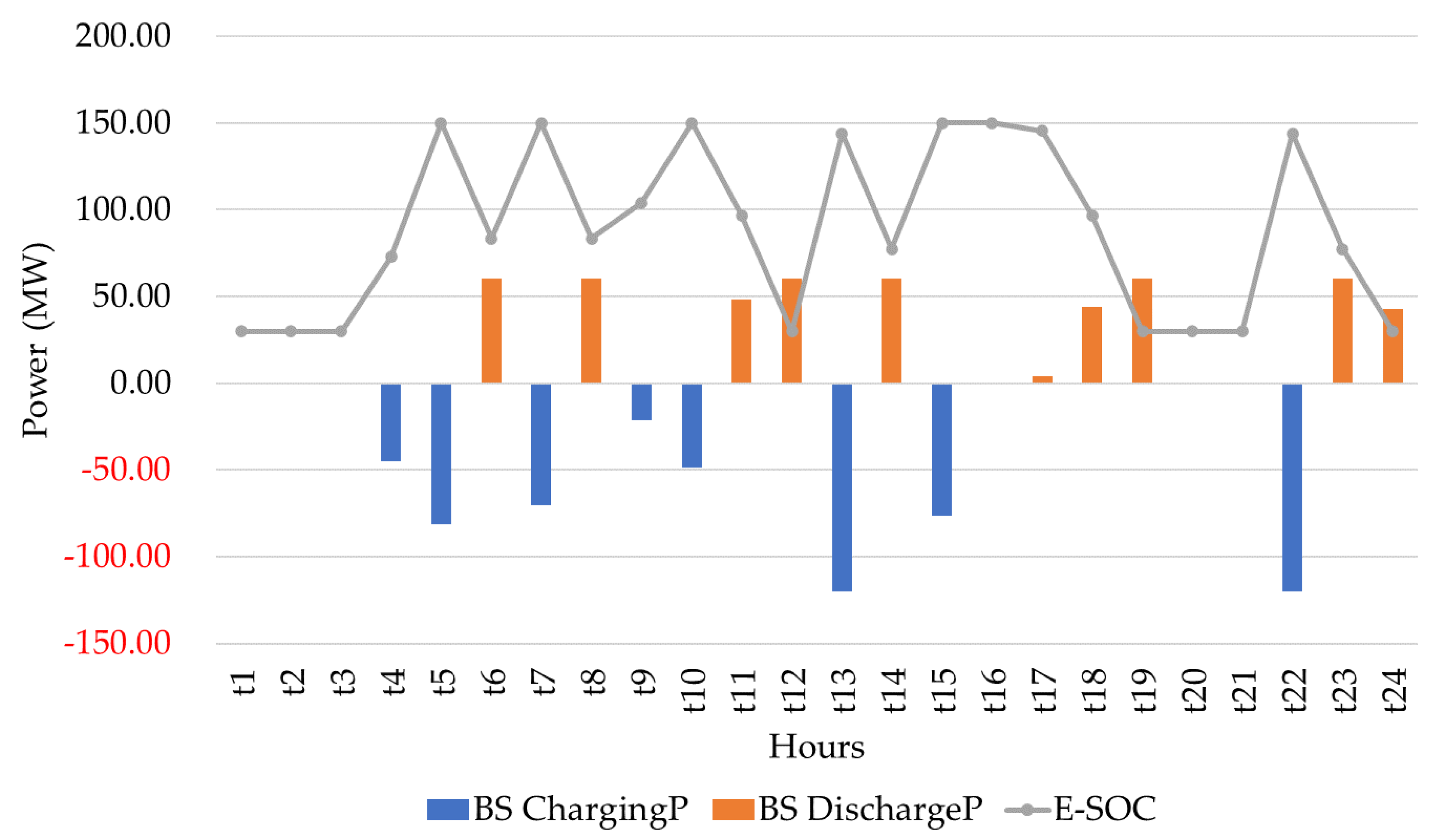
Figure 10.
BESS in bar 17.
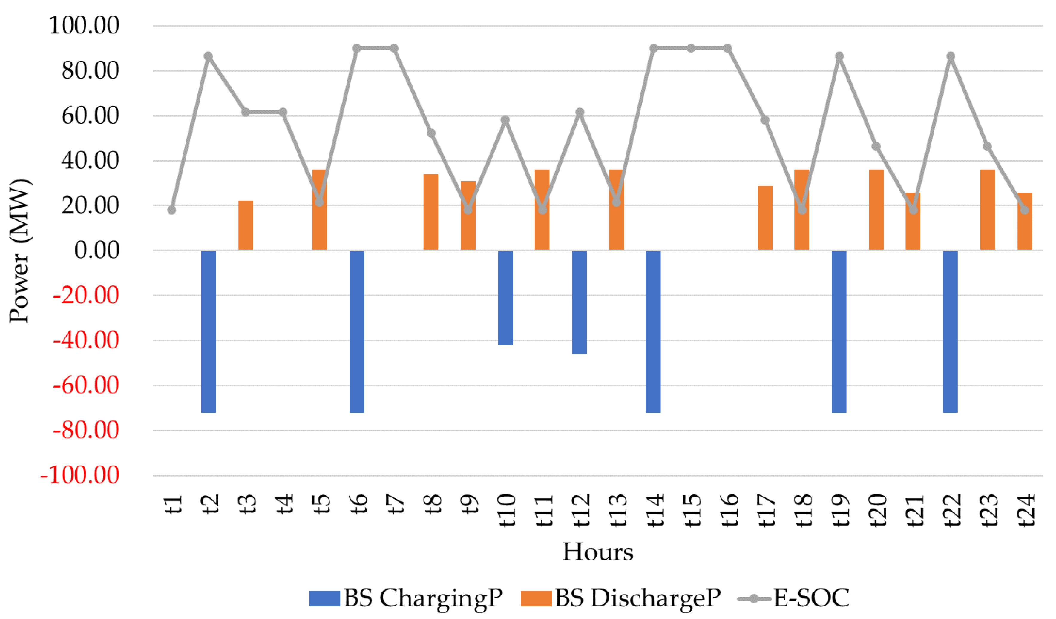
Figure 11.
BESS in bar 19.
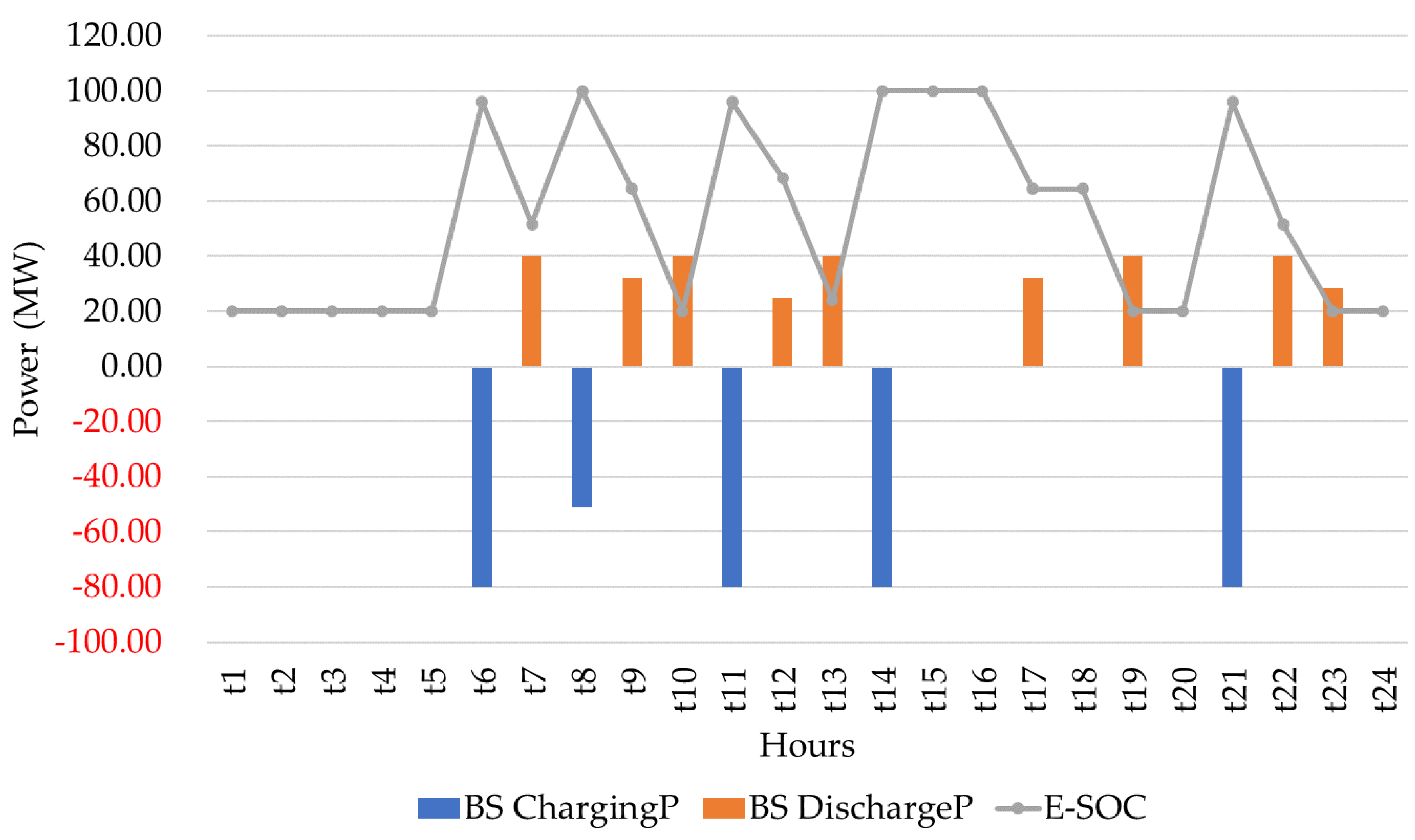
Figure 12.
The single-line diagram in maximum demand with storage systems.

Table 1.
Pseudocode.
| Optimal placement of storage systems using DC power flows. | |
| Step 1: | Absorption of technical data of the power system |
| Step 2 | Establishment of the components associated with the generation and transportation networks, as well as the factors related to the potential storage systems to be incorporated
|
| Step 3 | Determination of variables Continuous: |
| Step 4 | Optimization model formulation FO Minimize total operating costs, including the fees of energy that is not supplied to demand. Restrictions
|
| Step 5 | Implementation and solution of case studies |
| Step 6 | Studies of the responses were obtained. |
| Step 7 | End |
Table 2.
Technical parameters of conventional generation sources.
| Type | Bus | (MW) | (MW) | (MWh) | (MWh) | ($/MWh) | |
|---|---|---|---|---|---|---|---|
| u1 | T | 18 | 300 | 100 | 120 | 66.63 | 55.341 |
| u2 | T | 21 | 300 | 100 | 65 | 36.12 | 56.321 |
| u3 | T | 1 | 122 | 31 | 36 | 20.00 | 127.714 |
| u4 | T | 2 | 122 | 31 | 65 | 36.18 | 127.714 |
| u5 | T | 15 | 105 | 52 | 50 | 27.76 | 156.800 |
| u6 | T | 16 | 105 | 32 | 65 | 36.12 | 98.510 |
| u7 | T | 23 | 110 | 20 | 45 | 25.01 | 98.510 |
| u8 | T | 23 | 200 | 10 | 32 | 12.00 | 98.872 |
| u9 | T | 7 | 200 | 75 | 45 | 14.00 | 196.686 |
| u10 | T | 13 | 600 | 120 | 18 | 26.99 | 49.911 |
| u11 | T | 15 | 60 | 10 | 32 | 47.96 | 254.908 |
| u12 | T | 22 | 200 | 0 | 32 | 48.10 | 73.500 |
| u13 | H | 14 | 210 | 0 | 32 | 8.00 | 35.280 |
| u14 | H | 3 | 100 | 0 | 32 | 44.12 | 22.540 |
| u15 | H | 10 | 40 | 0 | 32 | 48.00 | 41.160 |
Table 3.
Parameters of non-conventional generation sources.
| Type | Bus | (MW) | (MW) | (USD/MWh) |
|---|---|---|---|---|
| E1 | 8 | 150 | 0 | 43 |
| E2 | 19 | 100 | 0 | |
| E3 | 21 | 80 | 0 | |
| FV1 | 17 | 90 | 0 | 38 |
| FV2 | 23 | 70 | 0 |
Table 4.
Renewable generation energy resource.
| E | FV | E | FV | ||
|---|---|---|---|---|---|
| t1 | 10.2% | 0.0% | t13 | 85.5% | 100.0% |
| t2 | 12.2% | 0.0% | t14 | 92.6% | 99.7% |
| t3 | 13.2% | 0.0% | t15 | 94.6% | 81.4% |
| t4 | 24.4% | 0.0% | t16 | 90.5% | 50.9% |
| t5 | 33.6% | 0.0% | t17 | 76.3% | 30.5% |
| t6 | 50.9% | 10.2% | t18 | 68.2% | 20.3% |
| t7 | 61.0% | 14.2% | t19 | 63.1% | 0.0% |
| t8 | 52.9% | 30.3% | t20 | 54.9% | 0.0% |
| t9 | 44.8% | 53.6% | t21 | 57.0% | 0.0% |
| t10 | 48.8% | 76.3% | t22 | 52.9% | 0.0% |
| t11 | 68.2% | 86.5% | t23 | 45.8% | 0.0% |
| t12 | 73.3% | 98.7% | t24 | 32.6% | 0.0% |
Table 5.
Characteristics of the bars.
| Bar | (MW) | Bar | (MW) |
|---|---|---|---|
| 1 | 108 | 13 | 265 |
| 2 | 97 | 14 | 194 |
| 3 | 180 | 15 | 317 |
| 4 | 74 | 16 | 100 |
| 5 | 71 | 17 | 0 |
| 6 | 136 | 18 | 333 |
| 7 | 125 | 19 | 181 |
| 8 | 171 | 20 | 128 |
| 9 | 175 | 21 | 0 |
| 10 | 195 | 22 | 0 |
| 11 | 0 | 23 | 0 |
| 12 | 0 | 24 | 0 |
Table 6.
Characteristics of the lines.
| Bar i | Bar j | X (pu) | Limit (MWA) |
|---|---|---|---|
| 1 | 2 | 0.0139 | 175 |
| 1 | 3 | 0.2112 | 175 |
| 1 | 5 | 0.0845 | 175 |
| 2 | 4 | 0.1267 | 175 |
| 2 | 6 | 0.192 | 175 |
| 3 | 9 | 0.119 | 175 |
| 3 | 24 | 0.0839 | 400 |
| 4 | 9 | 0.1037 | 175 |
| 5 | 10 | 0.0883 | 175 |
| 6 | 10 | 0.0605 | 175 |
| 7 | 8 | 0.0614 | 175 |
| 8 | 9 | 0.1651 | 175 |
| 8 | 10 | 0.1651 | 175 |
| 9 | 11 | 0.0839 | 400 |
| 9 | 12 | 0.0839 | 400 |
| 10 | 11 | 0.0839 | 400 |
| 10 | 12 | 0.0839 | 400 |
| 11 | 13 | 0.0476 | 500 |
| 11 | 14 | 0.0418 | 500 |
| 12 | 13 | 0.0476 | 500 |
| 12 | 23 | 0.0966 | 500 |
| 13 | 23 | 0.0865 | 500 |
| 14 | 16 | 0.0389 | 500 |
| 15 | 16 | 0.0173 | 500 |
| 15 | 21 | 0.0245 | 1000 |
| 15 | 24 | 0.0519 | 500 |
| 16 | 17 | 0.0259 | 500 |
| 16 | 19 | 0.0231 | 500 |
| 17 | 18 | 0.0144 | 500 |
| 17 | 22 | 0.1053 | 500 |
| 18 | 21 | 0.013 | 1000 |
| 19 | 20 | 0.0198 | 1000 |
| 20 | 23 | 0.0108 | 1000 |
| 21 | 22 | 0.0678 | 500 |
Table 7.
System charge behavior.
| h | (%) | h | (%) |
|---|---|---|---|
| t1 | 49.00 | t13 | 78.40 |
| t2 | 50.96 | t14 | 79.38 |
| t3 | 49.98 | t15 | 86.36 |
| t4 | 49.00 | t16 | 92.14 |
| t5 | 49.98 | t17 | 98.08 |
| t6 | 54.88 | t18 | 100.00 |
| t7 | 63.70 | t19 | 96.04 |
| t8 | 68.60 | t20 | 90.28 |
| t9 | 70.56 | t21 | 82.36 |
| t10 | 69.58 | t22 | 73.50 |
| t11 | 72.52 | t23 | 68.60 |
| t12 | 77.42 | t24 | 53.90 |
Table 8.
Data of potential BESS.
| Bar | ||
|---|---|---|
| BESS 1 | 19 | 100 |
| BESS 2 | 21 | 80 |
| BESS 3 | 8 | 150 |
| BESS 4 | 17 | 90 |
| BESS 5 | 23 | 70 |
Table 9.
Parameters for BESS.
| 20% | |
| 95% | |
| 90% |
Table 10.
Energy dispatch by technology.
| Technology | Bar | Energy (MWH) | Total (MWH) | Cost (USD) | Total (USD) |
|---|---|---|---|---|---|
| Hydro | bar 3 | 2400.00 | 6300.00 | 54,096.00 | 193,326.54 |
| bar 10 | 278.66 | 11,469.81 | |||
| bar 14 | 3621.34 | 127,760.7 | |||
| FV | bar 17 | 677.39 | 1204.24 | 25,740.63 | 45,761.12 |
| bar 23 | 526.86 | 20,020.49 | |||
| Wind | bar 8 | 1912.35 | 4208.36 | 82,231.05 | 180,959.48 |
| bar 19 | 1274.90 | 54,820.70 | |||
| bar 21 | 1021.11 | 43,907.73 | |||
| Thermal | bar 1 | 968.00 | 37,456.17 | 123,627.1 | 2,810,098.78 |
| bar 2 | 968.00 | 123,627.1 | |||
| bar 7 | 1961.10 | 385,720.9 | |||
| bar 13 | 14,361.5 | 716,795.4 | |||
| bar 15 | 1647.00 | 281,795.5 | |||
| bar 16 | 1204.63 | 118,668.3 | |||
| bar 18 | 6578.02 | 364,034.2 | |||
| bar 21 | 5285.95 | 297,709.8 | |||
| bar 22 | 1760.00 | 129,360.0 | |||
| bar 23 | 2722.00 | 268,760.3 | |||
| Total | 49,168.77 | 3,230,145.9 | |||
Table 11.
Power dispatched by technology.
| Technology | Bar | Power (MW) | Total (MW) |
|---|---|---|---|
| Hydro | bar 3 | 100.00 | 350.00 |
| bar 10 | 40.00 | ||
| bar 14 | 210.00 | ||
| FV | bar 17 | 18.32 | 32.56 |
| bar 23 | 14.25 | ||
| Wind | bar 8 | 102.30 | 225.06 |
| bar 19 | 68.20 | ||
| bar 21 | 54.56 | ||
| Thermal | bar 1 | 87.00 | 2242.38 |
| bar 2 | 87.00 | ||
| bar 7 | 138.38 | ||
| bar 13 | 600.00 | ||
| bar 15 | 115.00 | ||
| bar 16 | 105.00 | ||
| bar 18 | 300.00 | ||
| bar 21 | 300.00 | ||
| bar 22 | 200.00 | ||
| bar 23 | 310.00 | ||
| Total | 2850.00 | ||
Table 12.
Charge flow through the lines of the IEEE 24 busbar system.
| Bar | Flow (MW) | Bar | Flow (MW) | ||
|---|---|---|---|---|---|
| I | j | I | j | ||
| 1 | 2 | 19.15 | 13 | 12 | 188.12 |
| 1 | 5 | 8.92 | 14 | 11 | 139.00 |
| 2 | 6 | 12.81 | 15 | 24 | 146.82 |
| 3 | 1 | 49.07 | 16 | 14 | 123.00 |
| 3 | 9 | 17.75 | 16 | 15 | 10.88 |
| 4 | 2 | 3.66 | 16 | 19 | 73.06 |
| 7 | 8 | 13.38 | 17 | 16 | 201.94 |
| 9 | 4 | 77.66 | 18 | 17 | 88.76 |
| 9 | 8 | 38.33 | 20 | 19 | 39.74 |
| 10 | 5 | 62.08 | 21 | 15 | 337.94 |
| 10 | 6 | 123.19 | 21 | 18 | 121.76 |
| 10 | 8 | 16.99 | 22 | 17 | 94.86 |
| 11 | 9 | 138.77 | 22 | 21 | 105.14 |
| 11 | 10 | 180.78 | 23 | 12 | 122.84 |
| 12 | 9 | 134.48 | 23 | 13 | 33.66 |
| 12 | 10 | 176.48 | 23 | 20 | 167.74 |
| 13 | 11 | 180.55 | 24 | 3 | 146.82 |
Table 13.
Potential Bess data.
| Bar | Optimal BESS |
|---|---|
| 8 | √ |
| 17 | √ |
| 19 | √ |
Table 14.
Energy dispatch per generation and storage technology.
| Technology | Bar | Energy (MWH) | Total (MWH) | Cost (USD) | Total (USD) |
|---|---|---|---|---|---|
| BESS charge | bar 8 | −583.16 | −1402.15 | −127,097.1 | −305,593.91 |
| bar 17 | −448.00 | −97,639.96 | |||
| bar 19 | −370.99 | −80,856.82 | |||
| BESS discharge | bar 8 | 498.60 | 1198.84 | 13,144.38 | 31,604.51 |
| bar 17 | 383.04 | 10,097.92 | |||
| bar 19 | 317.20 | 8362.21 | |||
| Hydro | bar 3 | 2331.33 | 6300.00 | 52,548.18 | 194,611.58 |
| bar 10 | 348.42 | 14,341.05 | |||
| bar 14 | 3620.25 | 127,722.3 | |||
| FV | bar 17 | 677.39 | 1204.24 | 25,740.63 | 45,761.12 |
| bar 23 | 526.86 | 20,020.49 | |||
| Wind | bar 8 | 1912.35 | 4151.61 | 82,231.05 | 178,519.23 |
| bar 19 | 1255.98 | 54,007.14 | |||
| bar 21 | 983.28 | 42,281.04 | |||
| Thermal | bar 1 | 968.00 | 37,716.23 | 123,627.1 | 2,796,531.85 |
| bar 2 | 968.00 | 123,627.1 | |||
| bar 7 | 1837.10 | 361,331.8 | |||
| bar 13 | 14,337.0 | 715,574.0 | |||
| bar 15 | 1614.00 | 276,621.1 | |||
| bar 16 | 1206.00 | 118,803.1 | |||
| bar 18 | 7049.85 | 390,145.9 | |||
| bar 21 | 5388.30 | 303,474.5 | |||
| bar 22 | 1820.79 | 133,827.7 | |||
| bar 23 | 2527.19 | 249,499.4 | |||
| Total | 49,168.77 | 2,941,434.38 | |||
Table 15.
Power dispatched by technology with storage.
| Technology | Bar | Power (MW) | Total (MW) |
|---|---|---|---|
| BESS Charge | bar 8 | 43.76 | 79.76 |
| bar 17 | 36.00 | ||
| Hydro | bar 3 | 100.00 | 350.00 |
| bar 10 | 40.00 | ||
| bar 14 | 210.00 | ||
| FV | bar 17 | 18.32 | 32.56 |
| bar 23 | 14.25 | ||
| Wind | bar 8 | 102.30 | 225.06 |
| bar 19 | 68.20 | ||
| bar 21 | 54.56 | ||
| Thermal | bar 1 | 87.00 | 2162.62 |
| bar 2 | 87.00 | ||
| bar 7 | 75.00 | ||
| bar 13 | 600.00 | ||
| bar 15 | 104.00 | ||
| bar 16 | 105.00 | ||
| bar 18 | 300.00 | ||
| bar 21 | 300.00 | ||
| bar 22 | 200.00 | ||
| bar 23 | 304.62 | ||
| Total | 2850.00 | ||
Table 16.
Charge flow through the lines of the IEEE 24 busbar system with storage.
| Bar | Flow (MW) | Bar | Flow (MW) | ||
|---|---|---|---|---|---|
| i | j | i | j | ||
| 1 | 2 | 19.89 | 13 | 12 | 190.65 |
| 1 | 5 | 9.73 | 14 | 11 | 148.35 |
| 2 | 6 | 13.32 | 15 | 24 | 151.66 |
| 3 | 1 | 50.62 | 16 | 14 | 132.35 |
| 3 | 9 | 21.04 | 16 | 15 | 13.52 |
| 4 | 2 | 3.43 | 16 | 19 | 83.86 |
| 7 | 8 | 50.00 | 17 | 16 | 224.73 |
| 9 | 4 | 77.43 | 18 | 17 | 77.36 |
| 9 | 8 | 48.37 | 20 | 19 | 28.94 |
| 10 | 5 | 61.27 | 21 | 15 | 351.14 |
| 10 | 6 | 122.68 | 21 | 18 | 110.36 |
| 10 | 8 | 26.57 | 22 | 17 | 93.06 |
| 11 | 9 | 142.84 | 22 | 21 | 106.94 |
| 11 | 10 | 185.73 | 23 | 12 | 126.06 |
| 12 | 9 | 136.91 | 23 | 13 | 35.86 |
| 12 | 10 | 179.80 | 23 | 20 | 156.94 |
| 13 | 11 | 180.21 | 24 | 3 | 151.66 |
Disclaimer/Publisher’s Note: The statements, opinions and data contained in all publications are solely those of the individual author(s) and contributor(s) and not of MDPI and/or the editor(s). MDPI and/or the editor(s) disclaim responsibility for any injury to people or property resulting from any ideas, methods, instructions or products referred to in the content. |
© 2023 by the authors. Licensee MDPI, Basel, Switzerland. This article is an open access article distributed under the terms and conditions of the Creative Commons Attribution (CC BY) license (https://creativecommons.org/licenses/by/4.0/).
Share and Cite
MDPI and ACS Style
Rengel, A.; Téllez, A.A.; Ortiz, L.; Ruiz, M. Optimal Insertion of Energy Storage Systems Considering the Economic Dispatch and the Minimization of Energy Not Supplied. Energies 2023, 16, 2593. https://doi.org/10.3390/en16062593
AMA Style
Rengel A, Téllez AA, Ortiz L, Ruiz M. Optimal Insertion of Energy Storage Systems Considering the Economic Dispatch and the Minimization of Energy Not Supplied. Energies. 2023; 16(6):2593. https://doi.org/10.3390/en16062593
Chicago/Turabian StyleRengel, Andrés, Alexander Aguila Téllez, Leony Ortiz, and Milton Ruiz. 2023. "Optimal Insertion of Energy Storage Systems Considering the Economic Dispatch and the Minimization of Energy Not Supplied" Energies 16, no. 6: 2593. https://doi.org/10.3390/en16062593
Note that from the first issue of 2016, this journal uses article numbers instead of page numbers. See further details here.