Article

Performance Improvement of Grid-Integrated Doubly Fed Induction Generator under Asymmetrical and Symmetrical Faults

1
Department of Electrical Engineering, Mehran University of Engineering and Technology, Jamshoro 76062, Sindh, Pakistan
2
Department of Electronics and Communication Engineering, College of Engineering, A’Sharqiyah University, Ibra 400, North Sharqiyah Region, Oman
3
Department of Mechanical Engineering, Mehran University of Engineering and Technology, Jamshoro 76062, Sindh, Pakistan
4
Hawaii Natural Energy Institute, University of Hawaii at Manoa, Honolulu, HI 96822, USA
5
Institute of Energy Science—Vietnam Academy of Science and Technology, 18 Hoang Quoc Viet, Cau Giay, Hanoi 10072, Vietnam
6
Department of Engineering, University of Palermo, 90128 Palermo, Italy
*
Authors to whom correspondence should be addressed.
Energies 2023, 16(8), 3350; https://doi.org/10.3390/en16083350
Submission received: 6 March 2023 / Revised: 27 March 2023 / Accepted: 6 April 2023 / Published: 10 April 2023
(This article belongs to the Special Issue New Perspectives on Smart Grid and Sustainable Energy Systems)

Abstract

:
The doubly fed induction generator (DFIG)-based wind energy conversion system (WECS) suffers from voltage and frequency fluctuations due to the stochastic nature of wind speed as well as nonlinear loads. Moreover, the high penetration of wind energy into the power grid is a challenge for its smooth operation. Hence, symmetrical faults are most intense, inflicting the stator winding to low voltage, disturbing the low-voltage ride-through (LVRT) functionality of a DFIG. The vector control strategy with proportional–integral (PI) controllers was used to control rotor-side converter (RSC) and grid-side converter (GSC) parameters. During a symmetrical fault, however, a series grid-side converter (SGSC) with a shunt injection transformer on the stator side was used to keep the rotor current at an acceptable level in accordance with grid code requirements (GCRs). For the validation of results, the proposed scheme of PI + SGSC is compared with PI and a combination of PI with Dynamic Impedance Fault Current Limiter (DIFCL). The MATLAB simulation results demonstrate that the proposed scheme provides superior performance by providing 77.6% and 20.61% improved performance in rotor current compared to that of PI and PI + DIFCL control schemes for improving the LVRT performance of DFIG.

1. Introduction

With the addition of renewables to the existing grid, it may be possible to meet rising global energy demands. Wind energy is currently regarded as a clean, reliable, and affordable source of global power generation [1]. It is a significant component of the modern and future energy systems that use renewable energy [2]. Following this, cumulative installations of wind energy have witnessed rapid growth in the past two decades. The proportion of wind power installed throughout the world increased by 53% in 2020. This increases total installed capacity to 743 GW, a 14% increase over the preceding year [3]. It is a distributed energy source which can be combined with other power sources such as solar, thermal, hydroelectric, and natural gas to increase system reliability, availability, and power quality [4]. High penetration of wind energy meets the demand for energy, but it also raises issues for the smooth operation and grid integration of wind turbine generators [5]. Wind energy fluctuates; therefore, a new factor of uncertainty affects the power system stability and poses serious threats to wind energy planners and utility operators [6].
DFIG is widely utilized to harvest intermittent wind energy among all existing WECS technologies. Fractional power conversion ranges between 25–30 percent on the rotor side, low cost and power loss, quick power factor adjustment, high performance to transmit active and reactive power, higher efficiency, high power output, and outstanding power quality are only a few of the attractive qualities [7,8]. Thus, the grid integration of DFIG-based WECSs is suggested to maintain grid reliability and power quality at variable speed [9]. In addition, variable speed wind power operation results in a 20–25 percent increase in power output, improving the capacity factor and lowering per-unit operating costs [10]. Electrical faults at the point of interconnection with the power grid, on the other hand, are extremely dangerous for DFIGs [11]. Without any protection scheme, these voltage dips and disturbances at the PCC cause electromagnetic transients and may hamper the performance of the stator winding of DFIGs. Moreover, the magnetic coupling of the stator winding creates significant voltage in the rotor windings as a result of stator disturbances, resulting in uncontrolled rotor overcurrent [12]. Particularly, in the case of three-phase or symmetrical faults, overcurrent is produced in the power converter at the RSC and overvoltage in the DC bus capacitor. Consequently, the semiconductor switches at the RSC may be damaged, leading the DFIG to shut down. The LVRT improvement approach addresses symmetrical faults by ensuring work continues when the voltage drops and reducing re-synchronization issues after faults are fixed [13,14]. Modern grid codes require wind turbines (WT) to stay connected to the grid during transients and severe faults following a technical requirement called LVRT. It provides millisecond-reactive support to maintain stability of power grid [15].
The analysis of an LVRT improvement involves rotor current, stator active and reactive power, and DC link voltage. Rotor currents determine power converter stress during failures, so they must be below 2.0 pu to protect RSC switches [16]. However, it is preferable to have control over its tripping to prevent power and torque fluctuations. Keeping in view of the problem and its major consequences cited above, the DFIG LVRT strategy under faults at the PCC and power grid have been reported from time to time in the literature. It comprises two approaches: auxiliary hardware solutions and uninterruptable control improvements.
Hardware solutions such as crowbar equivalent circuits [17], static compensators (STATCOMs) [18], and dynamic voltage restorers (DVRs) [19] are used to partially solve LVRT problems. These techniques bypass the RSC, thereby reducing the rotor fault current or increasing the terminal voltage of the DFIG. However, most of them comprise complex control circuitry, modelled for reactive power compensation, and require a high cost of installation in wind power systems.
In addition to the aforementioned, LVRT control enhancements comprise field-oriented control (FOC) and direct torque/power control [20]. FOC is the most popular vector control method due to its simplicity and implementation. It responds inadequately to machine parameter changes and grid faults [21]. Alternatively, the DTC method directly controls the rotor flux by controlling electromagnetic torque, and it is independent of stator flux. However, it has no control over rotor overcurrent. Therefore, it needs improvement during voltage sags. Furthermore, direct power control (DPC) is dependent on variable switching frequency and is susceptible to stator current and power fluctuations [22]. In addition, effective electronic power converter control methods improve FRT DFIG capabilities at the lowest possible hardware cost. The FRT capabilities in DFIG are enhanced with a fuzzy logic controller in [23]. However, it does not comply with the GCR because it suffers from transient overcurrent in the rotor and overvoltage at the DC link voltage. Intelligent controllers in back-to-back PWM-VSI in DFIG-based WECS are difficult to implement due to the mathematical and computational challenges.
In contrast, a new simplified hardware approach utilizing fault current limiters (FCL) is presented to limit the short circuit current in the rotor to an acceptable value in accordance with GCR. In addition, it maintains the DFIG’s connection to the power grid in the event of symmetrical faults. The superconducting fault current limiter (SFCL) coil, during a severe three-phase-to-ground (3LG) fault, limits the rotor overcurrent [24]. A resistive-type SFCL coupled in series with the rotor has been investigated for rotor overcurrent protection in grid-integrated DFIGs [25]. This resistive-type SFCL uses a lot of electricity on the rotor side. However, the heat induced in SFCL requires tens of kWh for cooling. In addition, a new superconducting magnetic energy storage–fault current limiter (SMES-FCL)-based protection strategy uses modified SC and rotor-side converter control (RSC). Nevertheless, three-phase grid faults also cause large transient overcurrent in the stator and rotor windings and overvoltage in the DC link voltage [26]. Subsequently, FCL approaches are applied at different locations; therefore, they increase cost and power quality problems. For DFIG LVRT improvement, a superconducting magnetic energy storage (SMES) device based on a series-connected current source converter (CSC) is proposed. Despite this, both the stator and rotor windings experience transient overcurrent. In addition, the DC link output voltage is low and there are multiple voltage imbalances. Therefore, it poses a threat to the rotor and stator of the DFIG [27]. As such, it safeguards the back-to-back converters of grid-integrated DFIGs from any potential symmetrical faults.
The above discussion shows that dynamic response of grid-integrated DFIG under balanced and unbalanced faults has not been previously published. Therefore, this paper investigates dynamic response of symmetrical and asymmetrical fault for grid-integrated DFIG-WECS. DFIG may inject grid reactive power during grid failures. As such, the paper highlights shunt transformer interfaced series grid side converter (SGSC) technique to improve grid-integrated DFIG transient performance and grid code compliance.
The main contributions of the paper are listed as below:
-
This paper minimizes the rotor current at RSC during symmetrical faults considering grid code requirements.
-
The proposed scheme controls large variations in electromagnetic torque, rotor current, and stator active and reactive power during symmetrical faults.
-
It saves the rotor and stator from thermal breakdown; therefore, nuisance-tripping of protective devices may be avoided.
-
Comparing the proposed scheme with conventional PI controller and fault current limiter methods proves its superiority for LVRT improvement of grid-integrated DFIGs.
-
It provides a cost-effective way of enhancing the transient performance of DFIGs during faults.
The structure of the paper is described below. In Section 2, the problem formulation for DFIG is presented, which considers both symmetrical and asymmetrical faults. Section 3 reports the mathematical modeling of a wind turbine and DFIG. Section 4 elaborates the vector control structure using a PI controller for DFIGs. Section 5 discusses the auxiliary hardware using a shunt-transformer-interfaced SGSC system configuration incorporated with the stator of the DFIG. Section 6 addresses the effects of simulation for asymmetrical and symmetrical faults. Section 7 contains the conclusions of the work.

2. Problem Formulation

A fault in the power system is an abnormal state of the electrical system that causes a disruption or power breakdown. Unbalanced phases, under voltage, and overcurrent are all symptoms of an electrical fault in the system. These electrical faults are further classified into asymmetrical (SLG) and symmetrical (3-ϕ) faults.

2.1. Asymmetrical Faults

In asymmetrical faults, single line-to-ground (SLG) faults are more harmful and commonly occurring in wind power systems. In this type of fault, the single line becomes faulty while the other lines stay healthy. The analysis assumes the DFIG is operating normally before the asymmetrical fault occurs at a given time t o . Equation (1) shows the stator voltage for an asymmetrical fault:
v s = v s 1 + v s 2 v s 1 = V s 1 e j ω t , t o < 0 ( 1 p ) V s 1 e j ( ω t + θ 1 ) t o 0 v s 2 = 0 , t o < 0 q V s 2 e j ( ω t + θ 2 ) t o 0
where v s refers to stator voltage, p represents the depth of the positive sequence voltage sags, q indicates the magnitude of the negative sequence voltage, ω s refers to synchronous frequency, and θ 1 and θ 2 denotes phase angle jumps.
Equation (2) gives the stator flux ψ s during the single line-to-ground fault [28].
ψ s =   ψ s 1   +   ψ s 2   + ψ s n ψ s 1 = V s 1 e j ω t , t o < 0 ( 1 p ) j ω V s 1 e j ( ω s t + θ 1 ) t o 0 ψ s 2 = 0 , t o < 0 q j ω V s 2 e j ( ω s t + θ 2 ) t o 0 ψ s n = 0 , t o < 0 1 ( 1 p ) V s 1 e j θ 1 j ω + q j ω V s 2 e j θ 2 e t τ s t o 0
where ψ s 1 and ψ s 2 are the stator positive and negative flux components and ψ s n is the stator neutral component.
The stator and rotor fluxes are presented in Equation (3) and are expressed as follows [29]:
ψ s = L s i s + M i r ψ r = L r i r + M i s
The dynamic response of the stator flux can be estimated from Equations (1), (2), and (3) with an error of 10–20% [28].
ψ s = ( 1 p ) j ω V s 1 e j ( ω t + θ 1 ) + q j ω V s 2 e j ( ω t + θ 2 ) + ψ s n e t τ s  
where the stator decaying time constant is represented by τ s = σ L s R s .
Regarding Equation (2), the components of the stator flux for t t 0 can be subdivided as homogeneous (also known as natural) and non-homogeneous (also known as forced). The homogeneous component is the transient flux, and it has a decay rate that is exponential. This flux ensures that the magnetic state of the machine does not experience any discontinuities whenever the operating point is altered. The “forced flux” or non-homogeneous solution is the steady-state flux. This flux is proportional to grid voltage. Therefore, it corresponds to (1 − p) times the pre-fault value during the dip. In addition, the rotor voltage v r r   can be expressed in Equation (5) in terms of the stator flux and the rotor current, as shown here:
v r r = v r 0 + R r i r r + σ L r i r r
By introducing Equation (5) into Equation (4), the rotor emf can be obtained from Equation (6).
v r 0 = ( 1 p ) V s s k s e j ( s ω s t + θ 1 ) + k s ( 2 s ) q e j ( 2 s ) ( ω s t + θ 2 ) k s 1 τ s + j ω r ψ s n r e ( 1 τ s + j ω r ) t
Here, the coupling factor k s is expressed by the relationship k s = M L s .

2.2. Three-Phase Symmetrical Faults

A severe three-phase symmetrical low-impedance fault reduces stator voltage and flux to zero. The flux decays slower than voltage, according to the flux decay theorem. It can also be explained by the delay caused by inertial time lag τ s = L s R s affecting the rotor induced electromagnetic force (emf), v r o . The flux during the symmetrical fault is defined in Equation (7):
ψ s f = k s j ω r ψ s s e t / τ s
Therefore, the rotor induced voltage is expressed in Equation (8) as follows.
v r 0 = k s   ψ s r j ω r ψ s r
The derivative of ψ s f derived from Equation (7) is negative, indicating its decay. By substituting Equation (7) in Equation (8), Equation (9) is obtained as follows:
v o r s = k s t τ s + j ω r ψ s s e t / τ s
Equation (9) is converted to the rotor reference frame and to neglect t τ s :
v o r s = k s j ω r ψ s s e t / τ s
By substituting ψ s s = v s s j ω r e j ω s t in Equation (10), the pre-fault steady-state rotor voltage is obtained in Equation (11) [18]:
v o r s = k s j ω r v s s j ω r e j ω s t e t / τ s
Slip, s, is given by the expression s = ω s ω r ω s , where s ω s = ω s ω r and ω ω s = 1 s .
By substituting the stator voltage under symmetrical fault condition V s = v s s e j s ω s t in Equation (11), the expression can be obtained as:
v o r s = k s 1 s V s
where M , L s , and V s are positive constants. Therefore, v o r s is proportional to ( 1 s ) . It can further be written as:
v o r s = k ( 1 s )
where k is an integer constant and can be expressed as k = k s V s .
The analytics explain a significant drop in the pre-fault steady-state voltage to a specific fault voltage during a three-phase fault.

3. Modeling of Wind Turbine and DFIG

Figure 1 shows the generalized scheme of grid-integrated DFIGs. The three-blade horizontal axis wind turbine is used with the DFIG. Mathematical calculation is performed to measure the mechanical and aerodynamic power to determine the power output at different wind speeds. The DFIG comprises slip rings and carbon brushes connecting the distributed stator and rotor winding to the external circuit. The stator winding supplies its DFIG network with rated power. The DFIG rotor has a partial-scale bidirectional voltage source converter with an RSC, GSC, and DC link capacitor to maintain frequency and voltage stability at a variable speed.

3.1. Wind Turbine Model

Wind turbine models explain how wind speed affects power output. Therefore, the aerodynamic power P w of wind turbine presented in Equation (14) can be expressed as in [13,30].
P w = 1 2 ρ s w v w 3
where s w refers to swept area of the blades of wind turbines, s w = π R 2 .
The mechanical power P t expressed in Equation (15) is dependent on power coefficient Cp (λ, β) [31]. The mathematical expression of the power component is given by:
P t = 1 2 ρ C p ( λ , β ) s w v w 3
The Betz laws limits the captured power of a wind turbine to a fixed percentage of 59.3% [32]. In addition, the efficiency of the wind turbine is determined by an expression that is given by the tip speed ratio (TSR), which is provided in Equation (16) [33]:
λ = Ω t × R v w
The relationship of Cp and TSR presented in Equation (17) is given as follows [34]:
C p = c 1 ( c 2 λ 1 ) e c 3 λ
where c 1 , c 2 , and c 3 are positive constants. The wind turbine is capable of extracting maximum power if λ = λ o p t and C p = C p max .

3.2. System Configuration of DFIG

Globally, DFIG is recognized for facilitating the majority of large-scale wind power generation. It is applied for the wind turbines operating at variable wind speed and constant frequency. It has a distributed stator winding like the SCIG generator. In comparison, DFIG requires a two-phase bidirectional VSI along with a DC link capacitor in the rotor winding [35]. The most commonly used Park’s model for DFIGs is presented in Figure 2 [36].

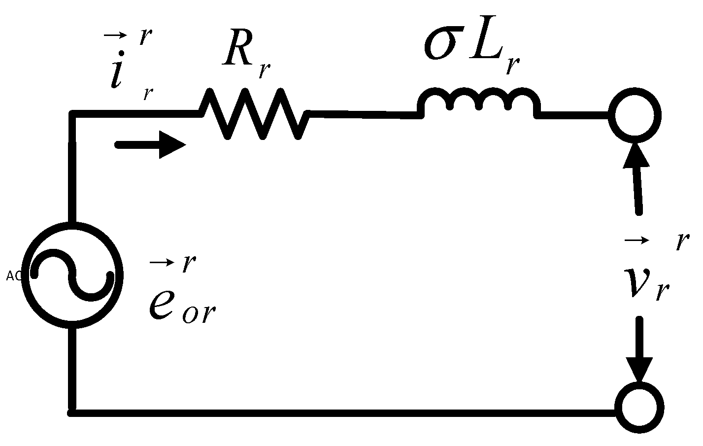
3.3. Mathematical Modeling of DFIG

The most commonly used Park’s model for DFIGs is presented in Figure 2 using a stationary reference frame [36]. The stator and rotor flux linkages are represented by ψ s and ψ r r . Therefore, stator and rotor voltages v s , v r r of a grid-integrated DFIG are expressed in Equation (18) using Park’s model as follows [37]:
v s = R s i s + ψ s   v r r = R r i r + ψ r r j ω r ψ r r  
The power grid directly interfaces with the stator winding in the DFIG, imposing stator voltage. Power converters control rotor voltage for machine control. Equation (19) shows the stator and rotor self-inductance [36]:
L s = L σ s + M L r = L σ r + M
R s , R r , L s , and L r refers to stator and rotor resistances and self-inductances, respectively. M denotes the magnetizing inductance. ω r is slip frequency. i s and i r represent stator and rotor current, respectively.
The d and q axis rotor voltages as expressed in Equation (20) in the synchronous reference frame linked to the rotor field [33], and are defined as:
v d r = R r i d r + ψ d r r ( ω s ω r ) ψ q r r v q r = R r i q r + ψ q r r + ( ω s ω r ) ψ d r r
where the rotor fluxes in the dq reference frame are expressed in Equation (21) as follows [33]:
ψ d r r = L r i d r + M i d s ψ q r r = L r i q r + M i q s
The rotor flux is directly affected by the stator flux. Using Equation (7), ψ r r is computed in Equation (22) and the following expression is obtained as:
ψ r r = k s ψ s r + σ L r i r r
Here, the coupling factor is expressed as k s = M L s and the leakage coefficient is represented by σ. It can be expressed as σ = 1 M 2 L s L r .
Substituting Equation (21) into Equation (18), the rotor voltage can be expressed in Equation (23) as follows [16]:
v r r = k s ψ s r j ω r ψ s r + R r i r r + σ L r ( i r r j ω r i r r )
The rotor voltage as given in Equation (23) is divided into two terms; the first term refers to the open-circuit voltage v r o and is due to stator flux. Under an open-circuit condition, the rotor current is zero and the rotor induced voltage given in Equation (24) can be expressed as:
v r 0 = k s   ψ s r j ω r ψ s r
The second term appears if rotor current exists. It is because of rotor resistance and transient rotor inductance, σ L r . Under normal operating conditions, steady-state flux induces rotor voltage. The open-circuited induced rotor voltage presented in Equation (25) can be written as:
v r 0 = k s   ψ s r
Therefore, using Equation (24) with Equation (23), the rotor voltage can be expressed as [18];
v r r = v r 0 + R r i r r + σ L r ( i r r j ω r i r r )  
where v r r , v r 0 , and i r r   represent rotor voltage, open-circuit rotor voltage, and rotor current on resistance and leakage inductance, respectively. RSC regulates the voltage across the rotor v r r , which is used for generator control. v r r can also be expressed in the rotor reference frame using stator flux and rotor current, as shown in Equation (27):
v r r = v r 0 + R r i r r + σ L r i r r
The schematic diagram of DFIG on the rotor side in the rotor reference frame is highlighted in Figure 3.

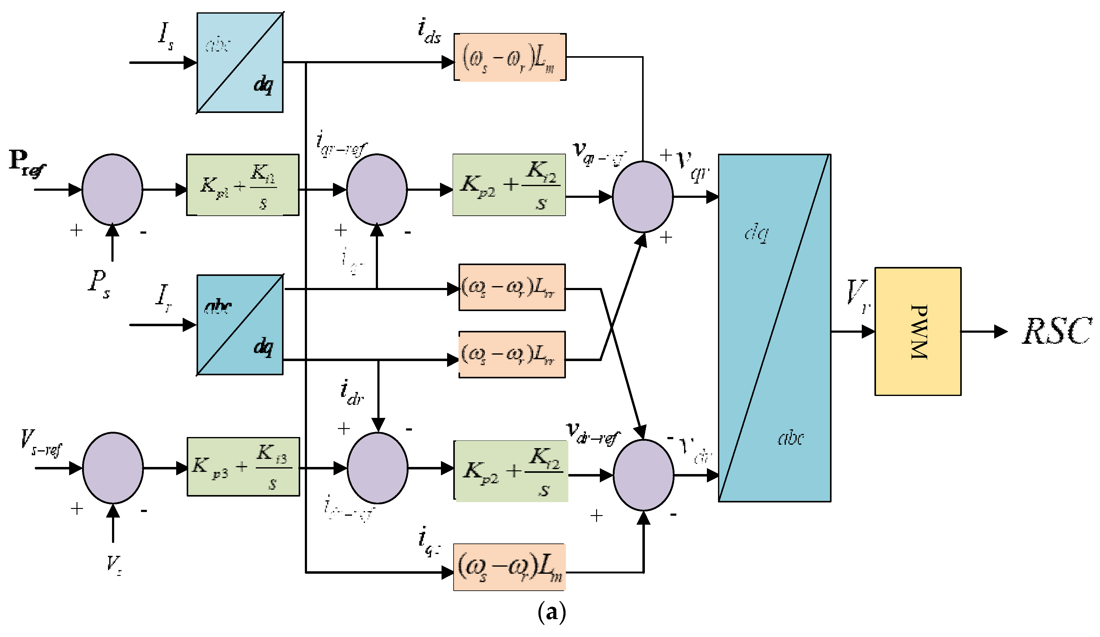
4. PI Control Structure in DFIG

For the RSC, independent control is achieved for active power and terminal voltage through v q r and v d r , respectively. Figure 4 shows PI-controlled RSC control. The rotor-side converter is d and q is the current control reference. V s r e f indicates the specified terminal voltage reference. P s r e f as given in Equation (28) refers to active power control.
P s r e f = P B ω t ω t B
The base rotating speed of a wind turbine is denoted by ω t B and PB designates its maximum active power. Error signals can be generated by comparing d-q current signals i d r and i q r to reference signals i d r _ r e f   and i q r _ r e f . The PI controller transmits these error signals from the voltage reference v q r r e f and v d r r e f . Cross-coupling compensates and sends voltage signals v d r and v q r to the PWM-VSC module. V r generates an IGBT gate control signal for RSC.
In Figure 4, the GSC independently controls Q g injected from the power grid and adjust the VDC at a nominal rating. v d g and v q g are used for independent control of VDC and Q g . V D C r e f is the dc link voltage reference, and Q g r e f refers to the reactive power control reference. x g is the transformer–transmission line reactance, expressed in Equation (29):
x g = x t + x l
The error signal is generated by comparing V D C with V D C r e f to form the reference signal i d g _ r e f by passing through the PI controller. These reference signals are compared to actual values i d g and i q g . Two PI controllers generate the voltage reference signals v d g r e f and v q g r e f from the error signal. Cross-coupling compensates the voltage reference signals to form voltage signals v d g and v q g , respectively. These signals are then transmitted to the PWM-VSC module, which is responsible for generating the IGBT gate control signals that are used to drive the GSC.
The turbine blade pitch must be controlled to keep the wind turbine rotating at the optimal speed. Figure 4 shows the schematic diagram. The pitch angle and wind turbine rotation speed change are denoted by β and ω t respectively.
It is necessary to maintain the rotating speed of the wind turbine at the optimal speed; therefore, the pitch of the turbine blades needs to be essentially controlled. The schematic diagram is shown in Figure 3, where ω t refers to the change in the rotating speed of the wind turbine and β denotes the pitch angle.

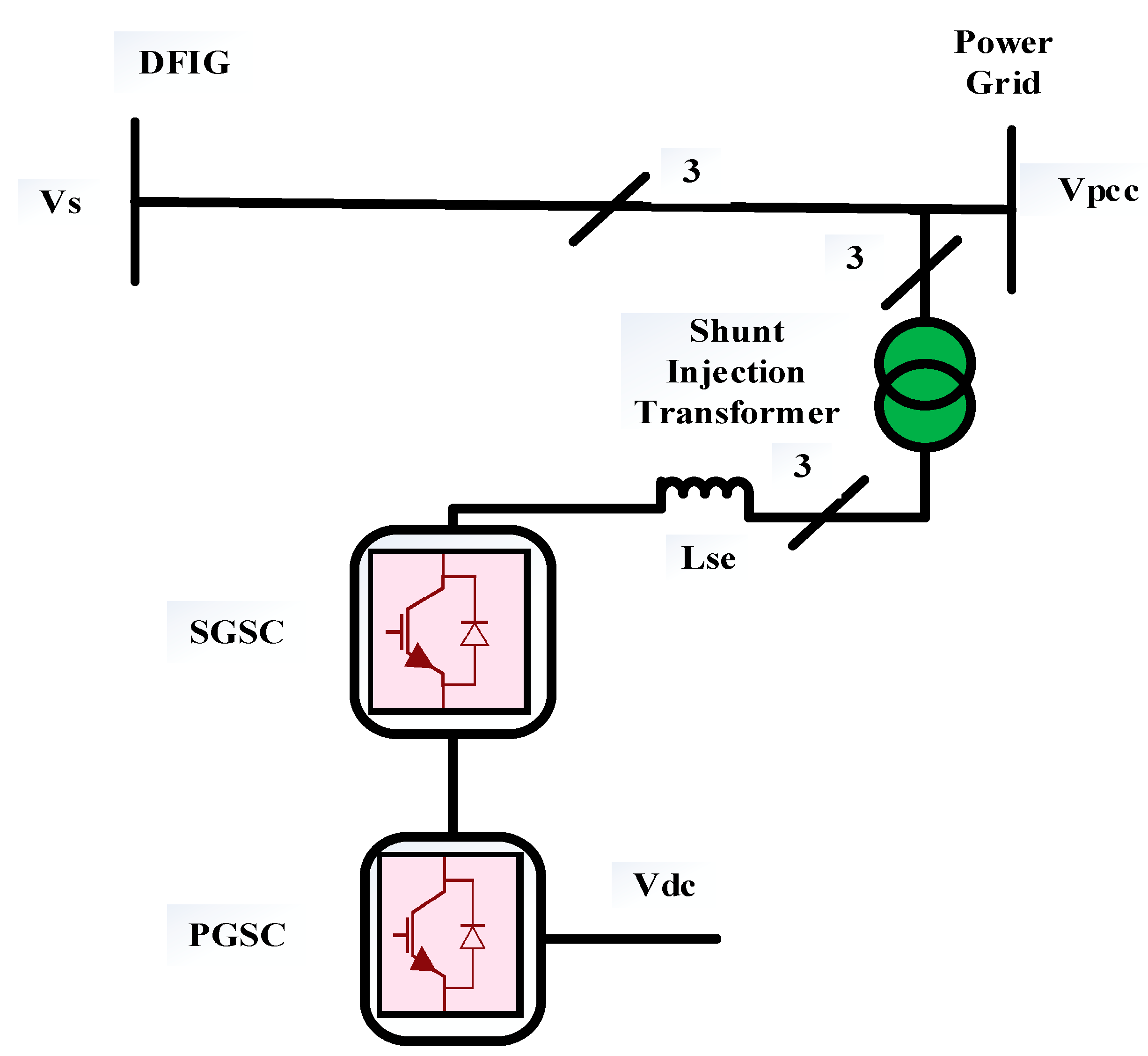
5. Shunt-Transformer-Interfaced SGSC System Configuration

Flannery and Venkataramanan suggested adding a grid-side converter in series with the generator’s stator windings to improve the LVRT performance of the DFIG during symmetrical faults [38]. The shunt injection transformer interfaced with a SGSC in Figure 5 is employed to compensate for PCC voltage dips caused by symmetrical faults. It improves LVRT by ensuring DFIG stator terminal sinusoidal voltage. The SGSC offers active series filtering, reactive power compensation, and electronic isolation [35].
The proposed scheme is connected to the DC link of a back-to-back converter. It serves the purpose of reducing rotor overcurrent and stator active and reactive power oscillations. Hence, sufficient power output is obtained after symmetrical fault clearance. Consequently, the wind power system operates long-term during steady-state grid voltage unbalance.
The simulation parameters of the 9 MW grid-integrated DFIG system and the proposed controller are provided in Table 1.
The comparative analysis of the parameters used for LVRT improvement are highlighted in Table 2. In this table, two techniques are compared with the proposed technique to highlight the LVRT improvement during symmetrical faults.

6. Results and Discussion

The simulations were carried out utilizing MATLAB; the environment parameters are listed in Table 1. Six 1.5 MW wind turbine generators (WTG) utilizing DFIG technology are connected to the medium voltage bus via the step-up transformer interfaced with PCC. The B 33 kV distribution feeder is connected to the power grid via a transmission line spanning 30 km. The parameters of the shunt injection transformer with series grid-side converter used for fault current limitation are listed in Table 2. The grid voltage, terminal voltage at PCC, and DFIG stator and rotor parameters are evaluated in pu, while P (MW), Q (MVar), and VDC (V) are evaluated in their respective SI units. The operation triggering time of the proposed grid-integrated DFIG model is between 0.2 ms and 0.3 ms, or between 0.2 ms and 100 ms. This time has been accounted for in accordance with grid code requirements.

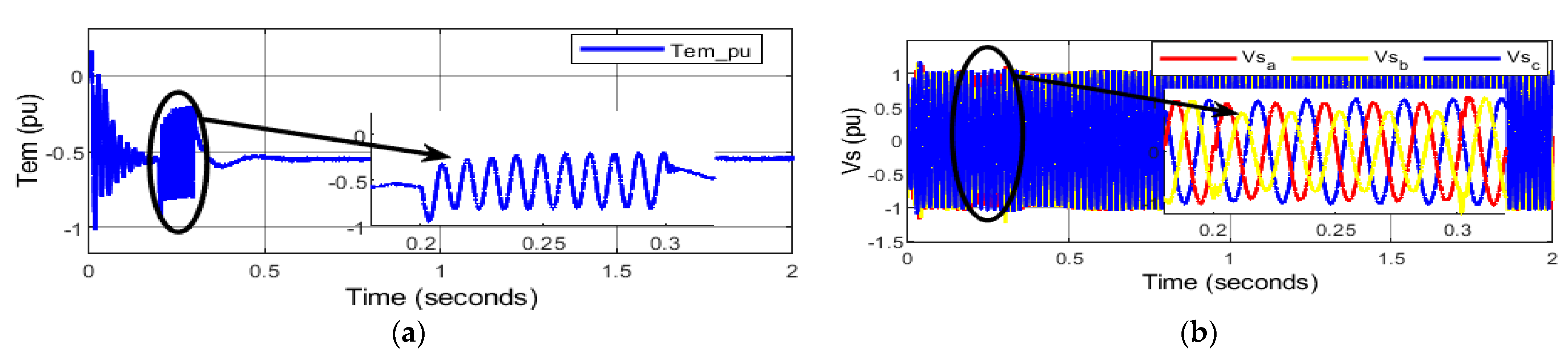
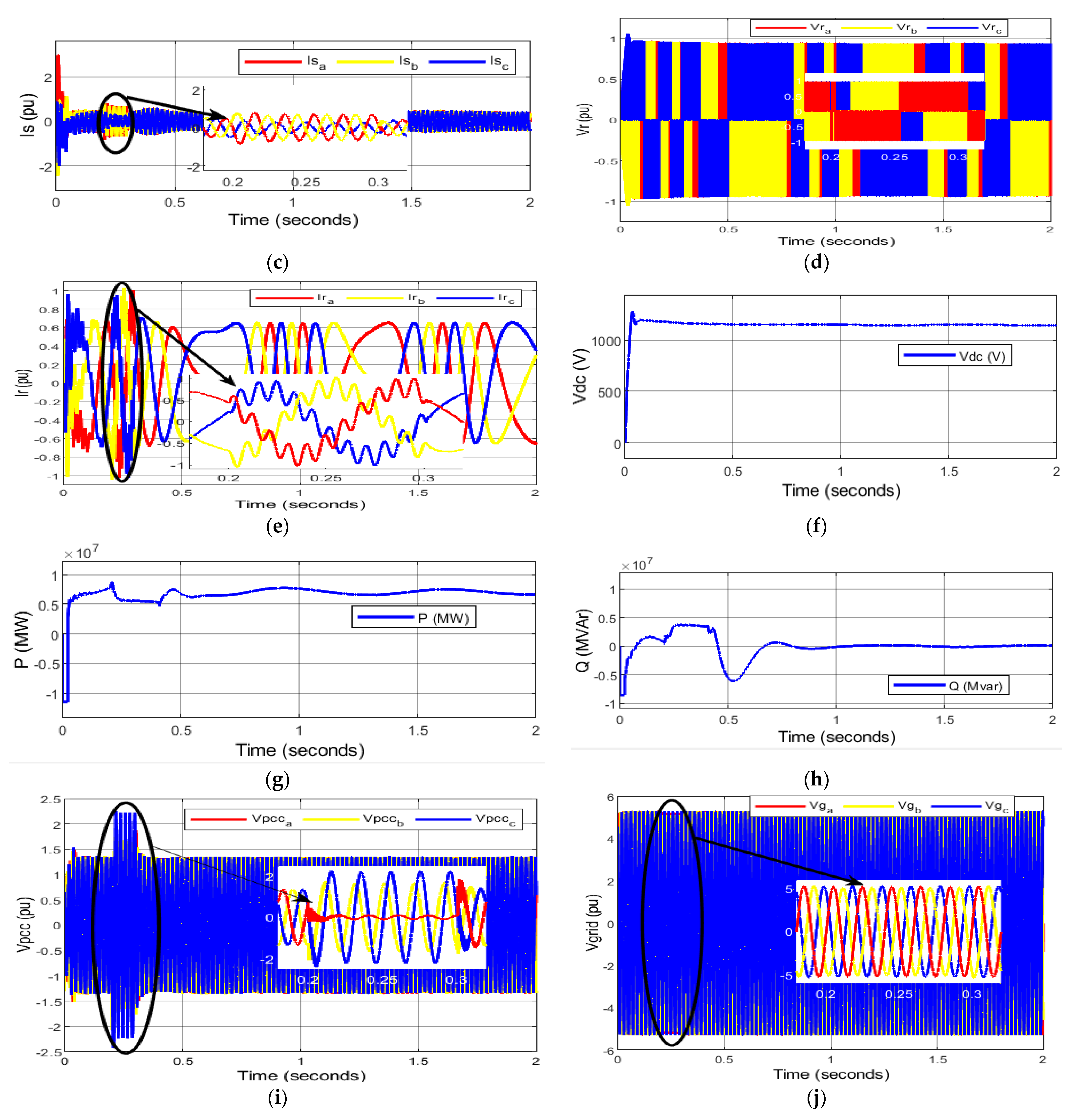
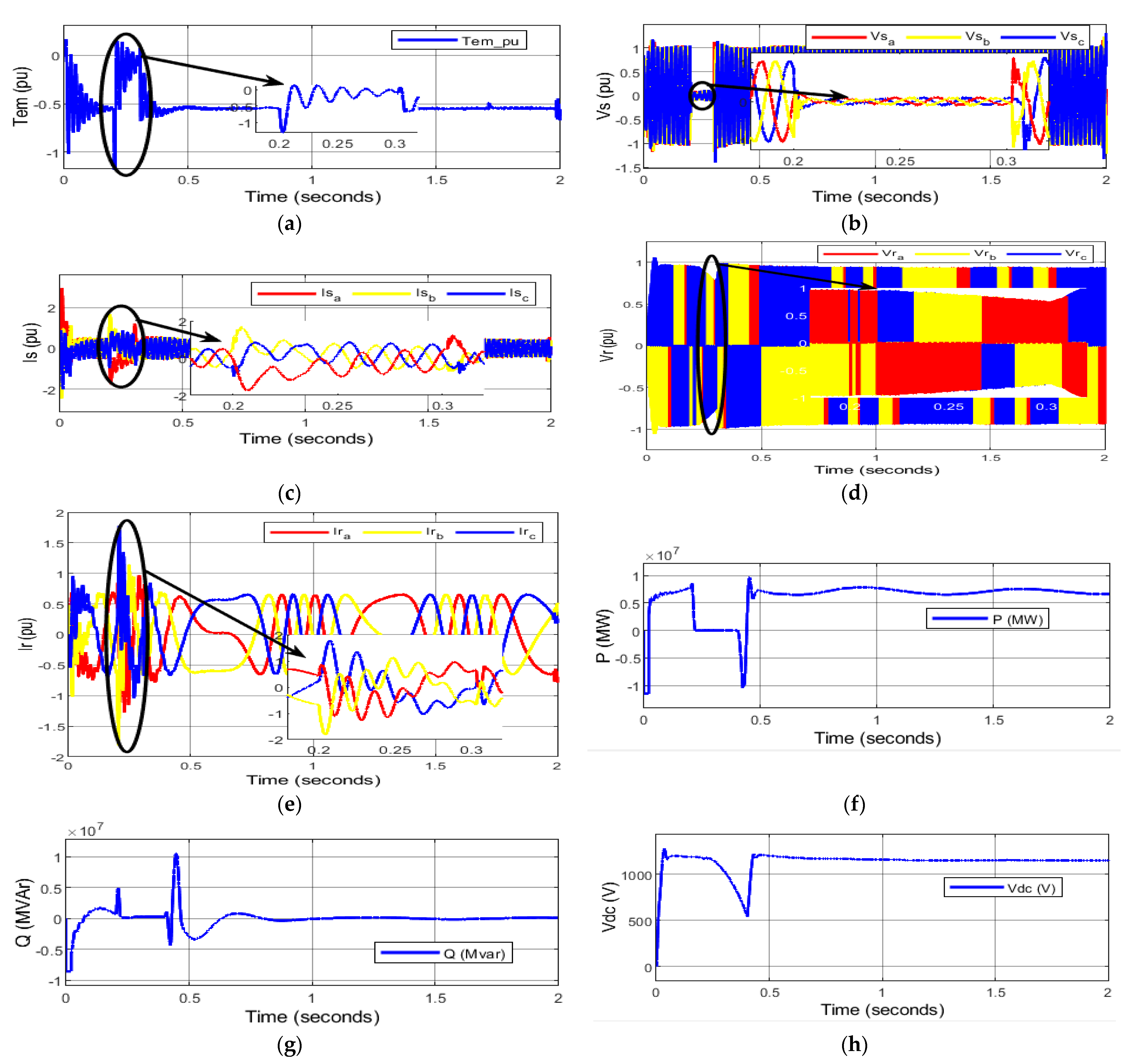
6.1. Asymmetrical Faults

In a DFIG-based WECS, asymmetrical faults are common but less severe [39]. They include SLG, LLG, and two-phase faults (LL). This paper discusses the behavior of a DFIG-based WECS during SLG fault using a PI controller without hardware protection.
Due to the low inertia of wind turbines, pre-fault oscillations in the behavior of electromagnetic torque of DFIG develop. The PI controller at the RSC, on the other hand, rapidly dampens these oscillations. The resultant electromagnetic torque undergoes brief oscillations of rising amplitude and frequency to a peak value of −0.8 pu at 0.2 s, the moment of the SLG fault at PCC, as presented in Figure 6a. If these oscillations continue, the DFIG’s reliability and gear lifetime may suffer. After the fault clears at 0.3 s, nevertheless, minor oscillations appear. The stator voltage is intended to run at 1.0 pu with its nominal auxiliary load. However, during the starting condition, the stator voltage fluctuations are observed which are later regulated by the PI controller. Figure 6b,c shows that the transient stator flux of DFIG causes the unbalanced voltage sag, which drops the voltage to 0.9 pu of nominal voltage during the asymmetrical fault for 100 ms. Thus, unbalanced stator overcurrent of 0.7 pu at fault causes high oscillations until the DFIG recovers from the SLG fault at 0.3 sec. Rotor overcurrent is caused by stator fault current passing through the magnetic coupling.
The rotor current during transient analysis is always kept below 2.0 pu (normally 200% of nominal value). At the PCC SLG fault, the DFIG-based WECS induces a large electromotive force (EMF) in the rotor voltage comprising homogeneous and non-homogeneous components. As such, damped homogeneous components can be zero after the fault. Non-homogeneous components, however, remain steady. Since the rotor voltage dip is small as shown in Figure 6d, the rotor current, which is 1 pu at the moment of fault, is controlled as shown in Figure 6e, and RSC is not at risk. Subsequently, the high amplitude of the rotor voltage and current gradually decreases as the rotor oscillations are damped down by the PI controller. However, the phase shift occurs at two durations, 0.4 s to 0.8 s and 1 s to 1.5 s; during these conditions, the phasors of rotor voltage and rotor current are highly unbalanced, causing serious power quality problems.
Apart from this, the VDC across the CDC during pre-fault conditions experiences a slight overshoot in the voltage, which later stabilizes instantly. The voltage dip is small during the SLG fault; therefore, no significant change in voltage appears across the DC link voltage from its nominal value during fault occurrence and post-fault periods, as shown in Figure 6f. It is higher than the nominal DC link voltage of 1150 V, which is unsafe for the DC link capacitor. Interestingly, the active power output rated at 9 MW as seen in Figure 6g is the minimum during the pre-fault period. However, it remains reduced during the SLG period, but it increases with oscillations once the fault is over. The power output increases and reaches nominal value, which indicates the efficacy of variable-speed wind power generation. Conversely, Figure 6h shows that the reactive power support of 4 MVAr is required at the instant of fault. This momentary injection of reactive power not only keeps the rotor magnetized and connected to the grid, but it also maintains stator and rotor voltage stability. The point of common coupling is the interface between the DFIG and step-up transformer. During an SLG fault, as highlighted in Figure 6i, a voltage imbalance takes place as the red phase is significantly affected at the moment of fault initiation. These frequent changes in voltage remaining during the fault period further deteriorate the current at the PCC which affects the power system stability. In the post-fault condition, the power system becomes stable and achieves a steady-state condition. Figure 6j shows that the grid voltage is not significantly affected by a voltage dip during the occurrence of the fault. However, after fault recovery, the grid voltage achieves a steady-state value.

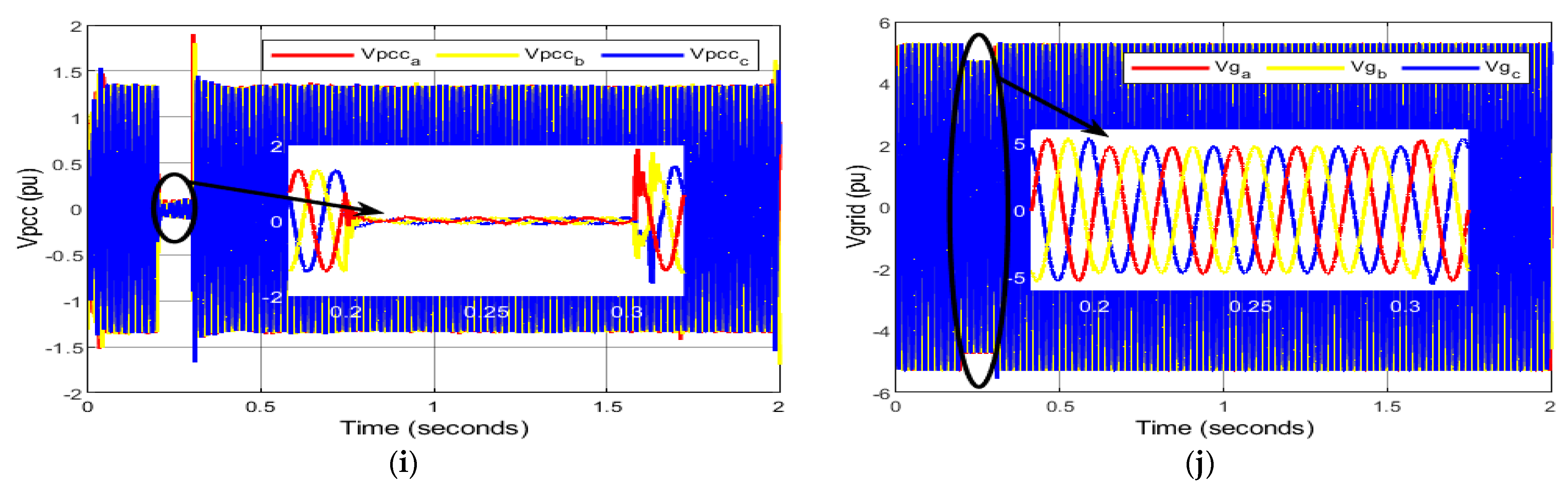
6.2. Symmetrical Faults

Asymmetrical faults are more harmful to the DFIG than symmetrical faults, since they induce higher current in the rotor. Those are much greater in effect than those appearing under normal operations. However, symmetrical or balanced faults rarely occur in the power grid. The dynamic responses of symmetrical grid faults prove most severe in a DFIG-based WECS. These faults develop significant impact on power quality, thereby affecting the grid code requirements. They comprise three-phase and three-phase-to-ground faults. In this paper, the dynamic response of three-phase faults has been discussed. The behavior of a DFIG-based WECS during asymmetrical faults using a PI controller without incorporating hardware protection is discussed below.
In this case, the induced rotor torque, as shown in Figure 7a, oscillates around the reference value during three-phase faults. However, it falls down to a peak value of −1.2 pu at 0.2 s during occurrence of a three-phase fault. The oscillations of unequal magnitude occur during the fault. However, these oscillations are damped down by the PI controller after the clearance of the fault. Later, it maintains a steady-state value after a few seconds. The stator winding of a DFIG is directly affected by changes in the power grid. Therefore, during three-phase faults at the PCC, there is significant change in the stator flux which causes the balanced voltage sag in stator winding. Hence, stator voltage significantly drops near to the minimum voltage but not zero as indicated in Figure 7b. The DFIG has a fine capability of low-voltage ride-through (LVRT) or fault ride-through (FRT) in accordance with grid code requirements; therefore, after clearance of the fault, DFIG remains connected to the power grid. However, a slight voltage swell occurs, but it is later regulated by the PI controller. The highly unbalanced stator overcurrent that is experienced is illustrated in Figure 7c and is caused by the balanced voltage sag that occurs under three-phase faults. The unbalanced stator current is slightly higher than 1.5 pu at the beginning of a three-phase fault, and it drops to 1 pu once the fault has been cleared. Whenever there is a drop in voltage or an increase in voltage, the transient stator flux will cause the rotor circuit to experience a sizeable electromagnetic field. Under severe fault conditions, the initial homogenous EMF might be so high that the RSC would be unable to neutralize the entire EMF. As a result, the DFIG would lose control of the situation. As a consequence of this, there is also a low-voltage sag in the rotor of the DFIG. In addition, it causes a surge current, also known as rotor overcurrent, which has values that are comparable to those of the stator overcurrent that are present during the fault period, as shown in Figure 7d,e, respectively. A stator/rotor winding overcurrent may be twice or more the nominal/rated current and appears as a hazardous risk to the electronic power converters of a DFIG. Therefore, current control is lost transitorily and, hence, damage is caused to the stator and rotor winding. Notably, its impact is critical on RSC, causing thermal breakdown.
Apart from it, in the pre-fault period, the machine accelerates its speed and acts as the doubly fed induction motor (DFIM) until it reaches the rated speed. Later on, the active power output is suddenly reduced to zero during the fault period and undergoes a sharp decrement in power at the clearance of the fault. On the other hand, the reactive power fluctuates above 0 MVAr—providing grid support to the DFIG-based WECS during the fault—but undergoes a steep increment in reactive power at the clearance of the fault as shown in shown in Figure 7f,g respectively. As soon as the three-phase fault is over, the active power output increases significantly. Similarly, reactive power maintains 0 MVAr, thereby allowing the DFIG to export the active power to the grid. The VDC rises above the nominal value as observed in Figure 7h at the instant of fault and it rises after the clearance of the fault. The ripples in the VDC are due to the transients in the Ir. Figure 7i shows that the terminal voltage at PCC also approaches 0 pu during the fault period. However, an overshoot in Vpcc is noticed after the post-fault period. The grid voltage also suffers from voltage sag as seen in Figure 7j due to the three-phase fault causing a serious power quality problem.

6.3. Shunt-Transformer-Interfaced Series Grid-Side Converter

The LVRT improvement requires the incorporation of a shunt injection transformer interfaced with the SGSC during three-phase faults. The proposed technique is compared with PI and PI + DIFCL control schemes. The electromagnetic torque oscillations become zero during the fault. However, these torque oscillations experience a peak value at the start and end of symmetrical faults as shown in Figure 8a. The DFIG performance is hampered by these rapid and massive torque variations, having a peak value of 1.5 pu at 0.21 s by the PI controller. The proposed SGSC scheme provides better and faster stabilization by reducing the peak value to 1.24 pu during the same period. On the other hand, the PI and PI + DIFCL control schemes give a peak rotor current value of 1.553 pu and 0.437 pu at 0.22 s, respectively, as shown in Figure 8b. Therefore, the proposed technique significantly reduces rotor current transients and maintains its value at 0.35 pu, which improves the transient performance of the rotor of the DFIG. The active power output using a PI controller acquires a peak value of 9.8 MW at 0.33 s as shown in Figure 8c, but the proposed technique provides 5.54 MW, showing less overshoot during the same period. Lastly, the reactive power has a peak value of 6.8 MVAr and 7.4 MVAr using the PI and PI + DIFCL control strategy at 0.326 s, as shown in Figure 8d. The proposed control scheme has a value of −9.87 MVAr. The lower value of reactive power is advantageous; therefore, the proposed technique gives better output with minimum oscillations.
The comparative analysis of symmetrical faults at the PCC of grid-integrated DFIG is shown in Figure 8. It has been found that the proposed technique provides distinct features of reducing the stator and rotor current and improving the DC link voltage. It not only maintains the LVRT performance of DFIG by connecting it to the grid but also increases the life span of rotor and stator winding and fragile converters affected through the fault.

7. Conclusions

In this paper, the dynamic behavior of both asymmetrical and symmetrical faults was analyzed in DFIG-based WECS. It was found that the proposed technique provided distinct features of reducing the stator and rotor current and improving the DC link voltage. It not only maintained the LVRT performance of DFIG by connecting it to the grid but also increasing the life span of rotor and stator winding and fragile converters affected through the fault. Based on these conditions, the proposed technique improves the LVRT performance of a DFIG during symmetrical fault at the PCC. Therefore, the proposed scheme works effectively for the LVRT improvement of DFIGs under symmetrical faults. For this purpose, simulation results verified the effectiveness of the proposed scheme by comparing it with PI controller and PI + DIFCL control schemes.
-
The electromagnetic torque oscillations are reduced by 17.3% using the proposed controller.
-
The proposed scheme presents 77.6% and 20.61% superior performance in rotor current limitation than that of PI and PI + DIFCL, respectively.
-
The proposed controller acquires 48.3% lower overshoot in active power output than that of PI controller.
-
The negative reactive power output in the proposed controller demonstrated that the reactive power was injected to the power grid, contributing towards the stability of a wind power system.
In the future, a static compensator (STATCOM) will be used at the PCC for the reactive power compensation and voltage stability of grid-connected DFIGs.

Author Contributions

Conceptualization, M.S., Z.A.M., M.H.B., N.H.M., L.K., Q.T.T. and G.Z.; formal analysis, M.S., Z.A.M., M.H.B., N.H.M. and L.K.; data curation, M.S., Z.A.M., M.H.B., N.H.M. and L.K.; writing—original draft preparation, M.S., Z.A.M., M.H.B., N.H.M., L.K., Q.T.T. and G.Z.; writing—review and editing, M.S., Z.A.M., M.H.B., N.H.M., L.K., Q.T.T. and G.Z.; visualization, M.S., Z.A.M., M.H.B., N.H.M., L.K., Q.T.T. and G.Z. All authors have read and agreed to the published version of the manuscript.

Funding

This research received no external funding.

Data Availability Statement

Data can be provided upon the request to the authors.

Acknowledgments

The directorate of Postgraduate Studies, Mehran University of Engineering and Technology, Jamshoro, Sindh, Pakistan, supported this research under the university support program.

Conflicts of Interest

The authors declare no conflict of interest.

Nomenclature

Model ParametersSymbolsModel ParametersSymbols
Stator and rotor voltage v s ,   v r Aerodynamic power P w
Depth of the positive sequence voltage sags p Swept area of the blades of wind turbine s w
Magnitude of the negative sequence voltage q Mechanical power P t
Synchronous frequency ω s Air density ρ
Phase angle jumps θ 1 ,   θ 2 Tip speed ratio (tsr) λ
Stator flux ψ s Coefficient of performance C p
Stator positive, negative, and neutral flux components ψ s 1 ,   ψ s 2 ,   ψ s n Pitch angle β
Coupling factor k s Wind speed v w
Stator and rotor resistances R s ,   R r Length of turbine blade R
Stator, rotor, and mutual inductances L s ,   L r ,   M Stator and rotor angular speed ω s ,   ω r
Stator decaying time constant τ s Electromagnetic torque T e m
Coupling factor k s No of pole pairs p p
Integer constantKSlipS

References

  1. Chaudhuri, A.; Datta, R.; Kumar, M.P.; Davim, J.P.; Pramanik, S. Energy Conversion Strategies for Wind Energy System: Electrical, Mechanical and Material Aspects. Materials 2022, 15, 1232. [Google Scholar] [CrossRef] [PubMed]
  2. Khare, V.; Nema, S.; Baredar, P. Solar–wind hybrid renewable energy system: A review. Renew. Sustain. Energy Rev. 2016, 58, 23–33. [Google Scholar] [CrossRef]
  3. Council, G.W.E. GWEC|Global Wind Report 2021. Glob. Wind. Energy Counc. Bruss. Belg. Available online: https://gwec.net/global-wind-report-2021/ (accessed on 5 March 2023).
  4. Basit, M.A.; Dilshad, S.; Badar, R.; Rehman, S.M.S.u. Limitations, challenges, and solution approaches in grid-connected renewable energy systems. Int. J. Energy Res. 2020, 44, 4132–4162. [Google Scholar] [CrossRef]
  5. Flynn, D.; Rather, Z.; Ardal, A.; D’Arco, S.; Hansen, A.; Cutululis, N.; Sorensen, P.; Estanquiero, A.; Gómez, E.; Menemenlis, N.; et al. Technical impacts of high penetration levels of wind power on power system stability. Wiley Interdiscip. Rev. Energy Environ. 2017, 6, e216. [Google Scholar] [CrossRef] [Green Version]
  6. Kroposki, B.; Johnson, B.; Zhang, Y.; Gevorgian, V.; Denholm, P.; Hodge, B.M.; Hannegan, B. Achieving a 100% renewable grid: Operating electric power systems with extremely high levels of variable renewable energy. IEEE Power Energy Mag. 2017, 15, 61–73. [Google Scholar] [CrossRef]
  7. Torkaman, H.; Keyhani, A. A review of design consideration for Doubly Fed Induction Generator based wind energy system. Electr. Power Syst. Res. 2018, 160, 128–141. [Google Scholar] [CrossRef]
  8. Tamalouzt, S.; Benyahia, N.; Rekioua, T.; Rekioua, D.; Abdessemed, R. Performances analysis of WT-DFIG with PV and fuel cell hybrid power sources system associated with hydrogen storage hybrid energy system. Int. J. Hydrog. Energy 2016, 41, 21006–21021. [Google Scholar] [CrossRef]
  9. Abozekry, M.; Osheba, D.; Azazi, H.; Osheba, S. Performance enhancement of a DFIG wind energy conversion system using phase advanced network. In IOP Conference Series: Materials Science and Engineering; IOP Publishing: Bristol, UK, 2018; Volume 459, p. 012007. [Google Scholar]
  10. Hamzah, N.H.; Usman, F. Geospatial analysis of wind velocity to determine wind loading on transmission tower. Wind. Struct. 2019, 28, 381–388. [Google Scholar]
  11. Naik, K.A.; Gupta, C.P.; Fernandez, E. Design and implementation of interval type-2 fuzzy logic-PI based adaptive controller for DFIG based wind energy system. Int. J. Electr. Power Energy Syst. 2020, 115, 105468. [Google Scholar] [CrossRef]
  12. Justo, J.J.; Mwasilu, F.A. Low voltage ride through enhancement for wind turbines equipped with DFIG under symmetrical grid faults. Tanzan. J. Eng. Technol. 2018, 37, 125–136. [Google Scholar] [CrossRef]
  13. Hossain, M.E. Low voltage ride-through capability improvement methods for DFIG based wind farm. J. Electr. Syst. Inf. Technol. 2018, 5, 550–561. [Google Scholar] [CrossRef]
  14. Qin, B.; Li, H.; Zhou, X.; Li, J.; Liu, W. Low-voltage ride-through techniques in DFIG-based wind turbines: A review. Appl. Sci. 2020, 10, 2154. [Google Scholar] [CrossRef] [Green Version]
  15. Huang, Q.; Zou, X.; Zhu, D.; Kang, Y. Scaled current tracking control for doubly fed induction generator to ride-through serious grid faults. IEEE Trans. Power Electron. 2015, 31, 2150–2165. [Google Scholar] [CrossRef]
  16. Amorim, A.E.; Carletti, D.; Fardin, J.F.; Encarnação, L.F.; Simonetti, D.S. A new hybrid multilevel converter for DFIG-based wind turbines fault ride-through and transient stability enhancement. Electr. Eng. 2020, 102, 1035–1050. [Google Scholar] [CrossRef]
  17. Yuan, Y.H.; Wu, F. Short-circuit current analysis for DFIG wind farm considering the action of a crowbar. Energies 2018, 11, 425. [Google Scholar] [CrossRef] [Green Version]
  18. Ananth, D.V.; Kumar, G.V.N. Fault ride-through enhancement using an enhanced field oriented control technique for converters of grid connected DFIG and STATCOM for different types of faults. ISA Trans. 2016, 62, 2–18. [Google Scholar] [CrossRef]
  19. Zhang, D.; Xu, H.; Qiao, L.; Chen, L. LVRT capability enhancement of DFIG based wind turbine with coordination control of dynamic voltage restorer and inductive fault current limiter. PLoS ONE 2019, 14, e0221410. [Google Scholar] [CrossRef] [Green Version]
  20. Kashkooli, M.A.; Madani, S.M.; Lipo, T.A. Improved Direct Torque Control for a DFIG under Symmetrical Voltage Dip with Transient Flux Damping. IEEE Trans. Ind. Electron. 2019, 67, 28–37. [Google Scholar] [CrossRef]
  21. Benbouhenni, H.; Bizon, N. Advanced Direct Vector Control Method for Optimizing the Operation of a Double-Powered Induction Generator-Based Dual-Rotor Wind Turbine System. Mathematics 2021, 9, 2403. [Google Scholar] [CrossRef]
  22. Gao, S.; Zhao, H.; Gui, Y.; Zhou, D.; Terzija, V.; Blaabjerg, F. A novel direct power control for DFIG with parallel compensator under unbalanced grid condition. IEEE Trans. Ind. Electron. 2020, 68, 9607–9618. [Google Scholar] [CrossRef]
  23. Duong, M.Q.; Leva, S.; Mussetta, M.; Le, K.H. A comparative study on controllers for improving transient stability of DFIG wind turbines during large disturbances. Energies 2018, 11, 480. [Google Scholar] [CrossRef] [Green Version]
  24. Salami, Y.; Firouzi, M. Dynamic performance of wind farms with bridge-type superconducting fault current limiter in distribution grid. In Proceedings of the 2011 2nd International Conference on Electric Power and Energy Conversion Systems (EPECS), Sharjah, United Arab Emirates, 15–17 November 2011; IEEE: New York City, NY, USA; pp. 1–6. [Google Scholar]
  25. Naderi, S.B.; Davari, P.; Zhou, D.; Negnevitsky, M.; Blaabjerg, F. A review on fault current limiting devices to enhance the fault ride-through capability of the doubly-fed induction generator based wind turbine. Appl. Sci. 2018, 8, 2059. [Google Scholar] [CrossRef] [Green Version]
  26. Xiao, X.-Y.; Yang, R.-H.; Chen, X.-Y.; Zheng, Z.-X.; Li, C.-S. Enhancing fault ride-through capability of DFIG with modified SMES-FCL and RSC control. IET Gener. Transm. Distrib. 2018, 12, 258–266. [Google Scholar] [CrossRef]
  27. Ren, J.; Xiao, X.; Zheng, Z.; Ma, Z. A SMES-Based Dynamic Current Limiter to Improve the LVRT Capability of DFIG-Based WECS. IEEE Trans. Appl. Supercond. 2021, 31, 1–5. [Google Scholar] [CrossRef]
  28. Geng, H.; Liu, C.; Yang, G. LVRT capability of DFIG-based WECS under asymmetrical grid fault condition. IEEE Trans. Ind. Electron. 2012, 60, 2495–2509. [Google Scholar] [CrossRef]
  29. Thomas, T.; Prince, A. LVRT capability evaluation of DFIG based wind energy conversion system under type-A and type-C grid voltage sags. In Proceedings of the 2020 IEEE International Conference on Power Electronics, Smart Grid and Renewable Energy (PESGRE2020), Cochin, India, 2–4 January 2020; IEEE: New York City, NY, USA, 2020; pp. 1–6. [Google Scholar]
  30. Baloch, M.H.; Ishak, D.; Chaudary, S.T.; Ali, B.; Memon, A.A.; Jumani, T.A. Wind power integration: An experimental investigation for powering local communities. Energies 2019, 12, 621. [Google Scholar] [CrossRef] [Green Version]
  31. Samokhvalov, D.V.; Jaber, A.I.; Filippov, D.M.; Kazak, A.N.; Hasan, M.S. Research of maximum power point tracking control for wind generator. In Proceedings of the 2020 IEEE Conference of Russian Young Researchers in Electrical and Electronic Engineering (EIConRus), St. Petersburg, Russia, 27–30 January 2020; IEEE: New York City, NY, USA, 2020; pp. 1301–1305. [Google Scholar]
  32. El Ghamrasni, M.; Mahmoudi, H.; Lagrioui, A.; Bossoufi, B. Comparison of Power Control Methods of DFIG for Wind Turbines. In Proceedings of the 2018 6th International Renewable and Sustainable Energy Conference (IRSEC), Rabat, Morocco, 5–8 December 2018; IEEE: New York City, NY, USA, 2018; pp. 1–8. [Google Scholar]
  33. Boubzizi, S.; Abid, H.; Chaabane, M. Comparative study of three types of controllers for DFIG in wind energy conversion system. Prot. Control. Mod. Power Syst. 2018, 3, 1–12. [Google Scholar] [CrossRef] [Green Version]
  34. Soomro, M.A.; Memon, Z.A.; Kumar, M.; Baloch, M.H. Wind energy integration: Dynamic modeling and control of DFIG based on super twisting fractional order terminal sliding mode controller. Energy Rep. 2021, 7, 6031–6043. [Google Scholar] [CrossRef]
  35. de Oliveira, Í.A.C.; Jacobina, C.B.; Rocha, N.; Rodrigues, P.L.S. Wind Energy Conversion System Based On DFIG With Three-Phase Series Active Filter And Single DC-Link. In Proceedings of the 2018 IEEE Energy Conversion Congress and Exposition (ECCE), Portland, OR, USA, 23–27 September 2018; IEEE: New York City, NY, USA; pp. 4544–4551. [Google Scholar]
  36. Tripathi, P.M.; Sahoo, S.S.; Chatterjee, K. Enhancement of low-voltage ride through of wind energy conversion system using superconducting saturated core fault current limiter. Int. Trans. Electr. Energy Syst. 2018, 29, e2798. [Google Scholar] [CrossRef]
  37. Patel, K.S.; Makwana, V.H. LVRT Fulfilment of the DFIG-based WECS During Symmetrical Grid Voltage Dips. IETE J. Res. 2022, 1–13. [Google Scholar] [CrossRef]
  38. Zhou, L.; Liu, J.; Zhou, S. Improved demagnetization control of a doubly-fed inductison generator under balanced grid fault. IEEE Trans. Power Electron. 2014, 30, 6695–6705. [Google Scholar] [CrossRef]
  39. Rashid, G.; Ali, M.H. Fault ride through capability improvement of DFIG based wind farm by fuzzy logic controlled parallel resonance fault current limiter. Electr. Power Syst. Res. 2017, 146, 1–8. [Google Scholar] [CrossRef]
Figure 1. Simplified block diagram of grid-integrated DFIG-based WECS with auxiliary SGSC.
Energies 16 03350 g001
Figure 2. DFIG-equivalent circuit diagram for transient analysis in a stationary reference frame.
Energies 16 03350 g002
Figure 3. DFIG rotor-side circuit diagram for transient analysis in a rotor reference frame.
Energies 16 03350 g003
Figure 4. Schematic control diagram of (a) RSC, (b) GSC and (c) pitch controller.
Energies 16 03350 g004aEnergies 16 03350 g004b
Figure 5. Schematic diagram of a shunt-transformer-interfaced SGSC.
Energies 16 03350 g005
Figure 6. Behavior of DFIG-based WECS during single line-to-ground fault. (a) Per unit electromagnetic torque; (b) per unit stator voltage; (c) per unit stator current; (d) per unit rotor voltage; (e) per unit rotor current; (f) DC link voltage; (g) active power (MW); (h) reactive power (MVAr); (i) per unit voltage at PCC; (j) per unit grid voltage.
Energies 16 03350 g006aEnergies 16 03350 g006b
Figure 7. Behavior of DFIG-based WECS during three-phase fault without protection. (a) Per unit electromagnetic torque; (b) per unit stator voltage; (c) per unit stator current; (d) per unit rotor voltage; (e) per unit rotor current; (f) DC link voltage; (g) active power (MW); (h) reactive power (MVAr); (i) per unit voltage at PCC; (j) per unit grid voltage.
Energies 16 03350 g007aEnergies 16 03350 g007b
Figure 8. Behavior of DFIG-based WECS during three-phase fault with shunt-transformer-interfaced auxiliary SGSC. (a) Per unit electromagnetic torque; (bd) per unit rotor currents; (e) stator active power (MW); (f) stator reactive power (MVAr).
Energies 16 03350 g008
Table 1. Simulation parameters of grid-integrated DFIG.
DescriptionSymbolValueDescriptionSymbolValue
Stator voltageVs,B575 VThree-Phase Transformer Parameters
Apparent stator powerSB10 MVATransformer voltage at PCCVN575/33 kV
WT Parameters Mode of connectionD11/Yg
No of pole pairsPp03Grid Voltage Parameters
Inertia constantJ4 HGrid transformer voltageVN33 kV/132 kV
FrequencyF50 HzGround powerPg47 MVA
DFIG Parameters Mode of connectionVg/D11
Stator resistanceRs0.23 puPI Controller Parameters
Stator inductanceLs0.31 puDC link voltage gainsKp,DC Ki,DC0.025 p.u, 25 s−1
Rotor resistanceRr0.06 puRSC gainsKpRSCKiRSC0.6 p.u, 8 s−1;
Rotor inductanceLr0.16 puGSC gainsKpGSC KiGSC0.83 p.u, 5 s−1
Magnetizing inductanceM2.91 puTurbine speed gainsKpWT, KiWT3 p.u, 0.6 s−1
Stator active powerPs9 MWShunt Injection Transformer with SGSC
DC link capacitorCDC6.6 mFShunt injection T/f voltageVsh575/1725 V
DC link voltageVDC1150Series inductanceLs0.001 H
Decaying time constantτs6.6 × 10−6 s
Table 2. Comparative analysis of responses of different control schemes during symmetrical fault.
ParametersPIDIFCLSGSC
Tem−1.5 pu0.034 pu−1.24 pu
Ir1.553 pu0.437 pu0.3469 pu
Ps10 MW0.98 MW5.17 MW
Qs6.8 MVAr7.4 MVAr−1 MVAr
Disclaimer/Publisher’s Note: The statements, opinions and data contained in all publications are solely those of the individual author(s) and contributor(s) and not of MDPI and/or the editor(s). MDPI and/or the editor(s) disclaim responsibility for any injury to people or property resulting from any ideas, methods, instructions or products referred to in the content.

