

Hybrid Surrogate Model-Based Multi-Objective Lightweight Optimization of Spherical Fuel Element Canister
Abstract
:1. Introduction
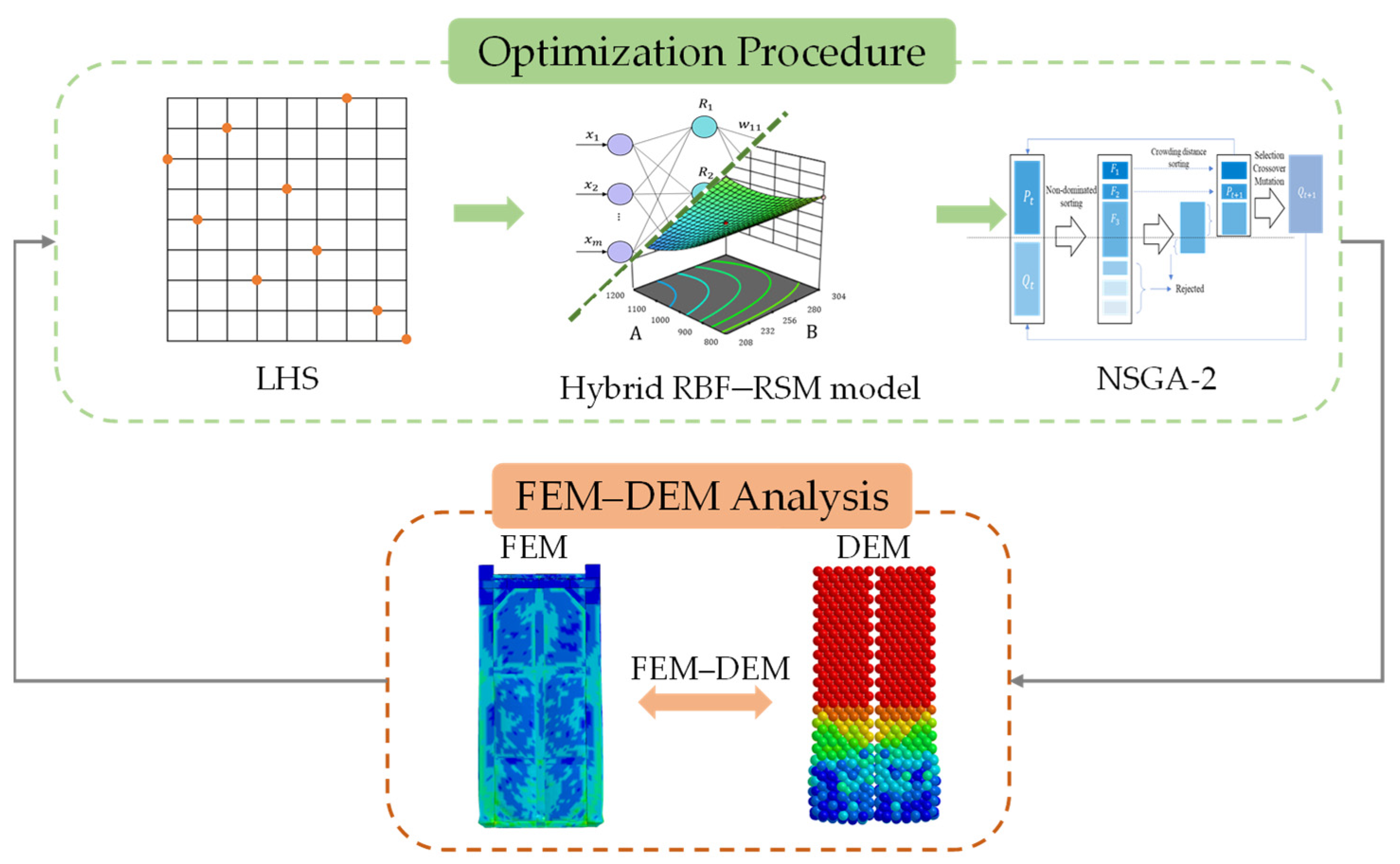
2. The Optimization Procedure
2.1. Description of the Problem
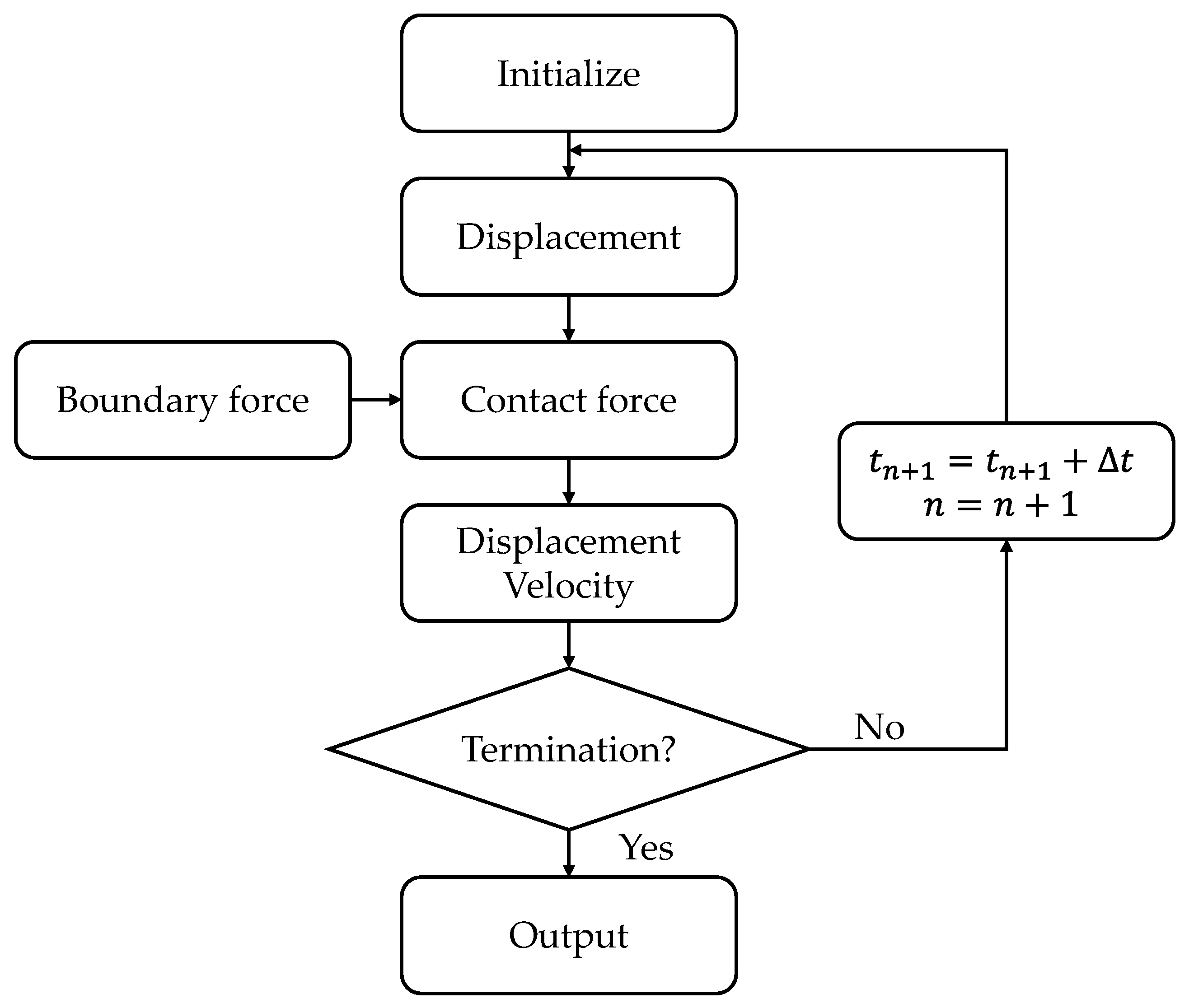
2.2. FEM–DEM Method
2.3. Surrogate Model
2.4. NSGA-II Algorithm
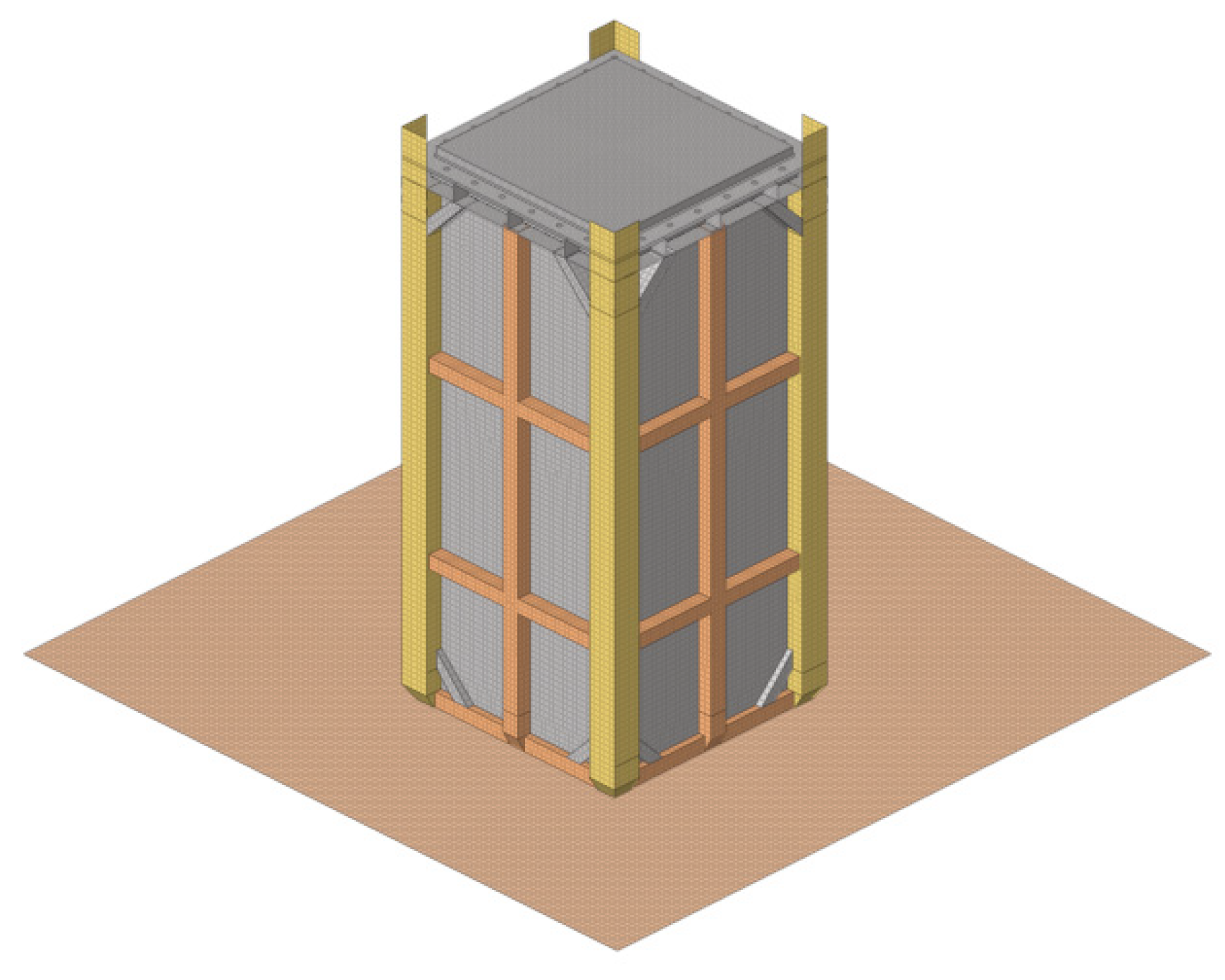
3. SFE Canister Model
3.1. Canister Model
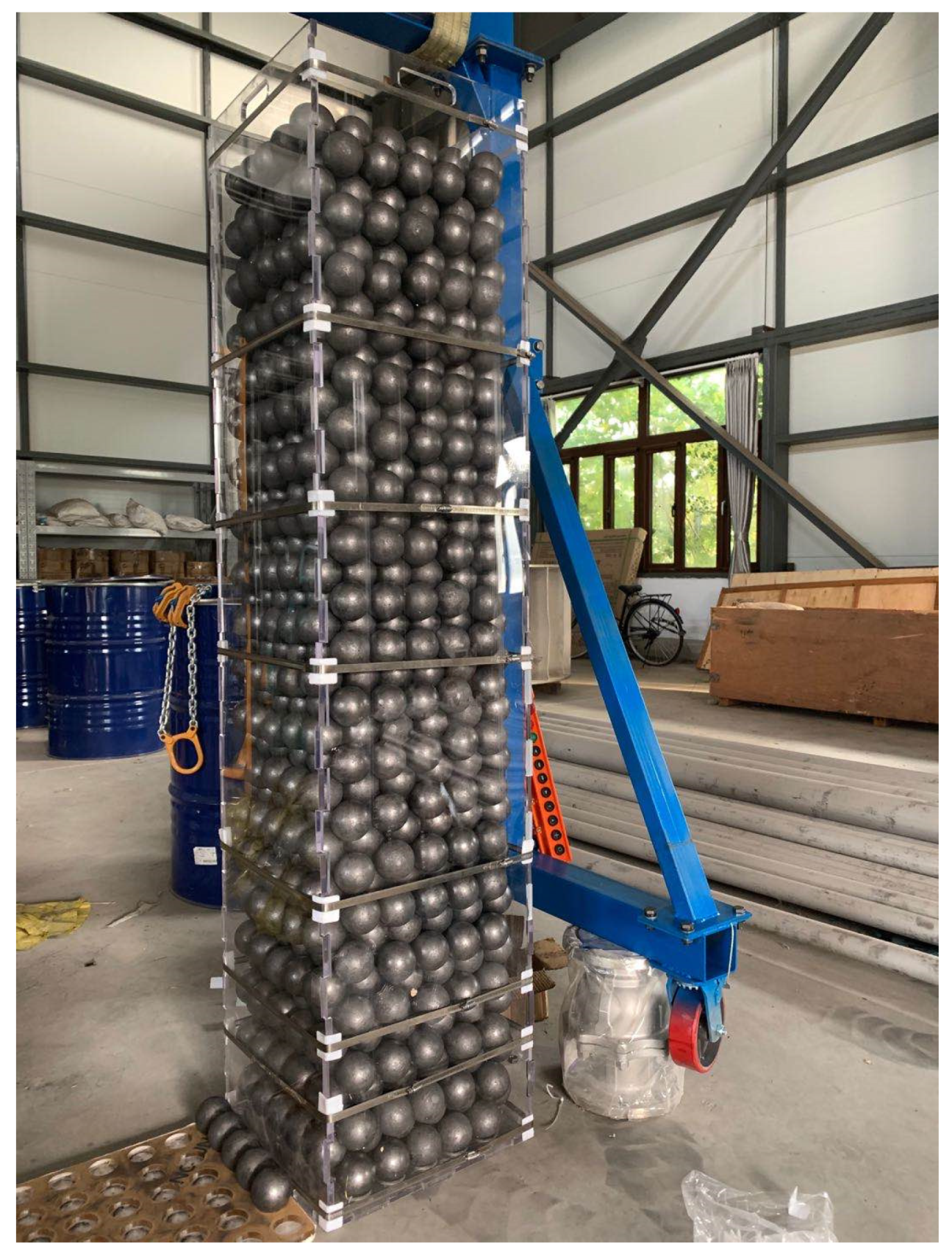
3.2. SFE Model
3.3. The Simulation of Drop Process
3.4. Initial Analysis
- The weight of the SFE canister is 569 kg, which is expected to be designed as light as possible.
- The effective plastic strain is selected as the safety indicator to describe the deformation of the containment boundary of SFE, with a value of 23.76%.
4. Multi-Objective Optimization Problem
4.1. Design Variables and Objective
4.2. Surrogate Model Based on LHS
5. Result and Discussion
6. Conclusions
- The deformation and displacement of the canister and SFEs under impact loading could be obtained through the drop analysis model integrating the FEM–DEM method.
- The hybrid RBF–RSM model has been validated with high accuracy based on , RMSE, and the simulation-prediction comparison. It is believed to approximate precisely the accurate but high-cost simulation model.
- The calculation result shows that up to 2.45% reduction of mass and 44.65% reduction of the plastic strain could be realized, while the optimal canister can protect SFEs well in the extreme event, indicating the multi-objective lightweight canister is designed successfully.
- In future investigations, it might be possible to consider shape optimization, topological optimization, and multidisciplinary design optimization for expansion.
Author Contributions
Funding
Data Availability Statement
Conflicts of Interest
References
- Kugeler, K.; Zhang, Z. Fuel Elements. In Modular High-Temperature Gas-Cooled Reactor Power Plant; Springer: Berlin/Heidelberg, Germany, 2019. [Google Scholar] [CrossRef]
- Li, L.; Yuan, H.; Wang, K. Coupling of RMC and CFX for analysis of Pebble Bed-Advanced High Temperature Reactor core. Nucl. Eng. Des. 2012, 250, 385–391. [Google Scholar] [CrossRef]
- Alrwashdeh, M.; Alameri, S.; Alkaabi, A. Preliminary Study of a Prismatic-Core Advanced High-Temperature Reactor Fuel Using Homogenization Double-Heterogeneous Method. Nucl. Sci. Eng. 2020, 194, 163–167. [Google Scholar] [CrossRef]
- El-Samrah, M.; Tawfic, A.; Chidiac, S. Spent nuclear fuel interim dry storage; Design requirements, most common methods, and evolution: A review. Ann. Nucl. Energy 2021, 160, 108408. [Google Scholar] [CrossRef]
- Ali, M.; Tawfic, A.; Abdelgawad, M.; Wagih, M.; Omar, A. Potential uses of different sustainable concrete mixtures in gamma and neutrons shielding purposes. Prog. Nucl. Energy 2023, 157, 104598. [Google Scholar] [CrossRef]
- Ali, M.; Tawfic, A.; Abdelgawad, M.; Mahdy, M.; Omar, A. Gamma and neutrons shielding using innovative fiber reinforced concrete. Prog. Nucl. Energy 2022, 145, 104133. [Google Scholar] [CrossRef]
- Kim, K.-S.; Chung, S.-H.; Kim, J.-S.; Choi, K.-S.; Yun, H.-D. Demonstration of structural performance of IP-2 packages by advanced analytical simulation and full-scale drop test. Nucl. Eng. Des. 2010, 240, 639–655. [Google Scholar] [CrossRef]
- Kim, K.-S.; Kim, J.-S.; Choi, K.-S.; Shin, T.-M.; Yun, H.-D. Dynamic impact characteristics of KN-18 SNF transport cask—Part 1: An advanced numerical simulation and validation technique. Ann. Nucl. Energy 2010, 37, 546–559. [Google Scholar] [CrossRef]
- Wu, T.-Y.; Lee, H.-Y.; Kang, L.-C. Dynamic response analysis of a spent-fuel dry storage cask under vertical drop accident. Ann. Nucl. Energy 2012, 42, 18–29. [Google Scholar] [CrossRef]
- Lin, M.; Li, Y. Analysis of the interactions between spent fuel pebble bed and storage canister under impact loading. Nucl. Eng. Des. 2020, 361, 110548. [Google Scholar] [CrossRef]
- Lin, M.; Wang, J.; Wu, B.; Li, Y. Dynamic analysis of dry storage canister and the spent fuels inside under vertical drop in HTR-PM. Ann. Nucl. Energy 2021, 154, 108030. [Google Scholar] [CrossRef]
- Hao, Y.; Wang, J.; Wang, H.; Liu, B.; Li, Y. Safety performance of HTR-PM600 fresh fuel storage canister under drop impact. Qinghua Daxue Xuebao/J. Tsinghua Univ. 2022, 62, 1668–1674. [Google Scholar] [CrossRef]
- Wang, C. Structure-Material-Performance Integration Lightweight Multi-Objective Collaborative Optimization Design for Front Structure of BIW. Ph.D. Thesis, Jilin University, Changchun, China, 2015. [Google Scholar]
- Kim, D.-H.; Seo, K.-S.; Lee, J.-C.; Bang, K.-S.; Cho, C.-H.; Lee, S.J.; Baeg, C.Y. Finite element analyses and verifying tests for a shock-absorbing effect of a pad in a spent fuel storage cask. Ann. Nucl. Energy 2007, 34, 871–882. [Google Scholar] [CrossRef]
- Hao, Y.; Wang, J.; Li, Y.; Wu, B.; Wang, H.; Ma, T. Study on the structural evaluation and optimization of spent nuclear fuel cask. In Proceedings of the International Conference on Nuclear Engineering, Online, 4–6 August 2021. [Google Scholar]
- Sharma, K.; Pawaskar, D.N.; Guha, A.; Singh, R.K. Optimization of cask for transport of radioactive material under impact loading. Nucl. Eng. Des. 2014, 273, 190–201. [Google Scholar] [CrossRef]
- Hao, Y.; Li, Y.; Wu, B.; Ma, T.; Wang, H.; Liu, B.; Wang, J. Optimization analysis of HTR-PM600 fresh fuel transport container under multiple impact loading conditions. Ann. Nucl. Energy 2022, 175, 109216. [Google Scholar] [CrossRef]
- Cundall, P.A.; Strack, O.D.L. A discrete numerical model for granular assemblies. Géotechnique 1979, 29, 47–65. [Google Scholar] [CrossRef]
- Alireza. Radial Basis Function Neural Networks (with Parameter Selection Using K-Means). MATLAB Central File Exchange. 2022. Available online: https://www.mathworks.com/matlabcentral/fileexchange/52580-radial-basis-function-neural-networks-with-parameter-selection-using-k-means (accessed on 15 August 2022).
- Faris, H.; Aljarah, I.; Mirjalili, S. Chapter 28—Evolving Radial Basis Function Networks Using Moth–Flame Optimizer. In Handbook of Neural Computation; Samui, P., Sekhar, S., Balas, V.E., Eds.; Academic Press: Cambridge, MA, USA, 2017; pp. 537–550. [Google Scholar]
- Zhang, D.; Wang, C.; Wei, Y.; Yang, L. Analysis of motion interference characteristics of underwater vehicles salvo ased on the RBF Neural Network. Ocean Eng. 2023, 277, 114254. [Google Scholar] [CrossRef]
- Deb, K.; Pratap, A.; Agarwal, S.; Meyarivan, T. A fast and elitist multiobjective genetic algorithm: NSGA-II. IEEE Trans. Evol. Comput. 2002, 6, 182–197. [Google Scholar] [CrossRef]
- American Society of Mechanical Engineers. ASME BPVC Section II Part D Properties (Customary); The American Society of Mechanical Engineers: New York, NY, USA, 2015. [Google Scholar]


| Design Variables | Initial Value | Lower Bound | Upper Bound |
|---|---|---|---|
| mm) | 3 | 2 | 6 |
| (mm) | 4 | 2 | 6 |
| mm) | 3 | 2 | 6 |
| No. | Design Variables | Objective | Constraint | |||
|---|---|---|---|---|---|---|
| (mm) | (mm) | (mm) | M (kg) | EPS | (mm) | |
| 1 | 3.00 | 3.00 | 3.00 | 552 | 0.22 | 38.20 |
| 2 | 5.03 | 2.00 | 2.82 | 618 | 0.12 | 34.15 |
| 3 | 3.85 | 2.41 | 3.81 | 600 | 0.15 | 33.00 |
| 4 | 2.14 | 3.42 | 4.77 | 568 | 0.28 | 41.28 |
| 5 | 5.61 | 5.50 | 3.12 | 711 | 0.23 | 26.05 |
| … | … | … | … | … | … | … |
| 49 | 5.00 | 4.38 | 3.98 | 688 | 0.19 | 33.36 |
| 50 | 4.64 | 2.53 | 2.04 | 590 | 0.14 | 33.20 |
| RBF | RSM | |||
|---|---|---|---|---|
| R2 | RSME | R2 | RSME | |
| Mass | 1 | 0.00233% | 1 | 0.00218% |
| Effective strain | 0.985 | 2.33% | 0.897 | 7.72% |
| Radial expansion | 0.818 | 4.42% | 0.874 | 4.1% |
| Parameter | Value |
|---|---|
| Population size | 100 |
| Number of generations | 250 |
| Crossover distribution | 10 |
| Crossover probability | 1 |
| Mutation distribution | 100 |
| Mutation probability | 0.33 |
| Response | Predicted Value | Calculated Value | Relative Error |
|---|---|---|---|
| Mass (kg) | 554.8 | 555 | 0.04% |
| Effective strain | 13.55% | 13.15% | 3.04% |
| Radial expansion (mm) | 35.0 | 34.8 | 0.57% |
| Response | Initial Design | Optimal Design | Improvement |
|---|---|---|---|
| Mass (kg) | 569 | 555 | 2.46% |
| Effective strain | 23.76% | 13.15% | 44.65% |
| Radial expansion (mm) | 35.79 | 34.97 | 2.3% |
Disclaimer/Publisher’s Note: The statements, opinions and data contained in all publications are solely those of the individual author(s) and contributor(s) and not of MDPI and/or the editor(s). MDPI and/or the editor(s) disclaim responsibility for any injury to people or property resulting from any ideas, methods, instructions or products referred to in the content. |
© 2023 by the authors. Licensee MDPI, Basel, Switzerland. This article is an open access article distributed under the terms and conditions of the Creative Commons Attribution (CC BY) license (https://creativecommons.org/licenses/by/4.0/).
Share and Cite
Hao, Y.; Wang, J.; Lin, M.; Gong, M.; Zhang, W.; Wu, B.; Ma, T.; Wang, H.; Liu, B.; Li, Y. Hybrid Surrogate Model-Based Multi-Objective Lightweight Optimization of Spherical Fuel Element Canister. Energies 2023, 16, 3587. https://doi.org/10.3390/en16083587
Hao Y, Wang J, Lin M, Gong M, Zhang W, Wu B, Ma T, Wang H, Liu B, Li Y. Hybrid Surrogate Model-Based Multi-Objective Lightweight Optimization of Spherical Fuel Element Canister. Energies. 2023; 16(8):3587. https://doi.org/10.3390/en16083587
Chicago/Turabian StyleHao, Yuchen, Jinhua Wang, Musen Lin, Menghang Gong, Wei Zhang, Bin Wu, Tao Ma, Haitao Wang, Bing Liu, and Yue Li. 2023. "Hybrid Surrogate Model-Based Multi-Objective Lightweight Optimization of Spherical Fuel Element Canister" Energies 16, no. 8: 3587. https://doi.org/10.3390/en16083587