


Identification and Mitigation of Shortcomings in Direct and Indirect Liquid Cooling-Based Battery Thermal Management System


1
Department of Mechanical Engineering, Delhi Technological University, Delhi 110042, India
2
Centre for Energy and Environment, Delhi Technological University, Delhi 110042, India
*
Author to whom correspondence should be addressed.
Energies 2023, 16(9), 3857; https://doi.org/10.3390/en16093857
Submission received: 4 March 2023
/
Revised: 23 April 2023
/
Accepted: 27 April 2023
/
Published: 30 April 2023
(This article belongs to the Topic Advanced Battery Thermal Management Solution for Electric Vehicles)
Abstract
:Electric vehicles (EVs) have become a viable solution to the emerging global climate crisis. Rechargeable battery packs are the basic unit of the energy storage system of these vehicles. The battery thermal management system (BTMS) is the primary control unit of the energy source of the vehicles. EV performance is governed by specific power, charging/discharging rate, specific energy, and cycle life of the battery packs. Nevertheless, these parameters are affected by temperature, making thermal management the most significant factor for the performance of a battery pack in an EV. Although the BTMS has acquired plenty of attention, research on the efficiency of the liquid cooling-based BTMS for actual drive cycles has been minimal. Liquid cooling, with appropriate configuration, can provide up to 3500 times more efficient cooling than air cooling. Direct/immersive and indirect liquid cooling are the main types of liquid cooling systems. Immersive/direct cooling utilizes the technique of direct contact between coolant and battery surface, which could provide larger heat transfer across the pack; however, parameters such as leakage, configuration, efficiency, etc., are needed to be considered. Indirect cooling techniques include cold plates, liquid jackets, discrete tubes, etc. It could result in complex configuration or thermal non-uniformity inside the pack. The paper intends to contribute to the alleviation of these gaps by studying various techniques, including different configurations, coolant flow, nanoparticles, varying discharging rates, different coolants, etc. This paper provides a comprehensive perspective of various techniques employed in liquid cooling battery packs, identifying the shortcomings in direct/immersive and indirect liquid cooling systems and discussing their mitigation strategies.
1. Introduction
A significant problem for humanity today is global climate change, which is largely caused by greenhouse gas (GHG) emissions. Economic policies, energy regulations, environmental policy requirements, and fuel combustion technology all play a role in determining GHG emissions [1,2,3,4,5,6]. The predicted increase in worldwide CO2 emissions from 2013 to 2019 is 43.2 gigatonnes (Gt) per year, or a 20% increase. In order to meet COP21, the 2015 United Nations Climate Change Conference, the target of keeping change in global temperature below 2 °C needs to be followed [7]. Carbon dioxide (CO2), which makes up 65% of GHG emissions, is produced when fossil fuels are burned to produce energy and for industrial activities. Forestry land usage and other land clearings for agriculture are responsible for 11% of CO2 emissions. Methane (CH4) from waste management and other agricultural processing makes up 16% of the total emissions. Additionally, 6% and 2%, respectively, come from fluorinated gases and nitrous oxide (N2O) [8]. The transport sector is responsible for 14% of CO2 emissions [9]. Electric vehicles (EVs) have emerged as one of the most promising solutions for the crisis resulting from emissions of conventional automobiles [10]. Batteries are the major components of an EV. For the enhanced output of the battery module of an EV, it is of utmost importance to maintain the temperature of the battery surface and the temperature gradient between cells within an optimum range [11]. The desired working temperature range for the battery pack of an EV is considered between 15 °C and 60 °C. Additionally, the temperature difference between any two battery pack cells is not advised to be increased above 5 °C [12,13,14,15,16,17]. Such a requirement asks for the need for a battery thermal management system (BTMS). A BTMS is an essential requirement for regulating the temperature characteristics of a battery module/pack [18]. A brief classification of the types of BTMS is as follows: air cooling, liquid cooling, phase change material cooling, and heat pipes cooling [19,20]. Research on liquid cooling, which is going on at present, generally focuses on the layout or structural optimization [21]. Liquid cooling includes the regulation of the temperature of a battery pack/module by using liquid media such as water, dielectric fluids, mineral oils, ethylene glycol, etc. [22].
Liquid cooling has become a preferred choice for the high specific power density of cells. Liquid cooling can be employed either directly, i.e., there is direct contact between the liquid coolant and the cells of the battery pack, or indirectly, i.e., liquid coolants are not in direct contact with cell surfaces. The indirect liquid cooling technique can be employed as a cold plate or discrete tube, depending upon the configuration of the battery pack. Discrete tubes can be used for cylindrical cells, while for prismatic cells, a cold plate can be employed [23]. This review paper analyses the literature consisting of liquid cooling with indirect and direct methods. The paper identifies the shortcomings in the direct and indirect cooling techniques in a BTMS. It also provides mitigation techniques for those limitations as per the available literature. This paper attempts to compare indirect and direct liquid cooling technologies and incorporates the effects of various factors, such as nanofluids, the thermal resistance model, etc., under different discharging rates, parasitic power consumption, configurations, and working fluids.
2. Parallel Cold Plate Liquid Cooling
Liquid cooling incorporating a mini or microchannel cold plate has been studied extensively. These parallel flow-distributed mini/micro-channels were examined for their structural and operational characteristics.
2.1. Mass Flow Rate
Studies were conducted for a parallel cold-plate liquid-cooled BTMS considering the mass flow rate of the coolant and the number of channels. A three-dimensional cold plate model with mini-channels consisting of parallel flow was fabricated by Huo et al. [24] to study the impact of multiple factors on the thermal performance of a rectangular Lithium-ion battery (LIB) pack (Figure 1). The peak temperature attained by the battery pack, Tmax, decreased when the flow channels were increased in number, and the rate of mass inflow was greater. Moreover, the impact of the direction of flow on cooling decreased as the mass flow rate soared. The optimum mass flow rate at which the system’s efficiency deteriorated was 0.5 g/s.
For a battery module (70Ah prismatic cells), a liquid (water)-cooled BTMS was statistically examined by Li et al. [25]. The research utilized the configuration of a cold plate with a reduction in temperature at the inlet and an increment in the rate of water flow. The overall temperature, Tmax, and the difference in temperature among cells, ΔTmax were, respectively, reduced to approximately 34 °C and not more than 1.8 °C for an inlet temperature of 28 °C and rate of flow of 1 g/s. A liquid-cooled LIB pack system with a changeable contact surface was suggested by Shang et al. [26]. It was challenging to enhance overall efficiency in the liquid-cooled system by adjusting only a single parameter. Therefore, the most effective cooling was attained at the flow rate of 0.21 kg/s, temperature at the inlet of 18 °C, and width of the cooling plate of 70 mm. As a result, optimizations of the rate of mass flow, the temperature of the inlet, and the width of the cooling plate were performed.
2.2. Number of Channels
The thermal behavior of a liquid-cooled system consisting of a mini-channel (Figure 2) and the impact of several affecting parameters were quantitatively examined by Zhao et al. [27]. The batteries’ Tmax must be kept at less than 40 °C, and it was discovered that up to eight channels were needed for this purpose; any more than that could result in reduced performance. Another study with a small channel cold plate-based thermal management system (TMS) for LIBs was proposed by Qian et al. [28] and later quantitatively examined. A cold plate with five channels was sufficient for improving temperature interaction by enhancing the rate of coolant flow and cooling, and the even temperature distribution could be improved by employing an extra plate.
To enhance the efficiency of the heat exchanger in the internal flow field, Huang et al. [29] presented a mini-channel cooling plate shaped like streamlines (Figure 3). The projected approach could increase the efficiency of the heat exchanger by up to and around 44.52%, as per the results obtained. A cooling plate with a streamlined shape could effectively reduce resistance to flow and pressure differences and offer a steadier temperature. As the cooling capacities of cooling plates with straight channels and streamlined shapes were nearly identical, it was possible to study further how different channel quantities affect cooling performance using the same methodology. Jiaqiang et al. [30] numerically studied a BTMS based on a cold plate and rectangular channel. An orthogonal experimental design approach examined the changes due to the number of channels, channel dimensions, and coolant flow rate. The outcomes indicated that the effect of the channel quantity is more significant than that of the flow rate of the coolant and dimensions of the channel.
2.3. Discharging Rate
Discharging rate is the rate at which the battery discharges or the current is drawn from the battery. Using an artificial neural network model, Panchal et al. [31] investigated the heat generation rate in a prismatic battery having liquid cooling under various boundary conditions (BCs) with temperatures of 5 °C, 15 °C, 25 °C, and 35 °C. The findings illustrated the rate of generation of heat increased as discharging rates amplified. Furthermore, for discharging rates of 4C and 1C, respectively, the peak generated heat was 91 W, and the least was 13 W. A liquid-cooled LiFePO4 battery pack was thermally and electrically assessed by Malik et al. [32] at various rates of discharging and working temperatures of the coolant between 10 °C and 40 °C. According to experimentation, the ideal working temperature range (between 25 °C and 40 °C) can be restricted to coolant temperatures of 30 °C for all discharging rates between 1C and 4C. Since liquid metal had a substantially higher thermal conductivity than water, it was an ideal coolant for liquid cooling. A liquid metal-based cooling method was suggested by Yang et al. [33] for a prismatic LIB. As per numerical analysis and simulation, liquid metal is an efficient cooling agent for battery thermal management under demanding and abusive settings for EVs. The weight of liquified metal is its only drawback, which makes the whole system bulkier. Panchal et al. [34] used a water-cooled technique to study the temperature characteristics of the LiFePO4 battery pack over a variety of ambient temperatures and lower current rates. Four micro-channel cold plates were put between three prismatic LIBs and examined and studied for 20A at 1C and 40A at 2C discharging rates at temperatures 5 °C, 15 °C, 25 °C, and 35 °C. Findings showed that by utilizing water cooling the most critical approximation of the overall temperature of the surface was achieved for 40A and 35 °C, and the least was achieved for 20A and 5 °C.
2.4. Configuration
Most liquid-cooled BTMS research focuses on layout or structural optimization [21]. Xu et al. [35] assessed the thermal behavior of prismatic LiFePO4 batteries, which were liquid-cooled using mini-channels and parallel circular flow (Figure 4). For evenly distributed water throughout each cold plate as well as mini-channel, a cold plate consisting of a T-shaped bifurcation construction was proposed. Employing an active liquid-cooled system, the maximum temperature of the battery pack, Tmax, and the maximum temperature difference between the cells of the battery pack, ΔTmax, obtained were approximately 32.5 °C and 1.5 °C, correspondingly. It was experimentally studied to assess the battery’s efficiency and lifespan.
Using ANSYS FLUENT, Chung et al. [36] conducted a thermal investigation and computational analysis by simulating a pack with liquid-cooled pouch cells. To enhance the efficiency of the suggested BTMS, various battery pack design configurations were offered, assessed, and contrasted. The study compared several battery designs, and the findings could be used to develop specifications for making larger EV battery packs. Tang et al. [37] optimized and numerically analyzed the liquid cooling system employing a cold plate with aluminum mini-channels to look into the thermal behavior of a square battery with a large capacity. In order to investigate how cooling structure affected battery performance, three distinct design configurations were modeled. The optimized findings demonstrated that, compared to the other two structures, the structure with one cold plate placed at the bottom and two plates on the sides of the pack of batteries provided effective cooling. The ideal outcomes were a 2 L/min coolant flow rate, a 20 °C coolant input temperature, and a 2C discharging rate. A LIB pack (five rectangular cells) was examined at a 5C rate of discharge [38] and cooled by water which was passed through rectangular channels. The temperature was reduced by 17.313 °C at a mass flow rate of 0.25 × 10⁻⁶ m3/s and 19.693 °C at a mass flow rate of 1.6 × 10⁻⁶ m3/s. Another method for improving cooling using a liquid was the flow reversal method.
2.5. Variable Contact Resistance and Cooling Agent
Rao et al. [15] lessened the difference in cell temperatures by putting an aluminum block amid two cells using the concept of variable contact resistance. The maximum temperature of the aluminum block lowered to the same temperature as that when the length was 24 mm when contact and variable surfaces were compared, but a lighter system was required to achieve a more uniform temperature. It was advised against improving cooling performance just by raising velocity because doing so increased pump power consumption. Electrochemical and thermal studies, which were based on flow boiling in mini-channels of prismatic LiFePO4 batteries, were carried out by Zhoujian et al. [39], which employed NOVEC 7000, a Hydrofluoroether, as a cooling agent at various rates of discharging and Reynolds numbers (Re). The suggested BTMS kept the highest battery temperature, Tmax, and temperature differential at the surface, ΔTmax, at 40 °C and 4 °C. It was observed that a voltage drop happened as the fluid Re number increased due to a decrease in temperature. The effectiveness of nanofluids for controlling the heating of battery packs of Li-ion was studied by Mondal et al. [40]. A blend of water–ethylene glycol and pure water were added as cooling agents with CuO and Al2O3 nanoparticles. The findings showed that, despite increasing thermal conductance, adding nanofluids with the base cooling agents did not substantially enhance the thermal characteristics of LIBs.
3. Serpentine Cold Plate Liquid Cooling
The liquid-cooled method available commercially for electric automobiles that Tesla had patented was the cold plate with serpentine channels. These serpentine-channeled cold plates have been the subject of numerous studies for battery thermal management.
3.1. Discharging Rates
Panchal et al. [41] conducted experiments with Li-ion cells using a simulation based on CFD at multiple discharging rates and working temperatures. It was noted that the cold plate’s temperature elevated as the rate of discharge and the working temperature soared and that the temperature in the vicinity of the electrodes was higher than the core temperature inside the battery. Further, using the concept of neural network technique, Panchal et al. [42] studied the thermal modeling and fluctuations in temperature of a LIB pack with prismatic cells, which were cooled at various rates of discharging and boundary conditions using cold plates. The outcome illustrated that changes in discharging rate and boundary conditions significantly impacted the temperature uniformity of the pack.
3.2. Different Coolants
A liquid-cooled system using a cold plate was developed by Ponangi et al. [43], who also looked into how different parameters affected the thermal efficiency of the battery pack. For two coolants, (i) water and (ii) 50:50 blends of water and ethylene glycol, two types of designs with diameters of 6.3 mm and 7.5 mm were studied. As per the CFD results obtained from the simulation, design II, with a diameter of 7.5 mm, surpasses design I, with a diameter of 6.3 mm. Water was also chosen as a cooling agent over a blend of water with ethylene glycol since the pressure drop in water was lower. Beyond a rate of 1.25C, the suggested technology did not perform adequately. Chen et al. [35] used water as the coolant for simulation and laboratory studies of the temperature and fluid dynamic performance of the proposed BTMS, which led to a temperature reduction of 1.87 °C and a temperature fluctuation under 0.35 °C. The thermal study of a complete pack of cylindrical LIBs (18,650) cooled by a channeled liquid flow arrangement was carried out by Cao et al. [44] and validated by experiments. The experimental and numerical results were in excellent accord. The results showed that while a rise in coolant rate improved battery efficiency, a rise in C-rate worsened it.
3.3. For Peak Demands
Based on cold plate cooling with small channels, Li et al. [45] developed a 3D thermal model of a 50 V battery pack consisting of prismatic LIBs (20 Ah) and examined its thermal reactions under a high-demand duration. The equivalent circuit concept was also used for subscale electrochemical modeling. Since the coolant velocity has been found to significantly impact battery thermal performance, maintaining peak temperature, Tmax, and temperature differential, ΔTmax, inside the battery pack within 40 °C to 5 °C, correspondingly, was essential. Additionally, at a 5C discharge rate, a tiny channeled cold plate fixed in the middle of the battery module exhibited good thermal performance. Additionally, it was advised that cold plates be retained in the middle of the battery for improved heat dissipation and that a mass flow rate of 1 g/s was ideal for cooling.
3.4. Configurations
The impacts of outlet and inlet configurations on the LCP, liquid cooling plates, were examined by Sheng et al. [46]. Designing a serpentine channel with multiple inlets and outlets allowed for the investigation of the impact of different parametric factors on the cooling effect. The findings demonstrated that it was advantageous to build the inlet opposite to the outlet of the LCP relative to the similar side. Rising the rate of mass flow and channel width also reduced Tmax with little influence on the ΔTmax of the module. The design was suggested to be employed in a Li-ion BTMS. Changing the coolant flow direction could help to provide an even temperature distribution, but the maximum temperature reduction was unaffected. The serpentine channel cold plate was utilized in [47,48] (Figure 5).
Zhao et al. [49] evaluated a channeled liquid-cooled battery pack to minimize thermal non-uniformity. Two approaches were pursued to clarify this issue: one used several short channels, whereas the other made use of orderly enlarged contact regions in-between battery and cooling channel, which, respectively, reduced the battery pack’s temperature non-uniformity with the Tmax and ΔTmax, 2.2 °C and 0.7 °C, at a discharging rate of 5C. There were many ways to reduce thermal non-uniformity. Thus, the authors did not assert that the suggested tactics were the only effective ones.
3.5. Thermal Resistance Model
A serpentine channel cold plate (Figure 6) was created by Jiaqiang et al. [50] to cool the battery. An objective function and thermal resistance model were created to examine the system’s thermal behavior. This study offered the simplest method for creating cold plate liquid cooling systems with the least pressure loss and maximum cooling effectiveness.
3.6. Dichotomos Flow Distributor
The usage of a liquid cooling thermal management system with a dichotomous flow distributor and a liquid cooling plate with a spiral channel (Figure 7) suitable for high-rate discharge circumstances was suggested in this study on pouch lithium-ion batteries conducted by Li et al. [51]. Orthogonal testing and matrix analysis procedures were used to optimize the liquid cooling plate’s structural design. The effect of the coolant mass flow rate and initial cooling temperature on the battery module’s cooling capacity was studied, and it was concluded that a dichotomous flow distributor could provide better uniformity than a multiseriate flow distributor.
The study also revealed that under the same coolant mass flow rate and channel length circumstances as the serpentine channel, the spiral channel liquid cooling plate can reduce the maximum temperature difference of the battery module by 15.61%. The maximum temperature of the battery module can be effectively lowered for spiral channel liquid cooling plates by positioning the channel intake and outlet on opposite sides rather than the same side. These findings suggest that the cooling performance of the cooling plate depends greatly on the channel configuration in the cooling plate.
4. Discrete Tube Liquid Cooling
Cold plates were attached to isolated tubes, which were compressed to flatten or made circular and made up of different metals. To provide cooling effectively, copper and aluminum tubes were fastened to the surface of the cold plate. By adjusting the physical and operational characteristics of the suggested cooling system, numerical analysis of a model was performed for a liquid cooling system using mini-channels (Figure 8) [52], which was then optimized, and validation was performed with a 3D model using conjugated heat transfer. The outcomes showed that to maintain the temperature differential, ΔTmax within 3 °C at a 2C discharging rate, one-half of the cell surface was required to be cooled on one side of the cell.
4.1. Natural and Forced Cooling
A copper tube BTMS with a silicon cold plate (Figure 9) was experimentally explored by Li et al. [53] to improve cooling efficiency, and it was contrasted with a natural and forced air-cooled BTMS based on a cold plate made up of silicon. With a volume flow rate of 8 mL/s, the suggested cooling system could sustain the Tmax and ΔTmax within 41.92 °C and 1.78 °C. The cooling system was considered more efficient and used less energy.
4.2. GO-SG: Graphene Oxide-Modified Silica Gel
Youfu et al. [54] experimentally examined a battery pack employing GO-SG, i.e., graphene oxide-modified silica gel with fins-augmented copper tubes (Figure 10) and discovered that the suggested method maintained the Tmax as well as ΔTmax of the pack within 40 °C and 4 °C, correspondingly. In addition, this unique technique’s thermal performance outperformed the water-cooled module, which was missing the GO-SG and was air-cooled.
The temperature characteristics of a LIB (cylindrical) liquid-cooled with a duct-based system having a half-helical shape (Figure 11) were analyzed by Zhou et al. [55], who also studied different factors affecting cooling. Findings revealed that altering the direction of flow and duct width enhanced cooling performance, while increasing the coolant mass flow rate improved the thermal properties. The pitch and quantity of ducts did not affect cooling efficiency. The maximum temperature, Tmax, and maximum temperature differential, ΔTmax, obtained were, respectively, around 30 °C and 4 °C.
4.3. Discharge Rate
A BTMS employing water as a coolant for LIBs under dynamic cycling was studied by experimentation as well as statistically by Li et al. [56], as shown in Figure 12.
The active cooling technique using water as coolant was a popular technique for systems with low cycle rates and could be suggested for those with increased cycling rates for incorporated thermal management systems. At various discharge rates, flow rates, and configurations, Lan et al. [57] analyzed the thermal behavior of an LIB pack with prismatic cells, which were cooled employing mini-channel tubes fabricated from aluminum (Figure 13). It was revealed that the Tmax and ΔTmax of 27.8 °C and 0.8 °C, correspondingly, could be achieved at a discharging rate of 1C. A liquid-cooled system (Figure 14) in which cells were connected thermally using elements that could conduct the heat was investigated by Basu et al. [58]. They concluded that this system could effectively regulate the heat at high discharging rates, and a lower coolant flow rate could be used with EVs.
4.4. Multichannel Flat Tube
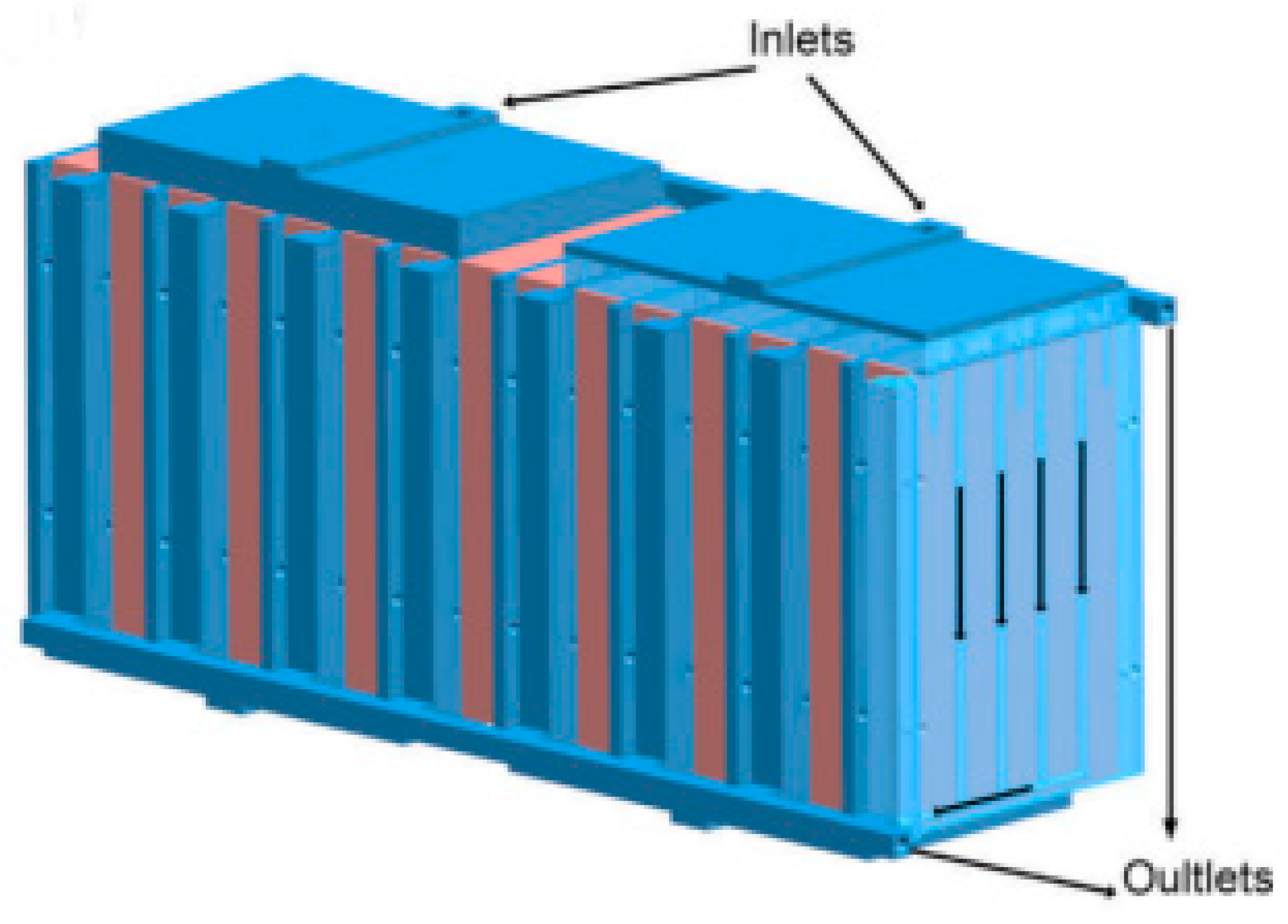
In this study, Ren et al. [59] studied a multichannel flat tube (MCFT)-based bottom liquid cooling (BLC) TMS (Figure 15). By comparing trials with the passive cooling approach, the temperature distribution of the battery module under the BLC method was examined. The impact of cold water flow rate and cold water inlet temperature variation on the effectiveness of thermal management was then investigated. The BLC TMS based on MCFT could successfully lower the temperature rise of the battery module without significantly lowering the temperature uniformity of the module. The battery module’s thermal management capabilities were only marginally impacted by the increase in cold water flow rate; the change in the module’s maximum temperature was only 1.4%. However, the thermal management capabilities of the battery module were significantly impacted by changes in the cold water inlet temperature. By lowering the cold water inlet temperature, the temperature of the battery module might be kept below 45 °C, but the temperature differences between the battery and module levels rose by 48.9% and 61.6%, respectively.
5. Immersion or Direct Cooling
Direct or immersive liquid cooling has recently gained much interest in electronic gadgets and the EV industry [23,60]. With this arrangement, the battery directly touches the cell by being submerged in a non-conductive dielectric fluid (Figure 16).
Fluids such as oils of hydrocarbons and silicone and fluorinated hydrocarbons were considered potential dielectric fluids. This unusual cooling method has several benefits. First, immersion cooling could provide the most preferred temperature homogeneity for pack and cell among all cooling techniques. The reason is that all the surfaces are sunk in the fluid, generating an even thermal transport path consisting of a large heat capacity for heat expulsion. This uninterrupted direct connection with the surfaces of the cell subsequently decreases the thermal contact resistances encountered in indirect techniques of cooling [23]. System complexity is reduced, and system design is simplified by immersion cooling [60]. Additionally, some of the dielectric fluids inhibit flames as well. So, the suppression of thermal runaways is a frequent phenomenon in immersion cooling, which subsequently improves the LIB pack’s safety.
5.1. Working Fluid
A system consisting of direct liquid cooling and air-cooling with 48 cells was thermally modeled by Nelson et al. [62]. Compared with air cooling, which showed a 5.3 °C temperature rise for initial load conditions, the results demonstrated that direct cooling using silicone oil delivered more excellent heat absorption with a cell temperature surge of only 2.5 °C. Karimi et al. [63,64] found a similar finding when comparing the thermal performance of direct silicone oil cooling and air cooling. A comprehensive comparison of single-cell simulation for three separate TMSs, i.e., thermal management systems, incorporating air cooling, indirect water/glycol jacket cooling, and direct mineral oil cooling, was carried out by Kim and Pesaran [65]. For smaller widths of cooling channels and larger flow rates, natural cooling showed the least temperature differential at the cell surface and the most excellent heat transfer coefficient among the three cooling techniques. A pressurized saturated liquid ammonia was one of the working fluids researchers suggested in addition to water/glycol systems. Al-Zareer et al. [66] demonstrated that a pressure of 9.0 bar is sufficient to keep the battery temperature below 40 °C for high power charging and discharging cycles at a rate of 7.5C, even though this liquid only covered 5% of the cell surface. A water cooling system was created by Pendergast et al. [67] for a battery module that used 18,650 cells encased in aluminum. Although the complexity and running expense increased, it was seen that the liquid cooling technology was as much as 3500 times more efficient than the air cooling. Additionally, the parasitic load dropped by 40% [68].
5.2. Parasitic Power
For any BTMS, the efficacy of the entire system must be considered. A slender battery module consisting of small gaps consumed lower parasitic power than a wider gap because of the low flow rate of coolant. In contrast, the cell-to-cell temperature variation across the module with large holes could be reduced, according to research by Park et al. [69], who designed a model of cylindrical cells for immersion cooling. They discovered that air cooling used more parasitic power than immersive cooling, particularly for heavy battery loads. A cooling simulation on a battery module with 21,700 cells found that direct air cooling and a dielectric coolant produced the battery system’s lowest temperature differential. The drawbacks of air cooling were the parasitic power requirement, insufficient heat capacity, and difficult flow control. Hence, it was determined that immersion cooling using dielectric fluid had the best cooling performance. However, its disadvantages included the increased difficulty and expense of condensing evaporated vapor, the more considerable pumping losses in high-viscosity fluids, the increased cost of the liquid, problems with the compatibility of materials, and an increase in fluid weight.
Even with these difficulties, immersion cooling has much potential as a direct cooling technique for BTMSs; moreover, there still needs to be an agreement on the kind of system and fluid to be employed.
5.3. Heat Transfer Fluid
This technique utilized a dielectric heat transfer fluid (HTF) to reduce the battery temperature more quickly and compactly than the air-cooling-based BTMS [70]. The HTF had a greater heat transfer coefficient, including greater thermal conductivity, lesser viscosity, and lower density, and was not allowed to react with battery material. In BTMS applications, water and mineral/silicone oils were typically employed. Due to their effective thermal conduction, liquified metals, nanofluids, and boiling liquids were increasingly used as heat transfer media in BTMSs [60]. Glycol was used with water as a heat transfer fluid during colder climates to prevent water from freezing due to lower surrounding temperatures [71]. According to Pesaran [72], the comparatively slender layer of the boundary caused oil to transmit heat at a rate significantly higher than air, although the mass flow rate was the same. Yet, there were large pressure drops and increased pumping power due to the oil’s higher viscosity. Hence, choosing the ideal oil mass flow rate was crucial. The working of the BTMS under air cooling as well as liquid cooling using mineral oil was examined by Chen et al. [73]. The researchers discovered that the BTMS consisting of the mineral oil cooling approach performed better than the air-cooling system. While choosing a liquid cooling system, the complete size and mass of the battery package, which was fairly heavy due to the thick mineral oil, should also be considered. To study the effectiveness of commercial-sized BTMSs with high-power lithium-ion cells under various operating situations employing silicon oil, silicon water, and air as the HTF, Karimi and Dehghan [63] created a thermal model, as shown in Figure 17. They discovered that the HTF inlet/outlet design had a critical influence on the performance of the pack, regardless of the cooling medium. Using silicon and water could be preferable since air as a heat transfer fluid was insufficient to maintain the desired battery temperature range at high discharge rates (5C).
5.4. Configurations
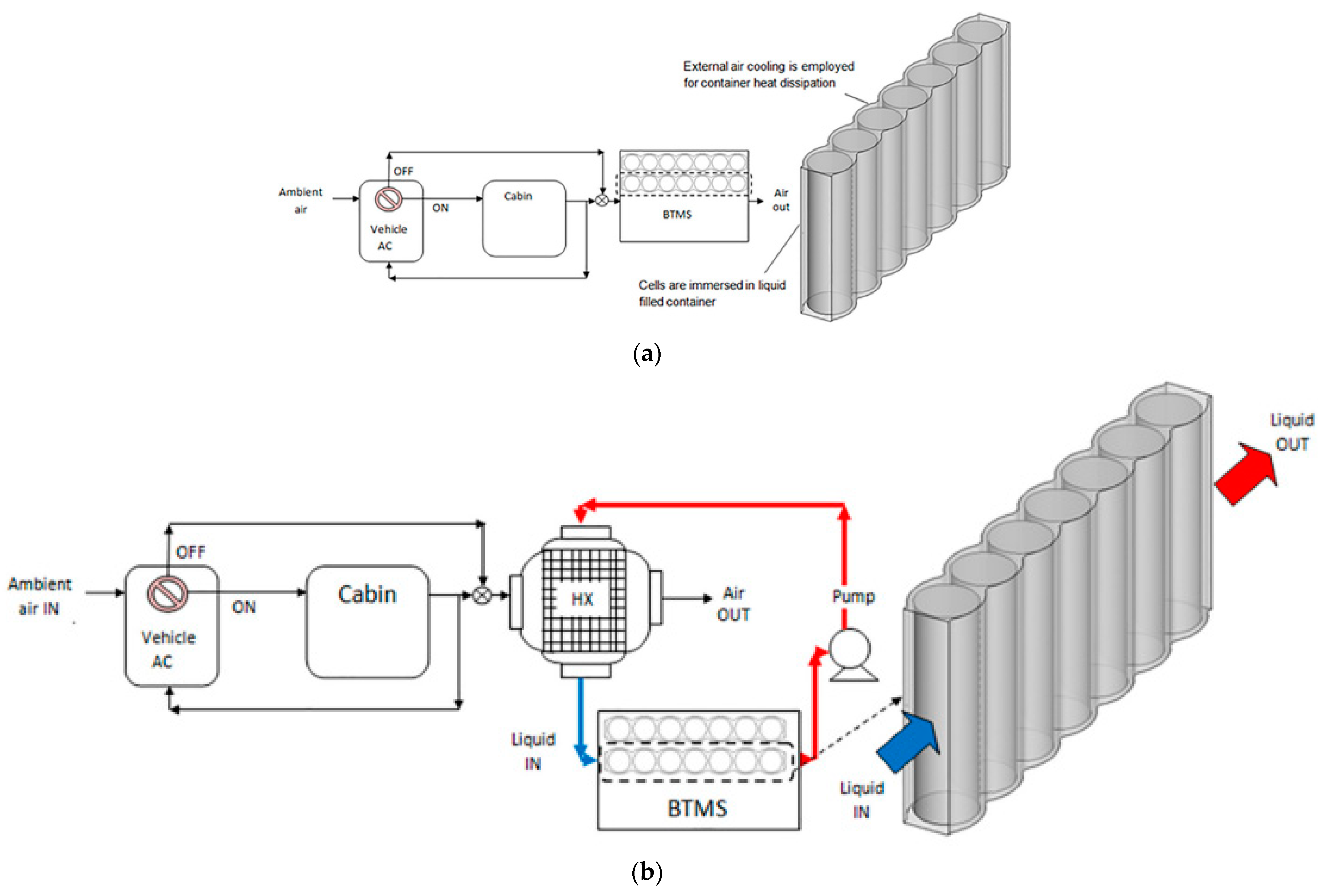
Park and Jung [69] analyzed the LIB’s cooling capabilities for various cell configurations and heat transfer fluid (HTF) types. They discovered that liquid cooling was optimal for narrow battery designs and that air cooling was best for larger ones with tiny cell-to-cell gaps. When the discharge rate was high, the air-cooled system used more electricity than the liquid-cooled system. In distinct scenarios, two BTMSs were considered: one liquid circulation BTMS (LcBS) and one liquid-filled BTMS (LfBS), as illustrated in Figure 18.
Jilte et al. [74] published the simulation findings for liquids utilizing water and 0.4 vol.% Al2O3 nanofluid. They discovered that, without a liquid circulation system and low ambient temperatures, the LfBS would be a superior solution for batteries with moderate discharge rates (2C). Additionally, the LcBS kept the battery surface’s temperature within a desirable range for a greater discharge rate. The heat received by the heat transfer fluid was rejected by the air conditioner’s recirculated air or the outside air. While using LcBS rather than LfBS, the battery performance was improved because of the uniform temperature distribution, which was a crucial component. Further, Al2O3 utilization could dramatically lower the surface temperature of the battery at increased discharging rates for these two cases.
5.5. Nanoparticles
In contrast to water, silicon oil had a higher viscosity, which increased power consumption. Since the thermal conductivity of oils and water was low, direct-contact liquid cooling systems were restricted. However, adding nanoparticles having higher thermal conductivities as compared to base fluid could enhance the efficiency of the liquid-cooled BTMS [75]. By adding different concentrations of graphene nanoplatelets (GnP), Sidney et al. [76] assessed water’s thermal conductivity. They noticed that adding 0.5 vol.% of GnP enhanced the water’s thermal conductivity by up to 24%. Selvam et al. [77] found a similar rise in glycol by 21% with 0.5 vol.%. Huo and Rao [78] used water and Al2O3-water nanofluid to model the thermal characteristics of the battery systems, having one cell and five cells, with a liquid cooling BTMS. Due to the increased cooling efficiency as compared to water-cooled BTMS, they discovered that adding 0.04 vol.% of Al2O3 decreased the mean temperature of cells by 7%.
5.6. Boiling Fluid
The drawback of the direct cooling BTMS was the extra power consumption required for HTF pumping. Batteries were inserted straight into the dormant boiling HTF fluid to eliminate the need for pumping power. In this procedure, the phase change fluid expelled the heat to the other medium after the heat was absorbed from the battery surface by the boiling fluid using latent heat of vaporization [66]. This process’s vaporizing boiling heat transfer fluid temperatures should be around the ideal temperature of the battery surface. Al-Zareer created a BTMS using a boiling fluid to transfer heat using ammonia [66] and liquid propane [79]. Just 5% of the surface was filled with liquid ammonia and propane, which was put in at a pressure of about 8.5 bars. Although there was a rise in the average temperature at the surface, it was found that the pressure rise decreased the temperature differential across the surface. They discovered that the application of a BTMS based on ammonia and propane provided greater cooling regulation of the battery surface temperature and could keep it beneath 40 °C under very high discharging or charging rates, e.g., 7.5C. A boiling battery cooling method was created by Hirano et al. [80], employing hydrofluoric ether (Novec-7000) and perfluoro ketone (Novec-649) as the medium for heat transfer. Novec-7000 and Novec-649 had boiling points of 34 °C and 49 °C. High discharging or charging rates of 10 C and 20 C were used in the investigation. The two BTMSs for boiling liquid and air cooling at 10 C discharging/charging rates were compared. It was noticed that when cells were cooled with air, their temperatures increased to between 80 °C and 90 °C, whereas when cells were completely submerged in Novec-7000 or Novec-64, respectively, their temperatures remained at 35 °C and 50 °C. It was also discovered that the boiling point of the chosen fluid was a factor in the steady temperature of the cell surface. The ability of a boiling process to homogenize and bring down the temperature of the batteries was investigated by Gils et al. [81]. It was discovered that Novec7000, which was investigated as a cooling fluid, did not carry electricity; as a result, the battery was directly used with any sealing material. Due to a greater heat transfer rate from solid to liquid, Novec-7000 demonstrated better cooling capability than air. The results showed that there was a 0.7 °C temperature differential between the negative and positive electrodes in the absence of boiling, which disappeared entirely after the battery’s surrounding liquid began to boil. A new cooling method for BTMSs was proposed by An et al. [39] which used dielectric hydrofluoroether boiling in a mini-channel. When boiling heat transfer occurred, the results showed that small channel cooling retained the cell temperature at about 40 °C. Boiling heat transfer provided the advantage of lowering the battery’s maximum surface temperature by 4 °C.
Wang created a unique thermal management system for EV battery packs, and Wu [82] employed the dielectric refrigerant HFE-7000, which was non-flammable. Additionally, they contrasted the experimental outcomes with analytical data. The findings demonstrated that using refrigerant improved the heat transfer capacity of refrigerants by lowering thermal resistance due to boiling. In addition, at a discharging rate of 5C, the cell temperature was maintained between 0 °C and 3.7 °C. The findings illustrate that the maximum battery surface could be kept at 35 °C for a 5C discharging rate using HFE-7000 at 0.3 m/s flow velocity.
6. Conclusions
Liquid cooling, with an appropriate configuration, can be up to 3500 times more efficient than air cooling. This conclusion is in a similar vein to previously conducted studies, which suggest that despite requiring auxiliary indirect heat transfer devices, water cooling is more effective than air cooling. The saving in parasitic power consumption can be obtained by up to 40%. Indirect cooling technologies, such as cold plates, discrete tubes, serpentine tubes, etc., have been explored significantly. Adding to the findings of previous studies, which concluded that a proper dose of nanoparticles can be added to the cooling system to improve cooling performance, it can be inferred that adding nanoparticles can help increase the thermal conduction in the base coolant. However, it is found that it does not affect the temperature of the battery pack significantly. For parallel cold plate liquid cooling, the peak temperature attained by the battery pack, Tmax, decreased when the flow channels were increased in number, and the rate of mass inflow was greater. As per numerical analysis and simulation, liquid metal is an efficient cooling agent for battery thermal management under demanding and abusive settings for EVs. With liquid metal as a coolant, the weight of liquified metal is its only drawback, which makes the whole system bulkier.
In a system using variable contact resistance, the maximum temperature of the aluminum block lowered to the same temperature as that when the length was 24 mm when contact and variable surfaces were compared, but a lighter system was required to achieve a more uniform temperature. It was advised against improving cooling performance just by raising velocity because doing so increased pump power consumption.
For direct/immersive cooling, disadvantages included the increased complexity and expense of condensing evaporated vapor, considerable pumping losses in high-viscosity fluids, high cost of the liquid, problems with material compatibility, and an increase in fluid weight. Even with these difficulties, immersion cooling had much potential as a direct cooling technique for BTMSs; moreover, there still needs to be an agreement on the kind of system and fluid to be employed. Immersion/direct cooling holds sufficient caliber to be employed as a liquid cooling method. Indirect cooling methods, such as the cooling plate technique, were found in previous studies to be suitable for prismatic and pouch cells. Additionally, liquid jacket cooling is recommended for cylindrical cells. However, this study found that the direct contact mechanism of coolant and the cell surface provides an added advantage to direct cooling compared to indirect cooling. Direct cooling can provide substantial relief from the threat of thermal runaway. Coolants appropriate for direct cooling include mineral oils, hydrocarbons, silicone oils, esters, and a mixture of water and glycol. However, further research is required to study the lifetime impact of coolant on the immersed battery cells. Serpentine liquid cooling has been patented by the electric vehicle giant Tesla Inc and has proven effective. Direct cooling techniques need to be further explored with similar innovative efforts to alleviate the limitations of liquid coolants concerning their weight, pumping losses, increased complexity, and expenses.
Author Contributions
Conceptualization, A. and A.K.; methodology, A.; formal analysis, A.; investigation, A. and A.K.; writing—original draft preparation, A.; writing—review and editing, A.K.; visualization, A.K.; supervision, A.K. All authors have read and agreed to the published version of the manuscript.
Funding
This research received no external funding.
Data Availability Statement
Not applicable.
Acknowledgments
The first author would like to gratefully acknowledge the support of the Centre for Energy and Environment, Delhi Technological University, provided during the manuscript preparation and literature survey.
Conflicts of Interest
The authors declare no conflict of interest.
References
- Zhou, J.; Mao, X.Q.; Hu, T.; Zeng, A.; Xing, Y.K.; Corsetti, G. Implications of the 11th and 12th Five-Year Plans for Energy Conservation and CO2 and Air Pollutants Reduction: A Case Study from the City of Urumqi, China. J. Clean. Prod. 2016, 112, 1767–1777. [Google Scholar] [CrossRef]
- Tursun, H.; Li, Z.; Liu, R.; Li, Y.; Wang, X. Contribution Weight of Engineering Technology on Pollutant Emission Reduction Based on IPAT and LMDI Methods. Clean. Technol. Environ. Policy 2015, 17, 225–235. [Google Scholar] [CrossRef]
- O’Mahony, T. Decomposition of Ireland’s Carbon Emissions from 1990 to 2010: An Extended Kaya Identity. Energy Policy 2013, 59, 573–581. [Google Scholar] [CrossRef] [Green Version]
- Nam, K.M.; Waugh, C.J.; Paltsev, S.; Reilly, J.M.; Karplus, V.J. Carbon Co-Benefits of Tighter SO2 and NOx Regulations in China. Glob. Environ. Chang. 2013, 23, 1648–1661. [Google Scholar] [CrossRef]
- Alajmi, R.G. Factors That Impact Greenhouse Gas Emissions in Saudi Arabia: Decomposition Analysis Using LMDI. Energy Policy 2021, 156, 112454. [Google Scholar] [CrossRef]
- Gu, S.; Fu, B.; Thriveni, T.; Fujita, T.; Ahn, J.W. Coupled LMDI and System Dynamics Model for Estimating Urban CO2 Emission Mitigation Potential in Shanghai, China. J. Clean. Prod. 2019, 240, 118034. [Google Scholar] [CrossRef]
- Shahzad, M.W.; Burhan, M.; Ang, L.; Ng, K.C. Energy-Water-Environment Nexus Underpinning Future Desalination Sustainability. Desalination 2017, 413, 52–64. [Google Scholar] [CrossRef]
- Hema, R.; Venkatarangan, M.J. Adoption of EV: Landscape of EV and Opportunities for India. Meas. Sens. 2022, 24, 100596. [Google Scholar] [CrossRef]
- Wang, J.; Li, Y.; Zhang, Y. Research on Carbon Emissions of Road Traffic in Chengdu City Based on a LEAP Model. Sustainability 2022, 14, 5625. [Google Scholar] [CrossRef]
- Gao, R.; Fan, Z.; Liu, S. A Gradient Channel-Based Novel Design of Liquid-Cooled Battery Thermal Management System for Thermal Uniformity Improvement. J. Energy Storage 2022, 48, 104014. [Google Scholar] [CrossRef]
- Hekmat, S.; Bamdezh, M.A.; Molaeimanesh, G.R. Hybrid Thermal Management for Achieving Extremely Uniform Temperature Distribution in a Lithium Battery Module with Phase Change Material and Liquid Cooling Channels. J. Energy Storage 2022, 50, 104272. [Google Scholar] [CrossRef]
- Ling, Z.; Wang, F.; Fang, X.; Gao, X.; Zhang, Z. A Hybrid Thermal Management System for Lithium Ion Batteries Combining Phase Change Materials with Forced-Air Cooling. Appl. Energy 2015, 148, 403–409. [Google Scholar] [CrossRef] [Green Version]
- Qin, P.; Liao, M.; Zhang, D.; Liu, Y.; Sun, J.; Wang, Q. Experimental and Numerical Study on a Novel Hybrid Battery Thermal Management System Integrated Forced-Air Convection and Phase Change Material. Energy Convers. Manag. 2019, 195, 1371–1381. [Google Scholar] [CrossRef]
- Greco, A.; Jiang, X.; Cao, D. An Investigation of Lithium-Ion Battery Thermal Management Using Paraffin/Porous-Graphite-Matrix Composite. J. Power Sources 2015, 278, 50–68. [Google Scholar] [CrossRef]
- Rao, Z.; Qian, Z.; Kuang, Y.; Li, Y. Thermal Performance of Liquid Cooling Based Thermal Management System for Cylindrical Lithium-Ion Battery Module with Variable Contact Surface. Appl. Therm. Eng. 2017, 123, 1514–1522. [Google Scholar] [CrossRef]
- Jiang, Z.Y.; Qu, Z.G. Lithium–Ion Battery Thermal Management Using Heat Pipe and Phase Change Material during Discharge–Charge Cycle: A Comprehensive Numerical Study. Appl. Energy 2019, 242, 378–392. [Google Scholar] [CrossRef]
- Pesaran, A.A.; Keyser, M.; Kim, G.; Santhanagopalan, S.; Smith, K. Tools for Designing Thermal Management of Batteries in Electric Drive Vehicles Battery Temperature in XEVs. Adv. Automot. Batter. Conf. 2013, 13, 104–116. [Google Scholar] [CrossRef] [Green Version]
- Singirikonda, S.; Obulesu, Y.P. Adaptive Secondary Loop Liquid Cooling with Refrigerant Cabin Active Thermal Management System for Electric Vehicle. J. Energy Storage 2022, 50, 104624. [Google Scholar] [CrossRef]
- Tete, P.R.; Gupta, M.M.; Joshi, S.S. Developments in Battery Thermal Management Systems for Electric Vehicles: A Technical Review. J. Energy Storage 2021, 35, 102255. [Google Scholar] [CrossRef]
- Tang, X.; Guo, Q.; Li, M.; Wei, C.; Pan, Z.; Wang, Y. Performance Analysis on Liquid-Cooled Battery Thermal Management for Electric Vehicles Based on Machine Learning. J. Power Sources 2021, 494, 229727. [Google Scholar] [CrossRef]
- Tang, Z.; Liu, Z.; Li, J.; Cheng, J. A Lightweight Liquid Cooling Thermal Management Structure for Prismatic Batteries. J. Energy Storage 2021, 42, 103078. [Google Scholar] [CrossRef]
- Wang, H.; Tao, T.; Xu, J.; Mei, X.; Liu, X.; Gou, P. Cooling Capacity of a Novel Modular Liquid-Cooled Battery Thermal Management System for Cylindrical Lithium Ion Batteries. Appl. Therm. Eng. 2020, 178, 115591. [Google Scholar] [CrossRef]
- Li, W.; Li, L.; Cui, W.; Guo, M. Experimental Investigation on the Thermal Performance of Vapor Chamber in a Compound Liquid Cooling System. Int. J. Heat Mass Transf. 2021, 170, 121026. [Google Scholar] [CrossRef]
- Huo, Y.; Rao, Z.; Liu, X.; Zhao, J. Investigation of Power Battery Thermal Management by Using Mini-Channel Cold Plate. Energy Convers. Manag. 2015, 89, 387–395. [Google Scholar] [CrossRef]
- Li, W.; Zhuang, X.; Xu, X. Numerical Study of a Novel Battery Thermal Management System for a Prismatic Li-Ion Battery Module. Energy Procedia 2019, 158, 4441–4446. [Google Scholar] [CrossRef]
- Xie, J.; Xie, Y.; Yuan, C. Numerical Study of Heat Transfer Enhancement Using Vortex Generator for Thermal Management of Lithium Ion Battery. Int. J. Heat Mass Transf. 2019, 129, 1184–1193. [Google Scholar] [CrossRef]
- Zhao, J.; Rao, Z.; Li, Y. Thermal Performance of Mini-Channel Liquid Cooled Cylinder Based Battery Thermal Management for Cylindrical Lithium-Ion Power Battery. Energy Convers. Manag. 2015, 103, 157–165. [Google Scholar] [CrossRef]
- Qian, Z.; Li, Y.; Rao, Z. Thermal Performance of Lithium-Ion Battery Thermal Management System by Using Mini-Channel Cooling. Energy Convers. Manag. 2016, 126, 622–631. [Google Scholar] [CrossRef]
- Huang, Y.; Mei, P.; Lu, Y.; Huang, R.; Yu, X.; Chen, Z.; Roskilly, A.P. A Novel Approach for Lithium-Ion Battery Thermal Management with Streamline Shape Mini Channel Cooling Plates. Appl. Therm. Eng. 2019, 157, 33. [Google Scholar] [CrossRef]
- Jiaqiang, E.; Han, D.; Qiu, A.; Zhu, H.; Deng, Y.; Chen, J.; Zhao, X.; Zuo, W.; Wang, H.; Chen, J.; et al. Orthogonal Experimental Design of Liquid-Cooling Structure on the Cooling Effect of a Liquid-Cooled Battery Thermal Management System. Appl. Therm. Eng. 2018, 132, 508–520. [Google Scholar] [CrossRef]
- Zhao, J.; Rao, Z.; Liu, C.; Li, Y. Experiment Study of Oscillating Heat Pipe and Phase Change Materials Coupled for Thermal Energy Storage and Thermal Management. Int. J. Heat Mass Transf. 2016, 99, 252–260. [Google Scholar] [CrossRef]
- Malik, M.; Dincer, I.; Rosen, M.A.; Mathew, M.; Fowler, M. Thermal and Electrical Performance Evaluations of Series Connected Li-Ion Batteries in a Pack with Liquid Cooling. Appl. Therm. Eng. 2018, 129, 472–481. [Google Scholar] [CrossRef]
- Yang, X.H.; Tan, S.C.; Liu, J. Thermal Management of Li-Ion Battery with Liquid Metal. Energy Convers. Manag. 2016, 117, 577–585. [Google Scholar] [CrossRef]
- Park, S.; Jang, D.S.; Lee, D.C.; Hong, S.H.; Kim, Y. Simulation on Cooling Performance Characteristics of a Refrigerant-Cooled Active Thermal Management System for Lithium Ion Batteries. Int. J. Heat Mass Transf. 2019, 135, 131–141. [Google Scholar] [CrossRef]
- Xu, X.; Li, W.; Xu, B.; Qin, J. Numerical Study on a Water Cooling System for Prismatic LiFePO4 Batteries at Abused Operating Conditions. Appl. Energy 2019, 250, 404–412. [Google Scholar] [CrossRef]
- Chung, Y.; Kim, M.S. Thermal Analysis and Pack Level Design of Battery Thermal Management System with Liquid Cooling for Electric Vehicles. Energy Convers. Manag. 2019, 196, 105–116. [Google Scholar] [CrossRef]
- Tang, A.; Li, J.; Lou, L.; Shan, C.; Yuan, X. Optimization Design and Numerical Study on Water Cooling Structure for Power Lithium Battery Pack. Appl. Therm. Eng. 2019, 159, 113760. [Google Scholar] [CrossRef]
- Jin, L.W.; Lee, P.S.; Kong, X.X.; Fan, Y.; Chou, S.K. Ultra-Thin Minichannel LCP for EV Battery Thermal Management. Appl. Energy 2014, 113, 1786–1794. [Google Scholar] [CrossRef]
- An, Z.; Jia, L.; Li, X.; Ding, Y. Experimental Investigation on Lithium-Ion Battery Thermal Management Based on Flow Boiling in Mini-Channel. Appl. Therm. Eng. 2017, 117, 534–543. [Google Scholar] [CrossRef]
- Mondal, B.; Lopez, C.F.; Mukherjee, P.P. Exploring the Efficacy of Nanofluids for Lithium-Ion Battery Thermal Management. Int. J. Heat Mass Transf. 2017, 112, 779–794. [Google Scholar] [CrossRef]
- Panchal, S.; Khasow, R.; Dincer, I.; Agelin-Chaab, M.; Fraser, R.; Fowler, M. Thermal Design and Simulation of Mini-Channel Cold Plate for Water Cooled Large Sized Prismatic Lithium-Ion Battery. Appl. Therm. Eng. 2017, 122, 80–90. [Google Scholar] [CrossRef]
- Panchal, S.; Dincer, I.; Agelin-Chaab, M.; Fraser, R.; Fowler, M. Thermal Modeling and Validation of Temperature Distributions in a Prismatic Lithium-Ion Battery at Different Discharge Rates and Varying Boundary Conditions. Appl. Therm. Eng. 2016, 96, 190–199. [Google Scholar] [CrossRef]
- Jrckb, P.; Ponangi, B.R. Design and Analysis of Cold Plate for Electric Vehicle Battery Pack. In Proceedings of the 25th National and 3rd International ISHMT-ASTFE Heat and Mass Transfer Conference (IHMTC-2019), Roorkee, India, 28–31 December 2019; Volume 1260, pp. 751–756. [Google Scholar] [CrossRef]
- Cao, W.; Zhao, C.; Wang, Y.; Dong, T.; Jiang, F. Thermal Modeling of Full-Size-Scale Cylindrical Battery Pack Cooled by Channeled Liquid Flow. Int. J. Heat Mass Transf. 2019, 138, 1178–1187. [Google Scholar] [CrossRef]
- Li, Y.; Zhou, Z.; Wu, W.T. Three-Dimensional Thermal Modeling of Li-Ion Battery Cell and 50 V Li-Ion Battery Pack Cooled by Mini-Channel Cold Plate. Appl. Therm. Eng. 2019, 147, 829–840. [Google Scholar] [CrossRef]
- Sheng, L.; Su, L.; Zhang, H.; Li, K.; Fang, Y.; Ye, W.; Fang, Y. Numerical Investigation on a Lithium Ion Battery Thermal Management Utilizing a Serpentine-Channel Liquid Cooling Plate Exchanger. Int. J. Heat Mass Transf. 2019, 141, 658–668. [Google Scholar] [CrossRef]
- Deng, T.; Zhang, G.; Ran, Y.; Liu, P. Thermal Performance of Lithium Ion Battery Pack by Using Cold Plate. Appl. Therm. Eng. 2019, 160, 114088. [Google Scholar] [CrossRef]
- Deng, T.; Zhang, G.; Ran, Y. Study on Thermal Management of Rectangular Li-Ion Battery with Serpentine-Channel Cold Plate. Int. J. Heat Mass Transf. 2018, 125, 143–152. [Google Scholar] [CrossRef]
- Zhao, C.; Sousa, A.C.M.; Jiang, F. Minimization of Thermal Non-Uniformity in Lithium-Ion Battery Pack Cooled by Channeled Liquid Flow. Int. J. Heat Mass Transf. 2019, 129, 660–670. [Google Scholar] [CrossRef]
- Jiaqiang, E.; Xu, S.; Deng, Y.; Zhu, H.; Zuo, W.; Wang, H.; Chen, J.; Peng, Q.; Zhang, Z. Investigation on Thermal Performance and Pressure Loss of the Fluid Cold-Plate Used in Thermal Management System of the Battery Pack. Appl. Therm. Eng. 2018, 145, 552–568. [Google Scholar] [CrossRef]
- Li, P.; Zhao, J.; Zhou, S.; Duan, J.; Li, X.; Zhang, H.; Yuan, J. Design and Optimization of a Liquid Cooling Thermal Management System with Flow Distributors and Spiral Channel Cooling Plates for Lithium-Ion Batteries. Energies 2023, 16, 2196. [Google Scholar] [CrossRef]
- An, Z.; Shah, K.; Jia, L.; Ma, Y. A Parametric Study for Optimization of Minichannel Based Battery Thermal Management System. Appl. Therm. Eng. 2019, 154, 593–601. [Google Scholar] [CrossRef] [Green Version]
- Li, X.; Zhou, D.; Zhang, G.; Wang, C.; Lin, R.; Zhong, Z. Experimental Investigation of the Thermal Performance of Silicon Cold Plate for Battery Thermal Management System. Appl. Therm. Eng. 2019, 155, 331–340. [Google Scholar] [CrossRef]
- Lv, Y.; Zhou, D.; Yang, X.; Liu, X.; Li, X.; Zhang, G. Experimental Investigation on a Novel Liquid-Cooling Strategy by Coupling with Graphene-Modified Silica Gel for the Thermal Management of Cylindrical Battery. Appl. Therm. Eng. 2019, 159, 113885. [Google Scholar] [CrossRef]
- Zhou, H.; Zhou, F.; Zhang, Q.; Wang, Q.; Song, Z. Thermal Management of Cylindrical Lithium-Ion Battery Based on a Liquid Cooling Method with Half-Helical Duct. Appl. Therm. Eng. 2019, 162, 114257. [Google Scholar] [CrossRef]
- Li, K.; Yan, J.; Chen, H.; Wang, Q. Water Cooling Based Strategy for Lithium Ion Battery Pack Dynamic Cycling for Thermal Management System. Appl. Therm. Eng. 2018, 132, 575–585. [Google Scholar] [CrossRef]
- Lan, C.; Xu, J.; Qiao, Y.; Ma, Y. Thermal Management for High Power Lithium-Ion Battery by Minichannel Aluminum Tubes. Appl. Therm. Eng. 2016, 101, 284–292. [Google Scholar] [CrossRef] [Green Version]
- Basu, S.; Hariharan, K.S.; Kolake, S.M.; Song, T.; Sohn, D.K.; Yeo, T. Coupled Electrochemical Thermal Modelling of a Novel Li-Ion Battery Pack Thermal Management System. Appl. Energy 2016, 181, 1–13. [Google Scholar] [CrossRef]
- Ren, R.; Zhao, Y.; Diao, Y.; Liang, L. Experimental Study on the Bottom Liquid Cooling Thermal Management System for Lithium-Ion Battery Based on Multichannel Flat Tube. Appl. Therm. Eng. 2023, 219, 119636. [Google Scholar] [CrossRef]
- Deng, Y.; Feng, C.E.J.; Zhu, H.; Chen, J.; Wen, M.; Yin, H. Effects of Different Coolants and Cooling Strategies on the Cooling Performance of the Power Lithium Ion Battery System: A Review. Appl. Therm. Eng. 2018, 142, 10–29. [Google Scholar] [CrossRef]
- Offer, G.; Patel, Y.; Hales, A.; Bravo Diaz, L.; Marzook, M. Cool Metric for Lithium-Ion Batteries Could Spur Progress. Nature 2020, 582, 485–487. [Google Scholar] [CrossRef] [PubMed]
- Nelson, P.; Dees, D.; Amine, K.; Henriksen, G. Modeling Thermal Management of Lithium-Ion PNGV Batteries. J. Power Sources 2002, 110, 349–356. [Google Scholar] [CrossRef]
- Karimi, G.; Dehghan, A.R. Thermal Analysis of High-Power Lithium-Ion Battery Packs Using Flow Network Approach. Int. J. Energy Res. 2014, 38, 1793–1811. [Google Scholar] [CrossRef]
- Karimi, G.; Li, X. Thermal Management of Lithium-Ion Batteries for Electric Vehicles. Int. J. Energy Res. 2013, 37, 13–24. [Google Scholar] [CrossRef]
- Kim, G.H.; Pesaran, A. Battery Thermal Management Design Modeling. World Electr. Veh. J. 2007, 1, 126–133. [Google Scholar] [CrossRef] [Green Version]
- Al-Zareer, M.; Dincer, I.; Rosen, M.A. Electrochemical Modeling and Performance Evaluation of a New Ammonia-Based Battery Thermal Management System for Electric and Hybrid Electric Vehicles. Electrochim. Acta 2017, 247, 171–182. [Google Scholar] [CrossRef]
- Pendergast, D.R.; Demauro, E.P.; Fletcher, M.; Stimson, E.; Mollendorf, J.C. A Rechargeable Lithium-Ion Battery Module for Underwater Use. J. Power Sources 2011, 196, 793–800. [Google Scholar] [CrossRef]
- Xia, G.; Cao, L.; Bi, G. A Review on Battery Thermal Management in Electric Vehicle Application. J. Power Sources 2017, 367, 90–105. [Google Scholar] [CrossRef]
- Park, S.; Jung, D. Battery Cell Arrangement and Heat Transfer Fluid Effects on the Parasitic Power Consumption and the Cell Temperature Distribution in a Hybrid Electric Vehicle. J. Power Sources 2013, 227, 191–198. [Google Scholar] [CrossRef]
- Saw, L.H.; Tay, A.A.O.; Zhang, L.W. Thermal Management of Lithium-Ion Battery Pack with Liquid Cooling. Annu. IEEE Semicond. Therm. Meas. Manag. Symp. 2015, 2015, 298–302. [Google Scholar] [CrossRef]
- Smith, J.; Hinterberger, M.; Hable, P.; Koehler, J. Simulative Method for Determining the Optimal Operating Conditions for a Cooling Plate for Lithium-Ion Battery Cell Modules. J. Power Sources 2014, 267, 784–792. [Google Scholar] [CrossRef]
- Ahmad, A. Pesaran Battery Thermal Management in EVs and HEVs: Issues and Solutions. Battery Man 2001, 43, 34–49. [Google Scholar]
- Chen, S.C.; Wan, C.C.; Wang, Y.Y. Thermal Analysis of Lithium-Ion Batteries. J. Power Sources 2005, 140, 111–124. [Google Scholar] [CrossRef]
- Jilte, R.D.; Kumar, R.; Ahmadi, M.H. Cooling Performance of Nanofluid Submerged vs. Nanofluid Circulated Battery Thermal Management Systems. J. Clean. Prod. 2019, 240, 118131. [Google Scholar] [CrossRef]
- Beheshti, A.; Shanbedi, M.; Heris, S.Z. Heat Transfer and Rheological Properties of Transformer Oil-Oxidized MWCNT Nanofluid. J. Therm. Anal. Calorim. 2014, 118, 1451–1460. [Google Scholar] [CrossRef]
- Sidney, S.; Dhasan, M.L.; Selvam, C.; Harish, S. Experimental Investigation of Freezing and Melting Characteristics of Graphene-Based Phase Change Nanocomposite for Cold Thermal Energy Storage Applications. Appl. Sci. 2019, 9, 1099. [Google Scholar] [CrossRef] [Green Version]
- Selvam, C.; Lal, D.M.; Harish, S. Thermal Conductivity Enhancement of Ethylene Glycol and Water with Graphene Nanoplatelets. Thermochim. Acta 2016, 642, 32–38. [Google Scholar] [CrossRef]
- Huo, Y.; Rao, Z. The Numerical Investigation of Nanofluid Based Cylinder Battery Thermal Management Using Lattice Boltzmann Method. Int. J. Heat Mass Transf. 2015, 91, 374–384. [Google Scholar] [CrossRef]
- Al-Zareer, M.; Dincer, I.; Rosen, M.A. Novel Thermal Management System Using Boiling Cooling for High-Powered Lithium-Ion Battery Packs for Hybrid Electric Vehicles. J. Power Sources 2017, 363, 291–303. [Google Scholar] [CrossRef]
- Hirano, H.; Tajima, T.; Hasegawa, T.; Sekiguchi, T.; Uchino, M. Boiling Liquid Battery Cooling for Electric Vehicle. In Proceedings of the 2014 IEEE Conference and Expo Transportation Electrification Asia-Pacific (ITEC Asia-Pacific), Beijing, China, 31 August–3 September 2014; pp. 1–4. [Google Scholar] [CrossRef]
- Van Gils, R.W.; Danilov, D.; Notten, P.H.L.; Speetjens, M.F.M.; Nijmeijer, H. Battery Thermal Management by Boiling Heat-Transfer. Energy Convers. Manag. 2014, 79, 9–17. [Google Scholar] [CrossRef]
- Wang, Y.F.; Wu, J.T. Thermal Performance Predictions for an HFE-7000 Direct Flow Boiling Cooled Battery Thermal Management System for Electric Vehicles. Energy Convers. Manag. 2020, 207, 112569. [Google Scholar] [CrossRef]
Figure 1.
Cooling system model: (a) Schematic of Li-ion battery pack; (b) Boundary condition of symmetry applied to the top and bottom surfaces [24].
Figure 1.
Cooling system model: (a) Schematic of Li-ion battery pack; (b) Boundary condition of symmetry applied to the top and bottom surfaces [24].

Figure 2.
Cylindrical Li-ion battery pack and computational domain: (a) Li-ion battery with liquid cooled cylinders; (b) Enlarged 1/4th part of battery unit and its relative dimensions [27].
Figure 2.
Cylindrical Li-ion battery pack and computational domain: (a) Li-ion battery with liquid cooled cylinders; (b) Enlarged 1/4th part of battery unit and its relative dimensions [27].

Figure 3.
Streamline-shaped BTMS [29].
Figure 3.
Streamline-shaped BTMS [29].
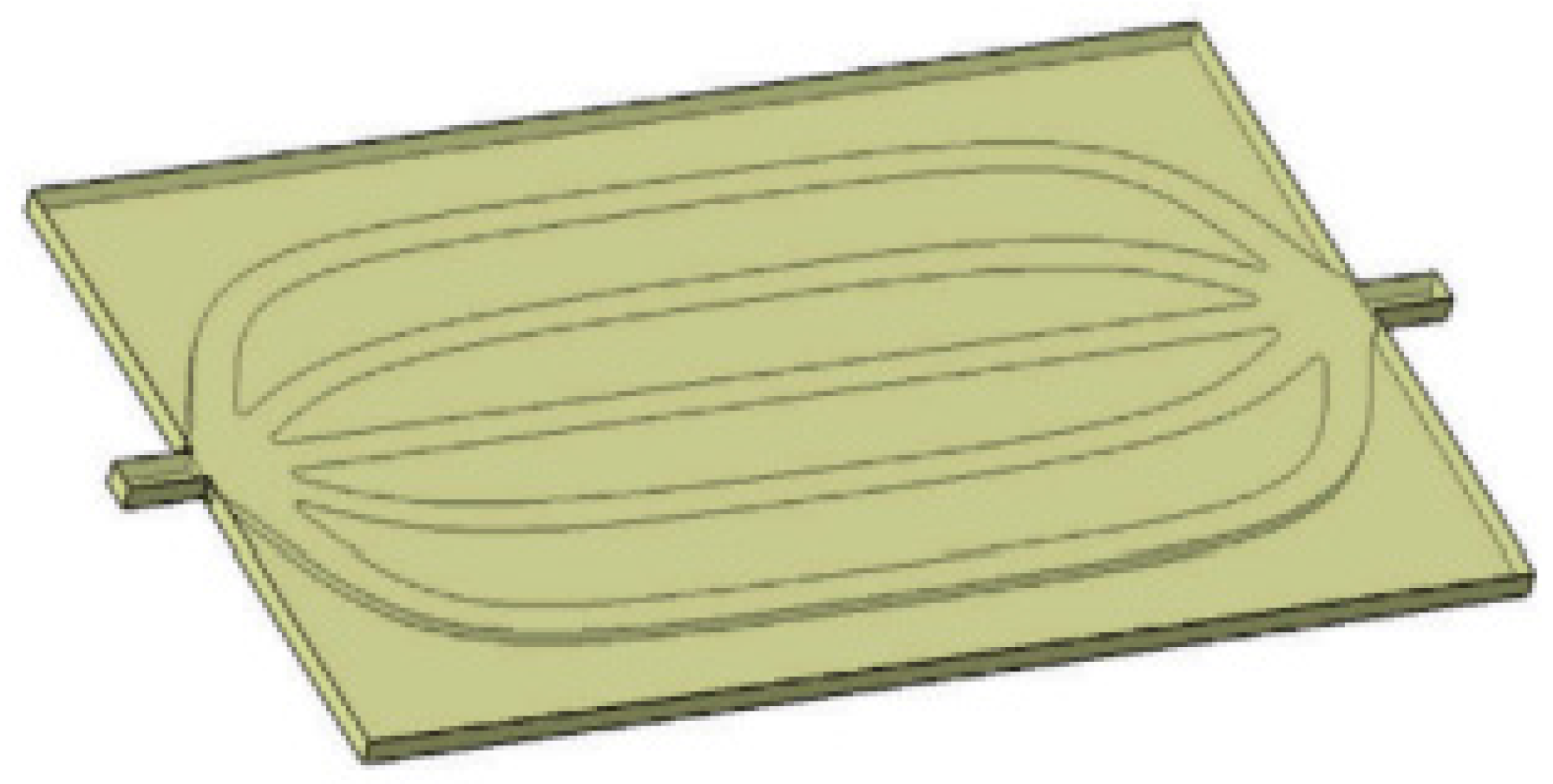
Figure 4.
Parallel mini-channel cold plate [35].
Figure 4.
Parallel mini-channel cold plate [35].

Figure 6.
U-tube channel [50].
Figure 6.
U-tube channel [50].
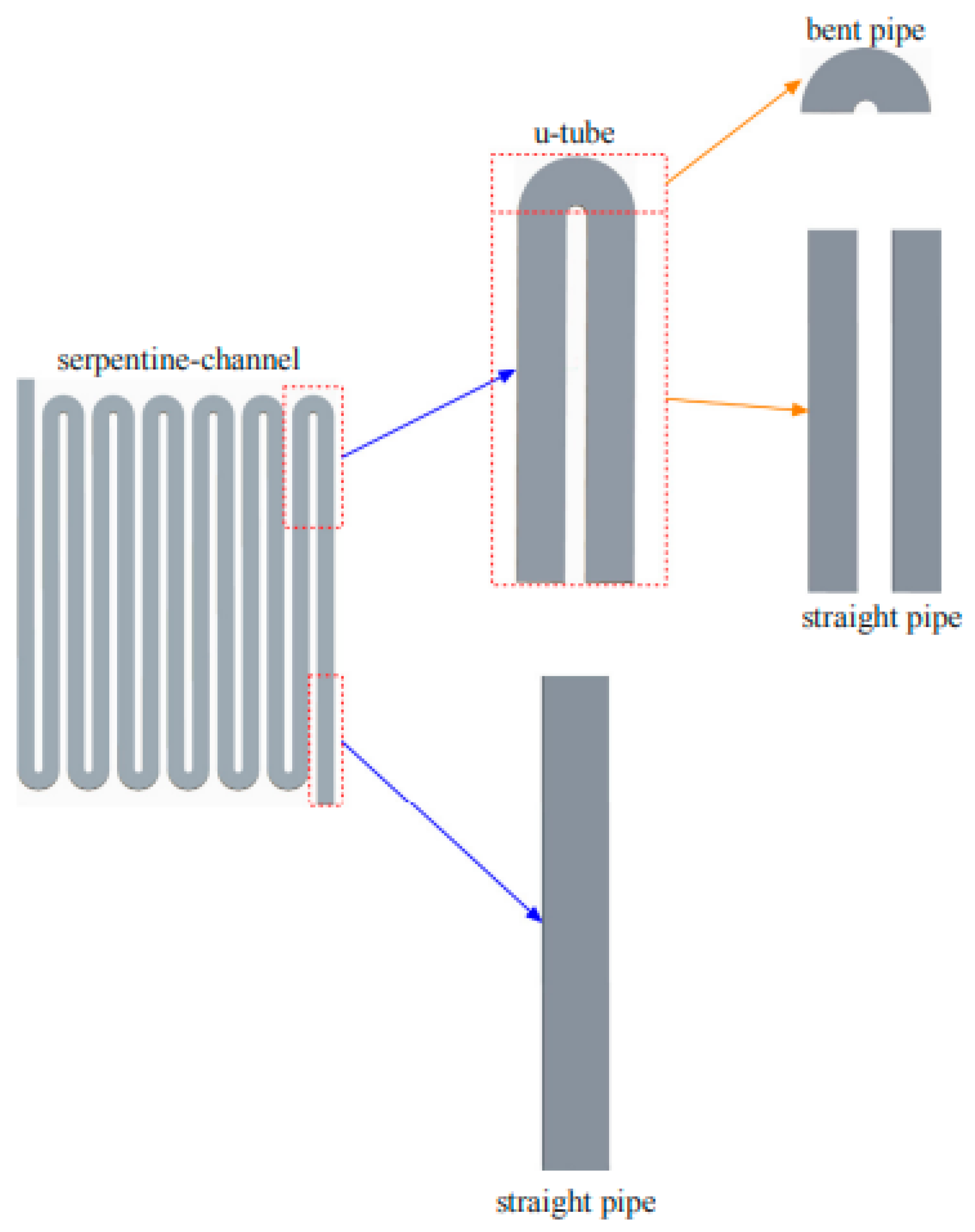
Figure 7.
(a) Liquid cooling system of a battery module; (b) coolant flow path; (c) flow distributor structure; and (d) structure of the liquid cooling plates [51].
Figure 7.
(a) Liquid cooling system of a battery module; (b) coolant flow path; (c) flow distributor structure; and (d) structure of the liquid cooling plates [51].
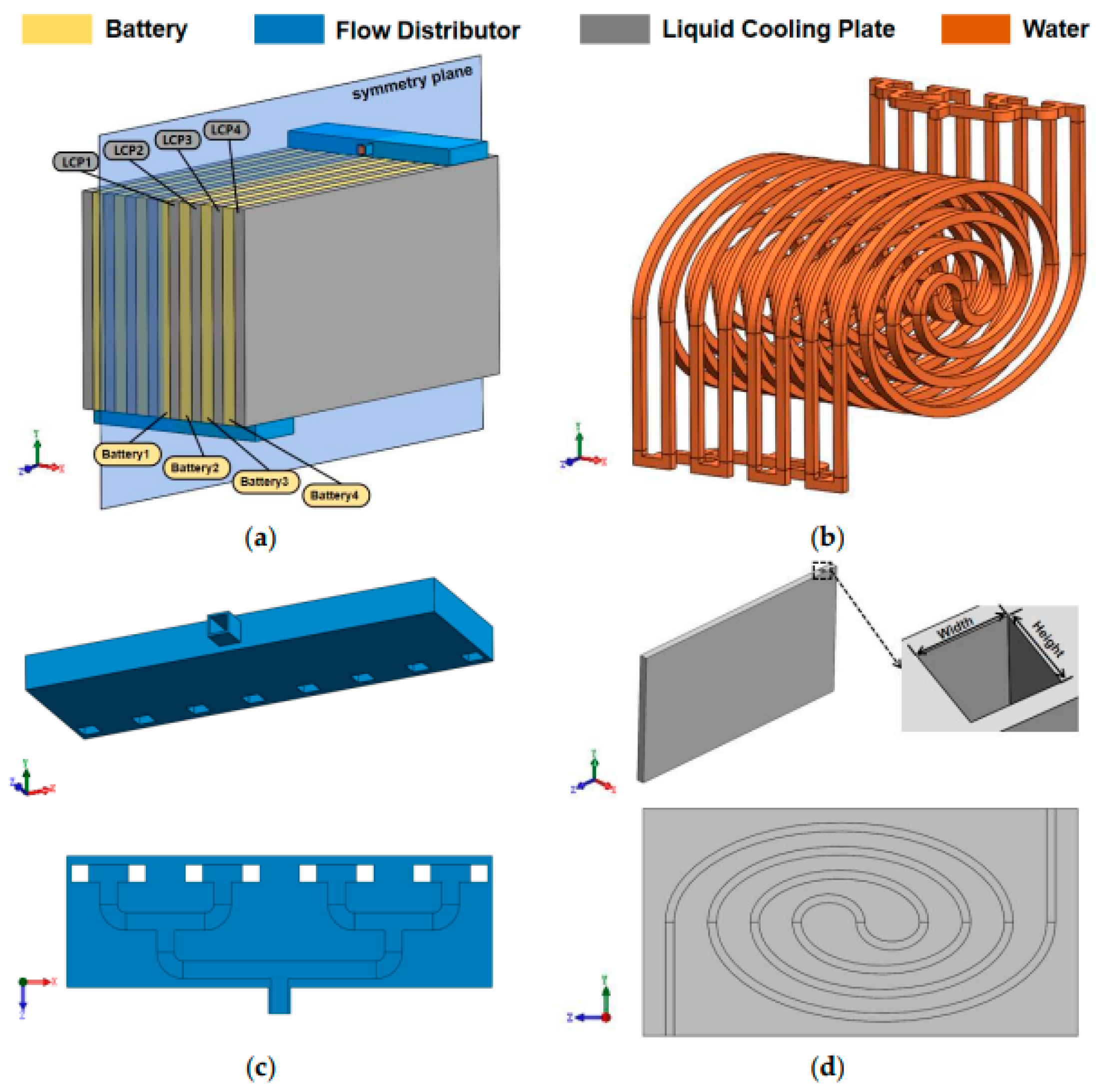
Figure 8.
Li-ion pouch cell with flat tubes [52].
Figure 8.
Li-ion pouch cell with flat tubes [52].
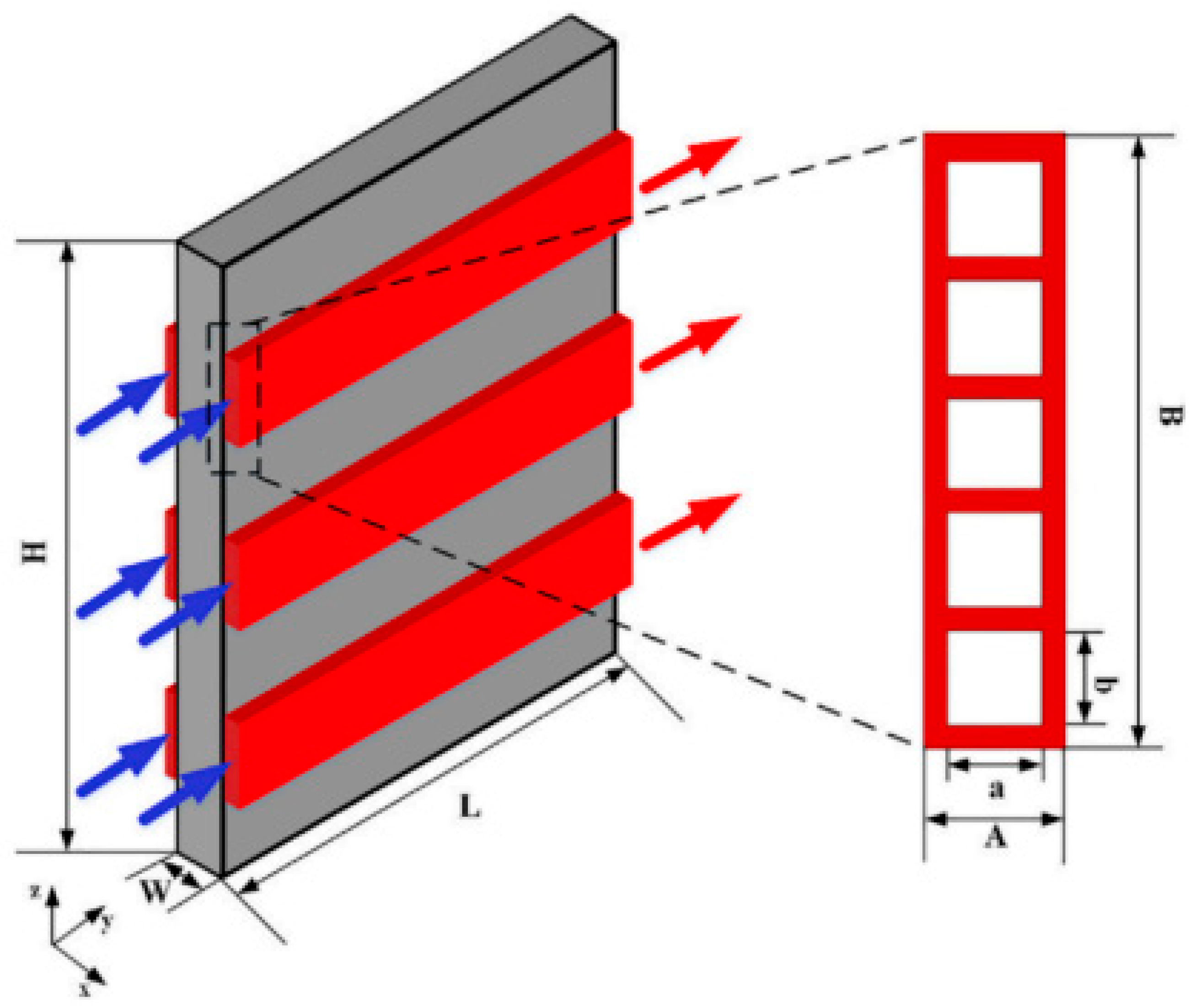
Figure 9.
Si cold plate linked with tubes of copper in a battery module [53].
Figure 9.
Si cold plate linked with tubes of copper in a battery module [53].
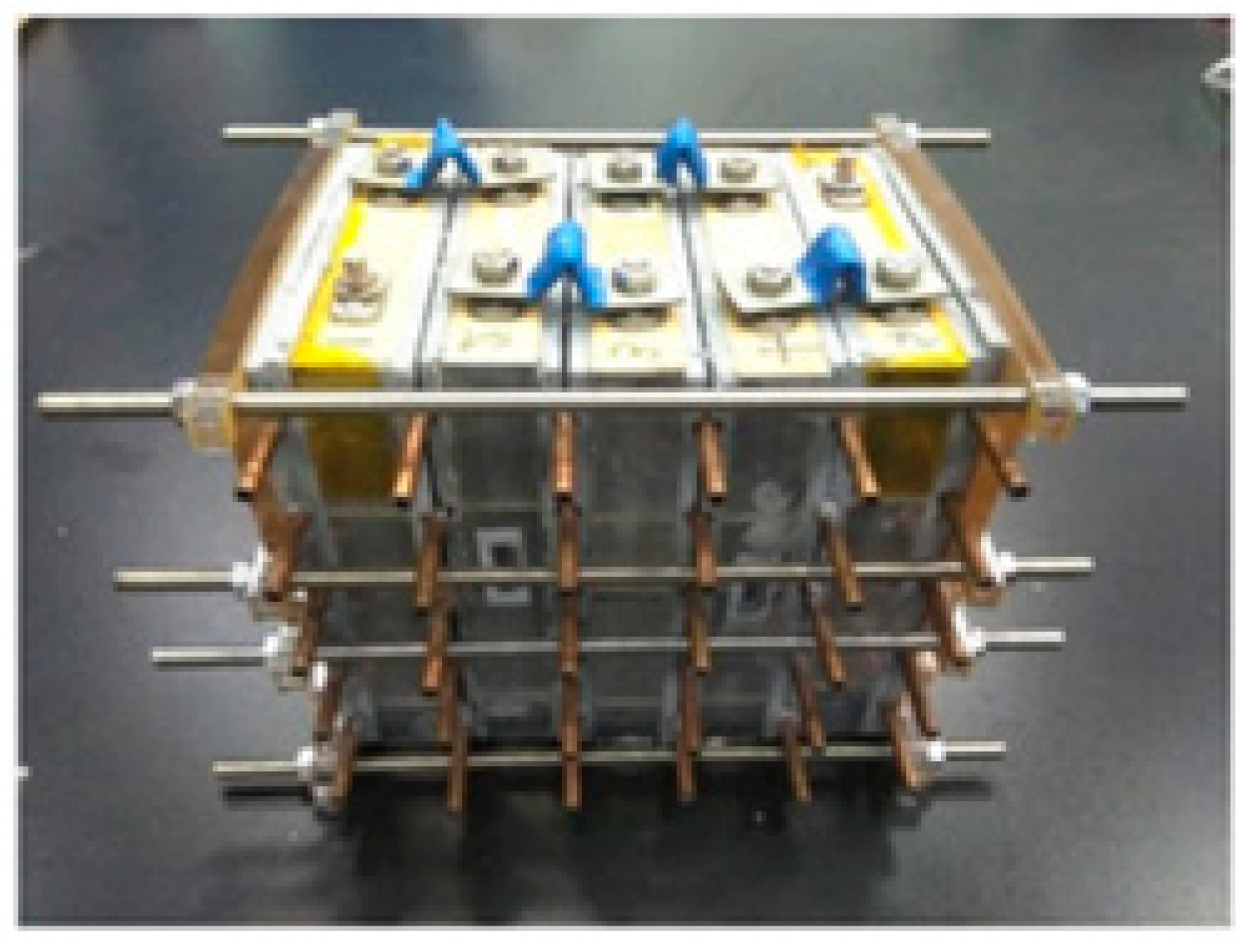
Figure 10.
Water-cooled battery module employing tubes of silicon (a) front side, (b) opposite side [54].
Figure 10.
Water-cooled battery module employing tubes of silicon (a) front side, (b) opposite side [54].
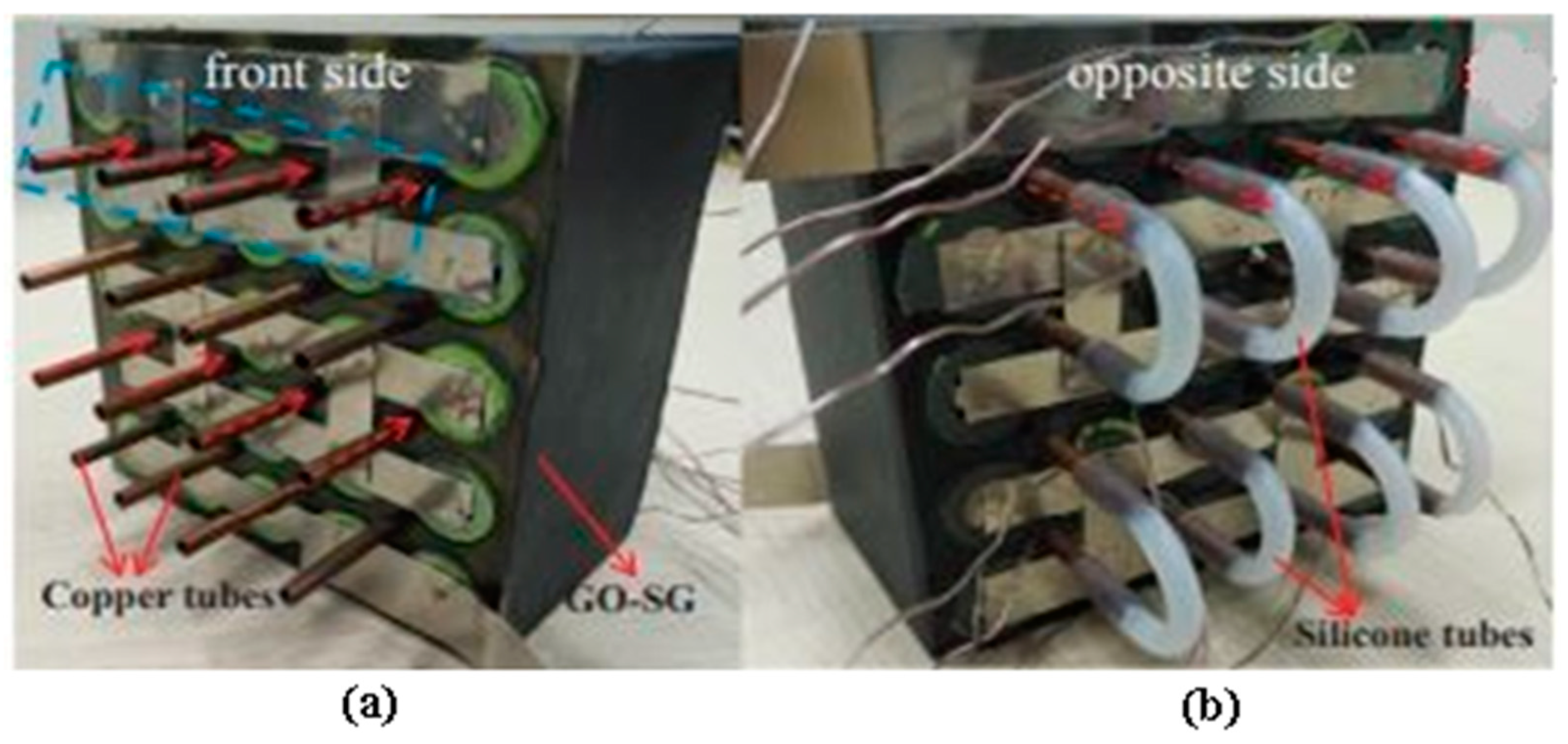
Figure 11.
Li-ion cells consisting of half-helical duct (the number of helical ducts in model varied from one to five) [55].
Figure 11.
Li-ion cells consisting of half-helical duct (the number of helical ducts in model varied from one to five) [55].

Figure 12.
Water-cooled BTMS [56].
Figure 12.
Water-cooled BTMS [56].

Figure 13.
Various configurations of mini-channel cooling system: (a) one strip and four minichannels; (b) one strip and eight minichannels; (c) two strips and four minichannels; (d) four strips and four minichannels; (e) details of the minichannel geometry [57].
Figure 13.
Various configurations of mini-channel cooling system: (a) one strip and four minichannels; (b) one strip and eight minichannels; (c) two strips and four minichannels; (d) four strips and four minichannels; (e) details of the minichannel geometry [57].
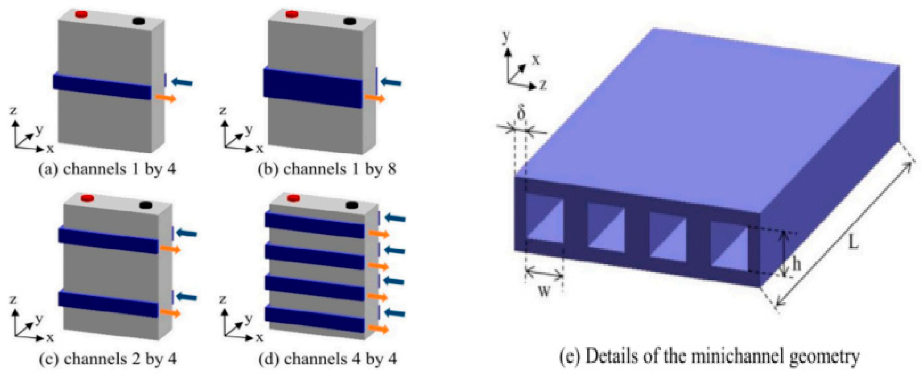
Figure 14.
Liquid cooling [58].
Figure 14.
Liquid cooling [58].
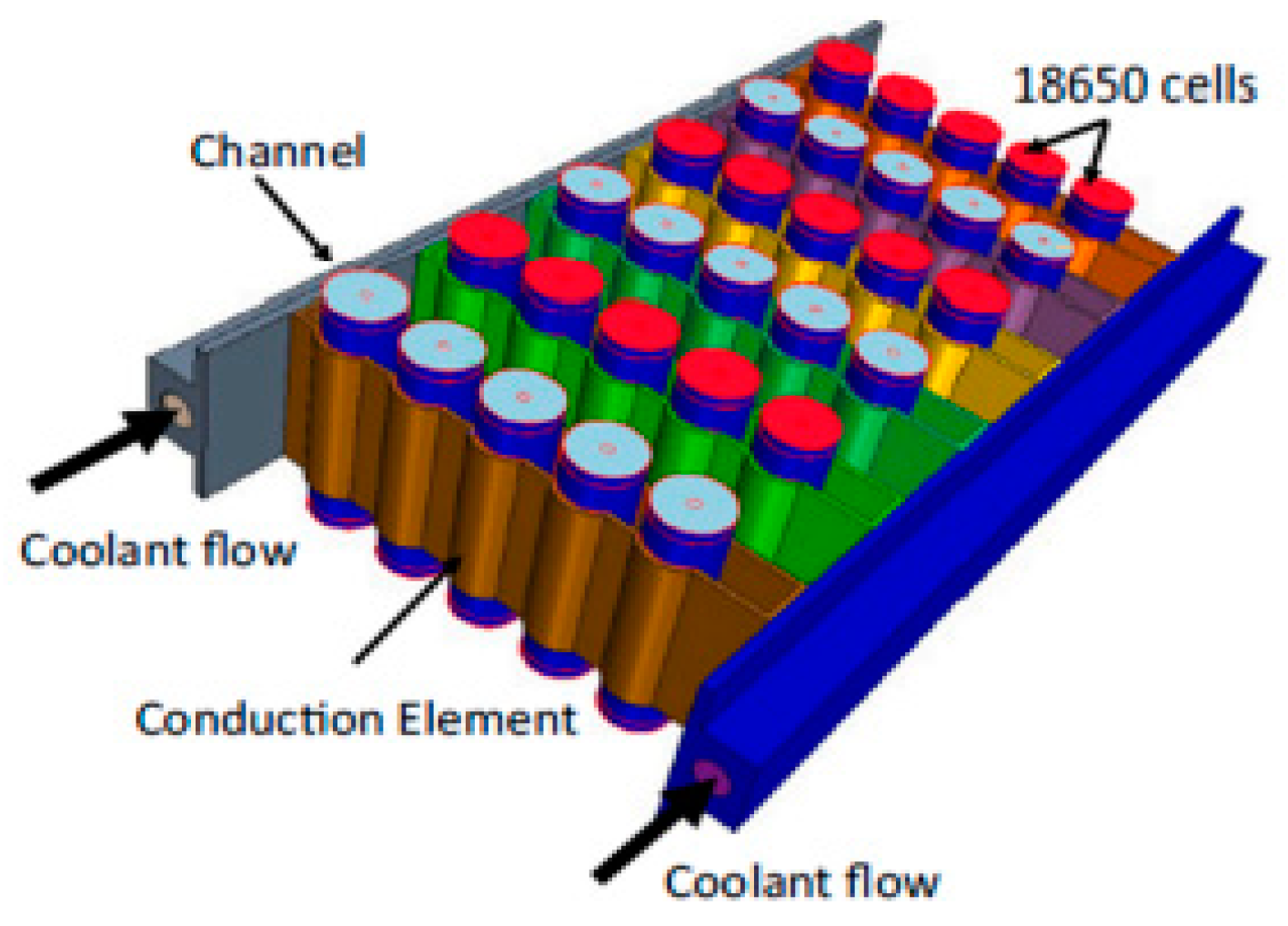
Figure 15.
BLC TMS based on MCFT.
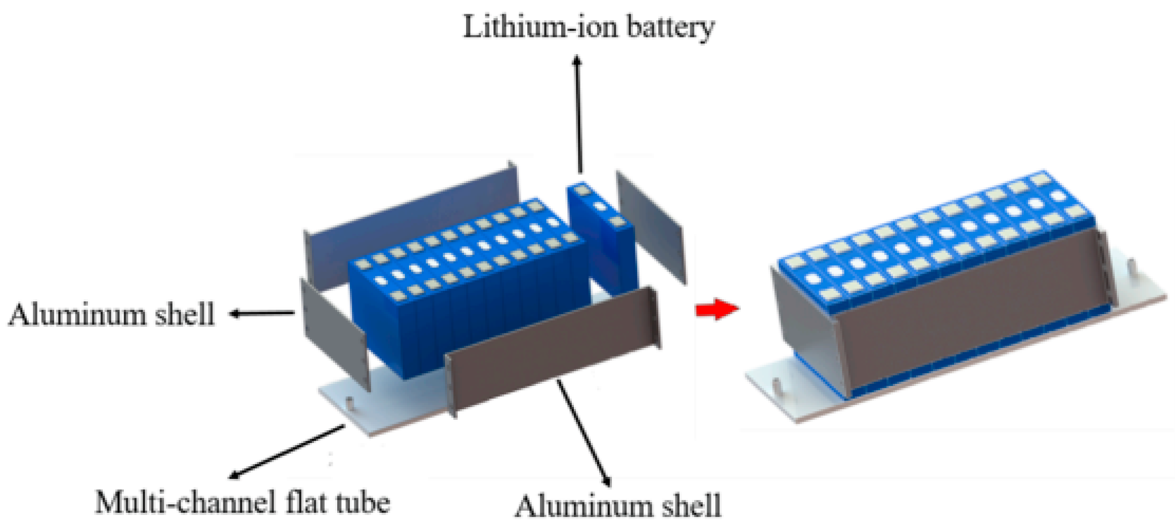
Figure 16.
Different thermal management systems [61].
Figure 16.
Different thermal management systems [61].

Figure 17.
Li-ion battery layout with flow arrangements [63].
Figure 17.
Li-ion battery layout with flow arrangements [63].
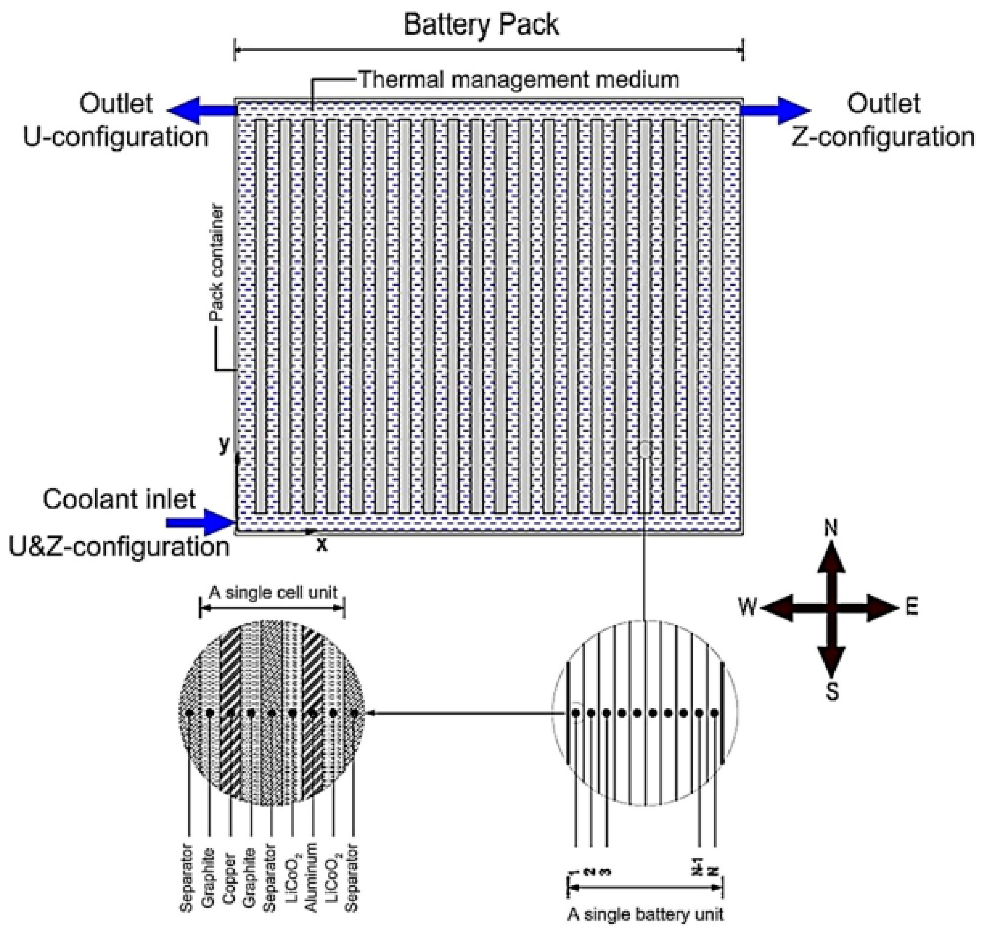
Figure 18.
(a) Liquid filled provision (LfBS) BTMS (b) Liquid circulated arrangement (LcBS) BTMS [69].
Figure 18.
(a) Liquid filled provision (LfBS) BTMS (b) Liquid circulated arrangement (LcBS) BTMS [69].
Disclaimer/Publisher’s Note: The statements, opinions and data contained in all publications are solely those of the individual author(s) and contributor(s) and not of MDPI and/or the editor(s). MDPI and/or the editor(s) disclaim responsibility for any injury to people or property resulting from any ideas, methods, instructions or products referred to in the content. |
© 2023 by the authors. Licensee MDPI, Basel, Switzerland. This article is an open access article distributed under the terms and conditions of the Creative Commons Attribution (CC BY) license (https://creativecommons.org/licenses/by/4.0/).
Share and Cite
MDPI and ACS Style
Anisha; Kumar, A. Identification and Mitigation of Shortcomings in Direct and Indirect Liquid Cooling-Based Battery Thermal Management System. Energies 2023, 16, 3857. https://doi.org/10.3390/en16093857
AMA Style
Anisha, Kumar A. Identification and Mitigation of Shortcomings in Direct and Indirect Liquid Cooling-Based Battery Thermal Management System. Energies. 2023; 16(9):3857. https://doi.org/10.3390/en16093857
Chicago/Turabian StyleAnisha, and Anil Kumar. 2023. "Identification and Mitigation of Shortcomings in Direct and Indirect Liquid Cooling-Based Battery Thermal Management System" Energies 16, no. 9: 3857. https://doi.org/10.3390/en16093857
Note that from the first issue of 2016, this journal uses article numbers instead of page numbers. See further details here.