
Hydrogen-Based Energy Systems: Current Technology Development Status, Opportunities and Challenges


1
Center for Mechanical Technology and Automation, Mechanical Engineering Department, University of Aveiro, 3810-193 Aveiro, Portugal
2
Mechanical Engineering and Resource Sustainability Center (MEtRICs), Mechanical Engineering Department, University of Minho, Campus de Azurém, 4800-058 Guimarães, Portugal
*
Author to whom correspondence should be addressed.
Energies 2024, 17(1), 180; https://doi.org/10.3390/en17010180
Submission received: 12 July 2023
/
Revised: 20 November 2023
/
Accepted: 15 December 2023
/
Published: 28 December 2023
(This article belongs to the Collection Hydrogen Energy Reviews)
Abstract
:The use of hydrogen as an energy carrier within the scope of the decarbonisation of the world’s energy production and utilisation is seen by many as an integral part of this endeavour. However, the discussion around hydrogen technologies often lacks some perspective on the currently available technologies, their Technology Readiness Level (TRL), scope of application, and important performance parameters, such as energy density or conversion efficiency. This makes it difficult for the policy makers and investors to evaluate the technologies that are most promising. The present study aims to provide help in this respect by assessing the available technologies in which hydrogen is used as an energy carrier, including its main challenges, needs and opportunities in a scenario in which fossil fuels still dominate global energy sources but in which renewables are expected to assume a progressively vital role in the future. The production of green hydrogen using water electrolysis technologies is described in detail. Various methods of hydrogen storage are referred, including underground storage, physical storage, and material-based storage. Hydrogen transportation technologies are examined, taking into account different storage methods, volume requirements, and transportation distances. Lastly, an assessment of well-known technologies for harnessing energy from hydrogen is undertaken, including gas turbines, reciprocating internal combustion engines, and fuel cells. It seems that the many of the technologies assessed have already achieved a satisfactory degree of development, such as several solutions for high-pressure hydrogen storage, while others still require some maturation, such as the still limited life and/or excessive cost of the various fuel cell technologies, or the suitable operation of gas turbines and reciprocating internal combustion engines operating with hydrogen. Costs below 200 USD/kWproduced, lives above 50 kh, and conversion efficiencies approaching 80% are being aimed at green hydrogen production or electricity production from hydrogen fuel cells. Nonetheless, notable advances have been achieved in these technologies in recent years. For instance, electrolysis with solid oxide cells may now sometimes reach up to 85% efficiency although with a life still in the range of 20 kh. Conversely, proton exchange membrane fuel cells (PEMFCs) working as electrolysers are able to sometimes achieve a life in the range of 80 kh with efficiencies up to 68%. Regarding electricity production from hydrogen, the maximum efficiencies are slightly lower (72% and 55%, respectively). The combination of the energy losses due to hydrogen production, compression, storage and electricity production yields overall efficiencies that could be as low as 25%, although smart applications, such as those that can use available process or waste heat, could substantially improve the overall energy efficiency figures. Despite the challenges, the foreseeable future seems to hold significant potential for hydrogen as a clean energy carrier, as the demand for hydrogen continues to grow, particularly in transportation, building heating, and power generation, new business prospects emerge. However, this should be done with careful regard to the fact that many of these technologies still need to increase their technological readiness level before they become viable options. For this, an emphasis needs to be put on research, innovation, and collaboration among industry, academia, and policymakers to unlock the full potential of hydrogen as an energy vector in the sustainable economy.
1. Introduction
1.1. Motivation
Since 1992, when the United Nations first recognised climate change as a serious problem, negotiations with a number of countries have yielded significant results [1]. Among these was the Kyoto Protocol, signed in 1997, requiring countries to limit and reduce their greenhouse gas (GHG) emissions [2]. The Paris Agreement, signed in 2015, established the main goals for combating climate change [3]. Its goal is to keep global warming below 2 °C, preferably 1.5 °C, compared to pre-industrial levels. Countries must reach their peak GHG emissions as soon as possible in order to meet this goal. The Paris goals were reaffirmed in 2021 with the Glasgow Climate Pact, emphasising the need to reduce the use of coal and fossil fuels, aiming to achieve carbon neutrality by 2050 [4].
With the growth in the global population and economic development and prosperity of the developing countries, it is expected that the world’s energy needs will grow substantially [5]. In this way, and taking into account the aforementioned objectives, a fundamental challenge with the target of balancing energy demand and supply emerges, requiring innovative methods for producing energy. Therefore, it is crucial to establish a clear path for the utilisation of energy sources and systems to effectively cater to the needs of societies, economies, and the environment [6]. However, the world’s primary energy sources continue to rely on fossil fuels, such as oil, coal, and natural gas. Renewable energy sources (RESs), on the other hand, appear to be the most promising way of replacing traditional energy sources due to their lower GHG emissions, which are in line with the global goal of reducing the carbon footprint [7]. According to Figure 1, in 2021, approximately 84% of the energy consumption came from fossil fuels, 4% from nuclear energy, and 12% from renewable energy sources. RESs include approximately 6.9% hydroelectric power, 3.0% wind power, 1.7% solar power, and the remainder consist of biomass and geothermal energy. However, the most significant barrier to large-scale renewable energy implementation, primarily solar and wind, is their unpredictability and eventual intermittent availability [5].
An energy carrier is a secondary energy source. This is because it is a kind of substance or device that stores energy that has already been converted from its original form (the primary energy) to a different energy type which is more suitable to be stored, transferred and converted to useful work. Hydrogen is considered an energy vector because it is not a primary source of energy but rather a means of storing and transporting energy. Hydrogen is not normally found naturally on Earth in pure form. Instead, it is usually combined with other elements. To obtain pure hydrogen, production processes such as the electrolysis of water or the reforming of natural gas must be carried out. Non-carbon fuels like hydrogen are viewed as a long-term solution to some of the issues associated with climate change and energy sustainability [6]. Green hydrogen, produced through RES, is a versatile and nearly zero-emission fuel with the potential to decarbonise highly emissive sectors, including transportation, industry, electricity generation, and heat production [9]. As a result, demand for hydrogen is expected to rise significantly from 94 Mt, in 2021, to around 180 Mt, in 2030, making it a critical component of future global energy policies [10].
There is still significant room for improvement in the global efficiency of hydrogen-based energy conversion. In order to estimate the efficiency of the hydrogen supply chain based on the current efficiency of the processes, one can consider the following scenario: assume that 1 kWh of renewable energy is supplied to a PEM electrolyser with an efficiency of 60%, followed by the storage and transportation of compressed hydrogen at 70 bar, which incurs losses of approximately 20%. To recover the energy, a PEMFC with an efficiency of around 50% is utilised. After these transformation processes, it is possible to recover approximately 0.24 kWh of energy, which represents an energy loss of about 75%. This value of losses in the described hydrogen supply chain is indeed quite high. The observed losses emphasise the imperative for enhancing the efficiencies of each individual process involved.
Despite the still high losses in the global energy conversion processes involving hydrogen, over time, an increasing number of nations have embraced policies and strategies involving this energy vector [11]. These differ at various levels, including research and development (R&D) programmes, vision documents, road maps, and strategies. They may differ in focus (only green hydrogen, based on fossil fuels, or a combination) and scale (with or without outlined goals and on the amount of hydrogen and electrolysers) [11]. Most countries are currently in the strategic phase and require concrete policies. The European Union has set ambitious goals for green hydrogen, aiming to reach a capacity of 40 GW of electrolysers by 2030 [12], up from 500 MW in 2021 [13].
1.2. Objectives and Methodology
The increasing fascination and enthusiasm with hydrogen that are often seen in policy markers need to be grounded in sound knowledge of the challenges and opportunities presented by this energy vector and its associated technologies. This calls for a comprehensive assessment of hydrogen production, specifically focusing on green hydrogen, storage and distribution, as well as energy conversion technologies. Despite numerous studies conducted on this subject, only a limited number of them seem to address the intersection of multiple disciplines simultaneously. Many of these studies tend to concentrate solely on the technical, social, or political aspects of hydrogen technologies. Therefore, this article aims to perform a multidisciplinary study to examine the current state of hydrogen technologies and foster broad discussions. The objective is to shed light on the recent advancements, identify the challenges encountered, and outline potential areas for future development regarding hydrogen technologies, policies, regulations, and social considerations. Based on a comprehensive literature review, it might be a help for scientists, researchers, engineers, policy makers, investors, financiers, financing programmes’ designers, and companies to make better and more supported decisions while designing effective operations and business models for hydrogen-based energy systems, taking into account their potentials, challenges, needs, and opportunities.
The Web of Science database was used to develop the state-of-the-art review, which included several keywords, among which are:
- Title included—“Hydrogen”;
- Document type—“Review Article”;
- Web of science category—“Energy Fuels”;
- Publication year—“2022 or 2021 or 2020”.
This search revealed 539 articles. Those that did not deal with the topic of this article were excluded, leaving around 150 papers to be reviewed.
1.3. Technology Readiness Level
The Technology Readiness Level (TRL) scale is used to assess the maturity of new technologies, and in this particular case to analyse and communicate the readiness of different hydrogen-related technologies [14]. The TRL scale starts at level 1, where the basic principles of the technology are defined. As the technology progresses, it reaches level 2 when the concept and application area develop and level 3 when an experiment proves its concept. The next phase involves validating the concept, starting with a laboratory prototype (level 4) and moving on to tests in the intended conditions (level 6). The technology then enters the demonstration phase, being tested in real environments (level 7) and achieving a first-of-its-kind commercial demonstration (level 8) on its way to full commercial operation (level 9).
However, reaching level 9 does not guarantee that the technology is ready to meet the energy policy objectives. The International Energy Agency (IEA) has extended the TRL scale to include two additional levels [15]. Level 10 represents a stage where the technology is commercially available and competitive but requires further innovation efforts for integration into energy systems and value chains at scale. Level 11 indicates that the technology has achieved predictable growth.
2. Hydrogen
2.1. Introduction
Hydrogen is the most abundant element in the Universe, and it is primarily found on Earth in molecules such as water and organic compounds [16]. It is the first and simplest element in the periodic table, having the smallest atomic mass of 1.008 g/mol and being composed of only one proton and one electron [17,18]. Atomic hydrogen does not exist under normal conditions [18]. In turn, hydrogen is found as a two-atom combination, forming the hydrogen molecule (H2).
This section covers the essentials of hydrogen’s history. Following that, the main physical and chemical properties of hydrogen are described in order to demonstrate what makes it a potential energy vector. Finally, the safety required for its handling is discussed, as well as the main associated ISO standards.
2.2. The History of Hydrogen
Scientists obtained and used hydrogen for years before it was recognised as an element. Much has changed between the 16th and 21st centuries, with new hydrogen-related technologies being developed as represented in Figure 2.
After figures such as Paracelsus [19] and Boyle [20] observed the formation of an unidentified gas in chemical reactions, it was only in the late eighteenth century that Henry Cavendish reported hydrogen as a unique substance [16] and Antoine Lavoisier coined the term “hydrogen” from the Greek words “hydro” (water) and “genes” (producing) [18]. Later, William Nicholson and Anthony Carlisle used Volta’s pile with copper electrodes for experiments on water electrolysis [21]. Forty-two years later, William Robert Grove developed the first hydrogen fuel cell [16]. In 1875, Jules Verne published the novel The Mysterious Island, where he wrote how “water will one day be employed as fuel, that hydrogen and oxygen which constitute it, used alone or simultaneously, will furnish an inexhaustible source of heat and light, of an intensity of which coal is not capable” [19]. In 1898, James Dewar succeeded in liquefying hydrogen [16]. At the end of the 19th century, Ferdinand von Zeppelin made the first flight in the first hydrogen balloon [19].
J. B. S. Haldane proposed a network of hydrogen-producing windmills at the turn of the twentieth century, in 1923, predicting that coal supplies would eventually run out [19]. This was the first “hydrogen-based” business proposal involving hydrogen. The hydrogen-powered airship LZ 127 Graf Zeppelin circumnavigated the globe for the first time in about 21 days in 1928 [19]. The Hindenburg airship explosion in 1937 was an event that would shape public perception of hydrogen safety [22]. In 1961, the first liquid hydrogen-powered rocket was launched [16]. Five years later, General Motors (Detroit, MI, USA) introduced the Electrovan, the first automobile to use fuel cells [19]. The term “hydrogen economy” was coined by John Bockris and Lawrence W. Jones in 1970 [19].
The 21st century is being marked by the implementation of hydrogen technologies which persist up to the present day. In 2002, Jeremy Rifkin published The Hydrogen Economy, in which he theorised about how “weaning the world off oil and turning it toward hydrogen” was critical to global security [19]. In 2008, the European Commission established the Fuel Cells and Hydrogen Joint Undertaking, later renamed the Clean Hydrogen Joint Undertaking, with the aim of speeding up the market introduction of fuel cells and other hydrogen-related technologies [23]. Toyota (Toyota, Aichi, Japan unveiled the Mirai, its first commercial hydrogen passenger car with fuel cells, in 2014 [24]. The Hydrogen Valleys Platform launched a project two years later to promote collaboration on large-scale hydrogen projects [25]. Since there has been significant European investment in hydrogen-related technologies beginning in 2020, these policy makers expect that the hydrogen economy will be implemented on a much larger scale in sectors with intense GHG emissions [19].
2.3. Hydrogen Properties
Under normal conditions, hydrogen is a colourless and tasteless combustible gas [26]. Because it is renewable, non-toxic, and carbon-free, it is expected to significantly improve air quality [27]. In the remainder of the article, the term “hydrogen” will mainly be used as a synonym for the H2 molecule.
Physical and chemical properties both have an impact on how a substance is used and handled. This is especially true when it comes to the safe handling and storage of energy carriers such as hydrogen.
Under normal conditions, hydrogen exists as a gas. In fact, its normal boiling point at normal pressure (1.013 bar) is very close to absolute zero, at −252.8 °C (20.4 K) [16]. Of course, temperature and pressure influence the hydrogen aggregation state. By increasing the pressure, gases can be liquefied. Regardless of the pressure, there is a critical temperature above which they can no longer be liquefied. The critical temperature for hydrogen is −240 °C (33.2 K) [28]. As a result, in order to liquefy hydrogen, its temperature must be lower than this point. The pressure known as hydrogen’s critical pressure is 13 bar [28]. Thus, the critical temperature and pressure of a substance, which in the case of hydrogen are −240 °C and 13 bar, define its critical point. At this point, the hydrogen density is 31 g/L [28].
At normal pressure, the melting point of H2 (the temperature at which it changes from solid to liquid) is −259.2 °C (13.9 K), which is slightly lower than the boiling point [16]. A substance’s triple point is the point on the phase diagram at which all three aggregation states are in thermodynamic equilibrium. This point for hydrogen is −259.3 °C and 0.07 bar [16]. The triple point is also the vapour–pressure curve’s minimum point. The pressure–temperature combination at which the gaseous and liquid states are in equilibrium is indicated by this curve (purple). Hydrogen is a liquid to the left of that curve and a gas to the right of that curve. Above and to the right of the critical point, hydrogen transforms into a supercritical fluid, which is neither gaseous nor liquid. In comparison to other substances, hydrogen’s vapour–pressure curve is rather steep and short [18]. As a result, hydrogen liquefaction occurs primarily through cooling and less through compression.
Figure 3 represents the hydrogen phase diagram, which shows the critical point (green), triple point (orange), melting curve (pink), vapour–pressure curve (purple), and solid, liquid, and gaseous states of aggregation.
The negative Joule–Thomson coefficient of hydrogen is a unique property [28]. Under normal conditions, when air adiabatically expands, it cools down, which is used in gas liquefaction. However, hydrogen behaves differently; when it is adiabatically expanded, it heats up. Hydrogen exhibits “normal” Joule–Thomson effect behaviour only below its inversion temperature of −73 °C (200 K) [28].
Density is defined as the mass-to-volume ratio. At 0 °C, the density of hydrogen in its gaseous state is 0.089 g/L [30]. With a density of 1.29 g/L, air is approximately 14 times heavier than hydrogen gas, giving hydrogen high buoyancy in the atmosphere and making it highly volatile in open air [28]. Hydrogen has a density of 70.8 g/L in liquid form at the boiling point [31]. It has a density of 76.3 g/L at the melting point of −259.2 °C and 1.013 bar [18]. Thus, liquefaction increases the density of hydrogen by a factor of 800 (0.089 g/L to 70.8 g/L) while considerably decreasing its storage volume [18]. To compare, the corresponding factors for liquefied petroleum gas (LPG) and liquefied natural gas (LNG) are approximately 250 and 600, respectively [18].
The energy content of an energy carrier greatly influences how it is stored. The calorific value of an energy source, or more accurately, its lower and higher heating values, determines its energy content. The amount of net heat released in a (theoretically) complete combustion is defined as the lower heating value (LHV). The higher heating value (HHV) additionally considers the energy released during the condensation of the water vapour produced during combustion [18]. The calorific value usually has a mass basis, expressed in MJ/kg. It is also possible to describe it on a volume basis, MJ/L, using density (kg/L). The gravimetric and volumetric energy densities of hydrogen in various states of aggregation, as well as those of other common fuels, are depicted in Figure 4 [32]. As can be seen, in terms of gravimetric energy density, hydrogen has by far the highest LHV of 120.1 MJ/kg [33]. The HHV (not shown in the figure) can be as high as 141.8 MJ/kg [16]. As a result, the LHV is nearly three times greater than that of liquid hydrocarbons. The volumetric energy density of hydrogen, on the other hand, is relatively low. Its value is only of 0.01 MJ/L under normal conditions [18]. As a result, in order for hydrogen to be used in practice, its density must be strongly increased so that it can be stored in a reasonably small volume.
Another important property of hydrogen is its extreme diffusivity. Because hydrogen is the lightest of gases, it can diffuse into other media at a rate of 0.61 , causing embrittlement in porous materials and even in metals [33].
The flammability of hydrogen is an important chemical property. When hydrogen is burned in the open air, the flame is barely visible in daylight, as it has low heat radiation and a high ultraviolet radiation component [18]. Hydrogen has a broad ignition spectrum when compared to other fuels. This range is constrained by the lower and upper flammability limits, which for H2 are 4% and 76% concentrations in air, respectively [30]. Only methane has an upper limit close to 15%, which still falls short of that of hydrogen as shown in Figure 5.
Hydrogen is an interesting fuel due to its combustion properties and absence of carbon in its composition. Its wide ignition range would allow for fairly lean air/hydrogen mixtures in internal combustion engines. While gasoline engines use a stoichiometric combustion air ratio and diesel engines use , hydrogen combustion engines could use values as high as 10 [18,30]. Because lean combustions are more efficient, they use less fuel for the same amount of energy used.
Pure hydrogen has a higher self-ignition temperature than conventional fuels, at 585 °C [33]. The minimum energy required for hydrogen ignition, on the other hand, is of only 0.02 mJ, which is lower than for other common fuels [30]. As a result, hydrogen is classified as a highly flammable gas. A single electrostatic discharge of around 10 mJ, on the other hand, is sufficient to ignite other fuels [18]. Hydrogen has a maximum flame speed of 346 cm/s, considerably higher than those of other common fuels [18].
The hydrogen molecule is a relatively inert substance. However, by heating a 2:1 hydrogen/oxygen mixture to 600 °C, a chain reaction can begin, resulting in a spread of temperature rise throughout the mixture [18]. The water vapour produced by the reaction’s heat expands to a greater volume than the original mixture. The rapid spread of water vapour causes an oxyhydrogen reaction, also known as the Knallgas reaction [18].
Hydrogen possesses various physical and chemical properties that render it an intriguing fuel option. However, it requires careful handling and adherence to safety regulations, as not all of its properties are equally favourable.
2.4. Safety and Standards
It should be noted that when it comes to safety, hydrogen does not have a positive connotation. The fear of this molecule can be traced back to the Hindenburg disaster in 1937 (Section 2.2), in which the destruction of the airship caused fear of hydrogen among the general public [35]. This incident serves as a reminder of hydrogen’s explosive and highly flammable nature. However, because hydrogen has several advantages, it can be used in a way that reduces the risk to human life and property to an acceptable level with proper training, rules, codes, and standards, as well as appropriate systems [26].
When discussing safety, one is discussing something that cannot be easily quantified. As a result, three concepts must be distinguished: hazard, risk, and safety. A hazard is “a chemical or physical condition that may harm people, property, and the environment”; a risk is “a combination of likelihood and the consequences that occur at a certain time”; and safety is “the freedom from a risk that is not tolerable” [36]. Thus, risk includes the possibility of hazard being converted into damage [37]. Based on this, society can define an acceptable level of risk and classify it. As a result, the discussion of safety includes hazard perception, risk analysis, and risk acceptance.
The hazards associated with hydrogen can be classified into three categories: (1) physiological, where there is frostbite and asphyxiation; (2) physical, where embrittlement and component failure are integrated; and (3) chemical, with fire or explosion [28,37]. The difficulty in hydrogen safety stems from its properties, which include a wide flammability range, low ignition and detonation energies, a non-luminous flame, and a highly buoyant and diffusive nature [38].
Hydrogen has a high auto-ignition temperature, suggesting that it is safe. However, when compared to other fuels, the energy required to initiate ignition is much lower. As a result, any potential ignition and/or heat sources, such as static electricity, hot objects, flames, and electrical equipment (sparks), must be eliminated, and hydrogen-handling devices must be grounded [28]. When hydrogen burns, it shines with an almost invisible pale blue colour, making it difficult to detect. As a result, it must be handled with extreme caution during ignition and combustion. Its flame is typically in the form of a torch or jet that originates at the H2 discharge point [38].
Failures due to brittle fracture and reduced ductility can be observed when metallic materials are used in the production or processing of H2, an effect known as embrittlement [39]. H2 migrates into the structure and begins to integrate due to its smaller size and high kinetic energy. As a result of the defects caused by hydrogen, the structure may begin to fail.
The velocity of steam generation from liquid hydrogen is much faster than that of other fuels, resulting in a very short period of hydrogen fire [28]. However, because combustion produces water, the inhalation of H2 combustion smoke is safe, with no risk of smoke asphyxiation. Hydrogen by itself is not explosive. However, an explosion can occur in the presence of an oxidising gas, such as oxygen. The combination of hydrogen and air can cause combustion, which releases energy and shock waves as a result of the explosion [38]. Furthermore, a mixture of H2 and air is more likely to detonate than a mixture of other fuels and air. However, due to the rapid dispersion of H2, this detonation tends to occur in confined spaces only [28].
Because of its extremely low temperature, liquid hydrogen (LH2) requires more attention and care than gaseous hydrogen. Thermal burns, including frostbite and hypothermia, result from direct contact with LH2 and its boil-off gas [28]. Furthermore, inhaling cold hydrogen vapour can result in respiratory illness and asphyxiation [28]. An explosion can occur if LH2 is released or leaks. When liquid hydrogen vaporises, it quickly turns into gaseous hydrogen, which explodes when reacting with air [28].
Several standards have been developed to support the use of hydrogen in both gaseous and liquid forms. The International Standards Organisation (ISO, Geneva, Switzerland) has issued several hydrogen-related guidelines. In 1990, the Technical Committee (TC) 197 was formed to develop standards for systems and devices used in the production, storage, transport, and measurement of hydrogen [40].
- ISO/TR 15916:2015 specifies guidelines for the use and storage of gaseous or liquid H2. The standard identifies the fundamental safety concerns, hazards, and risks, as well as H2 properties that are relevant to safety [41].
- The minimum quality characteristics of hydrogen fuel as dispensed for use in mobile and stationary applications are specified in ISO 14687:2019 [42].
- ISO 22734:2019 specifies the design, safety, and performance requirements for electrochemical hydrogen generators that electrolyse water to produce H2 [43].
- ISO 23273:2013 specifies the essential requirements for fuel cell vehicles (FCV) in terms of protecting people and the environment from hydrogen-related hazards both inside and outside the vehicle [46].
3. Green Hydrogen Production Processes
3.1. Introduction
Hydrogen can be generated using a wide range of energy sources and technologies. It is thus an energy vector because it is a substance that stores energy as a result of the transformation of primary energy. Fossil fuel sources dominate its current production [47]. As seen in Figure 6, by the end of 2021, natural gas (69.5%), coal (29.5%), and oil (0.79%) accounted for more than 99% of global hydrogen production. Only 0.14% is generated by electricity, with the remainder (0.04%) being generated by biomass. As a result, hydrogen can be extracted not only from fossil fuels but also from biomass and even water [48].
In this section, the various processes of hydrogen production via fossil fuel, biomass, and water sources are discussed and characterised in a colour spectrum. Through the definition of green hydrogen, water electrolysis technologies, such as alkaline water electrolysis, anion exchange membrane electrolysis, proton exchange membrane electrolysis, and solid oxide electrolysis, will be specifically described and analysed.
3.2. Hydrogen Production Processes
Because of their low production costs, fossil fuels continue to dominate hydrogen production. There are currently several mature technologies for producing H2 from fossil fuels, the most common of which being hydrocarbon reforming and pyrolysis. In Figure 7, one can understand the different processes for the production of hydrogen from fossil fuels and from renewable energy sources.
3.2.1. Hydrogen Production from Fossil Fuels
Hydrocarbon reforming is the most advanced technique for producing H2. Other reactants, such as water vapour or oxygen, are required for the process in addition to hydrocarbons. However, carbon monoxide (CO) is also produced in addition to hydrogen. Steam methane reforming (SMR) is the reaction of steam with hydrocarbons, usually natural gas (methane), at high temperatures (800–1000 °C) [49]. Because this is a highly endothermal reaction, a significant amount of heat is required for it to take place. An alternative to steam reforming is partial oxidation (POX). It is a process that uses high temperatures to convert heavy fuel oil or coal into a mixture of H2 and CO. One advantage of this process is that it is exothermal, which means that no external heat sources are required [50]. When the two preceding processes, SMR and POX, are combined, the result is known as autothermal reforming (ATR). In this way, POX, in conjunction with O2, provides the energy required for SMR, thereby rendering the process thermally neutral [51]. It requires less energy than other processes due to its high thermal efficiency. The Global Warming Potential (GWP) of SMR and ATR is fairly high, rated at 11–13 and 13.3 kg CO2eq/kg H2. But it could drop to values as low as 1.14 and 0.64 kg CO2eq/kg H2 if carbon capture and storage are implemented [52].
Pyrolysis is a thermal decomposition process that converts various light liquid hydrocarbons into elemental carbon (C) and hydrogen in the absence of oxygen [53]. It is typically processed in two stages: hydrogasification and methane cracking. Because the recovered carbon is in the solid state, the pyrolysis of methane (CH4) does not produce carbon dioxide (CO2). Coal gasification is a thermochemical process that converts coal into synthesis gas, which is a mixture of H2 and CO. At high temperatures and pressures, coal is converted into syngas using steam and oxygen (or air) [54]. The main issue with this hydrogen production method is the high CO2 emissions, at around 16 kg CO2eq/kg H2 [55].
3.2.2. Hydrogen Production from Biomass
The amount of hydrogen obtained through biological processes has increased in recent years as a result of increased attention to sustainable development and waste minimisation. Dark fermentative H2 production and photo-fermentative processes are the primary processes. Anaerobic bacteria are used in dark fermentative processes to produce H2, organic acids, and CO2 on carbohydrate-rich substrates in the absence of light and under low-oxygen conditions [56]. H2 can be produced at any time because no light is required. In photofermentation, on the other hand, photosynthetic bacteria use sunlight as an energy source and assimilate small organic molecules present in the biomass to produce H2 and CO2 [57]. When compared to the yield under sunlight, the hydrogen yield rate is typically lower in the dark fermentative processes.
Some of the most efficient methods for producing H2-rich gases from biomass are thermochemical processes. Pyrolysis, gasification, and hydrothermal liquefaction are the most common ones. When gasification and pyrolysis are used, the thermochemical conversion of dry biomass is similar to that of fossil fuels. Both the aforementioned technologies generate CO and CH4, which can be used to increase H2 production via steam reforming and water–gas shift reactions. Biogas reforming has an average GWP of 3.61 kg CO2eq/kg H2, but depending on the circumstances, it could be negative or exceed 8 kg CO2eq/kg H2 [55]. Hydrogen could be obtained from humic biomass through a combination of hydrothermal liquefaction and steam reforming [48]. Actually, one of the possible technologies to obtain hydrogen from dissolved organics is aqueous phase reforming as reported by several authors [58,59,60,61]. Because it involves all chemical reactions to obtain products with zero oxygen concentration, pyrolysis is regarded as the starting point for all thermochemical conversion technologies. Dry biomass is typically pyrolysed between 300 and 1000 °C [48]. After thermal decomposition, the products include biochar, bio-oil, and gases such as hydrogen, methane, and other hydrocarbon gases. The conversion of dry biomass into a gaseous fuel mixture at high temperatures (800–900 °C) to increase hydrogen production is known as biomass gasification [48]. Biomass is primarily converted into CO and H2 at the end of gasification but also water, CO2, and CH4. This is a process that requires the use of oxidants such as air, oxygen, or steam. To break down the polymeric structure of the biomass, the hydrothermal liquefaction of wet biomass is typically carried out at moderate temperatures (250–370 °C) and high pressures (4–22 MPa) [48]. This method produces a liquid biocrude, a gaseous stream, an aqueous phase, and a solid waste by-product. Following steam reforming, hydrogen-rich syngas is produced. Biomass gasification has an average GWP rating of 1.67 kg CO2eq/kg H2 [55].
3.2.3. Hydrogen Production from Water
Water is a plentiful resource for hydrogen production, and it can be split into hydrogen and oxygen with enough energy while emitting no harmful emissions. In its most basic form, water splitting uses an electric current (electrolysis) passing through two electrodes to split the water into H2 and O2. However, other energy sources, such as thermal energy (thermolysis), photonic energy (photo-electrolysis), and biophotolysis using microorganisms, can also be used to split it.
One of the most basic methods for producing hydrogen from water is electrolysis. It is the conversion of electrical energy into chemical energy in the form of hydrogen and oxygen as a by-product (this process is further detailed in the following section) [62]. It is regarded as a promising technology, but its production costs are high. Thermolysis is a thermochemical water-splitting process that uses high temperatures to decompose water into H2 and O2 [63]. Although it is a simple process, water decomposition requires temperatures above 2500 °C. Because this is a reversible process, one of the primary challenges in its application is the separation of the produced H2 and O2, as recombination of these gaseous products can result in an explosive mixture (as described in Section 2.4). Another issue is the scarcity of materials that can withstand the required high temperatures. Regarding GWP, it is highly dependent on the electricity production, being as low as 1.13 kg CO2eq/kg H2 for the power grid mix of Norway in 2015, which is strongly based on hydropower, around 2 when using a Photovoltaic source, to 35 kg CO2eq/kg H2 for the grid mix of the Netherlands in 2015 [52].
Photoelectrolysis is similar to electrolysis, but it includes the absorption of solar energy from a photoelectric cell. This is a process that requires both solar and electrical energy and converts it into chemical energy as H2 [64]. Biophotolysis is a photonic biochemical process that produces H2 from water. Under anaerobic conditions, microorganisms such as green microalgae or cyanobacteria use photosynthesis to split the water molecule into H2 and O2 [65]. Under these conditions, hydrogen can be produced in an aqueous environment. However, due to the low H2 yield, a large surface area is required to collect enough sunlight. In indirect biophotolysis, carbohydrates are accumulated during the CO2 fixation step, and only in the next step is H2 produced.
3.3. Hydrogen Colour Code
The climate benefit of hydrogen is dependent on how it is produced. As illustrated in Figure 8, hydrogen can be distinguished by colour grading based on its production method and carbon footprint.
3.3.1. Black and Brown Hydrogen
3.3.2. Grey Hydrogen
Grey hydrogen is the most common method of production right now [68]. Hydrogen is produced using fossil fuels, and while it is not as harmful to the environment as black or brown hydrogen, the CO2 produced is still quite significant in terms of its GWP because it is released into the atmosphere [69,70].
3.3.3. Turquoise Hydrogen
Turquoise hydrogen is extracted by the pyrolysis of methane [71]. This is a relatively new process that removes solid carbon rather than emitting CO2 [72]. Solid carbon is an essential raw material that can be used to make tyres, plastics, batteries, etc. The process uses natural gas as a feedstock, and if the energy used is renewable, the carbon footprint will be close to zero [19,73].
3.3.4. Blue Hydrogen
Blue hydrogen is derived from fossil fuels, just like grey hydrogen [74]. To reduce its emissions, however, much of the CO2 emitted during the process is captured and stored underground or extracted as a solid and thus used [75]. This is referred to as carbon capture, utilisation, and storage (CCUS) [27].
3.3.5. Yellow Hydrogen
Some authors also consider yellow hydrogen, in which water electrolysis is powered by grid electricity, so its carbon footprint is dependent on how the electricity used is produced [76].
3.3.6. Pink, Red, and Purple Hydrogen
Pink, red, and purple refer to hydrogen produced by splitting water using nuclear power plant electricity. Pink hydrogen is produced by the electrolysis of water [77]. Red hydrogen can also be produced through thermolysis, with the chemicals used in the process being reused in a closed loop [19]. Finally, purple hydrogen is obtained by combining nuclear energy and heat with chemo-thermal electrolysis for water splitting [78].
3.3.7. White Hydrogen
White denotes naturally occurring hydrogen produced by a natural process within the Earth’s crust [19]. There are projects underway to extract it, which is similar to natural gas extraction in that it requires drilling deep underground to access natural H2 wells. It is regarded by some as the least expensive alternative to green H2.
3.3.8. Green Hydrogen
Hydrogen that conforms with specific sustainability criteria is called green hydrogen (GH2). However, there is no universally accepted definition, as there is no international standard for green hydrogen. Several sources refer to GH2 as being produced through electricity generated from renewable energy sources with minimal CO2 emission [19,79,80,81]. Everyone agrees that the most widely used method is water electrolysis through RES. The difference comes when sources such as biogas, biomethane and biowaste are mentioned. In order to give confidence to investors, producers and consumers of hydrogen, the Green Hydrogen Organisation (Geneva, Switzerland) developed a Green Hydrogen Standard document where it specifically sets out the global definition of green hydrogen [82]:
Green hydrogen is hydrogen produced through the electrolysis of water with 100% or near 100% renewable energy with close to zero greenhouse gas emissions.
Thus, the definition presented and used in this article expresses that the electrolysis of water involves electricity produced by the following energy sources: wind, solar, hydropower, geothermal, tidal and other ocean energy sources. For these, CO2 emissions are less than 1 kg per kg of produced H2 (for a minimum period of 12 months) [82,83]. This emission threshold is significantly lower than other standards’ proposed thresholds. The European Union recently proposed a definition of “renewable hydrogen” as hydrogen produced by electrolysers emitting no more than 3.4 kg of CO2 per kg of produced H2 [83,84].
Using the GH2 Organisation’s definition of “green hydrogen”, this article concentrates on the production processes for green hydrogen via water electrolysis and its various technologies.
3.4. Water Electrolysis
Water electrolysis is an electrochemical technique for separating water to produce hydrogen and oxygen using electricity [79]. Based on IRENA—International Renewable Energy Agency (Abu Dhabi, United Arab Emirates)—the electrolyser is composed of three stages (Figure 9 [12]):
- The cell is the electrolyser’s heart and the site of the electrochemical process. Common cells consist of two electrodes—anode and cathode—immersed in a liquid electrolyte or adjacent to a solid electrolyte membrane, two porous transport layers (PTLs) that facilitate reactant transport and product removal, and bipolar plates (BPs) that provide mechanical support and flow distribution.
- The stack generally serves a broader purpose by incorporating multiple cells connected in series, insulating material spacers between opposing electrodes, seals, frames for mechanical support, and end plates to prevent leakage and collect fluids.
- The system level usually includes cooling equipment, hydrogen processing (e.g., for purity and compression), electricity input conversion (e.g., transformer and rectifier), water supply treatment (e.g., deionisation), and gas output (e.g., from oxygen output).
Using circulation pumps or gravity, purified water (or an aqueous solution containing elements to improve the ionic exchange) is introduced into the system. The electrolyte then flows through the BPs and PTLs to reach the electrodes. According to Equation (1), water is split into oxygen and hydrogen at the electrode, with ions (typically H+ or OH−) passing through a liquid or solid membrane electrolyte. When using electrolytes containing substances such as potassium hydroxide, the overall reaction is the same, but there are several steps in the ionic exchanges that are not shown here. The membrane or diaphragm that exists between the two electrodes in a split cell design is also in charge of keeping the gases produced (H2 and O2) separate and preventing their combination/mixing [12]. From the time William Nicholson and Anthony Carlisle invented water electrolysis centuries ago (Section 2.2), this principle has remained mostly unchanged:
At room temperature, the previous reaction requires a theoretical thermodynamic cell voltage of 1.23 V to split water into hydrogen and oxygen [79]. However, the cell voltage required for efficient water splitting was experimentally determined to be 1.48 V [79]. The additional voltage is the voltage required to overcome the kinetic and ohmic resistances of the electrolyte and the electrolyser’s cellular components [79]. This is a well-known technology for producing green hydrogen two centuries after the first water electrolysis was performed. However, it is still a technology that is not cost effective for producing large volumes of hydrogen. Water electrolysis technologies have been developed and used in industrial applications since the 18th century. Different trends influenced its development during this evolution, so it can be divided into five generations. According to IRENA—International Renewable Energy Agency—each generation of water electrolysis brings its own set of challenges, breakthroughs, and significance (Figure 10 [12]).
- 1st generation (1800–1950)
Electrolysers were primarily used to produce ammonia. The only technology used was the alkaline electrolyser, which operated at atmospheric pressure and used concentrated corrosive basic solutions such as potassium hydroxide (KOH), with asbestos used as a diaphragm [12]. Asbestos poses significant health risks, which was only discovered near the end of the twentieth century, when asbestos began to be replaced by other materials such as Zirfon® [12]. Although there were no viable alternatives at the time, composite zirconium oxide separators became popular by the mid-century [12]. Pressurised alkaline electrolyser systems first appeared near the end of this generation, in 1948. The same electrochemical principle was used to produce chlorine, which uses highly concentrated sodium chloride in water as a raw material and produces hydrogen as a by-product [12]. In the early 1900s, this was a significant application of water electrolysis.
- 2nd generation (1950–1980)
A breakthrough in polymer chemistry defined this generation. In the late 1960s, a material with excellent thermal and mechanical stability as well as ionic properties, implying good proton transport properties, was discovered by company E.I. Du Pont de Nemours & Company (Wilmington, DE, USA), named Nafion® [12,85]. This served as the foundation for proton exchange membrane (PEM) electrolysers. PEM cells could be easily fed with pure water rather than caustic solutions as in alkaline systems, resulting in a significant reduction in system complexity and ecological footprint, as well as higher energy efficiency and power densities [12]. PEM electrolyser deployment and learning were primarily driven by spacecraft programmes and military life support applications in submarines [12].
- 3rd generation (1980–2010)
After the interruption of the space race, alternative avenues for PEM electrolysers had to be explored in order to identify new business prospects [12]. This required significantly simplifying the design, lowering the cost, and increasing the scale of the stacks to a few hundred kW [12]. These changes resulted in increased system efficiency, lower capital costs, and durability beyond 50,000 h [12]. On the alkaline side, large units connected to hydropower plants had to be redesigned for much smaller pressurised cells in order to be introduced into applications with lower hydrogen demand [12].
- 4th generation (2010–2020)
This generation is defined by three trends. First, installed capacity for solar and wind energy production increased, resulting in lower production costs. This reduced the cost of electricity, the primary cost component of (green) hydrogen, thereby improving the business case for green hydrogen [12]. Second, climate change has assumed a central position on the political agenda. This increased support for decarbonisation in industries other than energy [12]. Third, advanced electrolysis stack capacity increased, resulting in lower capital expenditure (CAPEX) for electrolysis and allowing green hydrogen to support the energy policy agenda [12].
- 5th generation (post-2020)
This period is expected to move electrolysis from the niche to the mainstream, from the MW to the GW scale, and from potential to reality. Lower cost (<200 USD/kW), high durability (>50,000 h), and high production efficiency (close to 80% LHV) are the goals for this period [12]. Economy of scale, increased manufacturing capacity, and technological advances through research will be required.
During these breakthroughs, four types of water electrolysis technologies were introduced based on their electrolyte, operating conditions, and ionic agents (OH−, H+, and O2−), including (1) alkaline water electrolysis; (2) anion exchange membrane water electrolysis; (3) proton exchange membrane water electrolysis; and (4) solid oxide water electrolysis [79].
3.4.1. Alkaline Electrolysis
Alkaline water electrolysis is a well-established and mature technology for producing MW-scale industrial hydrogen in industrial applications [79]. There have been several developments from the first introduction of water electrolysis until the operation of the first alkaline water electrolysis plant.
One technique for electrochemically splitting water in the presence of electricity is alkaline water electrolysis. As shown in Equations (2) and (3), this splitting consists of two individual reactions in each half of the cell, the hydrogen evolution reaction (HER) at the cathode, and the oxygen evolution reaction (OER) at the anode:
- Cathode reaction (HER):
- Anode reaction (OER):
During this electrolysis process, two moles of alkaline solution are reduced to produce one mole of hydrogen and two moles of hydroxide ions (OH−) [79]. The H2 produced can be removed from the cathode surface, and the remaining hydroxide ions are transferred to the anode side via the porous separator under the influence of the electric circuit between the anode and cathode [79]. Already at the anode, the OH− ions are discharged to produce half a mole of oxygen and one mole of water as shown in Figure 11 [79].
Alkaline water electrolysers use a concentrated alkaline solution (5 mol KOH/NaOH) at low temperatures (30–80 °C) [12,86]. As separators, they use nickel (Ni)-coated stainless steel electrodes and asbestos or zirconium dioxide (ZrO2) diaphragms [79]. The hydroxide ion (OH−) is the ionic charge carrier, with potassium hydroxide (KOH) or sodium hydroxide (NaOH) and water penetrating through the diaphragm’s porous structure to provide the electrochemical reaction. For large-scale applications, alkaline water electrolysis is a viable option. Its current investment cost is 500–1000 USD/kW, with a system lifetime of 90,000 h. The main difficulty with alkaline water electrolysis is the low current density (0.1–0.5 A/cm2) caused by moderate OH− mobility and the use of corrosive electrolytes. Because of the KOH electrolyte’s high sensitivity to ambient CO2 and the subsequent formation of potassium carbonate (K2CO3) salts, the OH− ions and thus the ionic conductivity decrease [79]. Furthermore, the K2CO3 salts close the anode’s gas diffusion layer (GDL) pores, reducing the transferability of ions across the diaphragm and reducing hydrogen production. As a matter of fact, alkaline water electrolysis is known to produce low-purity hydrogen and oxygen (99.9%), as the diaphragm does not properly seal the passage of gases from one side of the cell to the other [79].
The diaphragm or separator, the gas diffusion layer, the bipolar plates, and the terminal plates are the main components of the alkaline water electrolysis cell. Perforated stainless steel diaphragms are commonly used as separators in alkaline water electrolysis and are coated with asbestos, Zirfon®, or nickel [79]. GDLs are made of nickel mesh or foam. The bipolar plates and terminal plates are made of stainless steel and nickel-coated stainless steel, respectively.
Thus, it is safe to say that alkaline water electrolysis is a relatively mature and established technology on the MW scale [79]. Several alkaline electrolyser manufacturers have already seen their systems successfully implemented in industrial applications. Table 1 lists some of the current major manufacturers and their systems.
3.4.2. Anion Exchange Membrane Electrolysis
Anion exchange membrane (AEM) water electrolysis is a new green hydrogen production technology [79]. Wu and Scott published the first paper on alkaline exchange membrane water electrolysers in 2011 [92]. The first implementation of this system took place in 2012 [93]. The process of AEM water electrolysis is similar to that of alkaline water electrolysis [79]. The main difference is that the diaphragms have been replaced with an anion exchange membrane. This type of water electrolysis has several advantages, including the use of less expensive transition metal catalysts rather than noble metal catalysts, and the ability to use a low-concentration alkaline solution (1 M KOH) as an electrolyte rather than a high-concentration one (5 M KOH). Despite its benefits, this technology requires additional research and development to achieve the assembly stability and cell efficiency required for commercial and/or large-scale applications. Enapter (Crespina Lorenzana, PI, Italy), the leading manufacturer of AEM electrolysers, currently reports a lifetime of 35,000 h [94].
AEM water electrolysis is one method of electrochemically splitting water using an anion exchange membrane and electricity. The electrochemical reaction is made up of two half-cell reactions, HER and OER, which are already shown in Equations (2) and (3) [79].
The water molecule is initially reduced on the cathode side by the addition of two electrons to produce H2 and OH− ions. Hydrogen is released from the cathode surface, and hydroxide ions are diffused across the anion exchange membrane to the anode side by the anode’s positive attraction, while electrons are transported through the external circuit [79]. The hydroxide ions recombine as water and oxygen molecules on the anode, losing electrons in the process. The anode releases the oxygen produced. Figure 12 illustrates the fundamental principles of AEM water electrolysis.
The components of the AEM water electrolysis cell are membranes, current collectors, BP, and end plates. Quaternary ammonium anion exchange membranes, such as Sustanion®, Fumasep, and Fumatech, are common anion exchange membranes. The cathode and anode electrode materials are based on transition metals, specifically Ni and NiFeCo alloy materials. GDL is made of nickel foam and carbon cloth. As bipolar plates and end plates, stainless steel and nickel-coated stainless steel separator plates are used [79].
Anion exchange membrane electrolysis of water is a technology under development at the kW scale. The main manufacturer of this technology is Enapter, which is listed in Table 2 along with some of the AEM Multicore system’s characteristics.
3.4.3. Proton Exchange Membrane Electrolysis
In 1966, General Electric Co. (Boston, MA, USA) developed the first water electrolysis device based on a proton exchange membrane (PEM) to overcome the drawbacks of alkaline water electrolysis [96]. As an electrolyte, a sulfonated polymeric membrane is used in this technology. The ionic charge carrier is H+, and deionized water permeates the proton conductive membrane, allowing the electrochemical reaction to function [79]. Because of the kinetics of the hydrogen evolution reaction in PEM water electrolysis, which is faster than alkaline water electrolysis due to the highly active metal surface area of the Pt electrodes and the lower pH of the electrolyte, it typically operates at lower temperatures (30–80 °C) with higher current densities (1–2 A/cm2) and produces high-purity (99.999%) gaseous (H2 and O2) [79]. Furthermore, since caustic electrolytes are not present, PEM electrolysis of water is safer than alkaline water electrolysis. As a result, several companies produce large-scale (up to MW) PEM water electrolysers for industrial and transportation applications. These technologies’ reported stability is 60,000 h with no performance loss, and the target stability is 100,000 h [79].
Like other water electrolysis technologies, PEM technology electrochemically splits water into hydrogen and oxygen. The water molecule is first broken down on the anode side to produce O2, H+ protons, and electrons as shown in Equation (5). The produced oxygen is then expelled through the anode’s surface. The remaining protons travel to the cathode via the proton exchange membrane, while the electrons travel to the cathode via the external circuit. As shown in Equation (4), protons and electrons recombine at the cathode to produce gaseous H2. Figure 13 represents the principle of PEM water electrolysis:
- Cathode reaction (HER):
- Anode reaction (OER):
Proton exchange membrane water electrolysis is a mature and well-established technology on the MW scale. Several alkaline electrolyser manufacturers have already seen their systems successfully implemented in industrial and transportation applications. Table 3 lists some of the current major manufacturers and their systems.
3.4.4. Solid Oxide Electrolysis
A solid oxide electrolysis cell (SOEC) converts electrical energy into chemical energy. General Electric and Brookhaven National Laboratory (Upton, Suffolk County, New York, USA) pioneered the development of solid oxide water electrolysis in the USA in 1970 [79]. This electrolyser operates at high temperatures (500–850 °C) with water in the form of steam, reducing the energy required to split the water and thus increasing energy efficiency [18]. This increase in energy efficiency is expected to lower the cost of produced hydrogen, energy consumption accounting for the majority of the cost of H2 production in electrolysis.
Compared to other electrolysis technologies, solid oxide water electrolysis has several advantages. Because of the high operating temperatures, the process has beneficial thermodynamics and kinetics, allowing for an increase in conversion efficiency. It is also a technology that can be easily thermally integrated with downstream chemical synthesis, such as methanol and ammonia production. It also does not require the use of noble metal electrolysers. Despite its advantages, its commercialisation has been challenged by the absence of long-term stability. The currently reported stability is only 20,000 h [100].
During the high-temperature process of solid oxide water electrolysis, the water molecule is reduced at the cathode into hydrogen (H2) and oxide ions (O2−) by the addition of two electrons (Equation (6)). The H2 is then released from the cathode surface, and the O2− ions pass through the ion exchange membrane to the anode, where they are reduced to produce oxygen and electrons (Equation (7)) [79]. As a result, the O2 produced is released through the anode surface, and the electrons travel to the cathode via the external circuit [79]. Figure 14 depicts this operating principle:
- Cathode reaction (HER):
- Anode reaction (OER):
This cell comprises three main parts: two porous electrodes (anode and cathode) and a dense ceramic electrolyte that can conduct oxide ions. The most common electrolyte is yttria-stabilized zirconia (YSZ), which is made up of 8 mol% yttria (Y2O3) added to a dense ceramic material based on zirconium oxide (ZrO2) to form a cubic crystalline structure stabilised by yttria [79]. This electrolyte shows stability and excellent performance at high temperatures [79]. In addition, the YSZ electrolyte has a high ionic conductivity, which results in good chemical and thermal stability. The cutting-edge cathode material is a YSZ-nickel composite, a non-noble metal catalyst with high conductivity. The most commonly used anode electrodes are made of perovskites such as LSCF and LSM.
Solid oxide electrolysis of water is a technology in development and commercialisation at the kW scale. The main current manufacturers of this technology are listed in Table 4 along with some of the system’s characteristics.
3.5. Analysis of Green Hydrogen Production Processes
Green hydrogen production (from renewable energy sources such as solar and wind) using water electrolysis technologies is expected to be a defining moment in the energy transition to meet the proposed zero-emission challenges. Water electrolysis is a well-known electrochemical process for producing green H2 that requires widespread adoption in order to reduce production costs while maintaining high energy efficiency [79]. As a result, advancements and innovations in current technology are required. In this context, the various technologies presented above each have unique challenges and potential solutions in terms of cost reduction and commercialisation.
Different cost-cutting strategies can be implemented at the cell level. Examples include changing the cell’s composition to use less critical materials and changing the stack design to improve the energy efficiency, durability, and current density. Another option is to increase the module’s size. This strategy should take into account the trade-off between a small module size that allows for mass manufacturing, standardisation, and replication and a large module size that can achieve cost reduction as a function of the plant size at the expense of fewer units deployed and thus less learning per deployment [12].
Table 5 outlines the general technical characteristics of each water electrolysis technology, as well as the various materials and elements for each electrolyser component. The values associated with the operationalisation of the electrolyser systems and their estimated production cost based on plant size are then stated. Finally, each process is evaluated in terms of its TRL based on all of the values presented in the table.
3.5.1. Alkaline Water Electrolysis
Although alkaline electrolysis of water is well developed, there are some operational challenges, such as low current density, low cell efficiency, and gas cross-passage. As a result, the main areas to concentrate on are the electrode and diaphragm development. BP and PTL have a lower priority, as they are based on nickel-coated stainless steel plates that are already economical materials. Thus, changes and advancements in this technology are required to meet the goals set for 2050 by IRENA [12]. The primary objective is to boost energy efficiency to more than 70% by increasing temperature to more than 90 °C and pressure to more than 70 bar. This will allow the stack’s lifetime to be increased to 100,000 h and its plant size to be increased to 10 MW. Ultimately, the goal is to reduce production costs to less than 200 USD/kW. Recommendations for future research and development focus on:
- Current density: One of the major barriers to alkaline electrolysis of water is low current density [79]. They are currently between 0.2 and 0.8 A/cm2 and should be capable of reaching 2 to 3 A/cm2. This increase in value, however, should not come at the expense of decreased energy efficiency. These values can be obtained by reducing the diaphragm thickness and using electrode materials with high specific areas.
- Diaphragm: The thinner the diaphragm, the less resistance there is when transporting OH− ions from the cathode to the anode. This reduction has the potential to improve cell efficiency and reduce energy consumption. At the limit, this decrease can result in an increase in gas permeation, which raises safety concerns. Another issue is that there is less durability because orifices in the diaphragm are more likely to form, and there is less mechanical robustness. The thickness of the diaphragms of alkaline electrolysers is currently around 460 m; reducing this value to 50 m would increase the energy efficiency from 53% to 75% at 1 A/cm2.
3.5.2. Anion Exchange Membrane Water Electrolysis
AEM water electrolysis is the most recent advancement in technology. This technology was developed to address the shortcomings of alkaline electrolysis and PEM. The membrane, on the other hand, is a significant challenge associated with this technology. Thus, changes and advancements in this technology are required to meet the goals set for 2050 [12]. The primary goals are to increase energy efficiency to more than 75% by raising the temperature to 80 °C and increasing the pressure to more than 70 bar. As a result, the stack’s life will be extended to 100,000 h, and its plant size (power) will be increased to 2 MW. As a result, the ultimate goal is to achieve a production cost of less than 200 USD/kW. Recommendations made by IRENA—International Renewable Energy Agency—for future research and development focus on:
- Membrane: Researchers are currently studying AEM membranes that possess advantageous characteristics, including strong mechanical, thermal, and chemical stability, as well as high ionic conductivity [12]. Additionally, they aim to develop membranes with reduced permeability to electrons and gases [12]. As a result, a trade-off between the desirable properties of the membrane and its cost is required. An additional notable drawback of an AEM involves the deterioration of polymers due to corrosion in alkaline electrolysers. This corrosion leads to a swift decline in the conductivity of both the membrane and ionomer present in the catalyst layer [12]. The ionic conductivity of an AEM has a significant impact on its performance because higher levels of ionic conductivity allow for much higher current densities and thus higher energy efficiency [12].
3.5.3. Proton Exchange Membrane Water Electrolysis
PEM water electrolysis has a number of advantages over alkaline water electrolysis, including higher operating current density, higher gas purity, higher outlet pressure, and a smaller footprint [79]. The major challenge with this technology is the high cost of the components [79]. As a result, significant progress is required to reduce costs to 200 USD/kW by 2050 [12]. In addition, other objectives are outlined. Increase the temperature to 80 °C and the pressure to more than 70 bar to increase the energy efficiency to more than 85%. This will allow the stack’s life to be extended to between 100,000 and 120,000 h, and its plant size (power) to be increased to 10 MW. Future research and development recommendations are focused on:
- Membrane: The membrane is a critical component of the PEM water electrolyser, and significant innovations or improvements in this area are required to increase energy efficiency and durability while lowering costs [79]. Reduced membrane thickness allows for increased energy efficiency, which leads to reduced electricity consumption. Currently, a Nafion N117 membrane is approximately 180 m thick, resulting in an energy efficiency loss of 25%, with a current density of 2 A/cm2 [12,103]. There are membranes with a thickness of 20 m, but they lack the required design for an electrolyser. At a current density of 2 A/cm2, such a reduction could result in a 6% reduction in energy efficiency losses. It is crucial to remember that a decrease in membrane thickness is related to a reduction in durability, as there may be a drop in mechanical properties and a higher likelihood of defects.
- Electrode materials: As another key component of the PEM electrolyser, electrodes require significant innovation, precious materials being a major barrier in their cost and scale-up [79]. As a result, significant solutions to replace or reduce such materials are required, including using abundant non-noble materials.
- Cell stack: Anodic PTLs use platinum as a coating to protect titanium from passivation, a process in which a film forms on the electrode, decreasing its activity and providing optimal interface strength. Titanium bipolar plates also have platinum and gold protective layers on the anode and cathode. Alternatives to titanium plates are required, based on materials such as niobium, tantalum, and eventually stainless steel approximations, but with stable protective coatings and no platinum or gold, which are expensive materials [12].
3.5.4. Solid Oxide Water Electrolysis
Solid oxide water electrolysis is a high-energy efficiency technology through development. However, the main challenge is durability, so significant advances in this area are required to increase durability to 80,000 h in order to meet the 2050 goals [12]. The primary goals are to increase energy efficiency to more than 85%, reduce temperature to less than 600 °C, and increase pressure to more than 20 bar. It is also established that one must progress from the laboratory to a plant size (power) of 200 kW. As a result, the ultimate goal is to achieve a production cost of less than 300 USD/kW. Future research and development recommendations are focused on:
- Durability: Durability can be improved by increasing electrode activity at lower temperatures and optimising chemical and mechanical stability. Furthermore, the oxidation state of the electrode and nickel accumulation must be controlled, as well as the delamination issues associated with the use of LSM and LSF of the electrolyte.
4. Hydrogen Storage Processes
4.1. Introduction
It has long been acknowledged that the future of energy production aims at the independence on the fossil fuels currently in use, so a long-term solution to this problem must be found. However, production is only one aspect of the problem; several questions must be addressed. Specifically, how does one meet energy demand when production is lower than demand, and how does one do so in a safe and efficient manner [104]. With the increased use of unpredictable and intermittent renewable energy sources such as wind and solar, it is critical to store excess energy for use in periods of deficit.
Only through efficient energy storage will renewable energy exploitation reach a critical point. Renewable energies are, indubitably, highly regarded for energy production, for both direct and indirect use. Their unpredictability and fluctuations in time and geography, on the other hand, require energy storage systems that can store energy when and where available and provide it when and where needed. The development of good, clean, and efficient energy storage materials is an impediment to using only renewable energy instead of depending heavily on fossil fuels. As a result, large-scale integrated systems that can store excess energy to meet demand and use it elsewhere or at a later time are required. The phase-out of fossil fuels, mainly due to their GHG potential and growing scarcity, cannot be solved with a single technology at a time, but rather with an increasing combination of approaches that demonstrate economical and environmental benefits without social disruption due to energy prices [105].
Energy storage systems (ESSs) help to increase the reliability and sustainability of renewable energy resources by overcoming unpredictability and fluctuations. ESSs are proposed to store excess energy generated to be reused during peak demand periods to address time mismatches between energy production and consumption [106]. Furthermore, when it comes to electricity storage, the current methods are limited in terms of capacity as well as charge and discharge times [107]. Large-scale energy storage can help to balance fluctuations in energy use and production.
Batteries are effective for short-term electric energy storage in conjunction with renewable energy production. However, batteries are unsuitable for storing large energy amounts, for extended periods of time (weeks or months). Figure 15 clearly shows that hydrogen-based energy storage can be done on a much larger scale than many other current storage approaches.
Hydrogen is one of the most viable long-term storage options for renewable energy [108]. The basic idea is that excess solar and/or wind energy is used to produce electric energy, immediately used to produce hydrogen through water electrolysis during periods when renewable energy production exceeds energy consumption. The hydrogen thus produced is then stored as a compressed gas, or as a liquid. When the electricity generated by wind and/or solar is less than what is consumed, the stored hydrogen can be used to generate electricity, for example, in fuel cells.
Energy storage requirements vary depending on the end-user application in terms of capacity, energy density, storage time, discharge time, operating conditions, and overall storage economics [109]. In a developed hydrogen economy, hydrogen is expected to be used for both stationary and onboard applications. The storage of hydrogen in stationary applications is far less difficult than in onboard application. The weight of the ESS is less important in stationary applications than its volume, which is related to the volumetric density of hydrogen. On-board applications, on the other hand, require both high gravimetric and volumetric energy densities, though volumetric energy density is less important for large vehicles, trains or ships. A sufficient amount of hydrogen is required for onboard storage in order to travel a reasonable distance without refuelling. As a result, a storage method with a high gravimetric/mass energy density as well as a high volumetric energy density is required. Furthermore, moderate operating conditions, low enthalpy change, and fast hydrogen storage and release kinetics (short charging and discharging times) are required.
Figure 15.
Comparison of storage capacity and discharge time for various energy storage technologies [110].
Figure 15.
Comparison of storage capacity and discharge time for various energy storage technologies [110].

Other important factors include increased safety, low cost, and good public acceptance [111]. There are a variety of physical and chemical hydrogen storage techniques, Figure 16, each with its own set of characteristics and storage capacity that may be advantageous in the development of the future hydrogen economy.
In this section, the hydrogen storage technologies are explored. A discussion on how they can help make hydrogen a viable energy storage option is also performed. Although hydrogen storage technologies are still under development, they offer significant promise for boosting the transition to cleaner energy production and use, based mainly on renewable energy sources.
4.2. Underground Hydrogen Storage
Power-to-gas technology has given rise to a demand for underground hydrogen storage (UHS) sites around the world due to its ability to maximise the use of renewable energy sources and minimise pollutant and GHG emissions. Large-scale energy storage is required to compensate for the unpredictable and intermittent nature of renewable energy sources, like wind and sun; hence, large-scale hydrogen storage devices are critical. UHS allows for the long-term storage of huge amounts of hydrogen gas.
UHS is generally preferred over surface storage options because it allows for high storage pressures, high safety standards, and security against external influences due to their deep underground locations, reduced investment and storage costs, and a high storage capacity to meet supply needs during energy shortages. This type of hydrogen storage, however, is not without its own issues. The chemical reactivity of H2 with metal hydrides, dissolved solutes, and microbial metabolisms is well expected, as is the strong propensity for hydrogen leakage due to low viscosity and high reactivity with steel components. The coupled system of excess renewable energy generation and hydrogen production varies with RES availability, causing pressure oscillations in the compressors and hosting rocks. Seismic or volcanic activities can cause H2 leaks, which escape to the atmosphere via fault zones or abandoned wells. The low molecular weight of H2 allows it to quickly diffuse through any (even very narrow) existing routes.
Underground hydrogen storage facilities, Figure 17, are classified into two main categories. These are naturally occurring porous structures that include depleted oil and gas fields and water aquifers, as well as man-made structures that include salt caverns, rock caverns, or abandoned mines. Cushion gas is required in all of these hydrogen storage systems to ensure that the stored gas is delivered at pressures that do not require considerable re-compression prior to processing and transport. The usefulness of the various energy storage structures is mainly reliant on the energy storage availability and end-use requirement in terms of energy storage times.
4.2.1. Salt Caverns
Salt caverns are used for hydrogen storage by dissolving natural salt formations like domes, using a mining process known as leaching. These formations are usually situated up to 2000 m below ground surface (bgs), as high temperatures and pressures above this level can cause salt deformation, leading to instability issues even for well-designed storage caverns [113].
To construct this hydrogen storage technology, low-salinity water is injected into the cavern formation through wells, and the salt is dissolved in a controlled way. The saline solution is then removed from the cavern, and the geometry of the cavern is maintained, often through the same well, to reduce costs. The process of leaching is limited by geographical location, which is a disadvantage compared to other hydrogen storage technologies. Unlike porous storage methods, which require the displacement of particles, the removal and disposal of brine increase the cost of salt cavern hydrogen storage. The cavern is then filled with cushion hydrogen gas, which creates the minimum internal pressure needed to maintain cavern integrity and prevent salt deformation. This hydrogen gas is an initial investment, as it is not recoverable and typically takes up between 22 and 33% of the volumetric storage capacity [109]. However, it can lead to a working hydrogen gas capacity of up to 78%. Unlike porous technologies, salt caverns do not experience critical considerations regarding issues between different phases of elements, which can reduce the injection rates, as residual water accumulates at the bottom of the cavity.
Challenges
Despite being commonly used globally for storing natural gas, there are only four locations worldwide that employ salt cavern hydrogen storage: three in Texas, USA (Clemens Dome, Spindletop, and Moss Bluff), and one in Teesside, UK [114]. The primary advantages of salt cavern hydrogen storage are its ability to seal and its chemical resistance to hydrogen. Additionally, its ability to deliver hydrogen gas quickly and to perform multiple charging/discharging cycles per year also provides benefits. However, salt cavern hydrogen storage is limited in availability compared to porous hydrogen storage, and there are other challenges associated with it, such as managing water, creating irregular caverns, and addressing issues with thermal and mechanical stability [115]:
- Cavern development: The leaching and salt dissolution mining techniques encounter difficulties in managing resources and process-related problems. The procedure requires the use of low-salinity water to dissolve the salt, creating a geographical restriction, and the extracted brine needs to be managed due to its surplus production. Closed-loop systems are used by mineral processing operations to comply with regulations, but they may not be practical for significant amounts of brine. The creation of uneven caverns in subterranean hydrogen storage units poses difficulties regarding safety and efficiency. There are three factors that play a role in this process—geological parameters, construction techniques, and issues with tubing—and high levels of salt impurities are a significant contributor, as they can cause additional undesirable layers to form.
- Operation of cavern: The use of caverns in cycles presents difficulties in maintaining their stability due to the effects of mechanical and thermal loading on the surrounding structure. The frequency of operation cycles affects the fracture stress of the structure, faster cycles causing quicker stress changes. The complexity of the stability criteria is increased by the heterogeneity and variable mechanical properties of the structure. Injecting gas at high temperatures can additionally cause thermal stress, leading to micro-fractures or even roof collapse in extreme cases. Thus, temperature fluctuations of the injected hydrogen must be taken into account during both the injection and withdrawal cycles.
Geological Criteria
To choose a suitable host rock for a project, one must consider the geological and geographical factors. The search for potential hosting rocks starts with examining the nature of the rock formation. Domes are frequently chosen due to their large deposits, shallow depth, a uniform composition that reduces the risk of pollution, resistance to stagnant groundwater, and compatibility with the hydrogen gas being injected. These factors are crucial when evaluating options for storing compressed hydrogen in salt caverns.
Domes, which are salt formations used for hydrogen storage, are usually elongated and have a diameter of tenths of meters and a depth of several hundred meters. The ideal depth for stability ranges between 1500 and 2000 m, with a minimum depth of 600 me and an optimal depth of 800 m to the top of the cavern [116]. When evaluating hydrogen storage sites, factors such as reservoir lithology, exploration stage, type of salt deposit, reservoir volume, depth, and geothermal gradient must be taken into consideration. Having a homogeneous lithology is important to avoid impurities and contamination of the hydrogen.
- Biogeochemical reactions: Despite the fact that salt does not chemically react with hydrogen, impurities that are present within the formation may react with hydrogen, decreasing the amount and quality of the stored hydrogen. Anhydrite, which is found in salt formations, is extremely hygroscopic, and in the presence of hydrogen, can produce hydrogen sulphide, which is both toxic and corrosive, and can contaminate the stored hydrogen.
4.2.2. Aquifers
This is a well-established natural gas storage technology, with approximately 82 locations globally [116]. However, aquifer storage for hydrogen has yet to be achieved. This technology takes advantage of the porous and inert properties of subsurface rocks found in sedimentary basins all over the world. The goal is to replace water in these porous areas with hydrogen gas. This is accomplished by hydrogen injection at pressures greater than the reservoir’s capillary pressure but less than the rock ceiling’s capillary pressure. This allows the reservoir’s pores to be drained and prevents hydrogen leakage through the rock ceiling. The water is forced lower and outward, forming a seal that traps the H2 between the low-permeability rock ceiling, which is often salt or mud, and its limits. To avoid hydrogen gas losses, the rate at which this is done must be carefully managed.
The cushion hydrogen gas required within aquifers to avoid migration into the water/gas interface is estimated to be between 45% and 80%, implying that the working gas capacity may be as low as 20% [116]. This is often accomplished at pressures greater than 100 bar at formation depths ranging from 500 to 2000 m bgs. Hydrogen gas extraction is accomplished by expanding one of the multiple well boreholes.
Challenges
The key advantage of aquifer hydrogen storage is its availability offshore and capacity to store massive amounts of H2. A single facility is projected to be capable of storing 53,200 hydrogen tonnes. Due to the uncertainty and cost of the site characterisation process, this technique may not be as appealing economically. Lord et al. examined the capital investment of various forms of UHS, and a cost of 1.29 USD/kg is assumed for aquifers [117]. These expenditures are related to the drilling activities required to evaluate whether the reservoir and rock ceiling porosity and permeability are adequate. Hydrogen losses during operation, such as migration along faults outside the storage boundaries, and losses due to thermophysical phenomena/processes, such as viscous fingering and upconing, are also concerns.
Aquifer hydrogen storage difficulties include high-cost techniques such as site characterisation and cushion hydrogen gas removal [115]. They also take into account the technical issues caused by differences in the thermophysical characteristics of hydrogen and reservoir water, which might have an impact on the combination of hydrogen gas injection rate and delivery capacity, quality, and quantity of recoverable hydrogen if not adequately considered:
- Site characterisation: The cost of characterising a site, which includes drilling and analysing data, is estimated to make up approximately 20% of CAPEX, and this cost is even higher for offshore aquifers. However, there is an economic risk associated with drilling before determining whether a site is suitable for hydrogen storage. To reduce costs, 3D-printed cores could potentially be used to replicate samples from previous wells. Borehole drilling, as for natural gas storage, is assumed to follow the best practices. Creating an open-source database of previous drilled sites could also help reduce costs by providing parameters for case development.
- Cushion hydrogen gas reduction: Cushion hydrogen gas provides for 45 to 80% of the aquifer’s volumetric storage capacity and is considered to be responsible for 52% of the costs. As a result, cost-cutting measures are required. One possible approach is to strategically place many shallow extraction wells on the reservoir’s roof. This arrangement has the potential to recover up to 78% of the initial H2 injection. While successful, accurate modelling requires exact site knowledge. Alternatively, employing nitrogen as a cushion gas could reduce costs, but the decision should take into account the higher complexity of gas mixing as well as the additional expenses of separation operations during hydrogen gas extraction.
- Viscous fingering: Viscous fingering can lead to hydrogen loss during storage and is a potential issue that needs to be addressed. This occurs when the mobility ratio of hydrogen is higher than that of saline water, resulting in lateral migration beyond the spill point of the plume. Several methods are recommended to prevent this, including adjusting the gas injection rate, using a more dense cushion gas, and selecting deeply steeping anticline structures. Decreasing the gas injection rate can allow gravitational and capillary forces to overcome viscous forces, but this process can take several years to complete. The use of a denser cushion gas during the initial displacement of reservoir water would lower the chance of finger development. Additionally, selecting deeply steeping anticline structures can also help mitigate viscous fingering.
- Upconing: Aquifer hydrogen storage is often limited by upconing, which occurs when most of the fluid withdrawn is water. This phenomenon happens due to an increase in the pressure gradient between the interface of water/hydrogen and the well, leading to the upward movement of the water phase and consequent withdrawal of hydrogen mixed with water. This can result in more challenging separation and potential well shutdown. To mitigate the effects of upconing, alternative cushion gases with higher density and viscosity than hydrogen gas and well configurations with extraction points placed higher up can be considered.
Geological Criteria
Aquifer hydrogen storage provides a significant advantage in terms of formation availability. To assess an aquifer’s efficiency, two components must be considered: the aquifer itself and the covering rock, or aquitard, both of which have conflicting demands [118]. While the aquifer requires high porosity and permeability to allow H2 to seep into the pores of the formation, the aquitard requires low porosity and permeability to block this flow and limit H2 diffusion. Homogeneity within these layers is desirable to reduce complexity, assure the uniform distribution of injected gas, and avoid hydrogen gas-permeable fault lines. Some authors believe that formations utilised for this purpose should be 500 to 2000 m bgs, but Wallace et al. claim that prospective reservoirs at 1500 m bgs would be appropriate for high H2 storage density [116,119]. Higher pressure and storage capacity arise from increased depth, but a steep anticlinal structure is required to avoid lateral hydrogen movement, which could limit depth. Prior to construction, the potential hosting rock is assessed for characteristics such as reservoir rock permeability, covering rock sealing capability, and the existence of biological reactants.
- Permeability of reservoir rock: The inherent permeability of a reservoir rock is established by factors like grain size and packing and is typically calculated through Darcy’s Law. Nevertheless, in real-world situations, other variables like heterogeneous reservoirs and multi-phase interactions must be accounted for. The permeability of the reservoir rock can impact the speed at which fluids are injected/withdrawn, the amount of storage space available, and the impact of gas mixing. Still, even if the permeability is enhanced, the thermophysical phenomena/process may limit the hydrogen injection/withdrawal rates.
- Caprock sealing capacity: Unlike depleted oil and gas deposits, aquifers require thorough evaluation to ensure they are impermeable. The effectiveness of caprock sealing is determined by the caprock’s permeability and the presence of faults, which can create pathways for hydrogen gas migration. A low permeability layer is crucial to prevent hydrogen gas leakage, and faults can facilitate the movement of gas. Tectonic traps containing aquifers in steep domes are ideal for obtaining high-quality hydrogen storage. Ignoring existing faults may result in a significant amount of unrecoverable hydrogen. Therefore, fault information should be taken into account during surveys, which increases costs but maximises hydrogen gas recovery.
- Biogeochemical reactions: In the initial assessment stage of assessing an aquifer, it is crucial to confirm the absence of bacteria that could either consume or contaminate hydrogen. Methanogenic bacteria (MB) can still make use of CO2 and do not necessarily impede the utilisation of the formation if they are present. On the other hand, if sulphate-reducing bacteria (SRB) are detected, additional equipment for desulphurisation may be necessary, and if such equipment is not present, it is not advisable to continue with development due to the resulting increasing costs.
4.2.3. Depleted Oil and Gas Reservoirs
Natural gas, like aquifer storage, can be stored in depleted oil or gas fields. These fields are a subset of aquifers in which only trace amounts of water remain in pores that are primarily filled with trapped oil or gas. When hydrocarbons are taken from these fields, only the native gas required to maintain the formation’s integrity is left behind. As a result, these reservoirs, like aquifers, can be exploited for hydrogen storage.
If no reactions occur during hydrogen injection that depletes or contaminates H2, the residual native gases can be utilised to reduce the amount of the required cushion gas. When compared to the 80% cushion gas necessary for aquifer storage, this can lower the required cushion gas to 50–60% [116]. Because the various components in these heterogeneous reservoirs can mix, a post-storage separation procedure is required to purify the eventually contaminated H2. The ideal depths for reservoirs, like aquifer storage, are roughly 2000 m bgs, deeper depths decreasing the possibility of MB and SRB presence owing to temperature rise. To prevent the entry of evacuated water, the operating pressures for these storage systems are similar to those found in aquifers and range between 100 and 400 bar. These pressures, like those in aquifer hydrogen gas storage, are limited by the fracture pressures of the reservoir rock and caprock.
Challenges
Depleted oil or gas fields offer several advantages for hydrogen storage, including the availability of an existing infrastructure, widespread geographic availability, and a lower requirement for cushion gas. Utilising a pre-existing petrochemical infrastructure makes this technology the least expensive option for hydrogen storage, estimated at 1.19 USD/kg of H2 according to Lord et al. [117]. One pilot project, “Underground Sun Storage”, shows promise for depleted gas fields, but it has yet to be confirmed for high hydrogen content, the current project using 90% CH4 and 10% H2. However, this project is still in the modelling phase of development [120].
Similar to aquifers, depleted oil or gas fields pose challenges due to their porous storage mechanisms, including re-purposing existing infrastructures and dealing with the complex nature of the reservoir’s multi-phase and multi-component nature [115].
- Re-purposing of infrastructure: Re-purposing the current infrastructure for hydrogen storage presents various obstacles that involve the formation of internal flaws, hydride creation, and steel embrittlement. Materials commonly used in the oil and gas sector, including low and high-alloy steels, plain carbon steels, and stainless steels, are vulnerable to the negative effects of hydrogen-induced failure mechanisms.
- Multiphase–multicomponent mixing: The mixing of different components and phases in a reservoir occurs due to various processes and is affected by factors like fluid pressure and velocity. Such mixing can cause the extracted hydrogen to be contaminated and lead to increased costs for separation. Therefore, it is important to have accurate models that can describe these processes accurately, and this is a key area of research for many research groups.
Geological Criteria
Depleted oil and gas fields require the same conditions as aquifers for hydrogen gas storage purposes. Although assessing these reservoirs is less demanding than aquifer storage because they have already been evaluated by the petrochemical industry, trap formation should be evaluated, favouring steep anticline structures that prevent lateral dispersion, as oil and gas are not dispersed as easily as hydrogen. Assumptions about caprock tightness based on the storage of native gases over geological periods may not apply to hydrogen, which has different properties from oil and gas.
The depth of these anticline structures should be similar to that of aquifer storage, with depths of up to 2000 m bgs being considered adequate. However, deeper structures would increase the storage capacity considerably and benefit from better sealing and tightness due to lower rock permeability and fractures. Other factors to consider when assessing geological formations include the presence of hydrogen-consuming bacteria and caprock tightness.
- Methanogenic and sulphate-reducing bacteria: Hydrogen reservoirs can host methanogenic bacteria and SRB, which can negatively impact the quantity and quality of stored hydrogen through biogeochemical reactions. MB consume CO2 and hydrogen, producing methane and water, indicating that the use of CO2 as a cushion gas can lead to increased methane production. The presence of SRB in reservoirs can lead to a decrease in the quality and quantity of stored hydrogen due to the production of toxic sulphide, erosion of structural steel, and degradation of the hydrogen quality. High temperatures promote the SRB growth, which is why deep reservoirs are preferred for hydrogen storage. Reservoir rocks cemented with anhydrite and gypsum should be avoided, as they promote the SRB growth.
- Caprock tightness: While it is generally assumed that gas storage over a long period of time results in caprock tightness, the level of tightness is not entirely guaranteed due to the differing properties of fluids. In order to obtain an accurate understanding of interfacial properties, it is important to take into account additional factors such as contact angle, wettability, and capillary pressure within the pores. Furthermore, the salinity of the water in the reservoir can impact the interfacial tension and therefore should be taken into consideration in the used models.
4.3. Physical Storage
Physical storage methods, including compressed gas storage, cryogenic (liquid) storage, and cryo-compressed storage, are considered the most mature and frequently used technologies for hydrogen storage. These methods are distinguished by high-pressure or refrigerated storage, and in the case of hydrogen, cryogenic storage is required due to its low boiling point. Hybrid storage, which combines both compression and cooling methods, is also an option. However, since hydrogen has a lower volumetric energy density, one of the following conditions must be maintained to make storage reasonable: high pressure, low temperature, or materials with a higher affinity to hydrogen molecules.
4.3.1. Compressed Hydrogen
High-pressure hydrogen storage in vessels is the most popular method of physical hydrogen storage, with over 80% of current processes using it. Compressed gas hydrogen (CGH2) is already used in various industries such as petroleum, syngas fermentation, ammonia production, the medical field, and metal production. It can also replace natural gas for combustion and heat generation and serve as fuel for the transport sector, reducing GHG emissions.
Compressed H2 storage is the most established technology on the market. It involves storing compressed gaseous hydrogen in high-pressure containers. The containers can be classified into five standard types based on their construction materials as shown in Figure 18 and Table 6 [121,122]. The gravimetric density in weight percent (wt%) refers to the mass of a substance present in the unit mass of material. In the case of cylinders used for gas storage, the gravimetric density is typically used to express the concentration or content of a specific gas in relation to the total weight of the set formed by gas and the container.
Pressure vessel Types I and II are unsuitable for vehicle applications due to their low H2 storage density arising from their heavy weights and H2 embrittlement challenges. Currently, the automotive industry using fuel cells requires H2 to be pressurised up to 350–700 bar. Therefore, pressure vessel Types III and IV are the ones used in this type of application. The U.S. Department of Energy (Washington, DC, USA) has established gravimetric and volumetric targets of 4.5 wt% and 0.030 kg H2/L, respectively, for light vehicles. Among the five types of pressure vessels, only Type IV has come closer to meeting these targets, with 4.2 wt% and 0.024 kg H2/L [123].
Figure 18.
Representation of the five types of pressure vessels for compressed gaseous hydrogen [124].
Figure 18.
Representation of the five types of pressure vessels for compressed gaseous hydrogen [124].

Using metal in hydrogen storage vessels lowers costs, but it also increases the overall weight and can lead to hydrogen metal embrittlement. Type IV pressure vessels, as illustrated in Figure 19, are made of polymer and fibre composites. These are used in vehicles such as the Toyota Mirai and offer advantages such as higher storage pressure and reduced weight. However, these pressure vessels are vulnerable to cracks in the fibres and matrix caused by accidental mechanical impacts and subsequent high pressure, leading to potential hydrogen leaks. Despite these limitations, composite pressure vessels have a higher gravimetric capacity and can exceed the storage targets set by the U.S. Department of Energy for light-duty vehicles [123].
Hydrogen is becoming increasingly popular as a fuel option due to its fast refuelling time for a reasonably higher range than battery electric vehicles (BEVs), which typically takes only around 3 min [111]. Additionally, hydrogen-based fuel systems are lightweight compared to electric battery systems, which are often considered competitors for hydrogen fuel cells. Furthermore, hydrogen-fuelled vehicles are both cost effective and environmentally friendly. Lithium-ion batteries, for instance, cost around USD 270 per kWh at a rate of 1 C charge and discharge, while compressed hydrogen tanks and fuel cell stacks range from USD 15 to USD 100 per kWh [125]. These prices are projected to fall to USD 36 per kWh by 2025 if production reaches 500,000 units [109].
4.3.2. Cryogenic Hydrogen
The cryogenic liquid form of hydrogen is investigated mostly for its higher gravimetric energy density when compared to compressed hydrogen. The density of liquid hydrogen (LH2) can reach up to 71 g/L at a temperature of −253 °C, which gives it a volumetric energy density of 8 MJ/L H2, while the volumetric density of gaseous hydrogen at 700 bar is only 42 g/L [109]. However, the liquefaction process requires a significant amount of energy, around 30% or more of the stored energy content, to cool hydrogen below its boiling point of −253 °C. The cost associated with liquefaction is approximately 1 USD/kg H2 [109]. As a result, liquid hydrogen is mainly used in air and space mobile applications that require higher volumetric energy densities, where volume and weight are major concerns and costs are not. It has been used as a propellant along with liquid oxygen and as a direct fuel in space vehicles more frequently than in other applications.
Liquid hydrogen can be more dangerous in terms of ignition-related risks due to oxygen condensation. As seen in Figure 20, it is crucial for the pressure vessel design to prevent over-pressure buildup and allow hydrogen to dissipate when stored in warm environments, which is called “boil-off”. A relief valve is typically used in the open cryogenic vessel system to limit high pressure. The cost of cryogenic hydrogen storage heavily depends on the capacity and decreases for higher capacities. The specific cost of 167 USD/kg H2 was calculated for 4300 kg capacity and 386 USD/kg H2 for 100 L H2 [125]. Liquid hydrogen is non-corrosive and can be stored in stainless steel and aluminium alloy vessels with sufficient thermal insulation. However, the cost and energy required for hydrogen liquefaction are considerably high, and the boil-off phenomenon may cause hydrogen to vaporise due to the heat input from the surroundings. It is estimated that about 1.5–3% of hydrogen vaporises per day [111]. This makes this type of hydrogen storage not suitable for applications without regular hydrogen consumption, as well as long storage time periods. It requires more open spaces for ground vehicles public parking and garages, and a double-walled vacuum pressure vessel with excessive thermal insulation can be used to decrease the boil-off. Liquid hydrogen has been used in test vehicles and spacecraft but seems not suitable for small to medium vehicles due to the extremely low-temperature conditions and the boil-off phenomenon. It has the potential for use where the dormancy period is small, and is currently used in spacecraft.
4.3.3. Cryo-Compressed Hydrogen
Cryo-compressed hydrogen (CcH2) is a technology that combines features of gaseous and liquid hydrogen. It is made by compressing hydrogen at very low temperatures as a substitute for liquid hydrogen storage. This method results in a storage density of 80 g/L H2 which is greater than that of liquid or gaseous hydrogen and has been proven safe for hydrogen storage. Cryo-compressed hydrogen has the potential to meet the capacity targets set by the US Department of Energy. Including cryo-compressed vessels in vehicles can provide a driving range similar to that of a gasoline-powered vehicle. The rapid refuelling and cost-competitive vessels and pumps make it a favourable option for heavy-duty vehicles, such as buses and trucks. The projected cost of large storage vessels for buses with a design pressure of 350 bar is estimated to be 10 USD/kWh [109].
To store cryogenic hydrogen, the storage vessel must be able to withstand the pressure from the extremely cold liquid. This tank can store hydrogen under both gaseous and liquid conditions. The ability of the thermally insulated container to withstand high pressures enables a greater increase in pressure inside the tank compared to cryogenic storage. This extended period of dormancy leads to higher volumetric energy storage density and reduced losses due to boil-off. Type III cryo-compressed tanks, developed by Lawrence Livermore National Laboratory (Livermore, CA, USA), consist of an alloy liner surrounded by carbon fibre and a thin stainless steel or aluminium outer shell (Figure 21 [127]). The vacuum space between the inner and outer shells is filled with vacuum super-insulation for maximum thermal insulation. This hydrogen storage method has high volumetric and gravimetric energy densities and low capital costs, but the cost of hydrogen liquefaction is very high, resulting in an overall cost of 4.8 USD/kg H2 of cryo-compressed hydrogen and lower overall energy efficiency [109]. In addition to the aforementioned benefits, CcH2 experiences significant heat leakage compared to CGH2 and LH2 systems [106].
4.4. Material-Based Hydrogen Storage
Material-based hydrogen storage refers to the processes of storing hydrogen gas in solid materials. Based on the storing technique, material-based hydrogen storage could depend on the material adsorption or absorption of hydrogen molecules.
Adsorption and absorption are two different methods for storing hydrogen gas. Adsorption involves the adhesion of hydrogen molecules to the surface of solid material, such as activated carbon, metal–organic frameworks, or zeolites. This method relies on the ability of the adsorbent material to form weak bonds with hydrogen molecules, which are attracted to the surface due to the material’s high surface area and porous structure. Adsorption has the potential to store hydrogen at high densities while avoiding some of the safety concerns associated with high-pressure hydrogen storage. However, it also has limitations in terms of the amount of hydrogen that can be stored and the energy efficiency of the hydrogen storage process.
In contrast, absorption involves the uptake of hydrogen gas into a liquid or solid material. One common example is the use of metal hydrides, which can absorb large amounts of hydrogen through a chemical reaction that forms a metal–hydrogen compound. Absorption has the advantage of allowing for the high-density storage of hydrogen, some metal hydrides being able to store up to 5 wt% hydrogen. However, absorption also has drawbacks, including the need for high temperatures and pressures to release the stored hydrogen and the potential for degradation (ageing) of the absorption material over time. As such, both adsorption and absorption offer potential solutions for hydrogen storage but also face challenges that must be addressed for widespread adoption.
Material-based hydrogen storage is considered to be a viable long-term solution due to its potential to provide higher storage capacities and be perceived as a safer option compared to physical hydrogen storage methods. Moreover, material-based hydrogen storage methods are viewed as a favourable alternative to lithium-ion batteries due to their lighter weight. These materials have the potential for higher storage capacities and can operate under moderate temperature and pressure conditions. Various characteristics are required for materials capable of reversibly storing hydrogen. These characteristics include good reversibility, fast kinetics, operating conditions near ambient temperature and pressure, high gravimetric and volumetric energy densities, and acceptable economics [109].
4.4.1. Adsorbents
Hydrogen storage can be achieved through the adsorption of hydrogen molecules onto the surfaces of solids, which forms weaker van der Waals bonds with a binding energy of around 4–10 kJ/mol [109]. This process, known as physisorption, is easily reversible with fast and lossless adsorption–desorption kinetics. Various materials with large surface areas, such as porous carbon-based materials, zeolites, metal–organic frameworks (MOFs) and organic polymers, can be used for hydrogen storage. The storage capacity depends on pore volume, surface area and operating conditions. Applications for physisorption-based storage include fuel storage, batteries, supercapacitors, photocatalysts and phototherapy.
However, a cryogenic temperature of about 77 K is required to achieve reasonable hydrogen storage capacities, which is costly and energy consuming due to the required refrigeration techniques. The low storage capacity (below a 1 wt%) at ambient conditions and the weight of the carrier material make it difficult for practical applications. Additionally, thermal management systems and tank thermal insulation are required, reducing the energy efficiency of this type of hydrogen storage.
Carbon Structures
Numerous carbon-based materials, such as porous carbon, carbon nanotubes, and carbon nanofibres, possess the ability to store hydrogen. Activated carbon, which is commonly used for hydrogen adsorption at high pressures and low temperatures, is prepared through chemical treatment, which affects its porosity and surface properties and consequently influences its hydrogen storage behaviour. Carbon nanostructures, especially those with high surface area, exhibit great potential for hydrogen storage. Carbon nanotubes, which are cylindrical shapes made up of rolled-up graphite sheets, can adsorb hydrogen gas at high densities of around 5–10% by weight, depending on the pore size and curvature of the nanotubes [38,109]. Activated carbon has typical hydrogen adsorption capacities ranging from 1 to 7 wt% at 77 K and pressures of 1–20 bar, with gravimetric energy densities of approximately 2–3% reported at pressures slightly above ambient pressure (2–4 bar). Super-activated carbon can reversibly store up to 5 wt% and 1.3 wt% at 77 K and 296 K, respectively, with higher energy densities observed near the liquefaction temperature [109]. The hydrogen uptake properties of nanotubes depend on their structure, including whether they are single or multi-walled, fibres, or ropes, as well as the presence of elements or doping agents. The addition of various elements or the presence of elements like oxygen has only a negligible effect on carbon site doping. Reactive ball milling in a hydrogen atmosphere for prolonged duration has been proposed as a method to enhance hydrogen adsorption in carbon nanotube material, but it is considered unstable at room temperatures and may have a relatively low volumetric hydrogen storage capacity due to the low packing density.
Zeolites
Zeolites are structured materials made of alumino-silicate crystals with orderly arrangements and even pore sizes. They work well as absorbers of gases like hydrogen, carbon dioxide, and moisture. The maximum amount of hydrogen that can be stored through physisorption is dependent on the available surface area for adsorption. Zeolites can trap hydrogen through encapsulation at high pressures (up to 900 bar) and temperatures (up to 350 °C), and the hydrogen remains confined even at room temperature. NaX zeolites can store up to 2.55 wt% of hydrogen at 77 K and 40 bar [106]. Doping the zeolite structure with palladium and similar metals or using techniques like bridging and spillover mechanisms can improve the hydrogen storage capacity at room temperature.
Metal–Organic Frameworks
Metal–organic frameworks (MOFs) are highly porous crystalline materials made of organic linkers and inorganic metal oxide units. With specific surface areas of 4800 m2/g, MOFs have a maximum theoretical storage capacity for hydrogen [129]. MOF-5 is a viable option for hydrogen storage, with the capacity to store hydrogen up to 4.5 wt% under cryogenic conditions and 1 bar pressure, and 1 wt% under ambient conditions and 20 bar pressure [109,129]. Adding metal ions such as Mg2+, Cu2+ and Li+ into MOFs has shown potential in enhancing their hydrogen storage performance. Research needs to focus on strengthening the MOF structure and improving the thermodynamic properties. MOF-5 has approached the 2020 targets set by the U.S. Department of Energy for performance and cost parameters in material-based hydrogen storage systems. However, cryogenic conditions and high hydrogen pressure remain obstacles to the widespread use of MOFs-based hydrogen storage systems.
4.4.2. Metal Hydrides
Metal hydride storage systems use interstitial compounds formed between hydrogen and metals. Molecular hydrogen is adsorbed onto the metal surface and then incorporated as elemental hydrogen into the metallic lattice, which releases heat upon input and output [18]. These systems are based on elemental metals such as palladium, magnesium, and lanthanum, intermetallic compounds; light metals such as aluminium; or certain alloys [18]. Palladium can absorb up to 900 times its own volume of hydrogen gas. The storage density of metal hydride storage systems has been around 1.5 wt% at room temperature, meaning that 1.5 kg of hydrogen can be stored in a 100 kg storage mass [18]. However, recent advances in complex hydrides have increased the storage capacity to up to 5.5 wt% (i.e., 5.5 kg H2 in a 100 kg storage mass) [18,125].
One of the major disadvantages of hydride storage is the significant amount of heat required for hydrogen discharging, and the other is the high mass and slow absorption and release of hydrogen, particularly for transport/mobile applications [18]. Nonetheless, the filter effect of metallic storage allows high-purity hydrogen to be discharged, and there is a low potential for accidental release, which are significant advantages of these hydrogen storage systems.
4.4.3. Liquid Organic Hydrogen Carriers
Liquid organic hydrogen carriers (LOHCs) are chemical compounds with high hydrogen absorption capacities that can bind hydrogen chemically. These systems offer a potential solution for safe and relatively inexpensive hydrogen storage and transportation. LOHCs consist of a pair of hydrogen-rich and hydrogen-lean molecules and can be stored and transported as liquids or low-melting-point solids under ambient conditions. Hydrogen is stored in the hydrogen-lean molecules through catalytic hydrogenation, and hydrogen is released through catalytic dehydrogenation of the hydrogen-rich molecules at optimal temperature and pressure conditions. LOHCs have numerous advantages, including compatibility with the existing fuel infrastructure and operation under ambient conditions of pressure or temperature. The LOHCs should allow reasonably high H2 storage capacity (<5.5 wt%) [130].
Several LOHC compounds, including N-ethylcarbazole, toluene, dibenzyltoluene, ammonia boranes, and formic acid, have been developed for hydrogen storage. Dehydrogenated LOHCs absorb hydrogen in the presence of a catalyst and at pressures of 30 to 50 bar and temperatures of approximately 150 to 200 °C [18]. The heat released by this process can be used elsewhere, such as for heating purposes or for preheating ahead of dehydrogenation [18]. The hydrogenated carbazole derivative has properties comparable to diesel fuel and can be stored and transported accordingly. Discharge takes place by dehydrogenation, which requires a heat input up to temperatures of approximately 250 to 300 °C [18].
However, for a LOHC system to be considered a suitable candidate for practical applications, it should meet several characteristic properties. It should be non-toxic, safe, and eco-friendly during transportation and usage. Additionally, the system should have a low melting point, a high boiling point, low dynamic viscosity, and high volumetric and gravimetric storage capacities. The hydrogen-binding enthalpy of the LOHC system should also be within the range of 40–70 kJ/mol H2 for molecule stability and low dehydrogenation temperatures. The system should produce pure hydrogen and selective hydrogenated and dehydrogenated products over long cycles without alternative decomposition pathways. Finally, it should be compatible with existing fuel infrastructures and have low production costs. Although several efficient LOHC compounds have been developed, none of them have achieved all of these properties to their full extent. LOHCs fall into several categories, including cycloalkanes, N-substituted heterocycles, and 1,2-BN-heterocycles [106].
4.5. Analysis of Hydrogen Storage Processes
This section analyses the different hydrogen storage technologies, starting with underground hydrogen storage (UHS) and concluding with physical and material-based storage methods.
By analysing the technical characteristics, storage capacities, and limitations of each technology, this section aims to provide a comprehensive understanding of the current state and potential advancements in hydrogen storage. Furthermore, Table 7 and Table 8 will be presented to outline the key technical features and TRLs of each hydrogen storage technology. This assessment will facilitate a comparative analysis and evaluation of the different hydrogen storage options, aiding in the identification of promising technologies for future acceptance, commercialisation and widespread adoption.
Overall, this section seeks to shed light on the diverse range of hydrogen storage technologies available, their unique characteristics, and the challenges and opportunities associated with their implementation. Through a comprehensive analysis, it aims to contribute to the advancement and optimisation of hydrogen storage systems, thereby supporting the wider adoption of green hydrogen as a sustainable energy solution.
Salt caverns are a prevalent occurrence in many sedimentary basins, with varying depths of deposits, ideally reaching up to 1500 m bgs. Thick salt deposits and salt beds are considered the most suitable lithology for site storage and caprock. These caverns are well recognised in Europe, providing high storage capacity equivalent to the volume of a single cavern or a group of caverns. The geological tightness of these caverns is ensured by the favourable properties of the salt rock. Extensive research is required, including geophysical surveys during cavern leaching, periodic monitoring of cavern changes during operation, and detailed characterisation of the site storage through the creation of digital models. Salt caverns have demonstrated positive experiences worldwide in storing hydrogen and other gases. The availability of suitable geological structures with recognised favourable conditions for salt deposits is essential, although there is currently no existing infrastructure on these deposits. Injection and withdrawal cycles can be conducted multiple times per year, allowing for up to 10 cycles/year. Each cavern typically requires one borehole, and it is crucial to ensure technical tightness, including the liquidation or sealing of existing boreholes and the construction of new ones that are good barriers to hydrogen. The flexibility of cycling in salt caverns allows for more frequent storage than just seasonal use. However, impurities in the withdrawn hydrogen gas may occur due to undesirable reactions between hydrogen and interbeddings other than rock salt. The limitations of salt cavern storage include convergence issues that can lead to the clamping of the cavern. Additionally, the availability of suitable technology, equipment, and water for cavern leaching are important factors to consider. Overall, the construction and operation costs of hydrogen salt cavern storage systems tend to be higher compared to depleted hydrocarbon fields.
Depleted oil and gas fields are potential sites for the storage of hydrogen. These fields consist of traps that have accumulated hydrocarbons over time. The depth of the deposits can vary, but the optimal range is up to 2000 m. The lithology of the storage site and caprock is crucial, as reservoir rocks with high porosity and permeability are needed to store hydrogen effectively. Additionally, the roof rocks must provide a seal without cracks. The geological recognition of these fields is well established, and they offer high storage capacity compared to the quantity of exploited gas. The tightness of these geological formations is confirmed by the existence of gas deposits. However, further research is required to monitor tightness, control reservoir pressure, and understand the chemical, mineralogical, and biological reactivity between hydrogen and reservoir rocks. Creating a detailed digital model of the storage site is also necessary. While there are no recent experiences with storing pure hydrogen, numerous underground stores of natural gas have been successful. The availability of suitable geological structures and the existing infrastructure, such as natural geological traps and adaptable facilities, is advantageous for hydrogen storage. Injection and withdrawal cycles typically involve one or, at most, two cycles per year. The number of boreholes needed for gas injection and withdrawal is relatively few, but additional observational boreholes are necessary. Ensuring technical tightness is crucial, which involves sealing existing boreholes, constructing new ones resistant to hydrogen, and preventing leakage. These depleted fields offer flexibility for seasonal storage. However, impurities in the withdrawn gas can pose challenges, such as undesirable reactions that produce gases like H2S and CH4, leading to hydrogen loss. Furthermore, mixing residual hydrocarbons with hydrogen in the case of depleted oil fields can occur. Some limitations exist, including the potential difficulty of adapting existing boreholes for hydrogen storage and the need for suitable technology and equipment for construction and operation. The cost of construction and operation varies, with the lowest costs associated with depleted natural gas deposits and higher costs for oil fields. Overall, depleted oil and gas fields possess promising characteristics for hydrogen storage but require careful consideration and further research to ensure their feasibility and effectiveness.
Aquifers are widely distributed across sedimentary basins and can occur at various depths, with optimal depths reaching up to 2000 m bgs. These aquifers are characterised by reservoir rocks with high porosity and permeability, along with roof rocks that provide a seal without cracks. Although their recognition has been relatively low, they have recently gained attention in Europe for assessing their potential for carbon capture and storage (CCS). Deep aquifers offer significant storage capacity, with a low risk of gas leakage due to their initial tightness. However, further research is required to identify possible leakage paths and understand the chemical, mineralogical, and biological reactivity between hydrogen and rock formation, as well as the tightness of caprocks for hydrogen permeation. Monitoring reservoir pressure and creating detailed digital models is essential. While there is no prior experience with storing pure hydrogen, numerous underground stores of natural gas have been successfully established. Deep aquifers are often conveniently located near end users, but the lack of existing infrastructures poses a challenge. Injection and withdrawal cycles are typically limited to one or two per year, and a few boreholes are needed for hydrogen gas injection and withdrawal, along with additional observational boreholes. Ensuring the technical tightness of the boreholes is crucial, including the need to seal or construct new boreholes resistant to hydrogen. Deep aquifers offer flexibility for seasonal hydrogen storage but may result in the withdrawal of hydrogen gas-containing impurities such as H2S and CH4, leading to hydrogen losses. Limitations include the feasibility of adapting existing boreholes for hydrogen storage and the availability of suitable technology and equipment for construction and operation. Additionally, the costs associated with constructing and operating deep aquifer hydrogen storage tend to be higher compared to storage in salt caverns or hydrocarbon deposits.
Based on Table 8 comparing compressed hydrogen, liquid hydrogen, carbon-based hydrogen storage, adsorbents, metal hydrides, and liquid organic hydrogen carriers, several conclusions can be drawn regarding their advantages, disadvantages, and suitability for mobile applications.
Compressed hydrogen storage systems, such as CGH2 at 35 MPa (Type III) and 70 MPa (Type III and Type IV), offer higher gravimetric densities compared to other options. These systems are commercially available, making them accessible for various applications. However, they come with high costs, demanding robust tanks and substantial energy requirements for charging. As a result, CGH2 is more commonly used in typical industrial applications rather than in mobile applications.
Liquid H2 exhibits high energy density and good kinetics. However, it requires proper thermal insulation to minimise heat gains and faces challenges such as boil-off through relief valves. LH2 tanks are not designed to withstand high pressures, and the cost and energy required for hydrogen liquefaction are significant drawbacks. As a result, LH2 finds its primary application in aerospace and maritime vehicles rather than in everyday mobility scenarios.
Cryo-compressed hydrogen storage demonstrates scalability with capacity and high energy density at feasible costs. Nonetheless, CcH2 systems require high-energy processes for compression and low temperature, which can pose challenges for practical implementation. Aerospace and maritime vehicles benefit most from CcH2 technology due to its specific characteristics.
Adsorbents, such as MOF-5, offer high hydrogen storage capacity and fast adsorption rates. However, scaling up this technology presents challenges, and it requires low-temperature technology and thermal insulation. While it shows promise for passenger and commercial vehicles, further advances are needed for widespread implementation.
Metal hydrides, like MgH2, TiFe, and TiMn2, possess advantages such as abundant reserves, affordability, and adsorption/desorption at room temperature. However, they come with drawbacks such as high-pressure requirements, high energy demands for reactions, slow kinetics, and high reactivity when exposed to air and/or water. Consequently, metal hydrides are less suitable for hydrogen mobile applications, except for specific cases like submarines, autonomous underwater vehicles, canal boats, small trains, underground rail systems, and fuel cell forklifts [106].
Complex hydrides, including Mg(BH4)2 and NaAIH4, offer high gravimetric capacities, affordability, and availability. However, they face challenges such as poor reversibility, severe hydrogenation, slow kinetics, and undesirable volatile by-products. As a result, complex hydrides are mostly suited for stationary applications and are less ideal for mobile applications.
Liquid organic hydrogen carriers, such as N-ethyl carbazole and dibenzyl toluene, provide advantages such as easier handling, comparable energy density to LH2, and non-toxicity. However, they require a significant heat supply for hydrogenation and dehydrogenation processes and often rely on noble metal catalysts. The high costs associated with LOHCs make them less suitable for mobile applications.
In summary, each hydrogen storage system has its own set of advantages and disadvantages, as well as specific suitability for each particular application.
5. Hydrogen Transportation Processes
5.1. Introduction
There is a growing recognition of the importance of hydrogen in the energy transition and carbon emissions reduction. Significant investments are being made in this sector. However, the challenge of transporting large quantities of hydrogen from production sites to where it will be used is sometimes overlooked. This is a critical issue because remote areas with abundant renewable energy resources are often the best locations for hydrogen production, while densely populated industrial areas are likely to have the highest energy demand. In addition to interconnecting energy production and consumption points, transportation is also crucial for connecting energy production sites with energy storage facilities and energy storage facilities with energy consumption points.
This oversight needs to be urgently addressed to connect global supply-and-demand centres and meet the increasing demand for hydrogen. Cost-effective methods of hydrogen transportation must be developed to reduce overall hydrogen costs, which currently include high transportation expenses. This is essential for the commercial viability and economic competitiveness of the distributed hydrogen-based energy economy at large scale.
To ensure the significant role of hydrogen in clean and flexible energy systems, it is crucial to have efficient hydrogen storage and transportation infrastructures. The current methods involve storing and delivering hydrogen as compressed gas or liquid, with on-site production accounting for 85% and transportation via trucks or pipelines accounting for 15% [134]. However, future developments may introduce new alternatives and change the balance between these options [135]. The competitiveness of different hydrogen transportation options depends on the distance and scale of hydrogen transport, as well as its intended use. Long-distance transport could enable the export of hydrogen from regions with low production costs to regions with higher costs, enhancing energy security and diversifying energy sources for import-dependent countries.
5.2. Trucks
Depending on the required quantity, gaseous hydrogen can be transported in medium amounts as compressed gas in containers. This can be done by using trucks with gas cylinders or tubes, as shown in Figure 22, under pressures ranging from 200 to 500 bar [18].
When transporting hydrogen by truck, it is important to consider factors such as transport capacity, tank weight, greenhouse gas emissions, and non-renewable energy consumption. For larger quantities, pressurised gas cylinders or tubes are typically attached to specialised trailers designed for hydrogen transportation. To ensure safety, these tubes are secured within a protective frame. The maximum amount of hydrogen that can be transported depends on the weight of the cylinders or tubes. For example, a tube trailer with steel cylinders can store up to 25,000 L of hydrogen compressed to 200 bar, which is equivalent to 420 kg of H2. However, lighter tank materials, such as composite materials, are also used to transport larger quantities of hydrogen per trailer, as they allow for higher pressures. Transporting hydrogen using tube trailers without liquefying is more cost effective, with a delivery cost of USD 2.86 per kg of H2 in small-scale power plants [137]. Carbon fibre composite containers with high-density polyethylene liners can carry up to 39,600 L of hydrogen. These containers have a maximum pressure of 200 bar and can hold around 666 kg of H2. These numbers highlight the low density, and low energy density, associated with hydrogen gas as an energy carrier.
5.3. Ship
To transport hydrogen by ship, it is necessary to convert it into a form with higher energy density and then convert it back upon arrival at the importing terminal [138]. Compression is the most energy-efficient method for this process. Although compressed hydrogen gas ships can achieve shipping distances of up to 2600 km when compressed to 275 bar, this falls short of typical long-distance routes exceeding 5000 km [138]. Therefore, due to the substantial increase in cost per unit of hydrogen delivered and the limited quantity of hydrogen that can be transported, compressed hydrogen gas ships are not considered a viable option for hydrogen transportation.
Three options remain for shipping hydrogen: ammonia, LOHC, and liquid hydrogen. Each of these options involves a three-step process: transforming gaseous hydrogen into a suitable form for transport, the hydrogen transportation itself, and reconverting the carrier back to gaseous hydrogen at the destination [138]. However, further R&D is required for each carrier to reach full commercial scalability, as there are still aspects of the value chain that need improvement and refinement.
5.3.1. Ammonia
Ammonia (NH3) is already produced and traded on a large scale, accounting for approximately 10% of global production, and it has an extensive infrastructure in over 120 ports that can support trade activities [138]. In addition to its use as a chemical feedstock, ammonia can be directly utilised as a fuel for maritime applications and power generation. However, there are some challenges to overcome for its adoption as a maritime fuel, including regulatory changes, which are necessary to allow ships carrying ammonia to use the cargo itself as a fuel source [138]. It is worth noting that ammonia is toxic and corrosive, but established safety practices for handling it already exist based on large experience in the chemical industry. The utilisation of ammonia as a carrier for hydrogen presents a challenge due to the substantial heat supply required for the cracking process, which is vital for both economic and environmental considerations. This cracking process results in energy losses of at least 15% and potentially up to 33% of the carried energy [138]. One approach is to utilise a portion of the transported hydrogen to generate the necessary heat, although this reduces the overall process efficiency. Another option is to use domestic energy, but this can be costly, particularly if the importing country has high energy prices, thus increasing the delivery cost. Alternatively, other renewable energy sources like bio energy could be employed. It is worth noting that cracking may not be necessary if ammonia is directly used, as is the case with industrial feedstock, international shipping fuel, or even power generation. In addition to cracking, further research is required to enhance the flexibility of synthesis plants that convert hydrogen to ammonia [138].
The Nordic Green Ammonia Powered Ships (NoGAPS) project aims to pave the way for the world’s first ammonia-powered vessel [139]. Ammonia is recognised as a potential zero-emission fuel, with no carbon in its composition, as it can be produced from renewable electricity and is already abundant in the Nordic countries. However, there are challenges to overcome, including technology, safety, fuel supply, and commercial viability. Phase 1 of the project focused on developing a proof of concept to overcome these barriers, addressing safety, energy efficiency, sustainable fuel supply chains, and commercial viability. Phase 2, running from 2022 to 2025, will involve producing a detailed ship design for an ammonia-powered carrier, the M/S NoGAPS, to be constructed in the future. The project aims to establish an infrastructure, operational models, and business models for ammonia-powered shipping in the Nordic region, accelerating decarbonisation and creating a leading position globally. Ammonia-powered shipping has the potential to contribute to long-term decarbonisation in the maritime sector, and the Nordic region aims to become a provider of solutions in the ammonia-powered shipping value chain. The M/S NoGAPS will be operated commercially in the Nordic region, project partners having strategic interests in promoting zero-emission ammonia-powered shipping.
5.3.2. Liquid Hydrogen
Hydrogen presents an opportunity for energy-dependent countries to diversify their energy mix and energy-rich countries to increase their export options in international shipping. Similar to LNG, the liquefaction of hydrogen is considered a viable method for transporting pure hydrogen on specialised vessels. Estimates suggest that a hydrogen vessel could carry a significant amount of liquefied hydrogen based on its density and the capacity of current LNG vessels.
An experimental liquid hydrogen carrier has been built by Kawasaki Heavy Industries (Kobe, Japan), called the Suiso Frontier (Suiso means hydrogen in Japanese), see Figure 23. It has double-shell vacuum insulation tanks with a capacity of 1250 m3. This corresponds to around 75 tons of LH2. In February 2022, it shipped an LH2 cargo from a complex in Victoria, Australia, that includes a hydrogen liquefaction, storage and loading facility. This cargo was delivered at the HyTouch receiving terminal in Kobe, Japan. This shipping was part of the Australian project Hydrogen Energy Supply Chain (HESC) [10].
C-Job Naval Architects (Hoofddorp, The Netherlands) and LH2 Europe (Glasgow, UK) have collaborated to design a novel liquid hydrogen tanker [140]. The tanker, measuring 141 m in length and with a storage capacity of 37,500 m3, is intended to support LH2 Europe’s vision of establishing a green hydrogen supply chain from Scotland to Germany, with plans for expansion throughout Europe in response to growing demand. The innovative design incorporates three liquid hydrogen tanks, each with a capacity of 12,500 m3. To accommodate the unique characteristics of liquid hydrogen, which is voluminous but significantly lighter than LNG, C-Job developed a distinctive trapezium-shaped hull design that eliminates the need for ballast. One challenge in the long-haul shipping of liquefied hydrogen is the evaporation or boil-off, even in thermally well-insulated tanks. To address this, an alternative solution is to transport LNG and convert it to hydrogen, or transport hydrogen-based fuels like ammonia.
Figure 23.
The Suiso Frontier, the world’s first marine liquid hydrogen tanker in Kobe, Japan [141].
Figure 23.
The Suiso Frontier, the world’s first marine liquid hydrogen tanker in Kobe, Japan [141].

The CAPEX of the ship is a significant cost component, and it strongly depends on the size of the ship. Smaller ships can have a specific cost that is over ten times higher than the low-cost estimates for larger ships. It is anticipated that large-scale ships will have a dead-weight tonnage (dwt) greater than 10,000 (for example, if liquid hydrogen carriers match the size of current LNG carriers, they would transport around 12,000 dwt) [138]. However, there is still a factor of 2.5 uncertainty within this large-scale range. Different studies provide varying cost estimates. Some estimate a cost of USD 17,000–19,000 per tonne of hydrogen for a 10,300–11,300 dwt ship, while others estimate USD 49,000 for a 11,400 dwt ship [138]. To account for this uncertainty while maintaining a conservative approach, this study considers a range of USD 35,000 to USD 50,000 per tonne of hydrogen for the optimistic and pessimistic scenarios, respectively [138]. On an energy basis, this translates to approximately USD 290–420 per GJ, which is 3–7 times higher than the specific cost for LNG ship carriers [138].
5.3.3. Liquid Organic Hydrogen Carriers
LOHC stands for liquid organic hydrogen carriers. It is a technology that involves the storage and transport of hydrogen in the form of liquid organic compounds. They are typically hydrocarbon-based liquids that can absorb and release hydrogen through reversible chemical reactions. LOHC have the advantage of being handled in a manner similar to oil derivatives. They can be stored and shipped under near atmospheric conditions [138]. However, it is important to note that some carriers like toluene and methanol, which are popular choices, have low flash points and can easily form flammable mixtures [138]. Toluene, for instance, is transported using a chemical tanker (IMO Ship Type III) and falls into Category C of hazardous chemicals according to MARPOL regulations [138]. This categorisation indicates that it poses a minor hazard to marine and human health in the event of a spill and requires special operational considerations [138].
Two types of tankers suitable for LOHC transportation are oil tankers and chemical tankers. Chemical tankers, with a capacity ranging from 5000 to 59,000 dwt, are equipped with a double hull and either a stainless steel or epoxy coating, making them well suited for transporting toluene [138]. Another option is “clean tankers”, categorised as IMO 3 cargoes, with a capacity of 43,000 to 50,000 dwt, which can also carry substances like toluene [138]. For the hydrogenated form of DBT, which is non-toxic and non-corrosive, product or crude oil tankers can be utilised [138]. These tankers have larger capacities, with AFRAMAX ranging from 80,000 to 120,000 dwt, very large crude carriers from 160,000 to 320,000 dwt, and the largest ultra-large crude carriers reaching up to 550,000 dwt [138]. Although larger tankers can potentially reduce the specific cost of cargo transport, their usability is limited to ports that can accommodate their size [138].
The cost of LOHC ships also follows economies of scale. Smaller carriers of around 20,000 dwt have higher capital costs, with estimates ranging from USD 21 million to USD 35 million, resulting in a relatively high specific cost [138]. However, as the size of the ships increases, costs decrease significantly, falling below USD 800 per ton of LOHC for capacities above 60,000 dwt. When expressed per tonne of hydrogen, this translates to approximately USD 16,000, which is in between the costs of ammonia ships and liquid hydrogen ships. It should be noted that LOHC ships have higher costs compared to ammonia ships and lower efficiency due to their higher weight and the energy penalty incurred in producing the onboard hydrogen. The fixed operating costs are assumed to be around 3% of the capital expenditure [138].
5.4. Pipelines
Globally, there is an extensive network of natural gas transmission pipelines spanning approximately 1.4 million km, according to the available data [138]. In contrast, pure hydrogen pipelines cover only about 4600 km, mainly located in the United States and Northwest Europe [9,11]. The United States has the largest natural gas pipeline network, accounting for nearly one third of the total global length, followed by Russia as shown in Figure 24. The existing natural gas pipelines offer a potential opportunity for repurposing them to transport hydrogen, which could result in reduced transportation costs.
The main cost elements associated with hydrogen pipelines consist of the pipeline structure, compressors, the energy required for compression, and the expenses involved in replacing components such as seals and meters [138]. The investment required for a new pipeline depends on its diameter and operating pressure. Increasing the diameter results in a non-linear increase in steel usage (the main cost factor) and capacity [138]. Therefore, it is generally more cost effective to build a larger pipeline designed to accommodate future capacity needs rather than multiple smaller pipelines. However, a new hydrogen pipeline can be 10–50% more expensive than a new natural gas pipeline [138].
5.4.1. Repurposing Natural Gas Pipelines
When considering the repurposing of gas pipelines for hydrogen transport, several factors need to be taken into account. One crucial aspect is the suitability of the pipeline materials. Hydrogen embrittlement poses a significant challenge, where atomic hydrogen permeates the steel structure, reducing its ductility, toughness, and tensile strength, thereby increasing the likelihood of pipeline failure. The vulnerability to embrittlement varies depending on the type of steel used, and factors such as preexisting cracks, cyclic loading, and sulphur content can exacerbate this issue [138]. As a result, the feasibility of repurposing a pipeline must be carefully evaluated on a case-by-case basis. Mitigating the risks associated with cracks can involve implementing changes to the pipeline monitoring system, albeit at higher operating costs [138]. Other techniques for repurposing pipelines include internal coatings, the use of inhibitors, or employing a secondary pipe within the existing pipeline. To address hydrogen embrittlement, continuous monitoring to detect and track crack growth and reducing operational variations in pressure (cyclic loading) are potential strategies [138].
There are two ways in which hydrogen leakages can occur, namely through permeation and leakage. Permeation, which refers to the passage of hydrogen through steel, has relatively low rates compared to the other way. Leakage is more prevalent with hydrogen than with methane due to the smaller size of hydrogen molecules [138]. Consequently, components like pressure regulators, valves, and seals must be replaced to adapt natural gas pipelines for hydrogen use [138].
The energy content of hydrogen per unit volume is approximately one third of that of natural gas, requiring three times more volume to transport the same amount of energy. Nevertheless, due to hydrogen’s lighter molecular weight and gaseous characteristics, its mass density is approximately nine times lower compared to natural gas [138]. These factors nearly balance each other out, indicating that for an existing pipeline with the same diameter and a fixed pressure drop, the energy transport capacity of hydrogen is around 80–98% of the energy transport capacity of a natural gas pipeline [138].
The compression energy demand for hydrogen is significantly higher compared to natural gas, mainly due to its lower volumetric energy density and the larger volumes involved [138]. The compression energy requirement exhibits a non-linear relationship with the pressure differential, suggesting that frequent compression at smaller intervals may be more efficient than using larger compressors placed further apart [138]. This implies that the optimal distance between compressors for hydrogen transportation may differ from existing natural gas compression stations. However, alternatives, such as increasing compression energy or delivering hydrogen at lower pressures, can result in a non-optimal pressure profile. Factors like pipeline utilisation, terrain, and injection/withdrawal points can also influence the placement of compressors. In terms of cost, investment costs for hydrogen compressors can be 40–80% higher than those for natural gas, and the energy consumption is approximately three times higher for hydrogen than for natural gas [138]. Nevertheless, this increased energy consumption generally accounts for less than 1.5–2% of the transported energy for every 1000 km in most cases [138].
Past transitions in the energy sector can provide valuable insights into the potential conversion from natural gas to hydrogen. Instances of this include the transition in Europe during the 1960s from town gas to natural gas, prompted by the initial natural gas extraction from the North Sea, as well as the switch from low-calorific gas to high-calorific gas in Northwest Europe following the shutdown of the Groningen field [138]. These transitions involved a gradual repurposing from one type of gas to another, requiring adjustments by both industrial and residential users to accommodate the new gas properties. In both cases, the transition period lasted approximately ten years, suggesting a similar time frame would be expected for a gradual shift from natural gas to hydrogen.
The most cost-effective option for transporting hydrogen is repurposing existing pipelines, which can result in significantly lower investment costs compared to constructing new pipelines. Repurposed pipelines can have investment costs that are 65–94% lower than new hydrogen pipelines. The capital cost of the pipeline itself constitutes a large portion of the total cost, especially for small-diameter pipelines, while compressor costs become more significant for larger diameters. Fixed costs, such as maintenance, account for approximately 13–15% of the total cost [138]. The required electricity cost depends on the pipeline diameter, the distance between compression stations, and pressure profile. For small pipelines with low flows, electricity costs may only represent around 0.5% of the total transport cost, but for larger pipelines with higher velocities, this share can reach up to 15% [138].
When repurposing pipelines, an additional cost to consider is the cleaning and preparation for use, which can account for up to 35% of the total investment [138]. However, even with this additional cost, repurposing pipelines remains significantly cheaper than constructing new pipelines. The cost savings from reusing natural gas pipelines range from 75% when the network is entirely based on repurposed pipelines to about 20% when 70% of the pipeline network consists of new pipelines, with a linear relationship between these extremes [138]. One drawback of repurposing pipelines is the potential need to operate them at lower pressures to mitigate crack propagation risks. This results in larger volumes and lower energy transport, which increases the cost per unit of hydrogen and also the compression costs [138].
5.4.2. Blending with Natural Gas
Blending hydrogen with natural gas in the existing pipeline network is another alternative that utilises the current infrastructure. This approach is advantageous in regions where the natural gas network is widespread, such as in Europe, North America, Russia, and China [138]. It allows for increased hydrogen production without the complexities of transportation and end-use considerations within the same project. This streamlined approach can aid in financing and project execution by reducing the scope and providing a guaranteed market for the blended gas, thus mitigating project risks [138]. Some residential heating equipment already has a tolerance for blending up to 20% hydrogen by volume. Since October 2022, 82 homes, businesses and industries in Seixal, Portugal, have been fuelled with a mixture of 95% natural gas and 5% green hydrogen. The goal for the next two years is to gradually increase the volume content of hydrogen to 20% [142].
However, blending hydrogen into the natural gas network poses several challenges and considerations. The tolerance of the network is limited by its least tolerant component, such as existing gas turbines and CNG tanks, which can only handle low percentages of hydrogen [138]. While blending up to 20% may be achievable without major investment, higher blending levels require additional research and investment. However, even a 20% blend results in a limited 7% reduction in CO2 emissions [138]. Furthermore, the higher energy cost of hydrogen compared to methane increases gas prices, potentially leading to equity issues. Blending also leads to a loss in hydrogen purity, and technologies for separation come at a high cost. Gas quality variability, regulatory complexities, inconsistent limits across regions and countries, and the pilot-scale nature of blending further add to the challenges. Overall, addressing these challenges and conducting further research is necessary before the widespread implementation of hydrogen blending in the gas network can occur.
5.5. Analysis of Hydrogen Transportation Processes
The transportation cost of hydrogen primarily depends on two factors: the volume being transported and the distance involved (Figure 25). There are three main methods for transporting hydrogen: trucks, pipelines, and ships. Trucks are suitable for small volumes and short distances, but as the volume increases, it becomes necessary to use trucks that can carry liquid hydrogen to achieve higher energy density. As the volume or distance further increases, pipelines become the most cost-effective option, transitioning from distribution pipelines with smaller diameters to larger transmission pipelines. For very long distances or routes that cross water bodies, ships are the most viable choice [138]. Consequently, when it comes to cross-border trade, trucks are typically not suitable due to their limitations with larger volumes.
The conclusions of the Roland Berger Gmbh (Munich, Germany) report state that there are no universal solutions in terms of ease of use and cost for hydrogen transportation, as the choice depends on specific use cases, modes of transport, distances, and potential partner synergies [143]. The study evaluates three hydrogen transportation technologies—liquefied hydrogen, ammonia, and liquid organic hydrogen carriers (LOHC)—and analyses their costs and feasibility, with a focus on Europe. The report provides a cost comparison model by estimating the total cost of ownership of the three technologies in 2025 (Figure 26), based on four scenarios with different routes, distances, modes, and scales of transport. It concludes that all technologies still require substantial development work. The study also emphasises that different transportation technologies will be more suitable for different use cases. Ammonia is suitable for large-scale use cases due to its lower energy density compared to other options but at a lower cost and with a greater available infrastructure. Liquefied hydrogen is suitable for short-distance use cases where energy losses during and after liquefaction are more tolerable, while LOHCs are suitable for intermediate use cases.
The study offers six recommendations for government and industry players to enable low-cost hydrogen transportation. Firstly, governments must encourage further research and development of all hydrogen carriers for a cost-efficient supply for all off-takers and applications. Secondly, public financing should be used to fund anchor projects, helping to cut hydrogen transportation costs and develop hydrogen markets. Thirdly, global standards for hydrogen transportation via different carrier options should be set to ensure a safe, efficient, and transparent level playing field for cross-national projects. Fourthly, industry players need to increase their engagement in hydrogen transportation and prepare for the industrial ramp-up of carrier technologies. Fifthly, carrier providers need to focus on improving their efficiencies, integrating clean energy intakes and managing the more volatile energy supplies of renewable sources. Lastly, businesses that move fast and quickly gain experience will be able to better position themselves in the market and set market standards, and early movers might be able to secure advantageous positioning by leveraging first operational experiences, and realising cost reductions.
6. Use of Hydrogen in Energy Conversion Processes
6.1. Introduction
The energy conversion processes involving hydrogen as a source are also critical to maximise the potential benefits of this energy carrier. Hydrogen can be used in a range of applications, including hydrogen combustion engines, fuel cells, and H2 turbines. Each of these technologies has unique strengths and limitations when it comes to energy conversion.
Hydrogen combustion engines, for example, can recover energy through the combustion of hydrogen, similarly to what happens with traditional fossil fuels. These engines may be alternating combustion engines (e.g., two-stroke and four-stroke engines) or gas turbines. In these cases, we are dealing with energy conversion through thermal engines, in which the chemical energy of the fuel is converted into thermal energy before the conversion into mechanical energy and eventually (not always) to electrical energy. Thermal engines display a range of benefits, namely being an accessible and established technology, but also limitations, namely the thermodynamically limited conversion efficiency.
Fuel cells, on the other hand, use a chemical reaction between hydrogen and oxygen to generate electricity directly, releasing heat as a by-product, not as a step in the energy conversion. For this reason, fuel cells are not limited in their conversion efficiency as thermal engines are.
Finally, hydrogen can also be used in association with carbon-based fuels as an interim solution towards a fully developed hydrogen economy. This enrichment seems interesting under two aspects: on the one hand, there is some evidence that the presence of hydrogen may have beneficial effects in terms of overall combustion stability improvement [144,145]. On the other hand, the safety issues related to pure hydrogen use may be alleviated by using hydrogen-enriched fuels instead. Although promising, this strategy is not further explored in the present study, which is more focused on all-hydrogen solutions [146,147].
This section aims to explore each of the aforementioned technologies in detail, examining their underlying principles, energy conversion methods, advantages, and limitations. Additionally, the potential applications of each energy conversion technology in various sectors is discussed.
6.2. Hydrogen Internal Combustion Engines
The automotive industry has experienced a significant transformation in the past decade towards sustainable propulsion technologies. This transformation was likely triggered by events such as the Dieselgate emissions scandal [148] and also the boost in electrical propulsion technologies made by advances in electrical energy storage and industry disruptors such as Tesla Inc. (Austin, TX, USA) This made electric vehicles a viable and attractive option for many consumers. However, the increasing use of plug-in hybrid and fully electric vehicles has raised concerns about the actual life cycle footprint of EVs, namely, the sustainability of battery manufacturing and end-of-life, as well as the indirect emissions associated with the production of the electric energy needed to propel the vehicle. This is because the production of electric energy and its associated emissions of CO2 and NOx are often concentrated in conventional power plants, which are fuelled by fossil fuels such as coal, typically the worse fossil source in terms of specific GHG emissions, or natural gas, and by renewable energy sources only to a limited extent. Given this scenario, green hydrogen is seen by many policy makers as playing a crucial role in the future of clean mobility.
To begin with, hydrogen has the potential to be used directly as a fuel in internal combustion engines (ICE) in place of conventional fossil fuels [32,149]. Over the past few decades, various research groups have studied the combustion of hydrogen using either port-fuel injection (PFI) or direct injection (DI) in the combustion chamber [30,33]. Due to its unique chemical and physical properties, such as its low density, high diffusivity, and temperature inversion during rapid expansion, direct hydrogen injection has emerged as the most promising solution. This is because hydrogen’s minimum auto-ignition energy at stoichiometry is about ten times lower than standard hydrocarbons, and its flame speed in air is faster than standard hydrocarbons. Consequently, PFI is susceptible to pre-ignition, knock, and backfire in the intake manifold. In contrast, hydrogen’s wide flammability range and high molecular diffusion make it easier to achieve efficient combustion inside ICE, especially with DI. However, the location and timing of the injector cap are critical parameters that require further investigation. Additionally, the control of NOx emissions, wall heat losses, fresh mixture formation, and stratification within the cylinder are issues that require further studies [11]. Naturally, one of the main obstacles for the use of hydrogen in ICE-based vehicles is the low density of hydrogen, which requires hydrogen to be compressed and stored in high-pressure vessels, with all the hurdles that were already mentioned in the present study regarding this issue.
6.3. Hydrogen Gas Turbines
In January 2019, the gas turbine industry made a resolute pledge to advance the development of gas turbines capable of running on 100% hydrogen by 2030 [150]. This commitment demonstrates a strong endorsement of the European gas grid’s transition into a renewable-based energy system. The industry aims to tackle technical hurdles and ensure a rapid and seamless transformation towards this goal.
Gas turbines play a crucial role in balancing the electric energy system, and by expanding their fuel capabilities to include hydrogen, they can have a prominent role in both transitional and long-term energy strategies. In their current combined cycle configuration (in which a vapour turbine is added to extract energy from the exhaust gases of the gas turbine), these systems already represent the cleanest form of electricity generation from fossil sources. Compared to coal-fired power plants, gas turbines running on natural gas emit roughly half of the CO2 for the same electricity output [150].
According to the European Turbine Network (ETN Global) report on hydrogen gas turbines, these turbines have several advantages [150]. First, they can enable deep emissions reduction while integrating more renewables in the power sector through the use of hydrogen produced by them. Second, gas turbines can burn 100% hydrogen fuel and can be retrofitted to existing natural gas infrastructure allowing for scalability, from small decentralised units to large-scale systems. Third, the shift from coal-fired to gas-fired power generation could play a crucial part in decarbonising the sector during the next ten years with relatively limited efforts and investments and with the small update of already proven technology and the existing manufacturing infrastructure. Additionally, the waste heat from hydrogen gas turbines in combined heat and power plants can be used for further decarbonisation and the wider deployment of hydrogen-based solutions through sectorial coupling with other industries. Finally, given its peculiarities, hydrogen gas turbines can stimulate commercial demand for large amounts of low-purity hydrogen, which is not suitable for more sensitive energy conversion devices such as fuel cells, thus contributing to the reduction in hydrogen production costs.
Although gas turbine manufacturers have made significant efforts to determine the tolerance of existing gas turbine systems to operate with hydrogen and understand the potential negative effects (such as increased NOx emissions and reduced lifespan of hot gas path components), there is still much work to be done to certify existing gas turbine technology for high hydrogen content gaseous fuels, particularly when hydrogen is mixed with natural gas. Experience with high hydrogen content fuels has primarily been gained through gas turbine products designed for syngas combustion, which typically contains hydrogen concentrations ranging from 30% to 60% vol. H2, depending on the feedstock and gasification technology.
To accommodate the increasing use of hydrogen produced through water electrolysis that is mixed with natural gas, the experience gained from syngas combustion needs to be revisited and adapted. Some gas turbine original equipment manufacturers offer specialised gas turbine products originally developed for syngas applications that can also operate on natural gas/hydrogen mixtures with high hydrogen content, reaching up to approximately 60% vol. H2 or even 100% H2 in some cases [150]. However, these gas turbine engines require special combustion technology, such as diffusion burners, dilution with nitrogen and/or steam, and water injection, to handle the challenging properties of highly reactive fuel mixtures. Additionally, they often do not achieve the same low NOx emission levels (25 ppm) guaranteed by natural gas-fired gas turbines due to higher combustion temperatures.
The primary research and development objective is to achieve low NOx emissions (<25 ppm) when using fuel gas mixtures containing increasing amounts of hydrogen, including up to 100% green hydrogen generated from water electrolysis. Current research focuses on modifying combustion technologies, particularly dry low-emission combustion techniques like lean premixed combustion without dilution or water injection. Major original equipment manufacturers such as Ansaldo Energia (Genoa, Italy), Baker Hughes (Houston, TX, USA), General Electric, MAN Energy Solutions (Houston, TX, USA), Mitsubishi Power (Tokyo, Japan, formerly, Mitsubishi Hitachi Power Systems), Siemens (Munich, Germany), and Solar Turbines (San Diego, CA, USA) have reported the successful testing of gas turbine products with fuel gas mixtures containing up to 20% volume of hydrogen (or even 30% in some cases). However, in some instances, a de-rating of the gas turbine engine is still necessary, achieved by reducing the flame temperature. Additionally, novel combustion concepts such as micromixing and constant pressure sequential combustion are being pursued and have shown promising results in hydrogen-based gas turbine test bench installations.
6.4. Fuel Cells
Fuel cells are becoming more popular as environmentally friendly sources of electric energy. They are electrochemical devices rather than thermal engines. They have no moving parts and convert hydrogen or hydrogen-rich fuels and oxygen into electricity and heat, with only water as the emission by-product. This process directly converts the chemical energy of a fuel into electrical energy without the need for intermediate aerial combustion and conversion to thermal energy, thus avoiding the thermodynamic limitations of thermal engines, which have an efficiency limited by the theoretical Carnot efficiency. The concept of a fuel cell dates back to William R. Grove’s invention of two platinum electrodes in an electrolyte, where hydrogen underwent a catalytic reaction at one electrode and oxygen at the other. Electrolysis breaks down water into its constituents, oxygen and hydrogen, using a direct current [18]. The process occurring in a fuel cell is basically the reverse of the electrolysis process, that is, the recombination of O2 and H2 to form H2O with the production of a direct electric current. The basic structure and operation of a fuel cell is illustrated in Figure 27. Grove referred to his invention as a “gas cell” and described it as a “curious voltaic pile” in a letter to Michael Faraday in 1842 [151].
Ludwig Mond, an industrialist in 1889, is credited with coining the term “fuel cell” after realising that the electrochemical oxidation of hydrogen is a more efficient process for releasing energy compared to its oxidation in an aerial combustion process. He recognised that since hydrogen can be continuously supplied to the cell, it can be considered a “fuel”, leading to Grove’s electrochemical cell being referred to as a “fuel cell” instead of a battery [151].
There are various types of fuel cells, but they all share a fundamental design. Each unit comprises a series-connected stack of multiple individual cells. At the core of this design is the membrane electrode assembly (MEA), which determines the fuel cell’s performance. The MEA consists of two porous electrodes, namely the negative electrode (anode) and positive electrode (cathode), both equipped with catalysts to speed up the reactions. It also includes an electrolyser and gas diffusion layers. The electrolyte plays a crucial role by allowing only specific ions to pass between the electrodes. If any other substances flow through the electrolyte, they disrupt the chemical reaction and thereby reduce the efficiency of the cell.
The hydrogen supplied from the anode side is split into ions due to the action of the catalyst and releases electrons according to Equation (8):
These electrons are directed to the cathode via the external electrical circuit, where they perform electrical work. There, they cause the ionisation of oxygen according to Equation (9):
Finally, the free oxygen and hydrogen radicals combine with the heat output to form water according to Equation (10):
Each fuel cell type may vary the side on which the reaction gases accumulate and the way the transport of ions through the electrolyte is made.
Fuel cells are categorised based on the type of electrolyte and the operating temperature. The electrolyte type differentiates seven groups of fuel cells, while the temperature range categorises them into low-temperature (below 100 °C), medium-temperature (between 100 °C and 500 °C), and high-temperature (above 500 °C) fuel cells [18]. Generally, the required purity of hydrogen decreases as the temperature increases, with the purest hydrogen being needed for the low-temperature cells. The efficiency of fuel cells is influenced by various factors, including the use of air or pure oxygen for operation. This subsection provides a brief overview of the most important types of fuel cells based on their electrolyte, along with their main applications, advantages, disadvantages, and market status.
The following sections briefly describe the different types of fuel cells along with their areas of application. Subsequently, a summary of the performance parameters and the status of development of the technologies is presented.
6.4.1. Alkaline Fuel Cells
The alkaline fuel cells (AFCs), Figure 28, were among the initial fuel cell technologies created and became widely used in the USA space programme for generating electricity and water onboard the spacecrafts. These fuel cells employ a potassium hydroxide solution in water as the electrolyte and can utilise various non-precious metals as catalysts at the anode and cathode. High-temperature AFCs operate within a temperature range of 100 °C to 250 °C. However, newer designs of AFCs function at lower temperatures, approximately between 23 °C and 70 °C [18].
AFCs are considered high-performance fuel cells due to their ability to facilitate fast chemical reactions within the cell. They exhibit impressive efficiency, reaching up to 60% in space applications. However, a drawback of AFCs is their susceptibility to carbon dioxide poisoning, which hampers their commercial viability. Even a small amount of CO2 present in the air can adversely affect the operation of the cell, requiring the purification of both hydrogen and oxygen used in the process. Unfortunately, this purification process is expensive, contributing to the overall cost of AFCs. Moreover, the vulnerability to poisoning also shortens the cell’s lifespan, further increasing expenses. Clearly, the implementation of CO2 purification through regenerative adsorption methods is emerging as a solution to enhance the competitiveness of AFCs.
The cost is not as crucial for remote areas like space or underwater. Nevertheless, for these fuel cells to be competitive in common commercial markets, they must become more economically efficient. AFC stacks have demonstrated stable performance for over 8000 operating hours. However, in order to be financially feasible for large-scale utility applications, these fuel cells must achieve operating times surpassing 40,000 h. This, combined with their susceptibility to CO2 poisoning, represents perhaps the most substantial challenge in bringing this fuel cell technology into the commercial realm.
6.4.2. Proton Exchange Membrane Fuel Cells
Proton exchange membrane fuel cells (PEMFC), Figure 29, also known as polymer electrolyte membrane fuel cells or polymer electrolyte fuel cells, provide a significant power output per unit volume and possess the benefits of being lightweight compared to alternative fuel cell technologies. In PEM fuel cells, a solid polymer serves as the electrolyte, while the electrodes consist of porous carbon material embedded with a platinum catalyst [154]. These fuel cells rely solely on hydrogen, oxygen from the air, and water for their operation and do not necessitate the use of corrosive fluids as required by some other types of fuel cells. Typically, PEM fuel cells are fuelled by pure hydrogen sourced from storage tanks or generated by onboard reformers.
PEM fuel cells operate at relatively low temperatures, approximately 80 °C. The advantage of operating at low temperatures is that these cells can start quickly, requiring less warm-up time, and experience reduced wear on system components, leading to enhanced durability. However, they require the use of a noble-metal catalysts, typically platinum, to separate the electrons and protons of hydrogen. This requirement contributes to increase the overall cost of the system. Moreover, the platinum catalyst is highly sensitive to CO poisoning, which means an additional reactor is needed to decrease the amount of CO in the fuel gas, particularly when the hydrogen is derived from alcohol or hydrocarbon fuels [156]. This supplementary step also adds to the cost. Currently, researchers are investigating platinum/ruthenium catalysts that exhibit greater resistance to CO, aiming to address this challenge.
PEM fuel cells are predominantly utilised for transportation purposes. These fuel cells are highly advantageous in passenger vehicles, such as cars and buses, due to their rapid initiation time, minimal reliance on positioning, and advantageous power-to-weight ratio relative to the other fuel cell technologies. Recent advances in this fuel cell type, which is one of the most used, are presented at the end of this section.
6.4.3. Direct Methanol Fuel Cells
The majority of fuel cells rely on hydrogen as their energy source, which can be supplied to the fuel cell system either directly or created within the system through the process of converting hydrogen-rich fuels like methanol, ethanol, and hydrocarbon fuels. However, direct methanol fuel cells (DMFCs), Figure 30, utilise pure methanol directly as their primary fuel for power generation [78].
Therefore, DMFCs have an advantage over other fuel cells in terms of fuel storage because they do not face many of the typical problems associated with fuel storage. This is because the methanol used in DMFCs is liquid at ambient conditions and thus has a higher energy volume density than hydrogen. This energy density is still lower than that of gasoline or diesel fuel. Additionally, methanol is more convenient to transport and distribute to the general public since it is a liquid.
The technology of DMFCs is not as mature as that of fuel cells using pure hydrogen, and its research and development efforts are lagging behind by approximately 3–4 years compared to other types of fuel cells. This is perhaps due to having carbon emissions. However, despite this gap, DMFCs show great promise as a viable alternative to batteries for portable devices such as cell phones and laptops. Several manufacturers have already started releasing commercial versions of these applications, indicating the growing interest and potential in DMFCs technology as a replacement for conventional batteries. Moreover, if methanol is made from renewable sources (e.g., biomethanol), the carbon emissions may be considered neutral because of the corresponding carbon capture made during the biofuel growing through photosynthesis [32].
6.4.4. Phosphoric Acid Fuel Cells
Phosphoric acid fuel cells (PAFCs), Figure 31, utilise a liquid phosphoric acid electrolyte, which is enclosed within a Teflon-bonded silicon carbide framework [70]. The electrodes in PAFCs are made of porous carbon and contain a platinum catalyst. PAFCs are classified as the initial generation of contemporary fuel cells and are regarded as one of the most established fuel cell types. Although primarily used for stationary power generation, PAFCs have also been employed to power large vehicles like city buses.
PAFCs exhibit greater tolerance towards impurities present in the fuel mixture compared to PEM fuel cells, which are easily affected by carbon monoxide. Carbon monoxide tends to bind to the platinum catalyst at the anode in PEM fuel cells, resulting in reduced efficiency of the fuel cell. PAFCs achieve an efficiency of 85% when utilised for combined electricity and heat production, but their efficiency in generating electricity alone ranges from 37 to 42% only. This level of efficiency is only slightly better than that of combustion-based power plants. Additionally, PAFCs are less power dense compared to other types of fuel cells when considering the same weight and volume. Consequently, these fuel cells tend to be bulky and heavy. Moreover, PAFCs come with a higher price tag. Similar to PEM fuel cells, PAFCs require an expensive platinum catalyst, which drives up its overall cost. On average, a PAFC costs between USD 4000 and USD 4500 per kW in terms of investment expenses. Although the interest in PAFCs has diminished, they still find niche applications, particularly in military contexts.
6.4.5. Molten Carbonate Fuel Cells
Molten carbonate fuel cells (MCFCs), Figure 32, are undergoing active development to be utilised in various applications such as electrical utilities, industrial, and military settings. These high-temperature fuel cells employ an electrolyte made up of a mixture of molten carbonate salts, which is held within a porous and chemically inert ceramic matrix composed of lithium aluminium oxide (LiAlO2). MCFCs operate at exceptionally high temperatures, exceeding 650 °C [158]. This characteristic allows for the use of non-precious metals as catalysts in the anode and cathode, thereby lowering their overall costs.
One of the key factors contributing to the cost reductions provided by MCFCs compared to PAFCs is their enhanced efficiency. MCFCs have the ability to achieve efficiency levels close to 60%, which is significantly higher than the efficiency range of phosphoric acid fuel cell plants. Moreover, by harnessing and utilising the released heat, the overall fuel efficiency of MCFCs can reach an impressive 85% [78].
MCFCs, in contrast to alkaline, phosphoric acid, and polymer electrolyte membrane fuel cells, do not require an external reformer to convert denser energy fuels into hydrogen. Instead, they utilise internal reforming, a process that takes place within the fuel cell itself, to convert these fuels into hydrogen. This internal reforming process occurs at high temperatures and also leads to cost reduction. Despite their higher resistance to impurities compared to other fuel cell types, researchers are actively seeking methods to enhance the resistance of MCFCs against impurities found in coal, such as sulphur and particulate matter.
The main drawback of the existing MCFC technology revolves around its durability. The cells operate at elevated temperatures, and their corrosive electrolyte hastens the degradation and corrosion of components, ultimately reducing the lifespan of the fuel cell. Researchers are presently investigating materials that are resistant to corrosion for use in the MCFC, along with fuel cell designs that enhance the fuel cell longevity while maintaining its optimal performance.
6.4.6. Solid Oxide Fuel Cells
Solid oxide fuel cells (SOFCs), Figure 33, employ a rigid, impermeable ceramic material as the electrolyte instead of relying on a plate-like configuration like other fuel cell varieties [78]. These fuel cells have the potential to achieve an efficiency of approximately 50–60% in converting fuel into electricity, although calculations suggest that efficiencies of over 70% are possible. When utilised in applications that harness and utilise the released heat produced by the system (in a process known as co-generation), the overall fuel utilisation efficiencies could surpass 80–85% [18].
SOFCs operate at extremely high temperatures, reaching approximately 1000 °C. By operating at such high temperatures, precious-metal catalysts are not required, resulting in cost reduction. Furthermore, the elevated temperature enables internal fuel reforming within SOFCs, allowing for the utilisation of various fuels and eliminating the need for an additional reformer, which further reduces costs. Unlike other types of fuel cells, SOFCs possess exceptional resistance to sulphur, being capable of withstanding significantly higher levels of sulphur. Additionally, they are not affected by carbon monoxide toxicity and can even utilise it as a fuel source. This advantageous characteristic enables the utilisation of gases derived from coal in SOFCs.
Operating at high temperatures has its own drawbacks. It leads to slow start-up and necessitates substantial thermal shielding to retain heat and ensure personnel safety. While this may be acceptable for utility purposes, it is unsuitable for transportation and small portable applications. Moreover, high operating temperatures impose demanding durability requirements on materials. The main technical challenge in this field is to develop affordable materials that possess high durability at the fuel cell operating temperatures. Currently, scientists are investigating the feasibility of designing solid oxide fuel cells (SOFCs) that operate at or below 800 °C, aiming to mitigate durability issues and reduce costs. However, lower operating-temperature of SOFCs generate less electrical power, and suitable stack materials for this temperature range have not been identified yet.
6.4.7. Recent Research in PEMFCs
The recent research efforts towards the progress of fuel cells, especially PEMFC technology, have been focused on several notable fields, namely, the membrane electrode assembly (MEA), the proton-exchange membrane (PEM), the catalysts, the gas diffusion layer (GDL), bipolar plates (BPs), thermal and water management [159].
The membrane electrode assembly (MEA) generally is composed of three layers: the membrane, gas diffusion layer (GDL) and catalyst layer (CL). They provide microchannels for mass transport and electrochemical reactions. MEA substantially influences the PEMFC performance, durability, and cost; thus, it is important in this research field. Three generations of MEAs appeared along time, with a positive impact on performance, lifespan and affordability. These are the gas diffusion electrode (GDE) [160], the catalyst-coated membrane (CCM) and the oriented MEA [161]. The platinum load changed from 0.4 to 0.2, to below 0.15 mg/cm2 in these MEA technologies. The minimum electrical resistance changed from around 10 k to 860 Ohm/cm2. Finally, the cost decreased from 35–50 to 7–15 USD/kW [159]. More recently, a commercial version of a nanostructured thin film (NSTF) was developed by growing whiskers onto a micro-structured substrate with Pt subsequent coating by vacuum sputtering has been developed [162]. A review on recent developments in MEA and electrodes in particular can be found in [163].
Regarding the advances on the PEM, these are often improvements over Nafion, the most established membrane, made from perfluorosulfonic acid membrane (PFSA) ionomers manufactured by DuPont (Wilmington, DE, USA). Their cost is high (around 2 kUSD/m2), but other companies such as Ballard (Burnaby, BC, Vancouver, Canada) also developed PFSA membranes comparable to Nafion at a relatively lower processing cost for high production volumes. Other membrane types have been developed, such as polybenzimidazole (PBI)-based membranes, polystyrene sulfonic acid (PSSA) membranes, phosphonic-based membranes, sulfonated aromatic (such as polyphenylsulfone and SPEEK) membranes, and polyphosphazene-based membranes (SPEs) [164]. Also, PTFE and polyvinylidene fluoride (PVDF)-based GDEs seem to be promising for commercial applications for their power and current densities over 120% higher than those of PBI and Nafion-based GDEs [165]. Other membranes cited as promising are hybrid membranes such as sulfonated poly phenylene benzo phenone membrane (SPPBP) [166], ACGS/clay membrane, sulfonated polyaryl ether sulfones (SPAES) copolymer blend PEM [167], Nafion-sulfonated silica acid (Nafion-SSA) composite membrane [168], thin film and microstructured PEMs [169], doping Nafion with bisphosphonic acid [170], and porous nanofibre composite membrane (PNFCM) [171]. The two main global trends in PEM development are the reduction in the membrane thickness for ohmic impedance reduction and current density increase, and the development of PFSA substitutes [159].
The progress in catalysts for PEMFCs has mainly been in finding ways of reducing the platinum use or finding cheaper, durable alternatives to partially or totally eliminating it. This has been achieved by using other metals, such as Cu, Cr, or C or non-noble metals or organometallic catalysts as full substitutes of Pt [172]. Catalyst support to promote Pt performance (namely high oxygen reduction reaction (ORR) activity) was achieved with Pt3Sc/PECNT cathode catalyst [173] and nanosized Pt-Mo/C catalysts [174]. High-temperature pyrolysed FeN(x)/C, as well as FeN(x)/C catalysts [175], were tested as effective Pt-free solutions. Nevertheless, it seems that the manufacturability of these Pt substitutes still needs further development [159].
Given the high complexity of optimising a broad set of parameters, innovative approaches, such as using machine learning and deep learning techniques have been explored to assess performance (as related to material selection, chemical reaction modelling, and polarisation curves), predict durability (state of health, fault diagnostics, remaining useful life), and monitor applications [176]. Other promising technologies are appearing in the area of high-temperature PEM technologies. It is worth mentioning one such technology which not only is able to operate at higher temperatures than conventional PEMs, which are limited to the boiling point of water (100 °C), but also does not degrade at lower temperatures as the existing high-temperature PEMs. This is the case of PEM fuel cells based on quaternary ammonium–biphosphate ion pairs, which can operate with good performance within the 80–160 °C range [177]. It seems clear that PEMFCs still have a lot of room for improvement and maturation within the next few years.
6.5. Discussion on the Processes of Energy Conversion
The analysis of hydrogen ICE, hydrogen gas turbines, and fuel cells is a critical aspect of the energy transition towards a sustainable and zero-emission hydrogen-based future. The analysis considers the technical characteristics of each fuel cell, and the TRL of each technology is evaluated, taking into account factors such as development status and commercialisation progress.
By examining these aspects, a comprehensive analysis of hydrogen ICE, hydrogen gas turbines, and fuel cells can be conducted, providing insights into the challenges, potential solutions, and readiness of these technologies for widespread adoption in the energy systems.
Hydrogen presents itself as a viable fuel option for ICEs, gas turbines and fuel cells as indicated in Table 9. In this table, only the PEMFC and SOFC are used for the analysis of ICE and gas turbines because of their high maturity development. Fuel cells offer distinct advantages such as minimal noise, vibration, and pollutant emissions, along with lower maintenance costs due to the absence of moving parts [138]. However, they do face challenges concerning impurities in the air intake, particularly for PEMFCs, as well as shock resistance. Both PEMFCs and SOFCs exhibit an efficiency of approximately 60% [138]. SOFCs possess the additional benefit of operating at high temperatures (700–1000 °C), enabling the use of non-precious catalysts and the generation of steam for supplementary power in steam turbines. This combination can elevate the overall system efficiency to around 80% [138]. Auxiliary components, referred to as the balance of plant, introduce slight efficiency losses in both technologies, which become more pronounced as the fuel cells increase in size. Compared to PEMFCs, SOFCs have a lower specific power (kW/kg) by a factor of 12.5 [138]. Additionally, due to their higher operating temperatures, SOFCs require longer startup times and exhibit lower tolerance to load variations. On the other hand, ICEs demonstrate enhanced efficiency at larger sizes, higher average power density, lower costs, greater load variation tolerance, and longer lifetimes [138]. However, they are accompanied by disadvantages such as noise, vibration, and lower energy efficiencies.
Table 10 provides an analysis of various fuel cell types, including alkaline (AFC), proton exchange membrane (PEMFC), phosphoric acid (PAFC), molten carbonate (MCFC), solid oxide (SOFC), and direct methanol (DMFC) fuel cells. Each fuel cell type offers unique advantages and disadvantages, along with diverse applications.
Alkaline fuel cells are characterised by quick startup, temperature resistance, and the ability to use low-cost ammonia liquid fuel. They find use in backup generators, primary power generators, and off-grid telecom applications. However, AFCs can be relatively large, and the presence of a liquid catalyst adds weight.
Proton exchange membrane fuel cells exhibit quick startup, compact size, and lightweight characteristics. They are commonly employed in transportation sectors such as cars, buses, and trucks. However, PEM fuel cells are sensitive to humidity or dryness, low temperatures, and salinity.
Direct methanol fuel cells provide fuel flexibility and higher energy volume density than hydrogen-based fuel cells. They find applications in portable electronics and portable power systems. However, DMFCs face challenges related to methanol crossover and lower efficiency compared to hydrogen-based fuel cells.
Phosphoric acid fuel cells are known for their stability, maturity, and the ability to use multiple fuels like hydrogen and methanol. They are often utilised in buildings, hotels, hospitals, and utility applications. On the downside, PAFCs produce phosphoric acid vapour and are less powerful compared to some other fuel cell types.
Molten carbonate fuel cells have the advantage of fuel variety and high efficiency. They can utilise natural gas, methanol, ethanol, biogas, and coal gas, making them versatile for utility applications. However, MCFCs are slow to respond and have highly corrosive components.
Lastly, solid oxide fuel cells offer fuel flexibility and are suitable for corporate power plants. They can utilise natural gas, methanol, ethanol, biogas, and coal gas. SOFCs have a high-efficiency level but suffer from long startup times and intense heat generation.
Overall, the different fuel cell types offer a range of advantages and disadvantages, making them suitable for various applications across industries such as transportation, power generation, telecommunications, and portable electronics. The selection of a specific fuel cell type depends on factors such as power requirements, fuel availability, operational conditions, and cost considerations. Notably, the possibility of utilising the heat generated or the possibility of using process heat to heat up the system in the case of high operating temperature systems might dictate the final viability of a system. The longevity of the systems, affected by the possible contaminants present in a specific process, will also be a major factor to be taken into account when evaluating the viability of a system. Finally, the portability and the energy density of the system might or might not be determinant depending on the space available for installation and operation and whether mobility is required or not.
7. Conclusions and Outlook
This article examined hydrogen as an energy carrier, covering its current status and future potential within the scope of addressing climate change and reducing fossil fuel consumption and greenhouse gas emissions. It discussed the relevant hydrogen’s physical and chemical properties, technology readiness levels, green hydrogen production methods, hydrogen storage options, transportation technologies, and hydrogen energy conversion technologies.
Currently, water electrolysis is one of the main ways of obtaining green hydrogen. The main technologies being researched and used presently are alkaline, anion exchange membrane, proton exchange membrane, and solid oxide electrolysis cell, each presenting specific advantages and challenges. Alkaline electrolysis is currently a mature technology with relatively low costs, but it has limitations in terms of efficiency and durability. Anion exchange membrane cells offer the possibility of operating under milder conditions, reducing the use of precious metals, but further developments are still required to achieve the desired performance. Proton exchange membrane cells are known for their high efficiency, fast response capability, and ability to operate at lower temperatures, but still face challenges in terms of component costs. Solid oxide electrolysis cells, although promising in terms of efficiency, are still in the early stages of development and face significant technological challenges. Considering current advancements, proton exchange membrane technology appears to be the most interesting for the future due to its efficiency, operational flexibility and power density for mobile applications.
Several current options to store large amounts of hydrogen underground have been identified. Salt caverns offer high storage capacity, high injection rates, and good safety but require specific geological formations. Aquifers have lower storage capacity but are more widely distributed, allowing for more flexible deployment. Depleted reservoirs, such as exhausted oil or gas fields, can leverage the existing infrastructure but may pose challenges in terms of safety and hydrogen transportation. In the context of the future, the most interesting underground hydrogen storage technology may depend on factors such as geological resource availability, location, and integration with the existing infrastructure. However, where available, salt caverns are considered a promising option due to their scalability and safety, making them a potentially attractive choice for hydrogen storage in the future. For physical hydrogen storage, options include gaseous, liquid, and cryo-compressed storage. Gaseous storage involves compressing hydrogen at high pressure and storing it in special tanks or cylinders. Liquid hydrogen storage is achieved by liquefying hydrogen at low temperatures, significantly increasing the volumetric energy density. Cryo-compressed hydrogen storage combines the benefits of gaseous and liquid storage by using hydrogen compressed at high pressure and low temperatures. In terms of the most interesting technology for the future, cryo-compressed hydrogen storage has shown promise, as it allows for higher energy densities when compared to conventional gaseous storage and avoids the complexities and losses associated with hydrogen liquid storage. Additionally, it offers greater flexibility in terms of transportation and utilisation, making it an attractive option for the feasibility and integration of hydrogen as an energy carrier. When it comes to hydrogen associated with other materials, each has its own advantages and challenges. Adsorbents are porous materials that can adsorb hydrogen in their surface structure, offering high storage capacity but typically requiring high pressure for efficient adsorption and desorption. Metal hydrides are compounds that can absorb and release hydrogen through reversible chemical reactions, providing high storage density but facing limitations in terms of hydrogen absorption and releasing kinetics. Liquid organic hydrogen carriers involve bonding hydrogen to a liquid carrier, enabling storage under ambient conditions and facilitating safe transportation. Based on current trends and development prospects, liquid organic hydrogen carriers technology is considered one of the most interesting for the future due to its high-density storage capacity, ease of handling and transportation, and potential integration with existing liquid fuel infrastructures. However, it is important to continue research and development in all hydrogen storage technologies to ensure significant advancements in efficiency, cost, and safety.
Several options for hydrogen transportation are listed, each with its own advantages and challenges. Tanker trucks offer flexibility and mobility, allowing for the transportation of hydrogen to remote areas or where the pipeline infrastructure is not available. However, they have limitations in terms of transport capacity and may require frequent routes and refuelling. Ships have a larger capacity and can transport large amounts of hydrogen over long distances, facilitating global trade. However, maritime transportation requires a specialised port infrastructure and may face security challenges. Pipelines are an efficient option for transporting large volumes of hydrogen, especially in densely populated areas with continuous supply needs. Despite the high initial construction cost, pipelines offer a long-term transportation solution and have a smaller environmental footprint compared to trucks and ships. Considering the growing demand and the need for sustainable infrastructures, pipelines seem to be the most promising technology for the future, although a combination of different hydrogen transportation methods may be necessary to meet different needs and scenarios.
Different methods for harnessing energy from hydrogen are being used currently, such as gas turbines operating under Brayton or combined cycles and reciprocating internal combustion engines (ICEs). Gas turbines, especially those integrated into a combined cycle power plant, can be directly fuelled with hydrogen, taking advantage of their high combustion rate and neutral greenhouse gas emissions. Among thermal engines, these turbines are efficient in converting thermal energy into electrical energy. On the other hand, hydrogen ICEs are similar to traditional internal combustion engines but use hydrogen as fuel instead of fossil fuels. While hydrogen ICEs offer the advantage of zero carbon dioxide emissions, they can pose challenges in terms of efficiency (due to the ignition uncertainty) and refuelling infrastructure. In addition to the advantages of low or even neutral carbon dioxide emissions, it is worth noting that hydrogen-powered turbines and ICEs also contribute to lower NOx emissions compared to fossil fuel counterparts such as diesel. Hydrogen combustion tends to produce low NOx emissions due to its high flame speed and low flame temperature under the extra lean conditions in which it is capable of operating (not so in the case of stoichiometric combustion). This is particularly important for addressing air pollution concerns, as NOx emissions are a significant contributor to smog formation and respiratory health issues. By utilising hydrogen as a fuel source, these energy conversion methods may help to mitigate the environmental impact associated with NOx emissions, promoting cleaner and healthier air quality. However, given that hydrogen ICEs require the same rugged hydrogen in-vehicle storage and also the same fuel supply network infrastructure as higher efficiency fuel cell vehicles, it seems that the latter technology will be more advantageous, except for system cost and longevity.
Various options are available when it comes to the use of hydrogen in fuel cells with different characteristics, thus making them suitable for different applications. In the context of mobile applications, the most promising technology for the future seems to be the proton exchange membrane (PEM) fuel cells. PEM fuel cells offer advantages such as high efficiency (often in excess of 60%), quick start-up times, operation at relatively low temperatures, high power density, and compact size, making them more suitable for electric-powered vehicles and portable devices. There are already some notable examples of vehicles incorporating this technology in the market such as the Toyota Mirai. Additionally, PEM technology has been the subject of intense research and development, aiming to reduce costs and enhance durability, making it a promising choice for sustainable mobility.
The global efficiency of hydrogen-based renewable energy storage and utilisation with hydrogen as an energy vector still faces significant challenges, with losses of around 75% from production to the recovery of energy from hydrogen. These low efficiencies are associated not only with the conversion efficiencies but also with the energy losses due to compression and cooling processes. They underscore the urgent need for improvements in the efficiencies of the individual processes involved. As countries strive towards a more sustainable future, it becomes crucial to prioritise the support for the research to improve the performance of these technologies, that is, the optimisation of the various stages in the hydrogen production, storage, transportation, and utilisation processes. By enhancing the efficiency of each step, it will be possible to effectively reduce the overall energy losses and increase the overall efficiency of the hydrogen energy systems supply chain.
The foreseeable future of hydrogen as an energy carrier presents opportunities and business models in various areas. The potential can be divided into clean transport fuels, heating, and power generation.
In the realm of clean transport fuels, hydrogen holds great potential for various modes of transportation. In road transportation, hydrogen can be utilised as a fuel for vehicles, particularly fuel cell electric vehicles, paving the way for the advancement and commercialisation of hydrogen-powered cars and the necessary refuelling infrastructures. Similarly, hydrogen can serve as a clean energy vector for ships, offering opportunities for the development of hydrogen propulsion systems and the establishment of hydrogen refuelling infrastructures in harbours. Although it has not been addressed in this article, hydrogen also shows promise as a clean alternative for rail transportation, with fuel cell-powered trains being a viable option. This opens the door for manufacturing and operating hydrogen-powered trains, along with the creation of hydrogen refuelling infrastructures at railway stations. Furthermore, although challenging, hydrogen could potentially become a low-carbon fuel option for aviation, leading to opportunities for the development of hydrogen-powered aircraft and the establishment of hydrogen-refuelling infrastructures at airports.
In the context of heating in buildings, two main potential pathways for hydrogen utilisation are preferred. Firstly, blending hydrogen with natural gas presents an interesting opportunity to create renewable natural gas, which can significantly reduce carbon emissions in the residential and commercial heating sectors. This can be combined with the injection of biogas that has been upgraded to biomethane into the gas pipeline. Business models can involve the production, distribution, and retrofitting of existing heating systems to accommodate this blended fuel, knowing that the increase in hydrogen incorporation will reduce the density of the gas. Secondly, a more ambitious approach involves using pure hydrogen as a direct fuel for heating in buildings, requiring the installation of hydrogen-specific heating systems and the development of a dedicated refuelling infrastructure. Both approaches contribute to decarbonising the heating sector and offer distinct business opportunities. Not only residential and commercial heating sectors can be hydrogen-based but also many industrial heating sectors.
Hydrogen seems to hold good potential in the realm of power generation and electricity storage. As a fuel, it can be efficiently used in technologies such as fuel cells and hydrogen turbines to generate clean electricity. This opens doors for the establishment of hydrogen power plants and the commercialisation of hydrogen-based power generation technologies. Moreover, hydrogen can play a crucial role in large-scale electricity storage, acting as a balancing mechanism for supply and demand. Through water electrolysis, excess renewable electricity can be used to produce hydrogen, which can then be converted back to electricity when needed, utilising fuel cells or other conversion methods. No longer an energy-efficient method, it can steadily become an alternative to battery storage, especially if storage space is not a limitation. Business models can focus on the development of hydrogen storage systems and the provision of energy management and storage services. Overall, these applications highlight the versatility of hydrogen in the future energy landscape.
The current state of hydrogen as an energy vector is marked by its growing importance and recognition worldwide. Despite its still formidable challenges, once it achieves some maturity, it might be seen as a promising solution to address climate change, reduce emissions, and facilitate the transition towards a sustainable energy future. Collaborative international efforts highlight its significance. While challenges exist and these should not be underestimated, the momentum behind hydrogen suggests that policymakers all around the world see a promising future in the global energy transition towards a cleaner future for both developed and developing countries, and thus for the world.
This work, based on an exhaustive literature review, was intended to set an actual and broad picture of hydrogen as an energy carrier, focusing on the involved technologies for hydrogen production, storage, transportation, and energy recovery from hydrogen, their readiness levels, and the issues not yet solved and requiring additional research and development for massive hydrogen use as an energy carrier. There is often strong enthusiasm and hope for hydrogen-based energy systems towards a cleaner future, which needs to be founded in solid scientific and technological grounds regarding hydrogen-based energy systems, including their issues that are not yet well solved. It is also relevant to have a good idea of the overall energy efficiency of the hydrogen-based energy systems, and which are the involved processes requiring more intensive research and development. The aim of the present study was to be a help for the general public regarding the subject of hydrogen-based energy systems but especially for scientists, researchers, engineers, deciders, investors, financiers, financing programs’ designers and companies to make better and more supported decisions and design operation and business models based on the potentials, challenges, needs and opportunities of hydrogen-based energy systems.
Author Contributions
Conceptualisation, I.R., V.A.F.C. and F.P.B.; Methodology, I.R. and V.A.F.C.; Validation, V.A.F.C. and F.P.B.; Formal analysis, I.R.; Investigation, I.R.; Resources, V.A.F.C.; Data curation, I.R., V.A.F.C. and F.P.B.; Writing—original draft, I.R.; Writing—review and editing, I.R., V.A.F.C. and F.P.B.; Visualisation, I.R.; Supervision, V.A.F.C. and F.P.B.; Project administration, V.A.F.C.; Funding acquisition, V.A.F.C. and F.P.B. All authors have read and agreed to the published version of the manuscript.
Funding
This work was supported by the grant SFRH/BD/145124/2019 and the projects UIDB/00481/2020, UIDB/04077/2020 and UIDP/00481/2020-FCT-Fundação para a Ciência e a Tecnologia; and CENTRO-01-0145-FEDER-022083—Centro Portugal Regional Operational Programme (Centro2020) and Norte2020, under the PORTUGAL 2020 Partnership Agreement, through the European Regional Development Fund.
Data Availability Statement
Not applicable.
Conflicts of Interest
The authors declare no conflicts of interest.
Abbreviations
The following abbreviations are used in this manuscript:
| CH4 | Methane |
| CO2 | Carbon Dioxide |
| CO | Carbon Monoxide |
| C | Carbon |
| H2 | Hydrogen (molecular) |
| H | Hydrogen (atomic) |
| K2CO3 | Potassium Carbonate |
| KOH | Potassium Hydroxide |
| NaOH | Sodium Hydroxide |
| O2 | Oxygen (molecular) |
| O2− | Oxide |
| OH− | Hydroxide |
| YSZ | Yttria-Stabilized Zirconia |
| ZrO2 | Zirconium Dioxide |
| ATR | Autothermal Reforming |
| AFC | Alkaline Fuel Cell |
| bgs | Below Ground Surface |
| BP | Bipolar Plate |
| BEV | Battery Electric Vehicle |
| CAPEX | Capital Expenditure |
| CCUS | Carbon Capture, Utilisation, and Storage |
| CcH2 | Cryo-Compressed Hydrogen |
| CGH2 | Compressed Gas Hydrogen |
| DI | Direct Injection |
| ESS | Energy Storage System |
| FCV | Fuel Cell Vehicles |
| GDL | Gas Diffusion Layer |
| GH2 | Green Hydrogen |
| GHG | Greenhouse Gas |
| HER | Hydrogen Evolution Reaction |
| HHV | Higher Heating Value |
| ISO | International Standards Organisation |
| ICE | Internal Combustion Engine |
| LH2 | Liquid Hydrogen |
| LHV | Lower Heating Value |
| LNG | Liquefied Natural Gas |
| LPG | Liquefied Petroleum Gas |
| LOHC | Liquid Organic Hydrogen Carrier |
| MB | Methanogenic Bacteria |
| MOF | Metal–Organic Framework |
| OER | Oxygen Evolution Reaction |
| PEM | Proton Exchange Membrane |
| PEMFC | Proton Exchange Membrane Fuel Cell |
| POX | Partial Oxidation |
| PTL | Porous Transport Layer |
| PFI | Port-Fuel Injection |
| R&D | Research and Development |
| RES | Renewable Energy Sources |
| SMR | Steam Methane Reforming |
| SOEC | Solid Oxide Electrolysis Cell |
| SRB | Sulfate-Reducing Bacteria |
| TC | Technical Committee |
| UHS | Underground Hydrogen Storage |
References
- UN—United Nations. United Nations Framework Convention on Climate Change. 1992. Available online: https://unfccc.int/resource/docs/convkp/conveng.pdf (accessed on 10 July 2023).
- UNFCCC—United Nations Framework Convention on Climate Change. Kyoto Protocol; UNFCCC: Bonn, Germany, 1997. [Google Scholar]
- UNFCCC—United Nations Framework Convention on Climate Change. Paris Agreement; UNFCCC: Bonn, Germany, 2015. [Google Scholar]
- UNFCCC—United Nations Framework Convention on Climate Change. Glasgow Climate Pact; UNFCCC: Bonn, Germany, 2021. [Google Scholar]
- Ishaq, H.; Dincer, I.; Crawford, C. A review on hydrogen production and utilization: Challenges and opportunities. Int. J. Hydrogen Energy 2022, 47, 26238–26264. [Google Scholar] [CrossRef]
- Razi, F.; Dincer, I. Challenges, opportunities and future directions in hydrogen sector development in Canada. Int. J. Hydrogen Energy 2022, 47, 9083–9102. [Google Scholar] [CrossRef]
- Hjeij, D.; Biçer, Y.; Koç, M. Hydrogen strategy as an energy transition and economic transformation avenue for natural gas exporting countries: Qatar as a case study. Int. J. Hydrogen Energy 2022, 47, 4977–5009. [Google Scholar] [CrossRef]
- Our World in Data. Primary Energy Consumption by Source. 2021. Available online: https://ourworldindata.org/grapher/primary-energy-source-bar?stackMode=absolute&time=latest&country=~OWID_WRL (accessed on 20 December 2022).
- Edwards, R.L.; Font-Palma, C.; Howe, J. The status of hydrogen technologies in the UK: A multi-disciplinary review. Sustain. Energy Technol. Assess. 2021, 43, 100901. [Google Scholar] [CrossRef]
- IEA—International Energy Agency. Global Hydrogen Demand by Sector in the Net Zero Scenario, 2019–2030. 2022. Available online: https://www.iea.org/data-and-statistics/charts/global-hydrogen-demand-by-sector-in-the-net-zero-scenario-2019-2030 (accessed on 20 December 2022).
- Capurso, T.; Stefanizzi, M.; Torresi, M.; Camporeale, S.M. Perspective of the role of hydrogen in the 21st century energy transition. Energy Convers. Manag. 2022, 251, 114898. [Google Scholar] [CrossRef]
- IRENA—International Renewable Energy Agency. Green Hydrogen Cost Reduction: Scaling Up Electrolysers to Meet the 1.5 °C Climate Goal, 2020. Available online: https://www.irena.org/-/media/Files/IRENA/Agency/Publication/2020/Dec/IRENA_Green_hydrogen_cost_2020.pdf (accessed on 10 July 2023).
- IEA—International Energy Agency. Electrolysers. 2022. Available online: https://www.iea.org/reports/electrolysers (accessed on 20 December 2022).
- Mankins, J.C. Technology Readiness Levels: A White Paper. 1995. Available online: https://www.researchgate.net/publication/247705707_Technology_Readiness_Level_-_A_White_Paper (accessed on 10 July 2023).
- International Energy Agency. Energy Technology Perspectives—Clean Energy Technology Guide. 2020. Available online: https://iea.blob.core.windows.net/assets/355d9b26-b38c-476c-b9fa-0afa34742800/iea_technology-guide-poster.pdf (accessed on 14 October 2022).
- Dawood, F.; Anda, M.; Shafiullah, G.M. Hydrogen production for energy: An overview. Int. J. Hydrogen Energy 2020, 45, 3847–3869. [Google Scholar] [CrossRef]
- Hydropole. About Hydrogen. Available online: https://hydropole.ch/en/hydrogen/abouth2/ (accessed on 21 December 2022).
- Shell Deutschland Oil GmbH. Shell Hydrogen Study: Energy of the Future? Sustainable Mobility through Fuel Cells and H2. 2017. Available online: https://epub.wupperinst.org/frontdoor/deliver/index/docId/6786/file/6786_Hydrogen_Study.pdf (accessed on 10 July 2023).
- Hydrogen Europe. Hydrogen: Enabling a Zero-Emission Society. 2022. Available online: https://hydrogen.revolve.media/2022/ (accessed on 10 July 2023).
- Hydropole. The History of Hydrogen. Available online: https://hydropole.ch/en/hydrogen/ (accessed on 21 December 2022).
- Ozturk, M.; Dincer, I. A comprehensive review on power-to-gas with hydrogen options for cleaner applications. Int. J. Hydrogen Energy 2021, 46, 31511–31522. [Google Scholar] [CrossRef]
- Webster, D. What Really Felled the Hindenburg? 2017. Available online: https://www.smithsonianmag.com/smithsonian-institution/80th-anniversary-hindenburg-disaster-mysteries-remain-180963107/ (accessed on 23 December 2022).
- Clean Hydrogen Partnership. Our Story. 2021. Available online: https://wayback.archive-it.org/12090/20220602144938/https://www.clean-hydrogen.europa.eu/about-us/our-story_en (accessed on 23 December 2022).
- Toyota. Toyota Ushers in the Future with Launch of ‘Mirai’ Fuel Cell Sedan. 2014. Available online: https://global.toyota/en/detail/4198334 (accessed on 23 December 2022).
- Hydrogen Valleys. The Hydrogen Valley Platform. Available online: https://h2v.eu/about-us (accessed on 23 December 2022).
- Avargani, V.M.; Zendehboudi, S.; Saady, N.M.C.; Dusseault, M.B. A comprehensive review on hydrogen production and utilization in North America: Prospects and challenges. Energy Convers. Manag. 2022, 269, 115927. [Google Scholar] [CrossRef]
- Rizi, H.A.Y.; Shin, D. Green Hydrogen Production Technologies from Ammonia Cracking. Energies 2022, 15, 8246. [Google Scholar] [CrossRef]
- Aziz, M. Liquid hydrogen: A review on liquefaction, storage, transportation, and safety. Energies 2021, 14, 5917. [Google Scholar] [CrossRef]
- Engineering ToolBox. Hydrogen—Thermophysical Properties. 2008. Available online: https://www.engineeringtoolbox.com/hydrogen-d_1419.html (accessed on 5 January 2023).
- Stępień, Z. A comprehensive overview of hydrogen-fueled internal combustion engines: Achievements and future challenges. Energies 2021, 14, 6504. [Google Scholar] [CrossRef]
- Qazi, U.Y. Future of Hydrogen as an Alternative Fuel for Next-Generation Industrial Applications; Challenges and Expected Opportunities. Energies 2022, 15, 4741. [Google Scholar] [CrossRef]
- Martins, J.; Brito, F.P. Alternative Fuels for Internal Combustion Engines. Energies 2020, 13, 4086. [Google Scholar] [CrossRef]
- Gao, W.; Fu, Z.; Li, Y.; Li, Y.; Zou, J. Progress of Performance, Emission, and Technical Measures of Hydrogen Fuel Internal-Combustion Engines. Energies 2022, 15, 7401. [Google Scholar] [CrossRef]
- Pemberton, R.; Giannis, S. Unravelling the Hydrogen Regulatory Framework: Approval Process for Type IV Onboard Vehicle Hydrogen Fuel Containers; NPL Report 10.47120/npl.ENG70; National Physics Laboratory: Middlesex, UK, 2021. [CrossRef]
- Hoecke, L.V.; Laffineur, L.; Campe, R.; Perreault, P.; Verbruggen, S.W.; Lenaerts, S. Challenges in the use of hydrogen for maritime applications. Energy Environ. Sci. 2021, 14, 815–843. [Google Scholar] [CrossRef]
- Lan, H.; Wang, G.; Zhao, K.; He, Y.; Zheng, T. Review on the Hydrogen Dispersion and the Burning Behavior of Fuel Cell Electric Vehicles. Energies 2022, 15, 7295. [Google Scholar] [CrossRef]
- Ustolin, F.; Paltrinieri, N.; Berto, F. Loss of integrity of hydrogen technologies: A critical review. Int. J. Hydrogen Energy 2020, 45, 23809–23840. [Google Scholar] [CrossRef]
- Mahant, B.; Linga, P.; Kumar, R. Hydrogen Economy and Role of Hythane as a Bridging Solution: A Perspective Review. Energy Fuels 2021, 35, 15424–15454. [Google Scholar] [CrossRef]
- Li, H.; Cao, X.; Liu, Y.; Shao, Y.; Nan, Z.; Teng, L.; Peng, W.; Bian, J. Safety of hydrogen storage and transportation: An overview on mechanisms, techniques, and challenges. Energy Rep. 2022, 8, 6258–6269. [Google Scholar] [CrossRef]
- ISO/TC 197; Hydrogen Technologies. ISO—International Organization for Standardization: Geneva, Switzerland, 2023. Available online: https://www.iso.org/committee/54560.html (accessed on 8 February 2023).
- ISO/TR 15916:2015; Basic Considerations for the Safety of Hydrogen Systems. ISO—International Organization for Standardization: Geneva, Switzerland, 2020. Available online: https://www.iso.org/standard/56546.html?browse=tc (accessed on 8 February 2023).
- ISO 14687:2019; Hydrogen Fuel Quality—Product Specification. ISO—International Organization for Standardization: Geneva, Switzerland, 2021. Available online: https://www.iso.org/standard/69539.html?browse=tc (accessed on 8 February 2023).
- ISO 22734:2019; Hydrogen Generators Using Water Electrolysis—Industrial, Commercial, and Residential Applications. ISO—International Organization for Standardization: Geneva, Switzerland, 2021. Available online: https://www.iso.org/standard/69212.html?browse=tc (accessed on 8 February 2023).
- ISO 19881:2018; Gaseous Hydrogen—Land Vehicle Fuel Containers. ISO—International Organization for Standardization: Geneva, Switzerland, 2021. Available online: https://www.iso.org/standard/65029.html?browse=tc (accessed on 8 February 2023).
- ISO 13985:2006; Liquid Hydrogen— Land Vehicle Fuel Tanks. ISO—International Organization for Standardization: Geneva, Switzerland, 2022. Available online: https://www.iso.org/standard/39892.html?browse=tc (accessed on 8 February 2023).
- ISO 23273:2013; Fuel Cell Road Vehicles—Safety Specifications—Protection against Hydrogen Hazards for Vehicles Fuelled with Compressed Hydrogen. ISO—International Organization for Standardization: Geneva, Switzerland, 2019. Available online: https://www.iso.org/standard/64047.html (accessed on 8 February 2023).
- IEA—International Energy Agency. Energy Demand for Hydrogen Production by Fuel in the Net Zero Scenario, 2019–2030. 2022. Available online: https://www.iea.org/data-and-statistics/charts/energy-demand-for-hydrogen-production-by-fuel-in-the-net-zero-scenario-2019-2030 (accessed on 13 February 2023).
- Megia, P.J.; Vizcaino, A.J.; Calles, J.A.; Carrero, A. Hydrogen Production Technologies: From Fossil Fuels toward Renewable Sources. A Mini Review. Energy Fuels 2021, 35, 16403–16415. [Google Scholar] [CrossRef]
- Amin, M.; Shah, H.H.; Fareed, A.G.; Khan, W.U.; Chung, E.; Zia, A.; Farooqi, Z.U.R.; Lee, C. Hydrogen production through renewable and non-renewable energy processes and their impact on climate change. Int. J. Hydrogen Energy 2022, 47, 33112–33134. [Google Scholar] [CrossRef]
- Chau, K.; Djire, A.; Khan, F. Review and analysis of the hydrogen production technologies from a safety perspective. Int. J. Hydrogen Energy 2022, 47, 13990–14007. [Google Scholar] [CrossRef]
- von Döllen, A.; Hwang, Y.; Schlüter, S. The future is colorful—an analysis of the co2 bow wave and why green hydrogen cannot do it alone. Energies 2021, 14, 5720. [Google Scholar] [CrossRef]
- Suer, J.; Traverso, M.; Jäger, N. Carbon Footprint Assessment of Hydrogen and Steel. Energies 2022, 15, 9468. [Google Scholar] [CrossRef]
- Jan, B.M.; Dahari, M.B.; Abro, M.; Ikram, R. Exploration of waste-generated nanocomposites as energy-driven systems for various methods of hydrogen production; A review. Int. J. Hydrogen Energy 2022, 47, 16398–16423. [Google Scholar] [CrossRef]
- Kannah, R.Y.; Kavitha, S.; Preethi; Karthikeyan, O.P.; Kumar, G.; Dai-Viet, N.V.; Banu, J.R. Techno-economic assessment of various hydrogen production methods—A review. Bioresour. Technol. 2021, 319, 124175. [Google Scholar] [CrossRef]
- Cho, H.H.; Strezov, V.; Evans, T.J. A review on global warming potential, challenges and opportunities of renewable hydrogen production technologies. Sustain. Mater. Technol. 2023, 35, e00567. [Google Scholar] [CrossRef]
- Rambhujun, N.; Salman, M.S.; Wang, T.; Pratthana, C.; Sapkota, P.; Costalin, M.; Lai, Q.; Aguey-Zinsou, K.F. Renewable hydrogen for the chemical industry. MRS Energy Sustain. 2020, 7, 33. [Google Scholar] [CrossRef]
- Sharma, S.; Agarwal, S.; Jain, A. Significance of hydrogen as economic and environmentally friendly fuel. Energies 2021, 14, 7389. [Google Scholar] [CrossRef]
- Pipitone, G.; Zoppi, G.; Pirone, R.; Bensaid, S. A critical review on catalyst design for aqueous phase reforming. Int. J. Hydrogen Energy 2022, 47, 151–180. [Google Scholar] [CrossRef]
- Zoppi, G.; Pipitone, G.; Pirone, R.; Bensaid, S. Aqueous phase reforming process for the valorization of wastewater streams: Application to different industrial scenarios. Catal. Today 2022, 387, 224–236. [Google Scholar] [CrossRef]
- Saenz de Miera, B.; Oliveira, A.; Baeza, J.; Calvo, L.; Rodriguez, J.; Gilarranz, M. Treatment and valorisation of fruit juice wastewater by aqueous phase reforming: Effect of pH, organic load and salinity. J. Clean. Prod. 2020, 252, 119849. [Google Scholar] [CrossRef]
- Oliveira, A.; Cordero-Lanzac, T.; Baeza, J.; Calvo, L.; Heras, F.; Rodriguez, J.; Gilarranz, M. Continuous aqueous phase reforming of a synthetic brewery wastewater with Pt/C and PtRe/C catalysts for biohydrogen production. Chemosphere 2021, 281, 130885. [Google Scholar] [CrossRef] [PubMed]
- Liu, W.; Zuo, H.; Wang, J.; Xue, Q.; Ren, B.; Yang, F. The production and application of hydrogen in steel industry. Int. J. Hydrogen Energy 2021, 46, 10548–10569. [Google Scholar] [CrossRef]
- Hosseini, S.E.; Wahid, M.A. Hydrogen from solar energy, a clean energy carrier from a sustainable source of energy. Int. J. Energy Res. 2020, 44, 4110–4131. [Google Scholar] [CrossRef]
- Pervaiz, E.; Ali, M.; Abbasi, M.A.; Noor, T.; Said, Z.; Alawadhi, H. Unfolding essence of nanoscience for improved water splitting hydrogen generation in the light of newly emergent nanocatalysts. Int. J. Hydrogen Energy 2022, 47, 26915–26955. [Google Scholar] [CrossRef]
- Oruc, O.; Dincer, I. Assessing the potential of thermochemical water splitting cycles: A bridge towards for clean and sustainable hydrogen generation. Fuel 2021, 286, 119325. [Google Scholar] [CrossRef]
- Epelle, E.I.; Desongu, K.S.; Obande, W.; Adeleke, A.A.; Ikubanni, P.P.; Okolie, J.A.; Gunes, B. A comprehensive review of hydrogen production and storage: A focus on the role of nanomaterials. Int. J. Hydrogen Energy 2022, 47, 20398–20431. [Google Scholar] [CrossRef]
- Ravi, S.S.; Aziz, M. Clean hydrogen for mobility—Quo vadis? Int. J. Hydrogen Energy 2022, 47, 20632–20661. [Google Scholar] [CrossRef]
- Vodovozov, V.; Raud, Z.; Petlenkov, E. Review of Energy Challenges and Horizons of Hydrogen City Buses. Energies 2022, 15, 6945. [Google Scholar] [CrossRef]
- Chakraborty, S.; Dash, S.K.; Elavarasan, R.M.; Kaur, A.; Elangovan, D.; Meraj, S.T.; Kasinathan, P.; Said, Z. Hydrogen Energy as Future of Sustainable Mobility. Front. Energy Res. 2022, 10, 893475. [Google Scholar] [CrossRef]
- Yue, M.; Lambert, H.; Pahon, E.; Roche, R.; Jemei, S.; Hissel, D. Hydrogen energy systems: A critical review of technologies, applications, trends and challenges. Renew. Sustain. Energy Rev. 2021, 146, 111180. [Google Scholar] [CrossRef]
- Hermesmann, M.; Müller, T.E. Green, Turquoise, Blue, or Grey? Environmentally friendly Hydrogen Production in Transforming Energy Systems. Prog. Energy Combust. Sci. 2022, 90, 111180. [Google Scholar] [CrossRef]
- Sircar, A.; Solanki, K.; Bist, N.; Yadav, K.; Mahanta, K. Green hydrogen: Alternate fuel for Indian energy basket. MRS Energy Sustain. 2022, 90, 100996. [Google Scholar] [CrossRef]
- Tarkowski, R.; Uliasz-Misiak, B. Towards underground hydrogen storage: A review of barriers. Renew. Sustain. Energy Rev. 2022, 162, 112451. [Google Scholar] [CrossRef]
- Raza, A.; Arif, M.; Glatz, G.; Mahmoud, M.; Kobaisi, M.A.; Alafnan, S.; Iglauer, S. A holistic overview of underground hydrogen storage: Influencing factors, current understanding, and outlook. Fuel 2022, 330, 125636. [Google Scholar] [CrossRef]
- Lebrouhi, B.E.; Djoupo, J.J.; Lamrani, B.; Benabdelaziz, K.; Kousksou, T. Global hydrogen development—A technological and geopolitical overview. Int. J. Hydrogen Energy 2022, 47, 7016–7048. [Google Scholar] [CrossRef]
- Germscheidt, R.L.; Moreira, D.E.B.; Yoshimura, R.G.; Gasbarro, N.P.; Datti, E.; dos Santos, P.L.; Bonacin, J.A. Hydrogen Environmental Benefits Depend on the Way of Production: An Overview of the Main Processes Production and Challenges by 2050. Adv. Energy Sustain. Res. 2021, 2, 2100093. [Google Scholar] [CrossRef]
- Okonkwo, E.C.; Al-Breiki, M.; Bicer, Y.; Al-Ansari, T. Sustainable hydrogen roadmap: A holistic review and decision-making methodology for production, utilisation and exportation using Qatar as a case study. Int. J. Hydrogen Energy 2021, 46, 35525–35549. [Google Scholar] [CrossRef]
- Elmanakhly, F.; DaCosta, A.; Berry, B.; Stasko, R.; Fowler, M.; Wu, X.Y. Hydrogen economy transition plan: A case study on Ontario. AIMS Energy 2021, 9, 775–811. [Google Scholar] [CrossRef]
- Kumar, S.S.; Lim, H. An overview of water electrolysis technologies for green hydrogen production. Energy Rep. 2022, 8, 13793–13813. [Google Scholar] [CrossRef]
- Ji, M.; Wang, J. Review and comparison of various hydrogen production methods based on costs and life cycle impact assessment indicators. Int. J. Hydrogen Energy 2021, 46, 38612–38635. [Google Scholar] [CrossRef]
- Jayakumar, A.; Madheswaran, D.K.; Kannan, A.M.; Sureshvaran, U.; Sathish, J. Can hydrogen be the sustainable fuel for mobility in India in the global context? Int. J. Hydrogen Energy 2022, 47, 33571–33596. [Google Scholar] [CrossRef]
- The Green Hydrogen Organisation. Green Hydrogen Standard. 2023. Available online: www.greenhydrogenstandard.org (accessed on 20 December 2022).
- Green Hydrogen Standard. GH2 Statement on New EU Rules Defining Green Hydrogen. 2023. Available online: https://www.greenhydrogenstandard.org/news/gh2-statement-new-eu-rules-defining-green-hydrogen (accessed on 14 February 2023).
- European Commission. Commission Sets Out Rules for Renewable Hydrogen. 2023. Available online: https://ec.europa.eu/commission/presscorner/detail/en/IP_23_594 (accessed on 14 February 2023).
- Grot, W.G. Applications. In Electrochemistry in Industry: New Directions; Springer: Boston, MA, USA, 1982; pp. 73–87. [Google Scholar] [CrossRef]
- Lokesh, S.; Srivastava, R. Advanced Two-Dimensional Materials for Green Hydrogen Generation: Strategies toward Corrosion Resistance Seawater Electrolysis—Review and Future Perspectives. Energy Fuels 2022, 36, 13417–13450. [Google Scholar] [CrossRef]
- Nel Hydrogen. A Series—Atmospheric Alkaline Electrolyser. 2022. Available online: https://nelhydrogen.com/product/atmospheric-alkaline-electrolyser-a-series/ (accessed on 16 March 2023).
- Thyssenkrupp Nucera. Green Hydrogen Solutions. 2023. Available online: https://thyssenkrupp-nucera.com/green-hydrogen-solutions/ (accessed on 16 March 2023).
- Cummins. Hydrogen: The Next Generation. 2021. Available online: https://www.cummins.com/sites/default/files/2021-08/cummins-hydrogen-generation-brochure-20210603.pdf (accessed on 10 July 2023).
- McPhy. New Generation of Pressurized Alkaline Electrolysis for Large-Scale Platforms (Multi-MW/GW). 2019. Available online: https://mcphy.com/en/equipment-services/electrolyzers/augmented/ (accessed on 16 March 2023).
- Sunfire. Hydrogen—The Renewable Feedstock and Energy Carrier. 2020. Available online: https://www.sunfire.de/en/hydrogen (accessed on 16 March 2023).
- Wu, X.; Scott, K. CuxCo3−xO4 (0 ≤ x < 1) nanoparticles for oxygen evolution in high performance alkaline exchange membrane water electrolysers. J. Mater. Chem. 2011, 21, 12344–12351. [Google Scholar] [CrossRef]
- Xiao, L.; Zhang, S.; Pan, J.; Yang, C.; He, M.; Zhuang, L.; Lu, J. First implementation of alkaline polymer electrolyte water electrolysis working only with pure water. Energy Environ. Sci. 2012, 5, 7869–7871. [Google Scholar] [CrossRef]
- Enapter. Technical Integration. 2023. Available online: https://handbook.enapter.com/knowledge_base/technical_integration.html#how-is-the-end-of-lifetime-of-enapter-s-electrolysers-defined (accessed on 16 March 2023).
- Enapter. AEM Multicore. 2021. Available online: https://www.enapter.com/app/uploads/2022/10/Enapter-AEM-Multicore%E2%84%A2-Datasheet-EN.pdf (accessed on 10 July 2023).
- Salehmin, M.N.I.; Husaini, T.; Goh, J.; Sulong, A.B. High-pressure PEM water electrolyser: A review on challenges and mitigation strategies towards green and low-cost hydrogen production. Energy Convers. Manag. 2022, 268, 115985. [Google Scholar] [CrossRef]
- Nel Hydrogen. M Series—PEM Electrolyser. 2023. Available online: https://nelhydrogen.com/product/m-series-3/ (accessed on 20 March 2023).
- ITM Power. HGas3SP. 2023. Available online: https://itm-power.com/products/hgas3sp (accessed on 20 March 2023).
- Siemens Energy. Silyzer 300: The Next Paradigm of PEM Electrolysis. 2020. Available online: https://assets.siemens-energy.com/siemens/assets/api/uuid:a193b68f-7ab4-4536-abe2-c23e01d0b526/datasheet-silyzer300.pdf?ste_sid=62d73127f359ae7db15e5ca4e4f2c676 (accessed on 20 March 2023).
- Santos, A.L.; Cebola, M.J.; Santos, D.M. Towards the hydrogen economy—A review of the parameters that influence the efficiency of alkaline water electrolyzers. Energies 2021, 14, 3193. [Google Scholar] [CrossRef]
- Sunfire. Sunfire—HyLink SOEC. 2021. Available online: https://www.sunfire.de/files/sunfire/images/content/Sunfire.de%20(neu)/Sunfire-Factsheet-HyLink-SOEC-20210303.pdf (accessed on 10 July 2023).
- Haldor Topsoe. SOEC High-Temperature Electrolysis. 2021. Available online: https://www.topsoe.com/hubfs/DOWNLOADS/DOWNLOADS%20-%20Brochures/SOEC%20high-temperature%20electrolysis%20factsheet.pdf?hsCtaTracking=dc9b7bfd-4709-4e7e-acb5-39e76e956078%7C20d976e0-d884-4c00-9fcf-3af3d0850476 (accessed on 10 July 2023).
- Miller, H.A.; Bouzek, K.; Hnat, J.; Loos, S.; Bernäcker, C.I.; Weißgärber, T.; Röntzsch, L.; Meier-Haack, J. Green hydrogen from anion exchange membrane water electrolysis: A review of recent developments in critical materials and operating conditions. Sustain. Energy Fuels 2020, 4, 2114–2133. [Google Scholar] [CrossRef]
- Andújar, J.M.; Segura, F.; Rey, J.; Vivas, F.J. Batteries and Hydrogen Storage: Technical Analysis and Commercial Revision to Select the Best Option. Energies 2022, 15, 6196. [Google Scholar] [CrossRef]
- Dematteis, E.M.; Barale, J.; Corno, M.; Sciullo, A.; Baricco, M.; Rizzi, P. Solid-state hydrogen storage systems and the relevance of a gender perspective. Energies 2021, 14, 6158. [Google Scholar] [CrossRef]
- Hassan, I.A.; Ramadan, H.S.; Saleh, M.A.; Hissel, D. Hydrogen storage technologies for stationary and mobile applications: Review, analysis and perspectives. Renew. Sustain. Energy Rev. 2021, 149, 111311. [Google Scholar] [CrossRef]
- Thiyagarajan, S.R.; Emadi, H.; Hussain, A.; Patange, P.; Watson, M. A comprehensive review of the mechanisms and efficiency of underground hydrogen storage. J. Energy Storage 2022, 51, 104490. [Google Scholar] [CrossRef]
- Egeland-Eriksen, T.; Hajizadeh, A.; Sartori, S. Hydrogen-based systems for integration of renewable energy in power systems: Achievements and perspectives. Int. J. Hydrogen Energy 2021, 46, 31963–31983. [Google Scholar] [CrossRef]
- Amirthan, T.; Perera, M. The role of storage systems in hydrogen economy: A review. J. Nat. Gas Sci. Eng. 2022, 108, 104843. [Google Scholar] [CrossRef]
- Moore, J.; Shabani, B. A Critical Study of Stationary Energy Storage Policies in Australia in an International Context: The Role of Hydrogen and Battery Technologies. Energies 2016, 9, 674. [Google Scholar] [CrossRef]
- Usman, M.R. Hydrogen storage methods: Review and current status. Renew. Sustain. Energy Rev. 2022, 167, 112743. [Google Scholar] [CrossRef]
- Quintos Fuentes, J.E.; Santos, D.M.F. Technical and Economic Viability of Underground Hydrogen Storage. Hydrogen 2023, 4, 975–1000. [Google Scholar] [CrossRef]
- Małachowska, A.; Łukasik, N.; Mioduska, J.; Gębicki, J. Hydrogen Storage in Geological Formations—The Potential of Salt Caverns. Energies 2022, 15, 5038. [Google Scholar] [CrossRef]
- Sambo, C.; Dudun, A.; Samuel, S.A.; Esenenjor, P.; Muhammed, N.S.; Haq, B. A review on worldwide underground hydrogen storage operating and potential fields. Int. J. Hydrogen Energy 2022, 47, 22840–22880. [Google Scholar] [CrossRef]
- Muhammed, N.S.; Haq, B.; Shehri, D.A.; Al-Ahmed, A.; Rahman, M.M.; Zaman, E. A review on underground hydrogen storage: Insight into geological sites, influencing factors and future outlook. Energy Rep. 2022, 8, 461–499. [Google Scholar] [CrossRef]
- Wallace, R.L.; Cai, Z.; Zhang, H.; Zhang, K.; Guo, C. Utility-scale subsurface hydrogen storage: UK perspectives and technology. Int. J. Hydrogen Energy 2021, 46, 25137–25159. [Google Scholar] [CrossRef]
- Lord, A.S.; Kobos, P.H.; Borns, D.J. Geologic storage of hydrogen: Scaling up to meet city transportation demands. Int. J. Hydrogen Energy 2014, 39, 15570–15582. [Google Scholar] [CrossRef]
- Sainz-Garcia, A.; Abarca, E.; Rubi, V.; Grandia, F. Assessment of feasible strategies for seasonal underground hydrogen storage in a saline aquifer. Int. J. Hydrogen Energy 2017, 42, 16657–16666. [Google Scholar] [CrossRef]
- Matos, C.R.; Carneiro, J.F.; Silva, P.P. Overview of Large-Scale Underground Energy Storage Technologies for Integration of Renewable Energies and Criteria for Reservoir Identification. J. Energy Storage 2019, 21, 241–258. [Google Scholar] [CrossRef]
- Underground Sun Storage. Final Report. 2017. Available online: www.underground-sun-storage.at (accessed on 10 July 2023).
- Jeff Sloan. Composites end Markets: Pressure Vessels (2023). 2023. Available online: https://www.compositesworld.com/articles/composites-end-markets-pressure-vessels-2023 (accessed on 2 May 2023).
- Alves, M.P.; Gul, W.; Junior, C.A.C.; Ha, S.K. A Review on Industrial Perspectives and Challenges on Material, Manufacturing, Design and Development of Compressed Hydrogen Storage Tanks for the Transportation Sector. Energies 2022, 15, 5152. [Google Scholar] [CrossRef]
- U.S. Department of Energy. Target Explanation Document: Onboard Hydrogen Storage for Light-Duty Fuel Cell Vehicles. 2017. Available online: https://www.energy.gov/eere/fuelcells/articles/target-explanation-document-onboard-hydrogen-storage-light-duty-fuel-cell (accessed on 10 July 2023).
- Nachtane, M.; Tarfaoui, M.; Abichou, M.a.; Vetcher, A.; Rouway, M.; Aâmir, A.; Mouadili, H.; Laaouidi, H.; Naanani, H. An Overview of the Recent Advances in Composite Materials and Artificial Intelligence for Hydrogen Storage Vessels Design. J. Compos. Sci. 2023, 7, 119. [Google Scholar] [CrossRef]
- Rivard, E.; Trudeau, M.; Zaghib, K. Hydrogen storage for mobility: A review. Materials 2019, 12, 1973. [Google Scholar] [CrossRef]
- Rao, A.G.; Yin, F.; Werij, H.G. Energy transition in aviation: The role of cryogenic fuels. Aerospace 2020, 7, 181. [Google Scholar] [CrossRef]
- Ahluwalia, R.; Hua, T.; Peng, J.K.; Lasher, S.; McKenney, K.; Sinha, J.; Gardiner, M.; Division, N.E.; LLC, T.; DOE, U.S. Technical assessment of cryo-compressed hydrogen storage tank systems for automotive applications. Int. J. Hydrogen Energy 2010, 35. [Google Scholar] [CrossRef]
- Salvador Aceves, G.P. Performance and Durability Testing of Volumetrically Efficient Cryogenic Vessels and High Pressure Liquid Hydrogen Pump. In Proceedings of the DOE Annual Merit Review and Peer Evaluation Meeting (AMR), Washington, DC, USA, 7 June 2017; Lawrence Livermore National Laboratory: Livermore, CA, USA, 2017. [Google Scholar]
- Simanullang, M.; Prost, L. Nanomaterials for on-board solid-state hydrogen storage applications. Int. J. Hydrogen Energy 2022, 47, 29808–29846. [Google Scholar] [CrossRef]
- Rao, P.C.; Yoon, M. Potential liquid-organic hydrogen carrier (Lohc) systems: A review on recent progress. Energies 2020, 13, 6040. [Google Scholar] [CrossRef]
- Epelle, E.I.; Obande, W.; Udourioh, G.A.; Afolabi, I.C.; Desongu, K.S.; Orivri, U.; Gunes, B.; Okolie, J.A. Perspectives and prospects of underground hydrogen storage and natural hydrogen. Sustain. Energy Fuels 2022, 6, 3324–3343. [Google Scholar] [CrossRef]
- Tarkowski, R. Underground hydrogen storage: Characteristics and prospects. Renew. Sustain. Energy Rev. 2019, 105, 86–94. [Google Scholar] [CrossRef]
- Trattner, A.; Höglinger, M.; Macherhammer, M.G.; Sartory, M. Renewable Hydrogen: Modular Concepts from Production over Storage to the Consumer. Chem. Ing. Tech. 2021, 93, 706–716. [Google Scholar] [CrossRef]
- IEA—International Energy Agency. The Future of Hydrogen: Seizing Today’s Opportunities. 2019. Available online: https://www.iea.org/reports/the-future-of-hydrogen (accessed on 10 July 2023).
- Ma, Y.; Wang, X.R.; Li, T.; Zhang, J.; Gao, J.; Sun, Z.Y. Hydrogen and ethanol: Production, storage, and transportation. Int. J. Hydrogen Energy 2021, 46, 27330–27348. [Google Scholar] [CrossRef]
- File: Hydrogen Tube Trailer.jpg—Wikimedia Commons, the Free Media Repository. 2022. Available online: https://commons.wikimedia.org/wiki/File:Hydrogen_trailer.jpg (accessed on 10 December 2023).
- Faye, O.; Szpunar, J.; Eduok, U. A critical review on the current technologies for the generation, storage, and transportation of hydrogen. Int. J. Hydrogen Energy 2022, 47, 13771–13802. [Google Scholar] [CrossRef]
- IRENA. Global Hydrogen Trade to Meet the 1.5 °C Climate Goal: Part II—Technology Review of Hydrogen Carriers. 2022. Available online: www.irena.org/publications (accessed on 10 July 2023).
- Nordic Innovation. The Nordic Green Ammonia Powered Ships (NoGAPS). 2020. Available online: https://www.nordicinnovation.org/programs/nordic-green-ammonia-powered-ships-nogaps (accessed on 21 May 2023).
- C-Job. LH2 Europe & C-Job | Liquid Hydrogen Tanker—C-Job Naval Architects. 2022. Available online: https://c-job.com/projects/liquid-hydrogen-tanker/ (accessed on 30 May 2023).
- Wikimedia Commons. The Free Media Repository. 2023. Available online: https://commons.wikimedia.org/wiki/File:SUISO_FRONTIER_left_rear_view_at_Kawasaki_Heavy_Industries_Kobe_Shipyard_October_18,_2020_02.jpg (accessed on 10 July 2023).
- Silva, B. Hidrogénio Verde já Chega aos Fogões de Famílias no Seixal Desde Outubro. O que Mudou? 2023. Available online: https://www.jornaldenegocios.pt/empresas/energia/detalhe/hidrogenio-verde-ja-chega-aos-fogoes-de-familias-no-seixal-desde-outubro-o-que-mudou (accessed on 6 June 2023).
- Roland Berger Gmbh. Hydrogen Transportation: The Key to Unlocking the Clean Hydrogen Economy. 2021. Available online: https://www.rolandberger.com/publications/publication_pdf/roland_berger_hydrogen_transport.pdf (accessed on 10 July 2023).
- Sarli, V.D. Stability and Emissions of a Lean Pre-Mixed Combustor with Rich Catalytic/Lean-burn Pilot. Int. J. Chem. React. Eng. 2014, 12, 77–89. [Google Scholar] [CrossRef]
- Garcia-Agreda, A.; Di Sarli, V.; Di Benedetto, A. Bifurcation analysis of the effect of hydrogen addition on the dynamic behavior of lean premixed pre-vaporized ethanol combustion. Int. J. Hydrogen Energy 2012, 37, 6922–6932. [Google Scholar] [CrossRef]
- Di Sarli, V.; Di Benedetto, A.; Long, E.; Hargrave, G. Time-Resolved Particle Image Velocimetry of dynamic interactions between hydrogen-enriched methane/air premixed flames and toroidal vortex structures. Int. J. Hydrogen Energy 2012, 37, 16201–16213. [Google Scholar] [CrossRef]
- Salzano, E.; Cammarota, F.; Di Benedetto, A.; Di Sarli, V. Explosion behavior of hydrogen–methane/air mixtures. J. Loss Prev. Process. Ind. 2012, 25, 443–447. [Google Scholar] [CrossRef]
- Atiyeh, C. Everything You Need to Know about the VW Diesel Emissions Scandal. Car Driv. 2019. Available online: https://www.caranddriver.com/news/a15339250/everything-you-need-to-know-about-the-vw-diesel-emissions-scandal/ (accessed on 10 July 2023).
- Candelaresi, D.; Valente, A.; Iribarren, D.; Dufour, J.; Spazzafumo, G. Comparative life cycle assessment of hydrogen-fuelled passenger cars. Int. J. Hydrogen Energy 2021, 46, 35961–35973. [Google Scholar] [CrossRef]
- Netwrok, E.G.E.T. Hydrogen Gas Turbines: The Path Towards a Zero-Carbon Gas Turbine. 2020. Available online: https://etn.global/wp-content/uploads/2020/01/ETN-Hydrogen-Gas-Turbines-report.pdf (accessed on 10 July 2023).
- Thomas, J.M.; Edwards, P.P.; Dobson, P.J.; Owen, G.P. Decarbonising energy: The developing international activity in hydrogen technologies and fuel cells. J. Energy Chem. 2020, 51, 405–415. [Google Scholar] [CrossRef]
- Tellez-Cruz, M.M.; Escorihuela, J.; Solorza-Feria, O.; Compañ, V. Proton Exchange Membrane Fuel Cells (PEMFCs): Advances and Challenges. Polymers 2021, 13, 3064. [Google Scholar] [CrossRef] [PubMed]
- Vaghari, H.; Jafarizadeh-Malmiri, H.; Berenjian, A.; Anarjan, N. Recent advances in application of chitosan in fuel cells. Sustain. Chem. Process. 2013, 1, 16. [Google Scholar] [CrossRef]
- Arsalis, A.; Georghiou, G.E.; Papanastasiou, P. Recent Research Progress in Hybrid Photovoltaic–Regenerative Hydrogen Fuel Cell Microgrid Systems. Energies 2022, 15, 3512. [Google Scholar] [CrossRef]
- File: Proton Exchange Fuel Cell Diagram.svg—Wikimedia Commons, the Free Media Repository. 2023. Available online: https://en.m.wikipedia.org/wiki/File:Proton_Exchange_Fuel_Cell_Diagram.svg (accessed on 10 December 2023).
- Wang, Y.; Pang, Y.; Xu, H.; Martinez, A.; Chen, K.S. PEM Fuel cell and electrolysis cell technologies and hydrogen infrastructure development—A review. Energy Environ. Sci. 2022, 15, 2288–2328. [Google Scholar] [CrossRef]
- Govindarasu, R.; Somasundaram, S. Studies on Influence of Cell Temperature in Direct Methanol Fuel Cell Operation. Processes 2020, 8, 353. [Google Scholar] [CrossRef]
- Thakkar, N.; Paliwal, P. Hydrogen storage based micro-grid: A comprehensive review on technology, energy management and planning techniques. Int. J. Green Energy 2022, 20, 445–463. [Google Scholar] [CrossRef]
- fan, L.; Tu, Z.; Chan, S.H. Recent development of hydrogen and fuel cell technologies: A review. Energy Rep. 2021, 7, 8421–8446. [Google Scholar] [CrossRef]
- Hezarjaribi, M.; Jahanshahi, M.; Rahimpour, A.; Yaldagard, M. Gas diffusion electrode based on electrospun Pani/CNF nanofibers hybrid for proton exchange membrane fuel cells (PEMFC) applications. Appl. Surf. Sci. 2014, 295, 144–149. [Google Scholar] [CrossRef]
- Middelman, E. Improved PEM fuel cell electrodes by controlled self-assembly. Fuel Cells Bull. 2002, 2002, 9–12. [Google Scholar] [CrossRef]
- Debe, M.K. Tutorial on the Fundamental Characteristics and Practical Properties of Nanostructured Thin Film (NSTF) Catalysts. J. Electrochem. Soc. 2013, 160, F522. [Google Scholar] [CrossRef]
- Majlan, E.; Rohendi, D.; Daud, W.; Husaini, T.; Haque, M. Electrode for proton exchange membrane fuel cells: A review. Renew. Sustain. Energy Rev. 2018, 89, 117–134. [Google Scholar] [CrossRef]
- Scofield, M.E.; Liu, H.; Wong, S.S. A concise guide to sustainable PEMFCs: Recent advances in improving both oxygen reduction catalysts and proton exchange membranes. Chem. Soc. Rev. 2015, 44, 5836–5860. [Google Scholar] [CrossRef] [PubMed]
- Su, H.; Pasupathi, S.; Bladergroen, B.; Linkov, V.; Pollet, B.G. Optimization of gas diffusion electrode for polybenzimidazole-based high temperature proton exchange membrane fuel cell: Evaluation of polymer binders in catalyst layer. Int. J. Hydrogen Energy 2013, 38, 11370–11378. [Google Scholar] [CrossRef]
- Sutradhar, S.C.; Rahman, M.M.; Ahmed, F.; Ryu, T.; Yoon, S.; Lee, S.; Kim, J.; Lee, Y.; Jin, Y.; Kim, W. Thermally and chemically stable poly(phenylenebenzophenone) membranes for proton exchange membrane fuel cells by Ni (0) catalyst. J. Ind. Eng. Chem. 2019, 76, 233–239. [Google Scholar] [CrossRef]
- Haragirimana, A.; Ingabire, P.B.; Zhu, Y.; Lu, Y.; Li, N.; Hu, Z.; Chen, S. Four-polymer blend proton exchange membranes derived from sulfonated poly(aryl ether sulfone)s with various sulfonation degrees for application in fuel cells. J. Membr. Sci. 2019, 583, 209–219. [Google Scholar] [CrossRef]
- Oh, K.; Kwon, O.; Son, B.; Lee, D.H.; Shanmugam, S. Nafion-sulfonated silica composite membrane for proton exchange membrane fuel cells under operating low humidity condition. J. Membr. Sci. 2019, 583, 103–109. [Google Scholar] [CrossRef]
- Paul, M.T.; Saha, M.S.; Qi, W.L.; Stumper, J.; Gates, B.D. Microstructured membranes for improving transport resistances in proton exchange membrane fuel cells. Int. J. Hydrogen Energy 2020, 45, 1304–1312. [Google Scholar] [CrossRef]
- Teixeira, F.C.; de Sá, A.I.; Teixeira, A.P.; Rangel, C. Nafion phosphonic acid composite membranes for proton exchange membranes fuel cells. Appl. Surf. Sci. 2019, 487, 889–897. [Google Scholar] [CrossRef]
- Wang, J.; Li, P.; Zhang, Y.; Liu, Y.; Wu, W.; Liu, J. Porous Nafion nanofiber composite membrane with vertical pathways for efficient through-plane proton conduction. J. Membr. Sci. 2019, 585, 157–165. [Google Scholar] [CrossRef]
- Zhang, S.; Yuan, X.Z.; Hin, J.N.C.; Wang, H.; Friedrich, K.A.; Schulze, M. A review of platinum-based catalyst layer degradation in proton exchange membrane fuel cells. J. Power Sources 2009, 194, 588–600. [Google Scholar] [CrossRef]
- Garapati, M.S.; Sundara, R. Highly efficient and ORR active platinum-scandium alloy-partially exfoliated carbon nanotubes electrocatalyst for Proton Exchange Membrane Fuel Cell. Int. J. Hydrogen Energy 2019, 44, 10951–10963. [Google Scholar] [CrossRef]
- Pillai, S.R.; Sonawane, S.H.; Gumfekar, S.P.; Suryawanshi, P.L.; Ashokkumar, M.; Potoroko, I. Continuous flow synthesis of nanostructured bimetallic Pt-Mo/C catalysts in milli-channel reactor for PEM fuel cell application. Mater. Chem. Phys. 2019, 237, 121854. [Google Scholar] [CrossRef]
- Wang, Q.; Zhou, Z.Y.; Lai, Y.J.; You, Y.; Liu, J.G.; Wu, X.L.; Terefe, E.; Chen, C.; Song, L.; Rauf, M.; et al. Phenylenediamine-Based FeNx/C Catalyst with High Activity for Oxygen Reduction in Acid Medium and Its Active-Site Probing. J. Am. Chem. Soc. 2014, 136, 10882–10885. [Google Scholar] [CrossRef]
- Ming, W.; Sun, P.; Zhang, Z.; Qiu, W.; Du, J.; Li, X.; Zhang, Y.; Zhang, G.; Liu, K.; Wang, Y.; et al. A systematic review of machine learning methods applied to fuel cells in performance evaluation, durability prediction, and application monitoring. Int. J. Hydrogen Energy 2023, 48, 5197–5228. [Google Scholar] [CrossRef]
- Lee, K.S.; Spendelow, J.S.; Choe, Y.K.; Fujimoto, C.; Kim, Y.S. An operationally flexible fuel cell based on quaternary ammonium-biphosphate ion pairs. Nat. Energy 2016, 1, 16120. [Google Scholar] [CrossRef]
- Okolie, J.A.; Patra, B.R.; Mukherjee, A.; Nanda, S.; Dalai, A.K.; Kozinski, J.A. Futuristic applications of hydrogen in energy, biorefining, aerospace, pharmaceuticals and metallurgy. Int. J. Hydrogen Energy 2021, 46, 8885–8905. [Google Scholar] [CrossRef]
Figure 1.
World primary energy consumption by source, 2021, adapted from [8].
Figure 1.
World primary energy consumption by source, 2021, adapted from [8].

Figure 2.
An outline of the hydrogen history.

Figure 3.
Hydrogen phase diagram [29].
Figure 3.
Hydrogen phase diagram [29].

Figure 4.
Volumetric and gravimetric energy density of hydrogen in various states of aggregation, as well as of other common fuels [34].
Figure 4.
Volumetric and gravimetric energy density of hydrogen in various states of aggregation, as well as of other common fuels [34].

Figure 5.
Ignition range of hydrogen and of other common fuels, adapted from [30].
Figure 5.
Ignition range of hydrogen and of other common fuels, adapted from [30].

Figure 6.
Energy demand for hydrogen production by fuel in 2021, adapted from [47].
Figure 6.
Energy demand for hydrogen production by fuel in 2021, adapted from [47].

Figure 7.
Hydrogen production processes from fossil fuels and from renewable energy sources.

Figure 8.
The hydrogen colour spectrum.

Figure 9.
Examples of the components found on water electrolysers in their three levels: system, stack and cell [12].
Figure 9.
Examples of the components found on water electrolysers in their three levels: system, stack and cell [12].

Figure 10.
The five generations of water electrolysis development, adapted from [12].
Figure 10.
The five generations of water electrolysis development, adapted from [12].

Figure 11.
Schematic representation of the alkaline water electrolysis operating principle [79].
Figure 11.
Schematic representation of the alkaline water electrolysis operating principle [79].

Figure 12.
Schematic representation of the AEM water electrolysis operating principle [79].
Figure 12.
Schematic representation of the AEM water electrolysis operating principle [79].

Figure 13.
Schematic representation of the PEM water electrolysis operating principle [79].
Figure 13.
Schematic representation of the PEM water electrolysis operating principle [79].

Figure 14.
Schematic representation of the SOEC operating principle [79].
Figure 14.
Schematic representation of the SOEC operating principle [79].

Figure 16.
Hydrogen storage technologies.

Figure 17.
Underground hydrogen storage [112].
Figure 17.
Underground hydrogen storage [112].

Figure 19.
Typical Type IV hydrogen storage pressure vessel [34].
Figure 19.
Typical Type IV hydrogen storage pressure vessel [34].

Figure 20.
Cryogenic hydrogen storage tank [126].
Figure 20.
Cryogenic hydrogen storage tank [126].

Figure 21.
Cryo-compressed hydrogen storage tank developed at the Lawrence Livermore Laboratory [128].
Figure 21.
Cryo-compressed hydrogen storage tank developed at the Lawrence Livermore Laboratory [128].

Figure 22.
Tube trailers for pressurised hydrogen gas transportation [136].
Figure 22.
Tube trailers for pressurised hydrogen gas transportation [136].

Figure 24.
Total natural gas transmission network length by country [138].
Figure 24.
Total natural gas transmission network length by country [138].

Figure 25.
Hydrogen transport cost based on distance and volume [138].
Figure 25.
Hydrogen transport cost based on distance and volume [138].

Figure 26.
Comparison of the total cost of ownership for hydrogen transportation by archetype and carrier [€/kg H2] [138].
Figure 26.
Comparison of the total cost of ownership for hydrogen transportation by archetype and carrier [€/kg H2] [138].

Figure 27.
The basic structure and operation of a fuel cell [152].
Figure 27.
The basic structure and operation of a fuel cell [152].

Figure 28.
Schematic representation of an alkaline fuel cell [153].
Figure 28.
Schematic representation of an alkaline fuel cell [153].

Figure 29.
Schematic representation of a proton exchange membrane fuel cell [155].
Figure 29.
Schematic representation of a proton exchange membrane fuel cell [155].

Figure 30.
Schematic representation of a direct methanol fuel cell [157].
Figure 30.
Schematic representation of a direct methanol fuel cell [157].

Figure 31.
Schematic representation of a phosphoric acid fuel cell [153].
Figure 31.
Schematic representation of a phosphoric acid fuel cell [153].

Figure 32.
Schematic representation of a molten carbonate fuel cell [153].
Figure 32.
Schematic representation of a molten carbonate fuel cell [153].

Figure 33.
Schematic representation of a solid oxide fuel cell [153].
Figure 33.
Schematic representation of a solid oxide fuel cell [153].


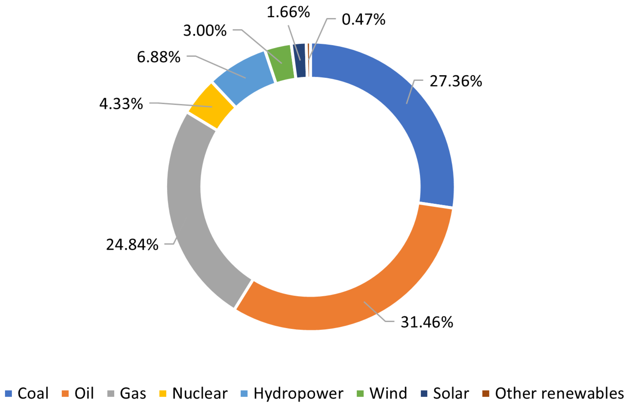
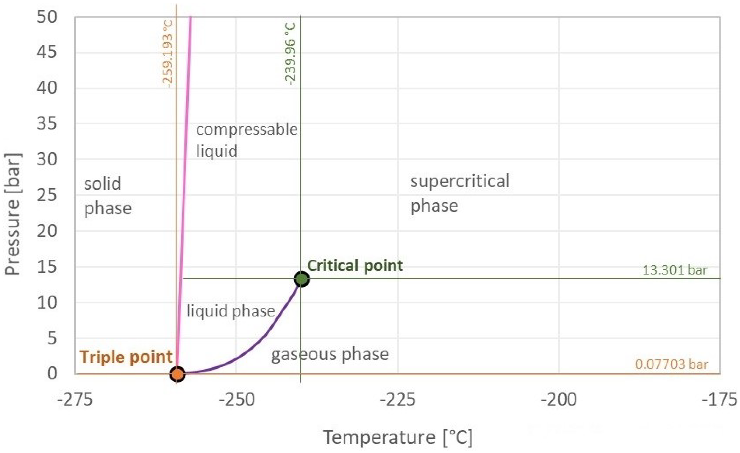
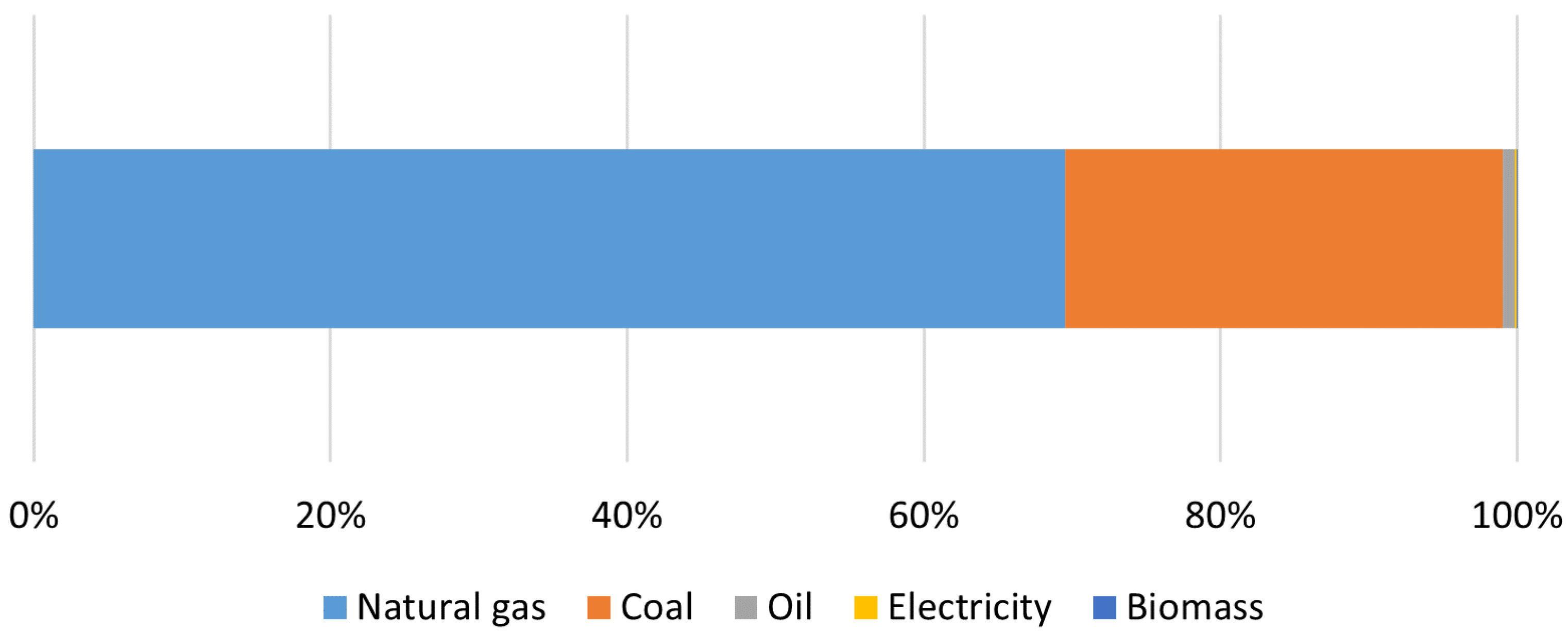
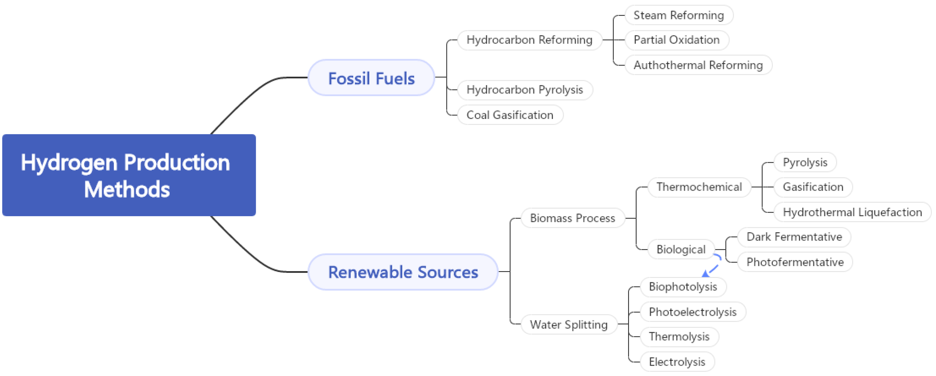
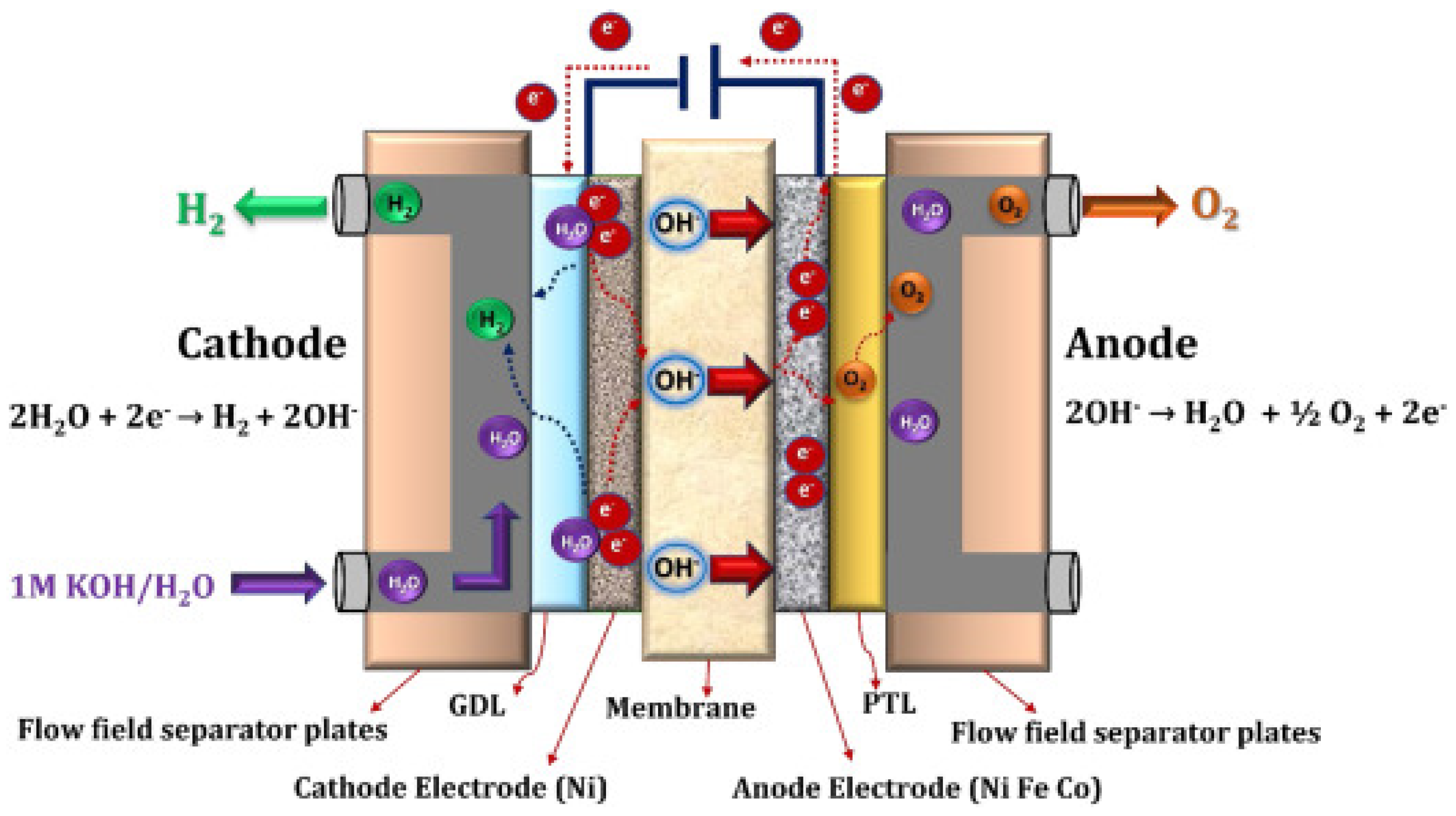
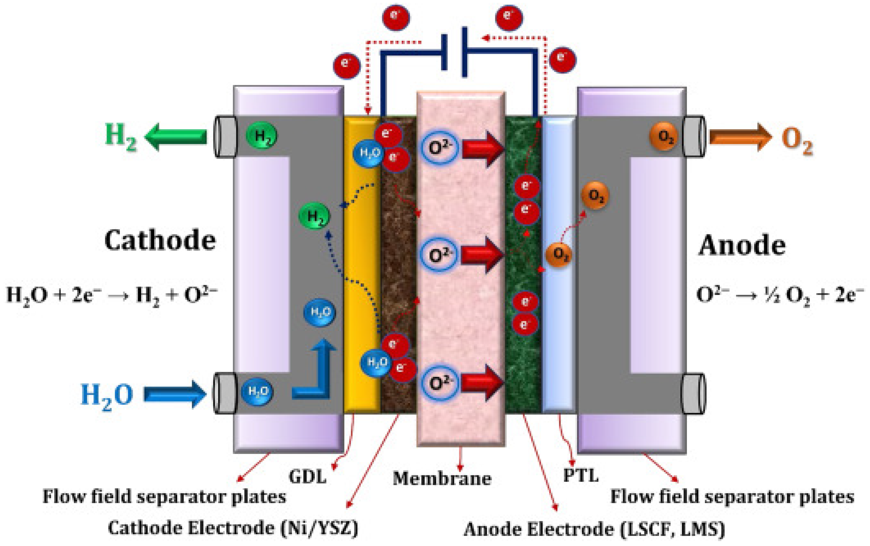
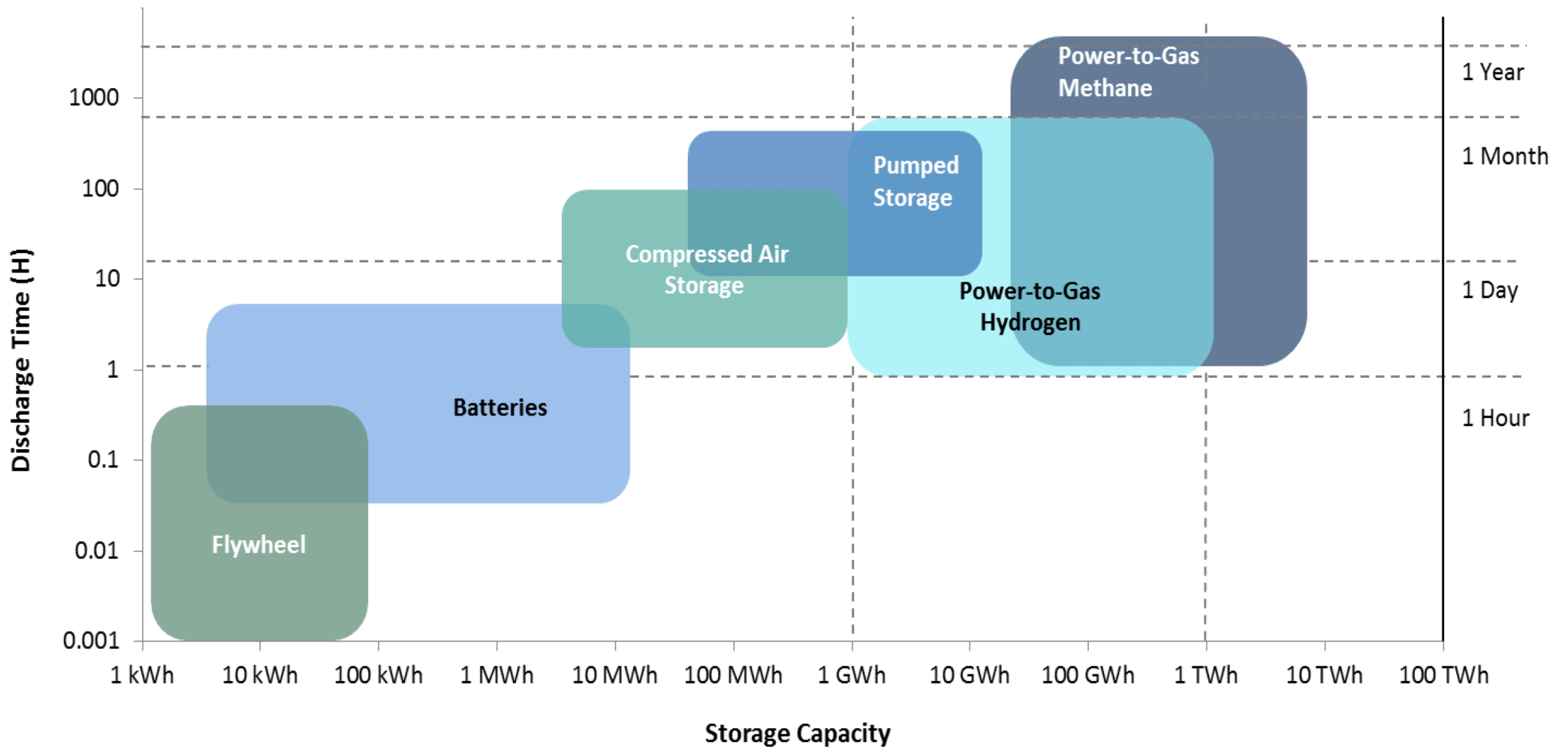
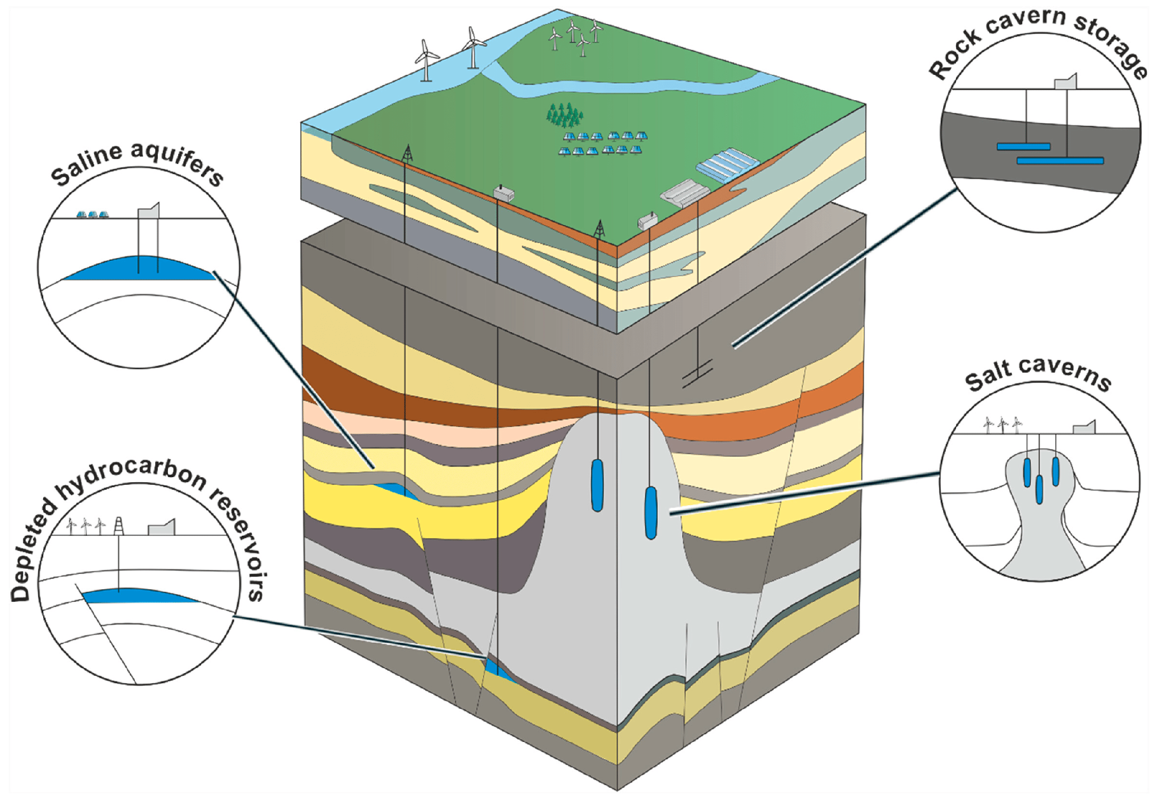
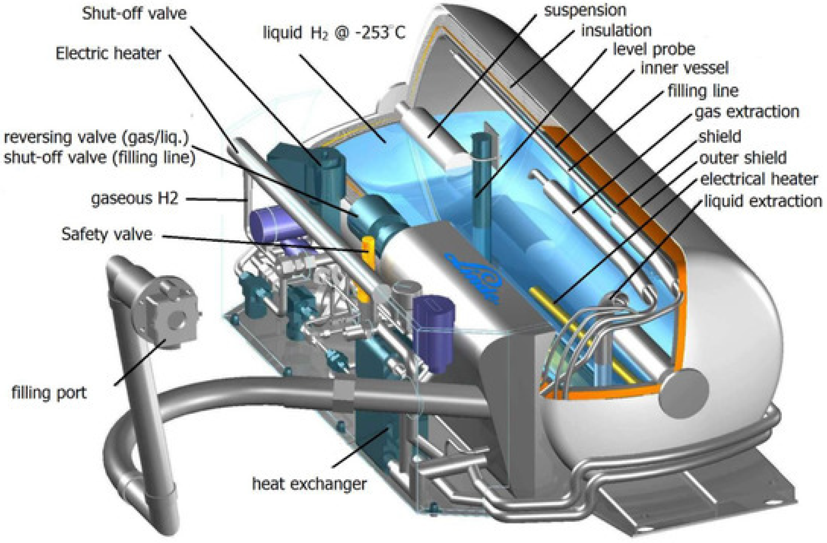
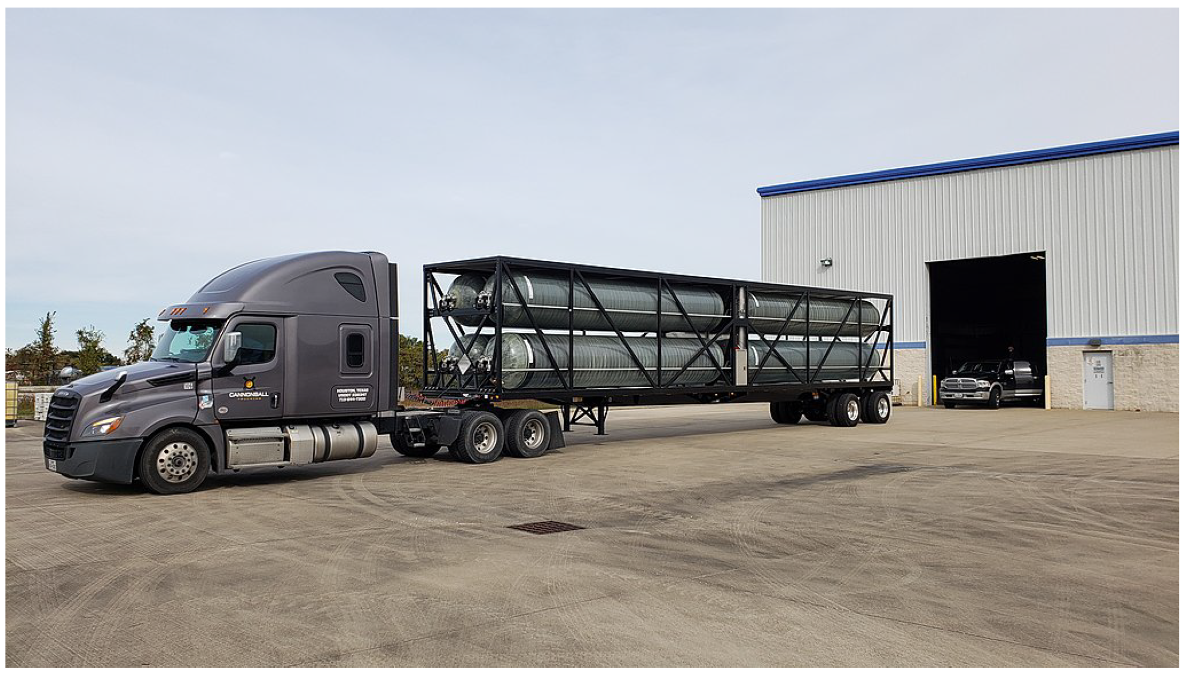
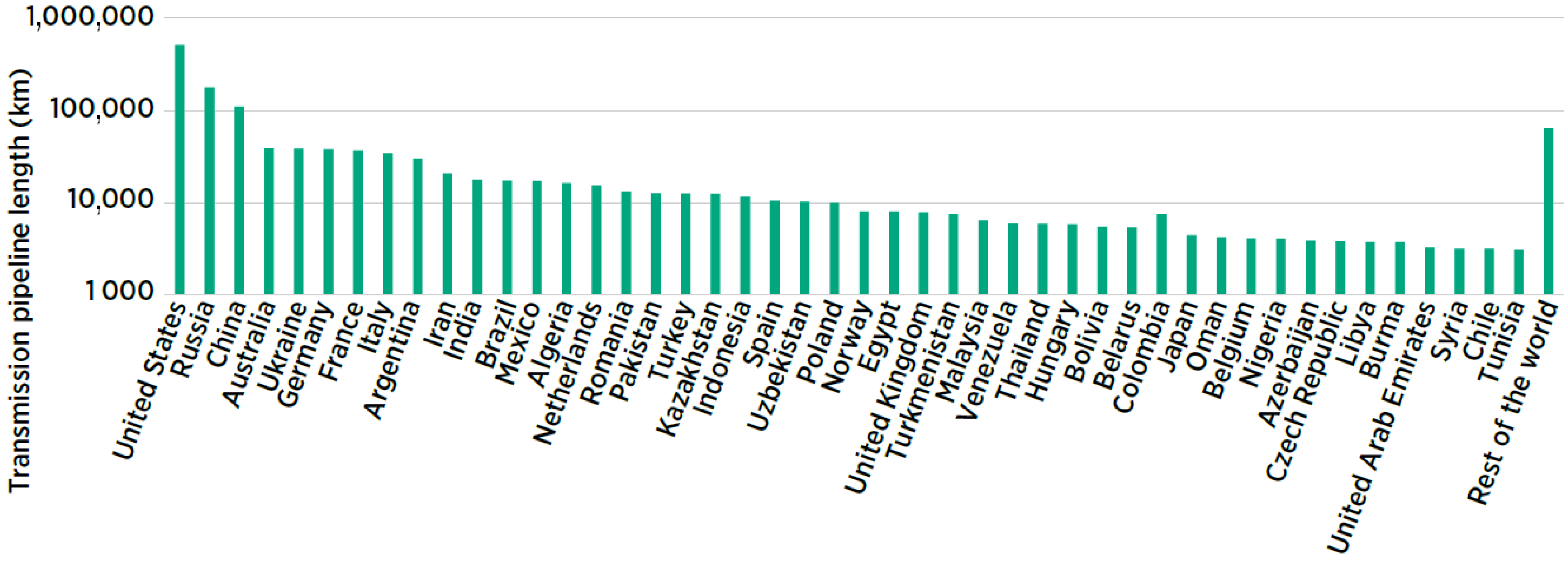
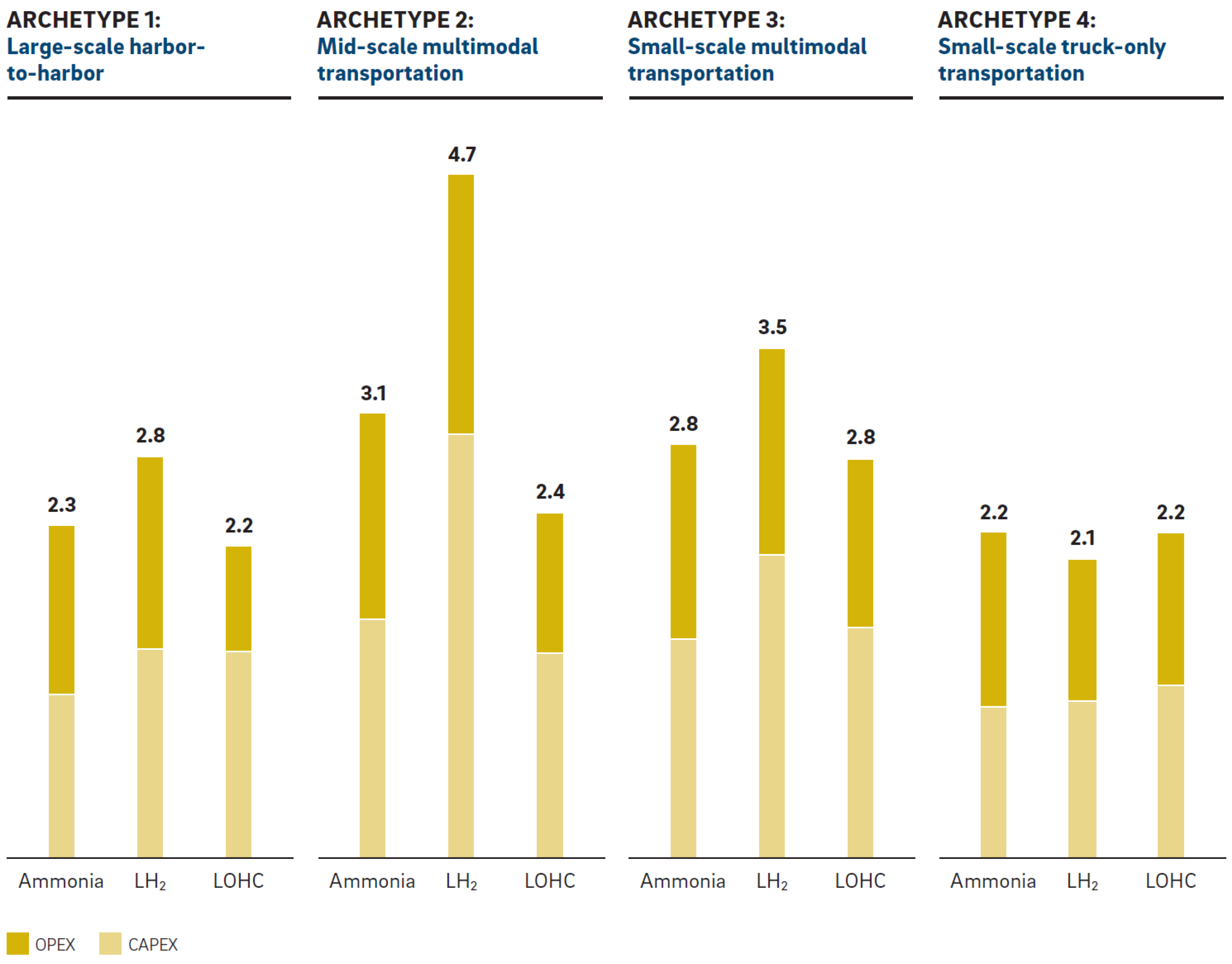
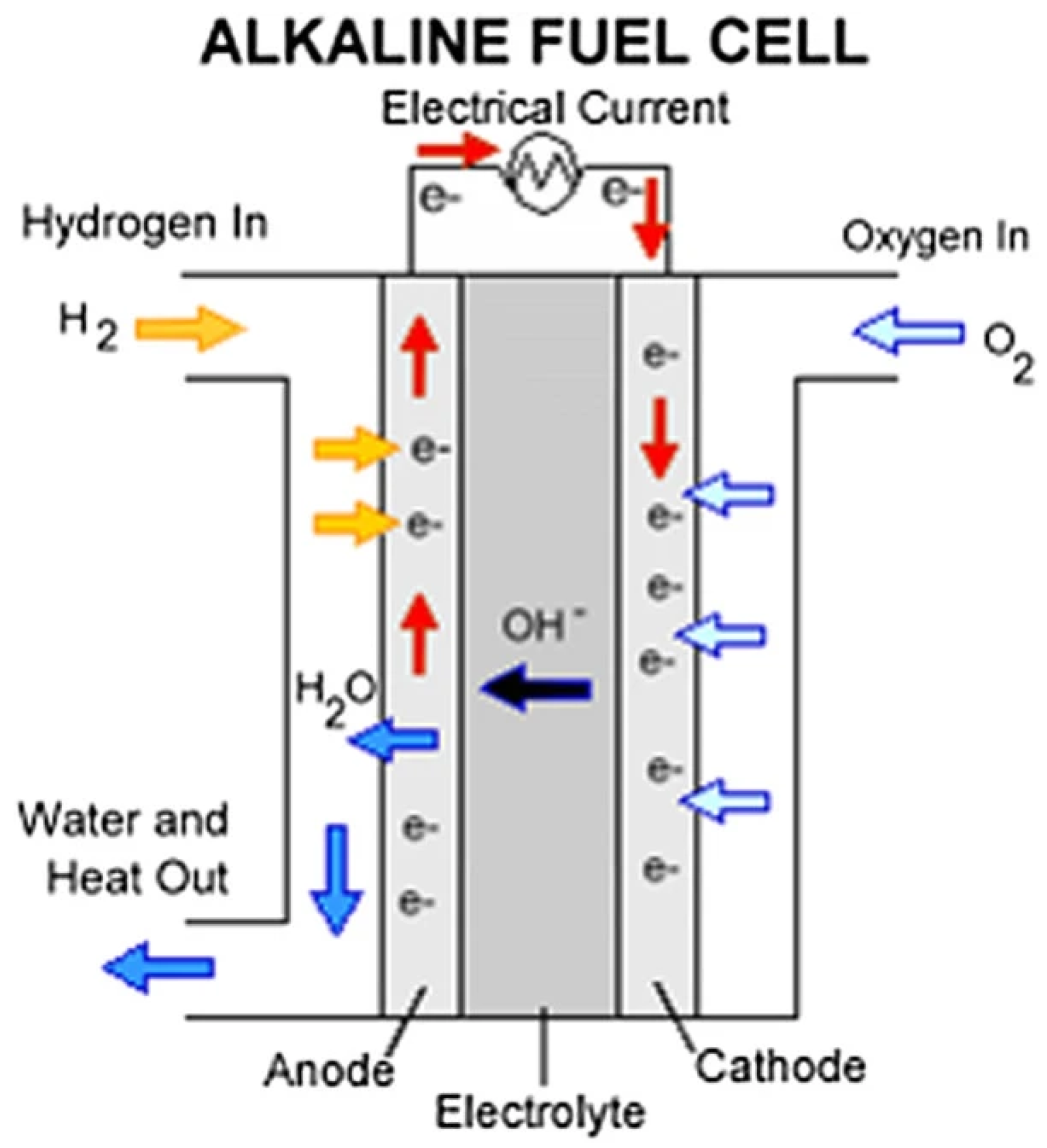
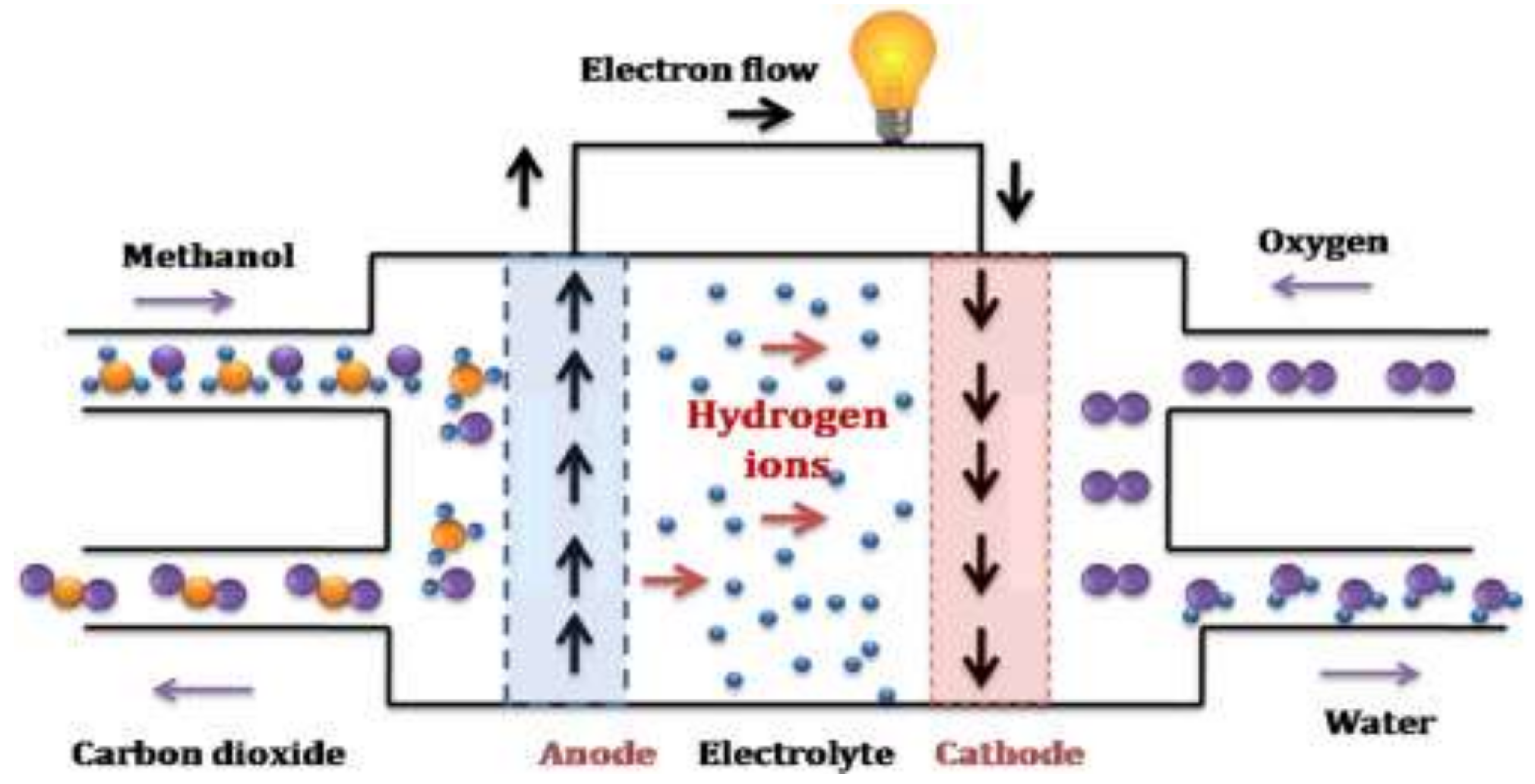
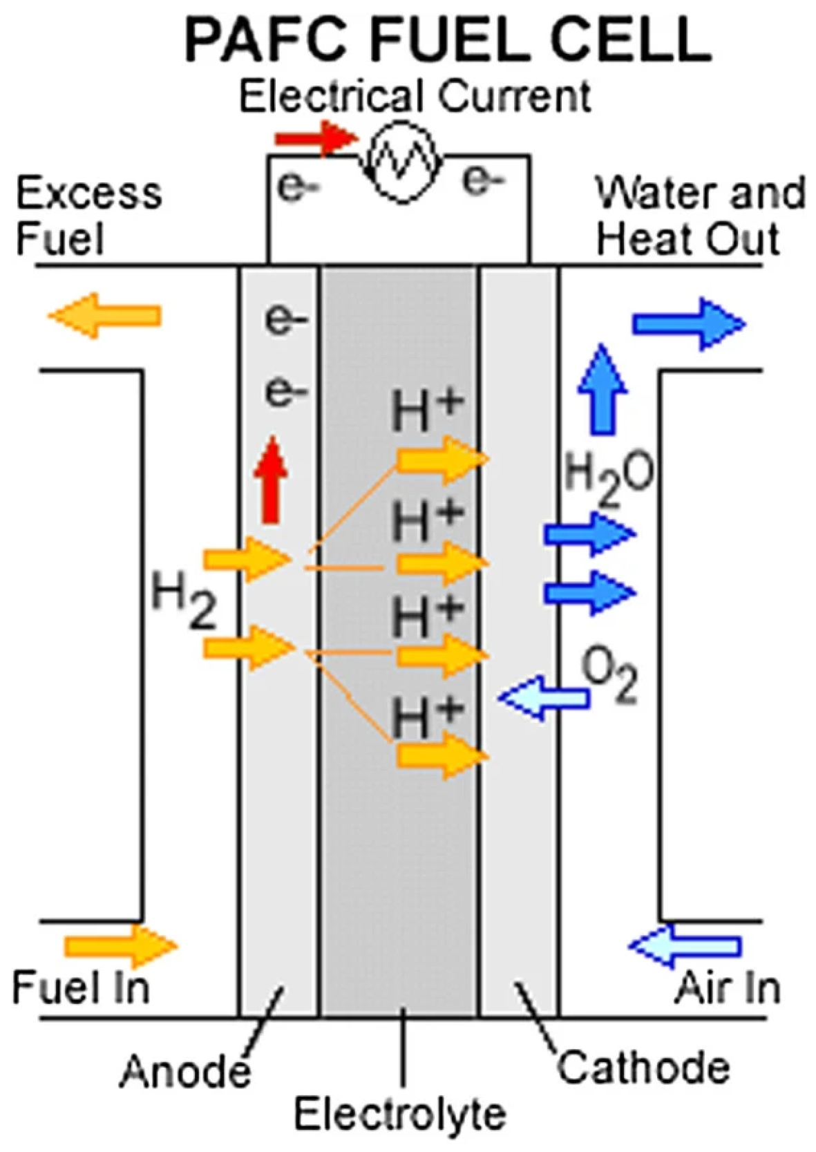
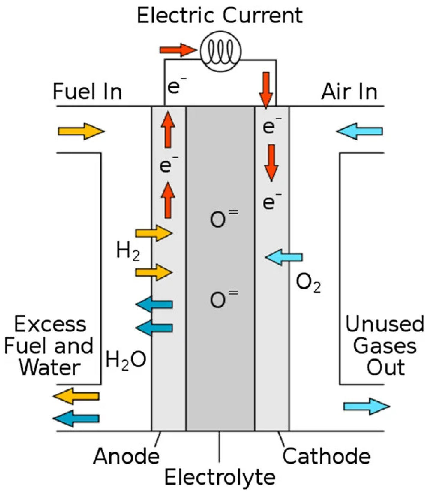
Table 1.
Main current manufacturers of alkaline electrolysers and their specifications.
| Company | Electrolyser Name | Pressure [bar] | H2 Capacity [Nm3/h] | Energy Consumption [kWh/Nm3] | Ref. |
|---|---|---|---|---|---|
| Nel Hydrogen (Oslo, Norway) | A3880 | 200 | 2400–3880 | 3.8–4.4 | [87] |
| Thyssenkrupp Nucera (Dortmund, Germany) | 20 MW AWE unit | 30 | 4000 | 4.5 | [88] |
| Cummins (Columbus, IN, USA) | HySTAT® 100-10 | 10 | 100 | 4.9–5.4 | [89] |
| McPhy (Grenoble, France) | McLyzer 800-30 | 30 | 800 | 4.5 | [90] |
| Sunfire (Dresden, Germany) | HyLink Alkaline | 30 | 2230 | 4.7 | [91] |
Table 2.
Main manufacturer of AEM electrolysers and their specifications.
| Company | Electrolyser Name | Pressure [bar] | H2 Capacity [Nm3/h] | Energy Consumption [kWh/Nm3] | Ref. |
|---|---|---|---|---|---|
| Enapter | AEM Multicore™ | 35 | 210 | 4.8 | [95] |
Table 3.
Main current manufacturers of PEM electrolysers and their specifications.
| Company | Electrolyser Name | Pressure [bar] | H2 Capacity [Nm3/h] | Energy Consumption [kWh/Nm3] | Ref. |
|---|---|---|---|---|---|
| Nel Hydrogen (Oslo, Norway) | M5000 | 30 | 4920 | 4.5 | [97] |
| ITM Power (Sheffield, UK) | HGas3SP | 30 | 400 | - | [98] |
| Cummins (Columbus, IN, USA) | HyLYZER® 4000-30 | 30 | 4000 | 5 | [89] |
| Siemens Energy (Munich, Germany) | Silyzer 300 | - | 1112–22,236 | - | [99] |
Table 4.
Main current manufacturers of solid oxide electrolysers and their specifications.
| Company | Electrolyser Name | Pressure [bar] | H2 Capacity [Nm3/h] | Energy Consumption [kWh/Nm3] | Ref. |
|---|---|---|---|---|---|
| Sunfire (Dresden, Germany) | HyLink SOEC | 3.5–5.5 | 750 | 3.6 | [101] |
| Topsoe (Lyngby, Denmark) | H2 SOEC 100 MW | 2 | 32,000 | 3.1 | [102] |
Table 5.
Technical characteristics of typical water electrolysis technologies: alkaline, proton exchange membrane, anion exchange membrane and solid oxide water electrolysis [12,79].
| Alkaline | AEM | PEM | Solid Oxide | |
|---|---|---|---|---|
| Electrolyte | KOH/NaOH (5–7 mol/L) | DVB polymer support with KOH/NaOH (1 mol/L) | PFSA membrane | YSZ |
| Separator | Asbestos, Zirfon, Ni | Fumatech | Nafion® | Solid electrolyte YSZ |
| Electrode/catalyst (oxygen side) | Nickel-coated perforated stainless steel | Nickel or NiFeCo alloys | Iridium oxide | Perovskites-type (LSCF, LSM) |
| Electrode/catalyst (hydrogen side) | Nickel-coated perforated stainless steel | Nickel | Platinum nanoparticles on carbon black | Ni-YSZ |
| PTL anode | Nickel mesh (not always present) | Nickel foam | Platinum-coated sintered porous titanium | Nickel mesh or foam |
| PTL cathode | Nickel mesh | Nickel foam or carbon cloth | Sintered porous titanium or carbon cloth | None |
| BP anode | Nickel-coated stainless steel | Nickel-coated stainless steel | Platinum-coated titanium | None |
| BP cathode | Nickel-coated stainless steel | Nickel-coated stainless steel | Gold-coated titanium | Cobalt-coated stainless steel |
| Operating temperature | 70–90 °C | 40–60 °C | 50–80 °C | 700–850 °C |
| Operating pressure | <30 bar | <35 bar | <30 bar | 1 bar |
| Nominal current density | 0.2–0.8 A/cm2 | 0.2–2 A/cm2 | 1–2 A/cm2 | 0.3–1 A/cm2 |
| Voltage range (limits) | 1.4–3.0 V | 1.4–2.0 V | 1.4–2.5 V | 1.0–1.5 V |
| Electrode area | 10,000–30,000 cm2 | <300 cm2 | 1500 cm2 | 200 cm2 |
| Efficiency | 50–68% | 52–67% | 50–68% | 75–85% |
| H2 purity | 99.9–99.9998% | 99.9–99.999% | 99.9–99.9999% | 99.9% |
| Lifetime (stack) | 60,000 h | >5000 h | 50,000–80,000 h | 20,000 h |
| Cold start | <50 min | <20 min | <20 min | >600 min |
| Stack unit size | 1 MW | 2.5 kW | 1 MW | 5 kW |
| Capital costs (stack) minimum 1 MW | 270 USD/kW | n.d. | 400 USD/kW | >2000 USD/kW |
| Capital costs (stack) minimum 10 MW | 500–1000 USD/kW | n.d. | 700–1400 USD/kW | n.d. |
| Development status | Early Adoption | Large Prototype | Early Adoption | Demonstration |
| TRL Scale | TRL 9 | TRL 6 | TRL 9 | TRL 7 |
n.d.—no data.
Table 6.
Classification of pressure vessels [109].
Table 6.
Classification of pressure vessels [109].
| Type 1 | Type 2 | Type 3 | Type 4 | Type 5 | |
|---|---|---|---|---|---|
| Components | All metal construction | Steel vessel with glass fibre composite | Full composite overwrap with metal (aluminium) liner | Full carbon fibre or carbon–glass fibre composite with HDPE liner and metallic boss | Full composite without liner |
| Structural load | Metal body withstands the whole load | Steel and composite materials share the load equally | The composite structure bears the most load, and the metal liner takes only about 5% mechanical load | Composite material carries the load | Composite material carries the load |
| Storage pressure | Up to 50 MPa | Highest pressure tolerance | Typically, around 45 MPa and showed problems for 70 MPa | Up to 100 MPa | Under development |
| Gravimetric density | ∼1 wt% | ≤2.1 wt% | ≤4.2 wt% | 4.4–5.7% | Under development |
| Weight | Relative weight is high | 30–40% less than Type I | Around half the weight of Type II | Lighter than Type III | It has the potential to be the lightest |
| Cost (differs with application) | 83 USD/kg H2 | 86 USD/kg H2 | 700 USD/kg H2 | 633 USD/kg H2 | Under development |
Table 7.
Comparative overview of the main geological options for underground hydrogen storage [131,132].
| Salt Caverns | Depleted Reservoirs | Aquifers | |
|---|---|---|---|
| Depth (m) | 300–1800 | 300–2700 | 400–2300 |
| Operating pressure (bar) | 35–270 | 15–285 | 30–315 |
| Safety | Very good | Poor | Poor |
| Relative Investment Cost | Low | Low | Low |
| Relative Operational Cost | Low | Moderate | Low |
| Injection rate | Moderate | High | Moderate |
| Withdrawal rate | Moderate | High | Moderate |
| Working/Total gas capacity | High | Moderate | Low |
| Feasible cycles per annum | High | Low | Low |
| Current locations | UK and USA | None for H2 Established use with NG | None for H2 Established use with NG |
| Suitability for H2 | Proven | Still under investigation. Proven for town gas with up to 50% of H2. | Under investigation. Proven for CH4 with up to 10% of H2. |
| Technology Maturity | Early Adoption | Small Prototype | Concept |
| TRL Scale | 9–10 | 4 | 3 |
Table 8.
Technical characteristics of physical and material-based hydrogen storage technologies [106,111,130,133].
| H2 Storage System | Gravimetric Energy Density, kWh/kg (System) | Gravimetric Energy Density, kWh/kg (Pure Substance) | Volumetric Energy Density, g/L (System) | Volumetric Energy Density, g/L (Pure Substance) | Technology Maturity | TRL Scale | |
|---|---|---|---|---|---|---|---|
| Compressed gas | Type III 35 MPa | 1.9 | 33.3 | 0.5 | 0.8 | Mature | 11 |
| Type III 70 MPa | 1.0 | 33.3 | 0.7 | 1.3 | Mature | 11 | |
| Type IV 70 MPa | 1.6 | 33.3 | 0.7 | 1.3 | Mature | 11 | |
| Liquid | LH2 | 2.0 | 33.3 | 1.2 | 2.2 | Demonstration | 7–9 |
| Cryo- compressed | CcH2 | 2.5 | 33.3 | 1.5 | 2.7 | Demonstration | 6–7 |
| Adsorbent | MOF-5 | 1.0 | 2.7 | 0.7 | 1.8 | Concept | 2–3 |
| Metal hydride | MgH2 | 0.7 | 2.5 | 1.2 | 3.7 | Demonstration | 6–7 |
| TiFe | 0.3 | 0.6 | 0.6 | 4.1 | Large Prototype | 5–6 | |
| TiMn2 | 0.4 | 0.6 | 1.3 | 4.0 | Large Prototype | 5–6 | |
| Complex hydride | Mg(BH4)2 | - | 5.0 | - | 4.9 | Concept | 1–2 |
| NaAIH4 | - | 2.5 | - | 3.1 | Concept | 1–2 | |
| LOHC | N-ethyl carbazole | - | 1.7 | - | 2.2 | Demonstration | 6–7 |
| Dibenzyl toluene | - | 2.0 | - | 1.9 | Demonstration | 7–8 |
Table 9.
Comparison between hydrogen operating ICE, gas turbines and fuel cells [138].
Table 9.
Comparison between hydrogen operating ICE, gas turbines and fuel cells [138].
| ICE | Gas Turbine | PEMFC | SOFC | |
|---|---|---|---|---|
| Conversion efficiency | 50% | 35% | 52% | 60% |
| System efficiency | 50% | 58% | 56% | 80% |
| Cost (USD/kW) | <500 | – | >1500 | >4500 |
| Partial load efficiency | High | Low | High | High |
| Tolerance to load variations | High | High | Medium | Low |
| Lifetime | High | High | Low | Low |
| Noise/vibration | High | High | Low | Low |
| NOx, CO and hydrocarbon emissions | Medium | Medium | Low | Low |
| Technology Maturity | High | High | Medium | Low |
| TRL Scale | 9 | 8 | 9 | 8 |
Table 10.
Technical characteristics of fuel cell technologies: alkaline, proton exchange membrane, direct methanol, phosphoric acid, molten carbonate, and solid oxide fuel cell [18,67,159,178].
| Fuel Cell Type | AFC | PEMFC | DMFC | PAFC | MCFC | SOFC |
|---|---|---|---|---|---|---|
| Temperature °C | 90–100 | 50–100 | 60–200 | 150–200 | 600–700 | 600–1000 |
| Electrolyte | Potassium hydroxide | Polymer membrane | Polymer membrane | Phosphoric acid | Carbonate melt | Solid ceramic oxide |
| Power range | 1 kW to 100 kW | 1 W to 100 kW | 1 W to 100 kW | 200 kW to 10 MW | 500 kW to 10 MW | 1 kW to 2 MW |
| Fuel | Purest H2 | Pure H2 | CH3OH + H2O | H2, COCH3OH | H2, CO, CH4 | H2, CO2CH4 |
| Efficiency | 40–55% | 40–55% | 50–70% | 40–55% | 50–60% | 40–72% |
| Startup time | <5 min | <5 min | <5 min | 1–4 h | 5–10 h | 5–10 h |
| Investment costs USD/kW | 200 to 700 | 3000 to 4000 (stationary) 500 (mobile) | n.a. | 4000 to 5000 | 4000 to 6000 | 3000 to 4000 |
| Life expectancy | 4000 to 8000 h | 60,000 h (stationary) 5000 h (mobile) | n.a. | 30,000 to 60,000 h | 20,000 to 40,000 h | <90,000 h |
| Market development | Early Adoption | Early Adoption | Large Prototype | Demonstration | Demonstration | Demonstration |
| TRL scale | 10 | 9 | 6 | 8 | 7 | 8 |
Disclaimer/Publisher’s Note: The statements, opinions and data contained in all publications are solely those of the individual author(s) and contributor(s) and not of MDPI and/or the editor(s). MDPI and/or the editor(s) disclaim responsibility for any injury to people or property resulting from any ideas, methods, instructions or products referred to in the content. |
© 2023 by the authors. Licensee MDPI, Basel, Switzerland. This article is an open access article distributed under the terms and conditions of the Creative Commons Attribution (CC BY) license (https://creativecommons.org/licenses/by/4.0/).
Share and Cite
MDPI and ACS Style
Rolo, I.; Costa, V.A.F.; Brito, F.P. Hydrogen-Based Energy Systems: Current Technology Development Status, Opportunities and Challenges. Energies 2024, 17, 180. https://doi.org/10.3390/en17010180
AMA Style
Rolo I, Costa VAF, Brito FP. Hydrogen-Based Energy Systems: Current Technology Development Status, Opportunities and Challenges. Energies. 2024; 17(1):180. https://doi.org/10.3390/en17010180
Chicago/Turabian StyleRolo, Inês, Vítor A. F. Costa, and Francisco P. Brito. 2024. "Hydrogen-Based Energy Systems: Current Technology Development Status, Opportunities and Challenges" Energies 17, no. 1: 180. https://doi.org/10.3390/en17010180
Note that from the first issue of 2016, this journal uses article numbers instead of page numbers. See further details here.