Article

Comprehensive Investigation of the Thermal Performance of an Electrically Heated Double-Glazed Window: A Theoretical and Experimental Approach

1
Institute of Engineering Thermophysics of the National Academy of Sciences of Ukraine, 03057 Kiev, Ukraine
2
Department of Building Physics and Renewable Energy, Kielce University of Technology, Aleja Tysiąclecia Państwa Polskiego, 7, 25-314 Kielce, Poland
*
Author to whom correspondence should be addressed.
Energies 2024, 17(17), 4491; https://doi.org/10.3390/en17174491
Submission received: 27 July 2024 / Revised: 27 August 2024 / Accepted: 3 September 2024 / Published: 6 September 2024
(This article belongs to the Section G: Energy and Buildings)

Abstract

:
The thermal performance of windows is an important area of research to reduce the energy consumption of buildings and improve indoor comfort. The application of innovative glazing technologies can improve the energy performance of windows and transparent facades, resulting in significant energy savings. This paper presents research results on the energy performance of electrically heated windows. A comprehensive CFD and experimental analysis of the heat transfer processes in a window space depending on the size, power, and location of an electric heater was performed. The convective gas flows in the gas gaps and in the boundary layer were also analysed, and it is shown that a window with an electric heater can reduce the energy consumption of a room by 10–12%. This study is a pilot study to assess the feasibility and cost-effectiveness of electric local heating of a window or facade to minimise heat loss before full-scale implementation. The results of numerical modelling and experimental studies confirm the potential of the new technologies.

1. Introduction

In the mid-20th century, window designs transitioned from wooden frames and single-pane glass to double-glazed units, significantly enhancing the thermal insulation properties of these transparent structures, which are integral components of any building or structure. A double-glazed unit is a sealed construction consisting of glass panes of the same or different thicknesses separated by spacer bars, forming airtight chambers between the glass panes filled with air or an inert gas. Gaskets, sealants, and moisture-absorbing substances seal the components of modern double-glazed units along their entire perimeters.
Since the sale of the first plastic window in 1959, manufacturers and researchers have dedicated significant efforts to improving the thermal insulation properties and energy efficiency of transparent structures in general and window constructions in particular. Many studies have been carried out to find out which window elements influence the energy efficiency of a building and how they can be improved. Researchers have mainly focused their efforts on the thermal and optical properties of window systems, their geometry, shape, and orientation, e.g., [1,2,3]. The authors of [4,5,6] considered the effectiveness of new materials with improved properties: chromogenic and translucent photovoltaic materials, as well as insulating and phase-change materials, which can also increase the thermal resistance of windows. In [7], 48 window configurations with insulating spacer frames at the edge of the glazing were studied, and it was shown that the thermal resistance of the window was improved by an average of 13%. However, according to the authors, the main reason for the huge energy losses in buildings remains the high thermal conductivity of windows. Today, double- and triple-chambered double-glazed units have emerged in window designs, distinguished by the number of glass panes and the space between them. For instance, a three-chambered double-glazed unit structurally consists of four glass panes and three interpane chambers, interconnected by spacer bars with a moisture absorber and sealant. Moreover, spacer bars and glass panes, within a specific window construction, can have different frame dimensions and glass-pane thicknesses. These design features undoubtedly lead to an increase in the thermal resistance of the windows, which, nevertheless, remains significantly lower than the thermal resistance of the wall sections of facades.
The 1990s marked a pivotal era in the quest for energy-efficient window designs with the advent of low-emissivity (low-E) glass, which can reduce thermal energy costs by up to 3% [8,9]. At the same time, the authors claim that the required level of comfort is not achieved during the day. In [10,11], the authors show that it is possible to improve this situation by using emission filters. Pioneered by researchers at the Lawrence Berkeley National Laboratory and South wall Technologies in the United States, these innovative coatings, known as k-films and i-films, can be applied to the surface of glass with thicknesses of mere hundredths of a millimetre.
Low-E coatings primarily target the radiative component of heat transfer from indoor spaces to the surrounding environment. They selectively allow short-wave solar radiation to pass through, warming the interior while effectively reflecting long-wave thermal radiation back into the room. This remarkable property significantly reduces heat loss, minimising the energy consumption required to maintain comfortable indoor temperatures [12,13]. The authors conclude that the use of multilayer systems of environmentally stable glass with low-E-type coatings can protect against solar heat radiation without interrupting visible light (i.e., without impairing visibility), but no information is given on the thermal performance of such windows. The papers [14,15] provide data on an innovative translucent photoluminescent coating for smart windows. In the context of building applications, this coating significantly improves visual comfort by providing an even distribution of daylight and mitigating excessive solar gain. This line of research aims to improve visual comfort without considering the energy performance of windows.
In addition to the radiative component of heat transfer through window panes, researchers have focused on the conductive component. In [16,17], it is shown that controlling the convective component of heat transfer at a window-to-floor area ratio of 10% can reduce the heating demand of the building by about 2.2 W/m2 floor area at an external air temperature of −20 °C. However, in this case we are talking about forced air convection without analysing the parameters of the convective flow. The authors of [18,19] developed a method for estimating the heat transfer coefficient of a window based on the low E values at the surface and the inert gas slit content. Filling the interpane space in double-glazed units with inert gases, which have lower thermal conductivity than air, can effectively reduce conductive heat transfer. Moreover, the emergence of novel materials such as aerogel, with a thermal conductivity 2–3 times lower than that of air, has the potential to virtually eliminate the conductive component of heat transfer through glazing units [20,21,22]. The use of vacuum-insulated glass units assumes the absence of convection within the glass units [23,24]. The authors have shown that vacuum windows reduce the thermal energy demand of a building, giving a theoretical heat transfer coefficient of 0.810–0.831 W/m2K. However, these constructions are particularly sensitive to window orientation and window-to-wall ratios. In general, heat transfer through transparent structures is influenced by various factors, including the following:
Time-varying climatic factors: changes in external air temperature, humidity, and solar radiation intensity significantly impact heat transfer;
Geometric characteristics: the size, shape, and orientation of windows affect the amount of solar radiation absorbed and heat transfer;
Frame design: the material properties and thermal insulation of window frames play a crucial role in heat transfer;
Low-emissivity coating properties: the type and effectiveness of low-E coatings significantly influence heat transfer;
Moisture condensation: condensation on glass surfaces and other structural components can alter thermal insulation and affect the overall performance of the glazing system.
This issue is particularly pronounced in single-glazed units. Even with low-E coatings, condensation can still occur in the edge zones of double-glazed units, especially if the seal is compromised.
To address these challenges, researchers have explored the use of internal energy sources within the interpane space of double-glazed units, either on the glass surfaces or within the spacer bars [25,26,27]. According to Framex [28], a company that specialises in energy-efficient glazing, such units can enhance energy-saving properties by 10–12%, reduce edge zone frosting by 50%, lower heating and cooling costs by 5–7%, and contribute to a more comfortable and healthier indoor environment.
Recently, heated windows have gained significant attention as a potential energy-efficient solution [29,30]. As an alternative to typical window glazing, low-emissivity coatings, gas-filled windows, vacuum windows, and double or triple glazing can be used. In addition, heating technology can be combined with these types of glazing to provide a better solution to the problems mentioned above [31,32,33]. Although electrically heated glass surfaces were initially used primarily to prevent condensation [34,35,36], research has also demonstrated the potential energy-efficiency benefits of heated glazing systems [37]. Studies have shown that energy savings of up to 13% can be achieved by installing heated glazing on the north or east sides of buildings. Published papers propose technical solutions where the heating element is an electrically conductive coating on the glass surface. In this way, the surface temperature can be higher compared to glass without heating. However, the convective heat transfer processes and energy characteristics are not taken into account in these works.
It is important to consider that heating windows also increases heat loss through the glass surface. However, the temperature difference between the indoor environment and the window can be minimised, reducing overall heat loss from the building. Windows with electric heaters installed in localised areas of the window space are not currently used. However, as shown in this paper, localised heating of the gas and/or structural elements of the window can affect the energy performance of this envelope and therefore its thermal resistance. Available publications provide information on new window designs with heating foils applied to the glass surface. However, there are no theoretical or experimental studies on the influence of design or energy factors on the thermal resistance of a glazing unit. Therefore, the aim of this paper is to investigate such dependencies and to model different situations of local heating in the conditions of window application. In this regard, the question of the effectiveness of heated windows and their optimal energy parameters remains unresolved, which in this work was decisive for us when performing theoretical and experimental studies.
The purpose of the work was to investigate the temperature state and thermophysical characteristics of heat transfer through a double-glazed unit with an internal energy source in the interglacial space in a comparative assessment with a similar double-glazed unit without a heat source and to compare the self-efficiency of windows with a heater.

2. Materials and Methods

2.1. Experimental Investigations of Heated Windows

To precisely analyse heat transfer in heated windows, a comprehensive experimental setup was established within a climate chamber at the Kielce University of Technology’s Heat and Mass Transfer Laboratory. This setup enabled one to precisely control temperatures and measure heat flow distributions across heated window surfaces. Figure 1 shows a diagram and photographs of the measuring stand.
The air parameters and its velocity were set in a measuring climate chamber. The studies took into account the stabilised state of the microclimate in the chamber from inside and outside. Heat flux sensors were installed on the surfaces of heated windows, and temperature sensors were installed inside the window to control the temperature and heat flux over the window surface from the outside and inside, as well as in the window section. The heated windows had three-chamber argon-filled packages (gap width L = 18 mm, ε = 0.17). For comparison, ordinary windows of similar design, filled with air, were also tested under the same conditions.
Inside, between the panes, thermocouples with a measured temperature range of −30 °C to +40 °C, an accuracy of 0.1 °C, and a digital four-channel thermometer (TM-947SD) with a data logger (Lutron, TMS Europe Ltd., Bradwell, UK) with a resolution of 0.1 were installed. The locations of the thermocouples are shown in Figure 1b. To measure the heat flux density on the surface of the glasses, foil heat flux sensors (FHF0) with a sensitivity of Φi = 10.84 µV/(W/m2) were fixed, measuring local values of the parameter. The FHF04 sensors showed heat flux values that took into account conduction, radiation, and convection in the temperature range from −70 to +120 °C. The LI19 (Hukseflux, New York, NY, USA) data logger (HuksefluxChina China Beijing Haoxael Technology Co., Ltd., Beijing, China) displayed the minimum, maximum, and average heat flux values, dates, and measurement durations (error = 0.1%).
The tests in the climate chamber were carried out at a stabilised indoor temperature Tv = 20 °C, 50% humidity, and at outdoor temperatures that varied in the range of −20 °C to +5 °C with a step of 5 °C. Measurements were carried out according to [38]. The data obtained were later used to verify the calculated energy parameters of the windows. To study various modifications of the window and heater temperatures, a mathematical model was developed, a description of which is given below.
It follows from the data presented that at an external temperature of 0 °C, the heat flux is directed both into the room and outside. It is obvious that by reducing the temperature of the heater, it is possible to achieve zero heat balance of the window, and, consequently, eliminate heat loss through the glazing. The outer glass loses more heat at any heater temperature compared to the window without a heater. That is, the positive effect for a room, which was reported by the authors of previous works, can be achieved by using additional energy sources or accumulating it, as shown in the works [39,40]. An innovative approach has been used in the development of a combined window system [41,42], which combines thermochromic and radiant cooling technologies. In addition, self-powered smart windows utilise photovoltaic technology to eliminate dependence on external power, demonstrating the potential for sustainable solutions for buildings [43]. Optimisation of the design and energy parameters of the heating glass can be performed using numerical modelling for various conditions of window application.

2.2. Theoretical Studies of a Heated Window

Unfortunately, the available data on the thermal insulation efficiency of window panes with an energy source in the interglass space are limited or do not correspond to reality. Therefore, a study was conducted on the temperature state and thermophysical characteristics of window panes with an internal energy source in the interglass space during heat transfer from the room to the environment, and a comparative assessment was made with a similar window pane without a heat source. The results of these studies are presented in this article.
Our research is based on [44,45], which present a basic mathematical model for the thermal conductivity of a window.
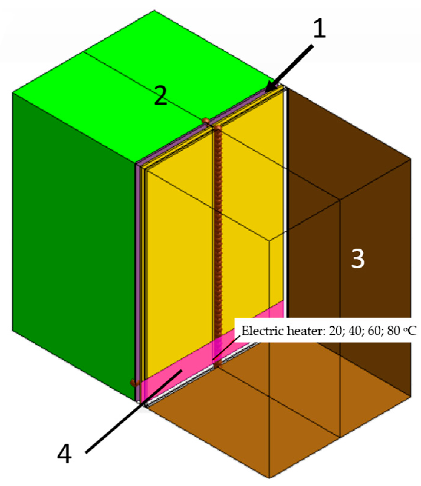
It is known that the most accurate theoretical studies of heat exchange processes of various structures with the environment is carried out using CFD modelling. Modelling involves the study of the mutual influence of specific parameters on the energy performance of windows. For example, in [46,47], the heat transfer process through a window is modelled in order to study the influence of the air-gap thickness on the thermal resistance. Verification of the model shows good agreement between calculated and experimental data. The authors of [48] modelled the heat transfer between parallel surfaces of an enclosed space, establishing the main regularities in the variation in Nusselt numbers, which will be used in this paper. In [49,50], comfort conditions with the lowest energy input were studied using software tools to select the optimal solution. There are no studies in the literature dedicated to the modelling and experimental verification of windows with electric local heating. In our theoretical studies, a physical model of a window was used, which is shown in Figure 2. On one side of the window pane, the air temperature was maintained at the level of −20 °C, and on the other side at +20 °C. The area of the climate chamber with a temperature of −20 °C was defined as the environment, with a temperature of +20 °C as part of the inner room (Figure 2).
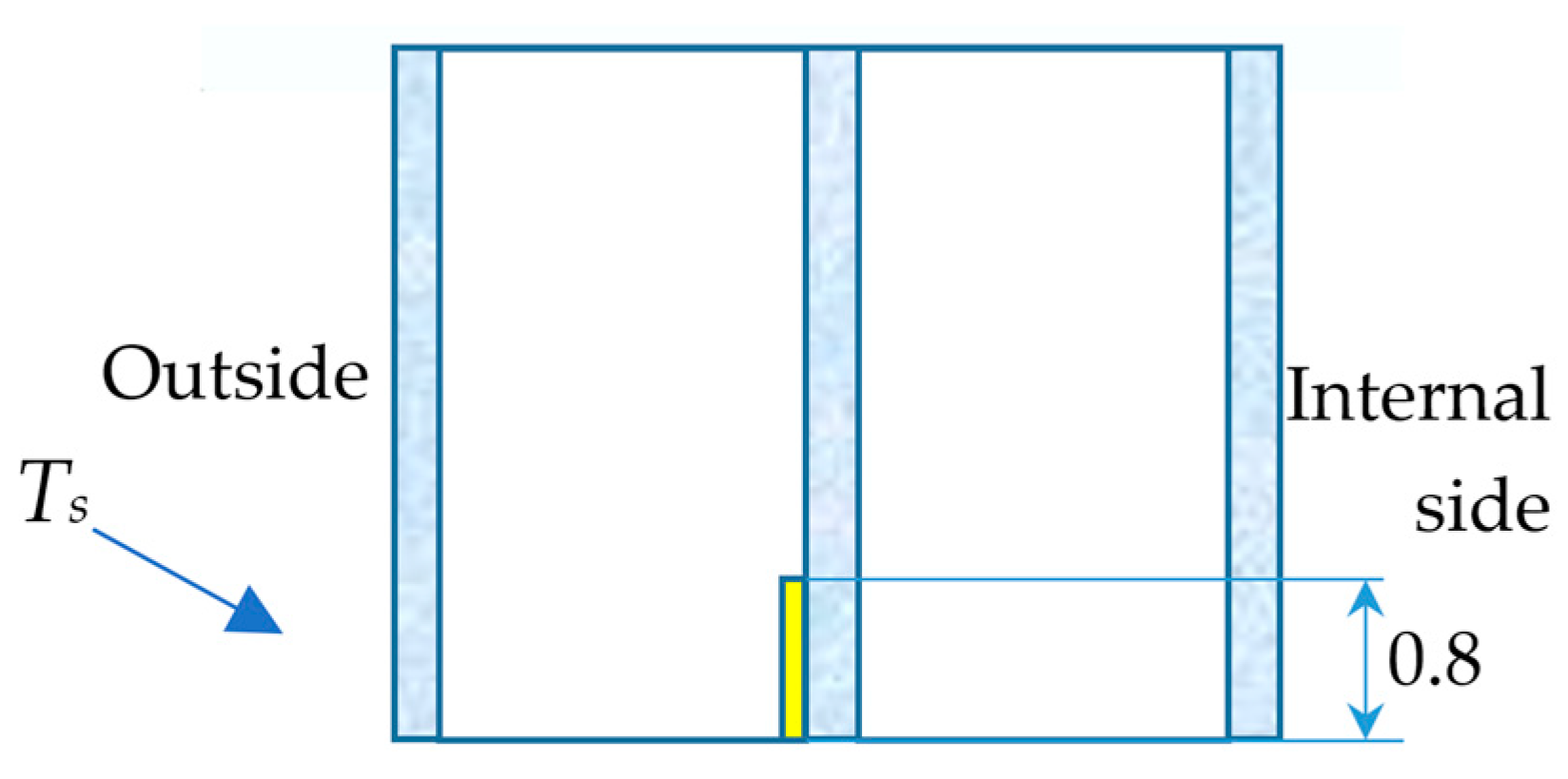
The glass panes in the window pane were made of ordinary glass without energy-saving films. The interglass space of the window pane was filled with argon. The rectangular computational grid of the CFD model contained more than 2,750,000 elements. The heat source, in the form of a thin conductive film, was located in the lower part of the middle glass of the window pane on the surface closest to the warm part of the climate chamber, shown in Figure 3. The power of the source in the modelling process was determined by the temperature level: 40, 60, or 80 °C.
The three-dimensional CFD model (Figure 2) considers heat transfer from the room to the environment at different power levels of the energy source to determine the thermal parameters of the window pane. Heat transfer from the room to the external environment occurs through conduction, convection, and long-wave radiation. The magnitudes of the corresponding heat fluxes depend on the temperature difference inside the room (Tin) and in the external environment (Tout) (Figure 3).
Momentum and energy transfer processes in the presented CFD model are considered in a three-dimensional formulation and are described by a system of differential equations: the continuity equation; the Navier–Stokes equations, the energy equation, the heat conduction equation, and the ideal gas equation.
Coupling conditions are implemented on the “solid–air” and “solid–solid” interface surfaces.
The CFD model consists of two relatively large areas: the air part of the warm part of the climate chamber—AirIN—and the air part of the cold part of the chamber—AirOUT. These areas are separated by a double-glazed window (Figure 2). The presence of large and thin objects in the model does not allow us to build a single computational mesh for the model as a whole. Therefore, a computational mesh for thin objects with ten layers in the gaps between the glass surfaces and a base size of 0.006 m was used for the glass panes and the interglass space. In the areas occupied by the air of the chamber, a conventional rectangular mesh with five prismatic layers near the surfaces of the areas and a base size of 0.01 m was constructed.
It is known that the turbulent boundary layer under natural convection has a Rayleigh number approaching the value of Ra = 109 − 1011. In the case of natural convection in the interglass space of modern double-glazed windows, the Rayleigh number does not exceed Ra = 106 [45]. Therefore, when calculating heat transfer under natural convection, the laminar flow regime is used. And the laminar flow regime does not involve the calculation of the wall function. The boundary conditions are given in Table 1.
Figure 4 presents the other boundary conditions of the CFD model, which in our opinion, correspond to the conditions of the climate chamber.
Fixed temperatures of –20 °C and 20 °C were established on the vertical surfaces of the air parts of the model opposite the window-pane surfaces.
In the process of modelling heat transfer through a two-chamber window pane with a heat source in the interglass space, various options were considered (Table 2).
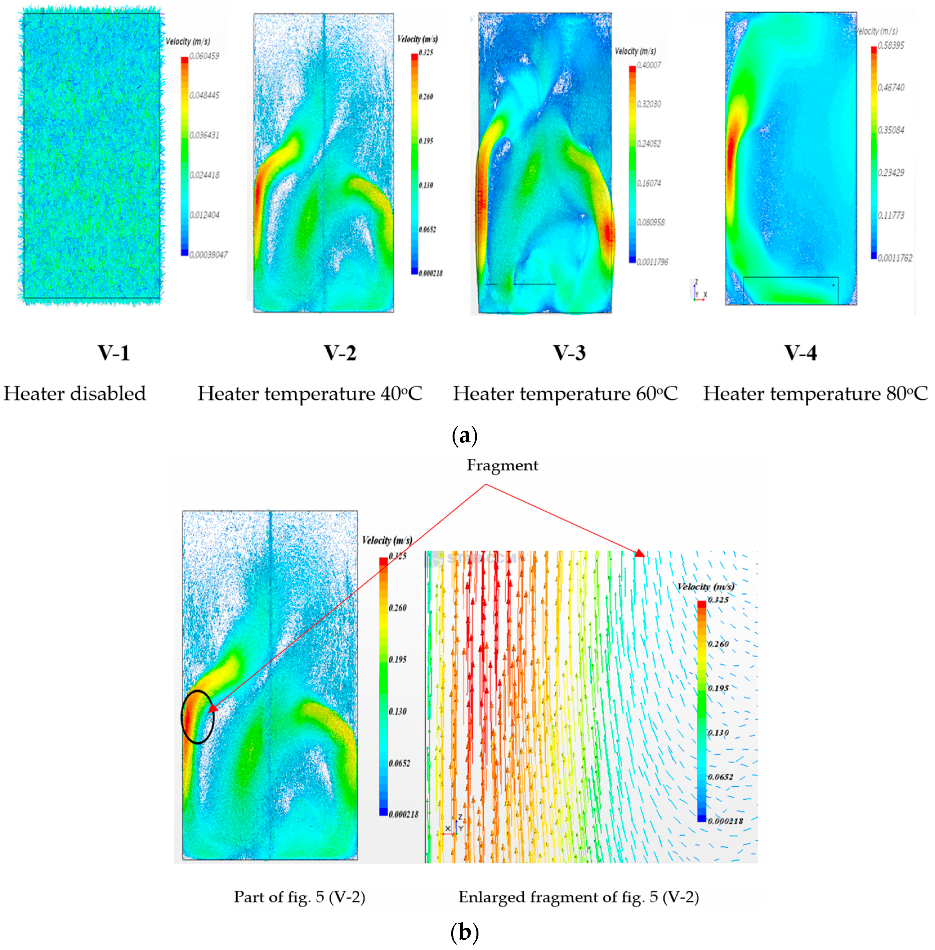
Figure 5 shows the velocity fields of argon in the interglass space of a window pane that is close to the cold side of the climatic chamber.
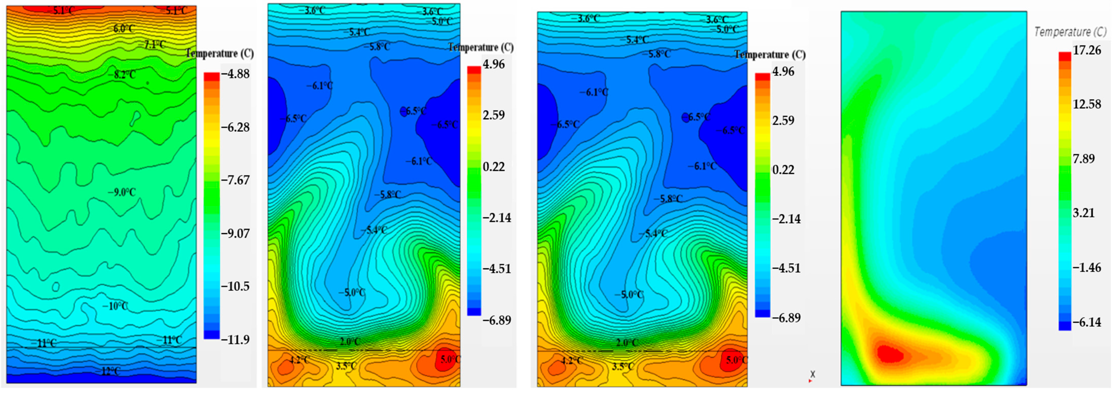
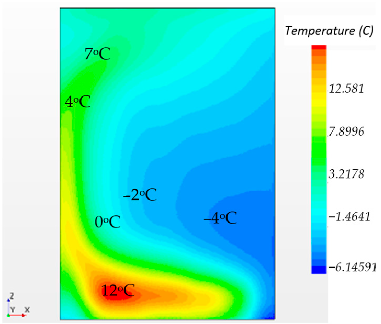
The velocity fields indicate that the heat source within the interpane space induces vortex flows of the gas, which undoubtedly affect the local and integral thermal insulation characteristics of the window unit. In CFD models V-2 and V-3, the width of the energy source coincides with the width of the window pane. Such a source, under natural convection conditions, forms two vortices along the side surfaces of the window pane. In variant V-4, the width of the energy source is smaller than the width of the window pane, and this source forms a single vortex in the interpane space. The pattern of temperature distribution on the window surface corresponds to the data presented in the work [44]. The warm vortices formed by the energy source under natural convection conditions form similar temperature field configurations, as shown in Figure 6.
The temperature fields according to variant V-4 (Figure 6) correlate with the results of thermographic imaging of the corresponding surface of the window pane, which was carried out in the climatic chamber (Figure 7).
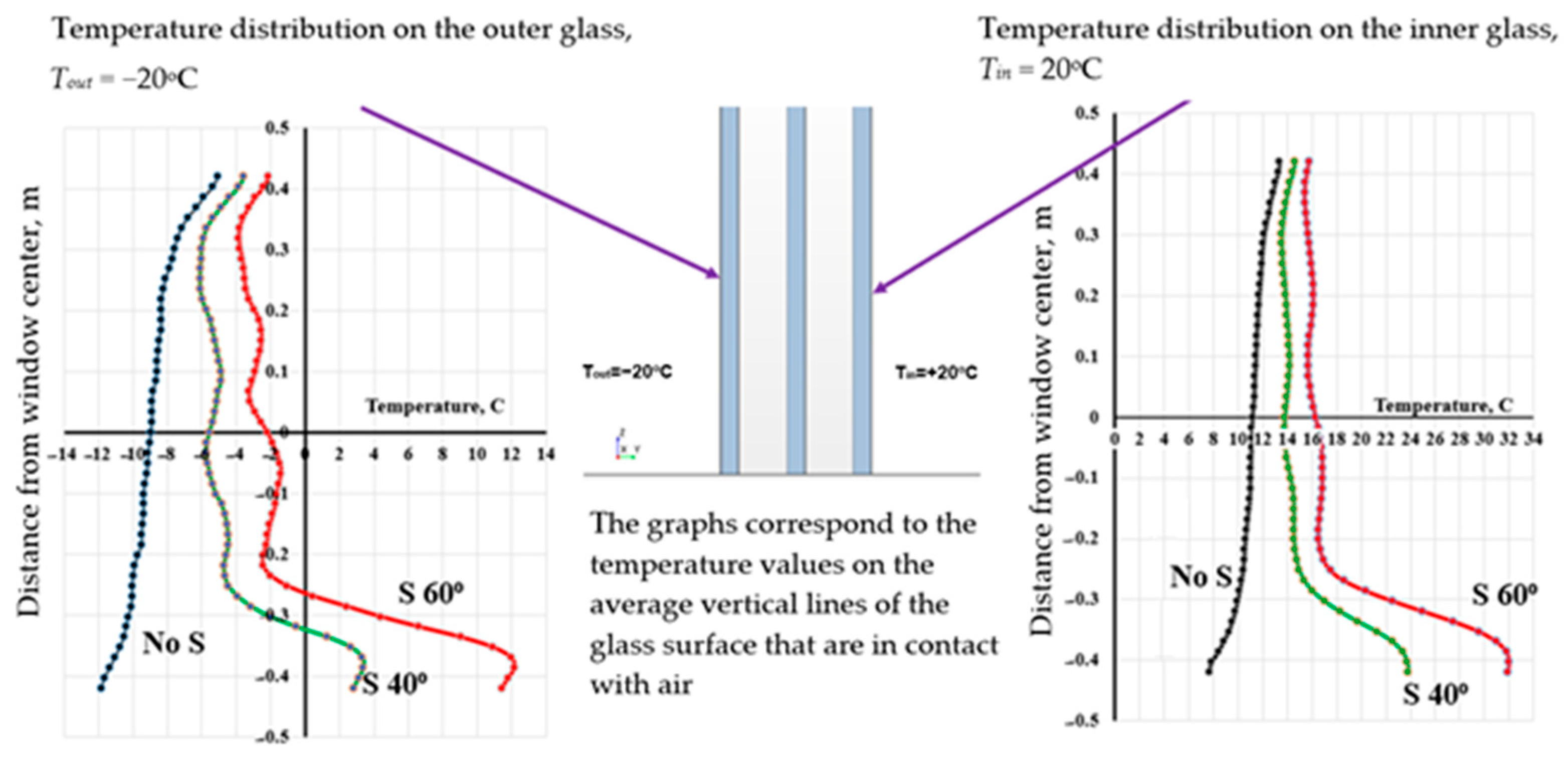
Figure 8 presents the temperature distributions on the external and internal surfaces of the window pane.
The presence of a heat source in the surfaces of the lower part of the interpane space of the window unit results in a positive temperature profile on the glass surface in contact with the cold part of the climatic chamber starting from a certain distance. This is a consequence of the reversal of the heat flux in the area of influence of the heat source (Figure 9). In the heat balance of the window, this means heat gain into the room.
The negative value of the heat flux in the right graph of Figure 9 indicates that the heat flux is leaving the warm zone of the climatic chamber. However, in the area of influence of the heat source, a reversal of the heat flux is observed. Part of the energy from the source enters the warm zone of the climatic chamber, which is at a temperature of +20 °C.
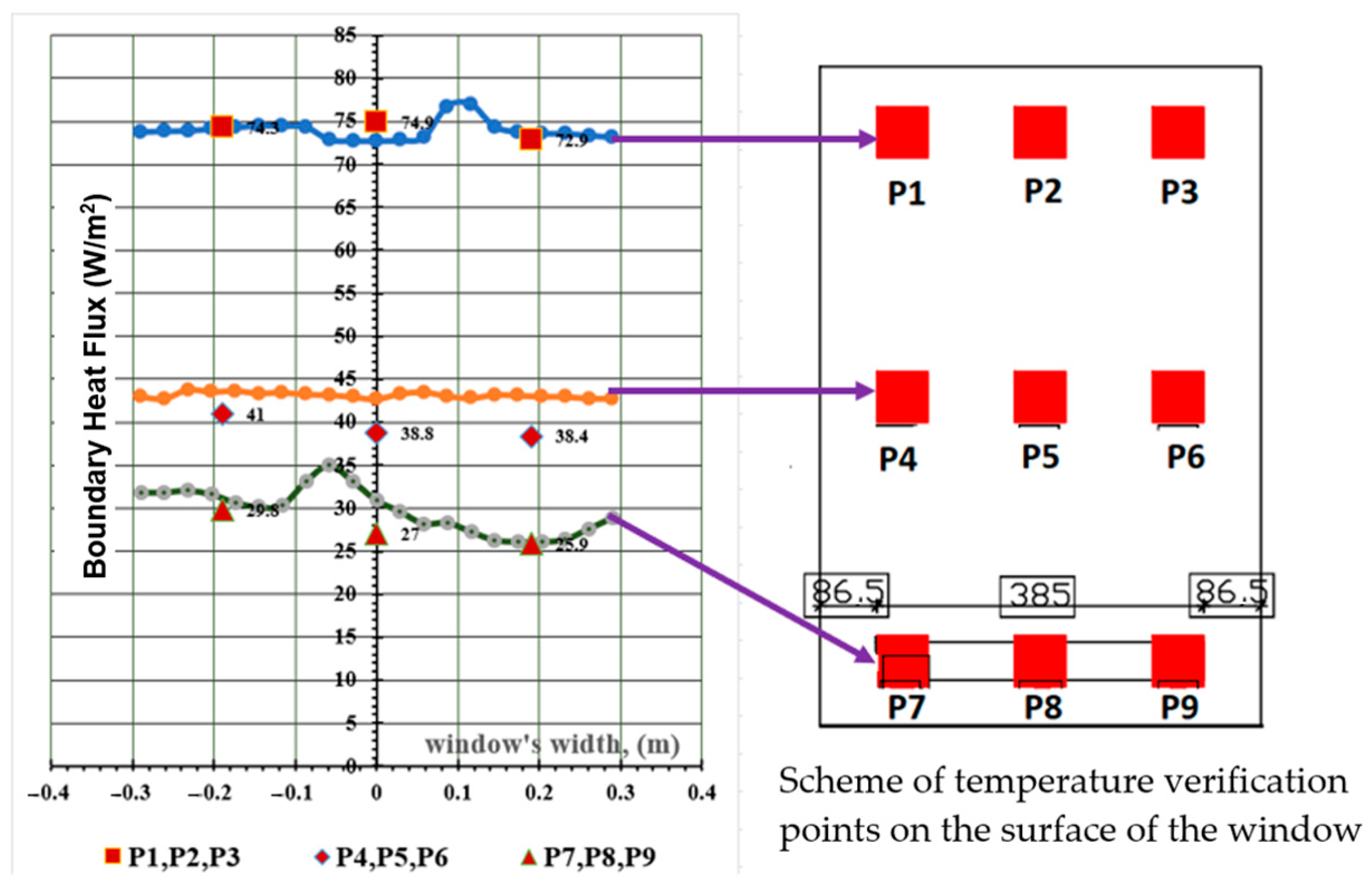
Based on the results of the heat transfer simulation through the window pane without a heat source, variant V-1, a comparison of local heat flux density values was made with experimental data obtained in the climatic chamber (Figure 10).
The right side of Figure 10 shows the location of the heat flux sensors in the window pane installed in the climatic chamber. Figure 10 shows fairly good agreement between the calculated and experimental data, with a maximum discrepancy of no more than 11–13% (sensors P5, P6, and P8). This agreement once again confirms the high efficiency of CFD modelling algorithms.
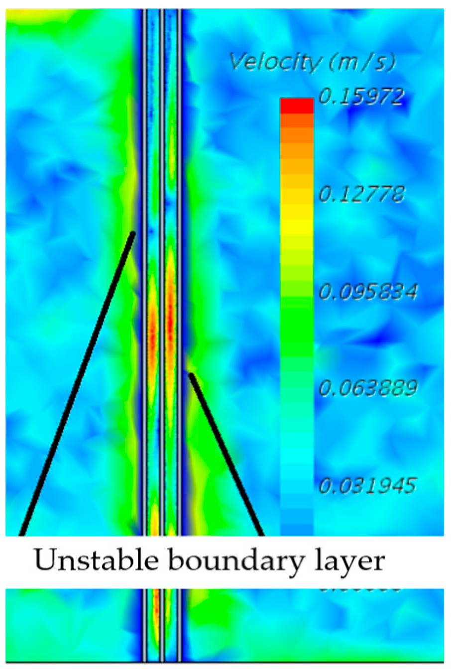
Fluctuations in the heat flux density values on the glass surfaces (Figure 9 and Figure 10) are explained by the presence of an unstable boundary layer on the glass surfaces of the window pane in contact with the air of the cold and warm zones of the climatic chamber (Figure 11). Note that the mentioned boundary layer is formed under natural convection conditions on glass surfaces in any case where there is a temperature difference between the room and the environment.
In addition to local values of the calculated parameters (Figure 8, Figure 9 and Figure 10) and values of field functions (Figure 5 and Figure 6), CFD modelling also allowed the determination of integral thermal characteristics of the system under study. Table 3 presents some thermal characteristics of the window pane depending on the power of the heat source located in the lower part of the middle glass pane on the surface closest to the warm part of the climatic chamber.
This article considers the study of only one of the options for heating window panes and their interglass filler gas, namely, electrical heating of the lower part of the middle pane of a vertical double-glazed unit (Figure 1b, Figure 3). Other heating options according to the scheme of Appendix A are planned for future publications. All results for the tested windows were compared with the results for the basic version of a window of similar geometric design and composition but without heating.

3. Discussion

This study investigated heat transfer processes in a window with an electric heater. The heater increased the temperature of the gas that circulates between the window panes. The results obtained indicate that the heat transfer intensity through the studied window was primarily regulated by convection. For such types of windows, Nusselt correlations are rarely found in the available literature, particularly for narrow open cavities with asymmetric temperature gradients on the surfaces and low Richardson numbers.
As shown in Figure 8, the gas temperature in the outer slot decreased significantly compared to the inner slot, indicating intense heat transfer to the outside. Furthermore, the heat flux through the outer glass was significantly higher than the heat transfer into the room. Considering the smaller temperature difference in the outer slot and the room, it can be concluded that the thermal resistance of such a window is higher compared to nonheated windows. However, the question of a low-potential energy source that would ensure the realisation of such effects remains unresolved. The literature offers many solutions for the use of ventilation heat, photovoltaic sources, and accumulators [51,52,53]. Smart photovoltaic windows are considered by many researchers as a solution that can increase the energy savings potential without affecting the energy efficiency of buildings [54].
The thermal characteristics of windows with an electric heater were quantitatively assessed according to the average thermal resistance (Rterm) over the window height.
The value of Rterm was influenced by several parameters (Figure 8, Figure 9 and Figure 10), characterising the dependence of the window’s thermal resistance on the heater temperature; as Ts increased, the resistance decreased. This dependence was weakly influenced by the temperature of the outdoor air. However, if Ts was close to room temperature, the outdoor air temperature did not affect the thermal resistance, which is an important finding for future research on heated windows. Therefore, to ensure the necessary values of Rterm at various outdoor air temperatures, the temperature Ts should be slightly higher than the room temperature, which in this study was 20 °C.
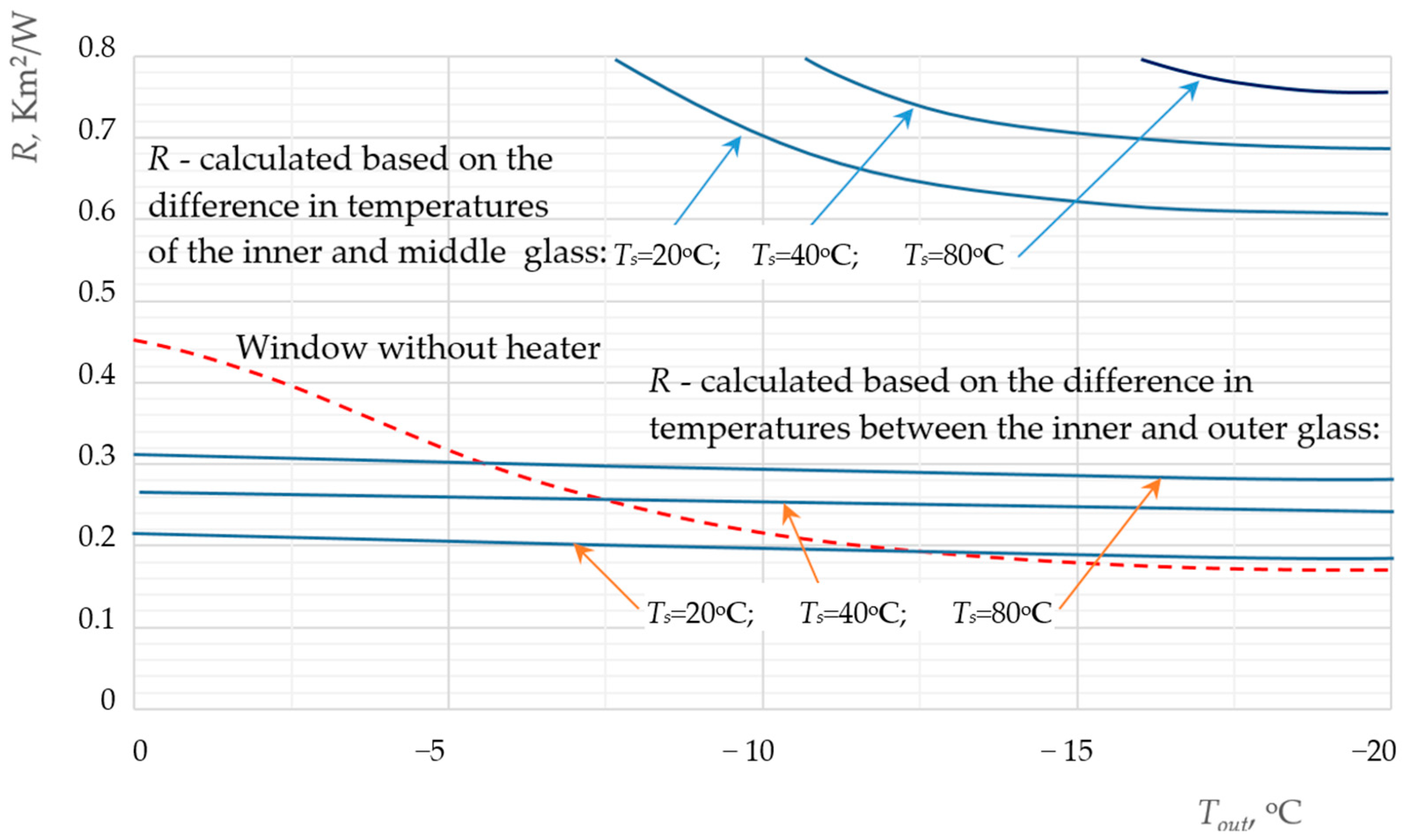
Figure 12 shows the thermal resistance of windows as a function of the outside air temperature. The graphs show that when the temperature of the heater is slightly higher than the indoor temperature, the thermal resistance of the window can be higher than that of a window without a heater. This feature is characteristic of this heater geometry.
An increase in the temperature of the heater installed in the outer gap of the window means an increase in the temperature of the outer pane and, significantly, the inner pane. Therefore, if the thermal resistance is calculated using the temperature difference between the middle and inner panes, the thermal resistance of the window becomes very high. Table 3 shows the thermal resistance of windows calculated using the temperature difference between the outer and inner panes. The traditional method of calculating the thermal resistance (R) uses exactly this temperature difference, and we see a decrease in the R value. However, the window can actually be a source of heat for the room. For example, the temperature of the outer glass at Ts = 80 °C is 1.5 °C, while the temperature of the glass without the heater is −8.9 °C, i.e., the thermal resistance of the window with the heater is actually 1.5 times higher than the resistance of the window without the heater. The increase in heat flux density at high values of Ts is associated with losses of this additional thermal energy, which is not taken into account in the traditional method of determining R. The question of the energy source for the heater remains open.
If the heat flux from the heater is directed into the room, the window can act as a heat emitter for the indoor environment. By varying the heating power and its location in operation, significant values of the thermal resistance coefficient can be achieved when the temperature of the inner glass is close to the temperature of the indoor air. An undoubted advantage of such a window design is that the local temperatures of the glass surfaces change to a lesser extent compared to traditional windows [44].
The heating element contributes to the formation of a convective flow with relatively low velocities (up to 0.5 m/s; Figure 5); therefore, for such conditions, the heat transfer coefficient can be calculated using the following formula [54].
N u = 144 R a 2 + 2.873 R a 0.5 0.5
This equation can be used to calculate the Nusselt number (Nu) in the case of vertical parallel surfaces with asymmetric temperature fields for natural convection (Ra is the Rayleigh number).
The temperature gradients along the horizontal axis in Figure 10 are insignificant; therefore, T can be assumed to be constant. To generalise the experimental results and calculations to the entire class of similar phenomena, the results are presented in a dimensionless form and in the form of a dimensionless equation.
T T s = G r · P r n y i Y 0.48 W W m a x k ,
where yi is the height of the point at which the temperature is measured (along the vertical axis of the window), y is the height of the window, W is the current heater power, and Wmax is the heater power at which the temperature Ts is reached. Exponent k is determined experimentally and depends on the heater size and its installation location.
This dependence merely illustrates the basic patterns of the heater’s influence on the energy characteristics of transparent enclosures, and, in general, the approach we applied in this work can be used to analyse the parameters of designed heated windows.

4. Conclusions

This study evaluated the thermal characteristics of a window with an electric heater and compared it with a standard double-glazed unit.
Window constructions are the weakest link in terms of specific heat loss (per unit area) to the environment from building facades. Therefore, research and innovation in the field of improving the energy efficiency of windows and reducing heat loss through them is relevant and of practical importance. This paper is dedicated to the study of increasing the overall thermal resistance of windows by implementing an additional thermal curtain through targeted heating of individual elements of the window structure, such as the inner pane. The paper presents the results of a theoretical numerical study and experimental data on measurements of aerodynamic characteristics and heat transfer through a double-glazed unit, the window profile and the part of the window opening in the wall adjacent to the window. The formula of the argon-filled double-glazed unit was 6M1-16Ar-6M1-16 Ar-6M1, the width of the aluminium window profile was 60 mm, and the indoor temperature was set at +20 °C and the ambient temperature at −20 °C. The lower part was heated across the entire width of the middle pane, using an electric current through a thin resistive plate 80 mm high, and the heating surface temperatures ranged from 40 °C to 80 °C. The window without heating was studied as a base case. As a result of the calculations and an independent experiment, the results of the thermal resistance of the whole window agreed within 12%.
Based on the data obtained, the following conclusions can be drawn:
With the appearance of a heat source in the interpane space, the thermal resistance of a double-glazed unit decreases. However, by changing the location of the heater or heaters, it is possible to ensure similar temperatures of the outer and inner glass and obtain sufficiently high values of thermal resistance. The application of such solutions would be appropriate for large facades. The heat source in this case should be a low-potential source, such as solar energy, since most of the heat supplied to the heater is lost to the outside;
The studies have established that the heat source has almost no effect on the difference between the temperatures of the inner and outer glass if the heater is installed in the outer gap of the window;
Increasing the power of the heat source leads to an increase in the heat flux to the surrounding environment, but if the temperature of the source is only slightly higher than the temperature in the room, convective heat transfer, and consequently heat losses, can be minimal;
The energy radiated from the heater is also transferred to the window construction elements and into the room, which increases the efficiency of this technical solution;
The value of Nu for parallel plates with asymmetric surface temperatures is almost twice as low as that for symmetric temperatures. This effect should be considered when designing heated windows, and at the design stage, the power, size, and position of the heater should be set at which the optimal asymmetry of temperature gradients would be maintained.
This type of window can be recommended for use during the early part of the heating season when a building is cooling down, as well as during periods of severe cold weather. At these times, water vapour can condense in the space between the panes of the double glazing and on the vertical surface of the window opening wall adjacent to the window. Calculations have shown that additional heating counteracts these undesirable effects. Such a window can also function as a supplementary (or back-up) source of heat for the building’s regular heating system.
This paper presents a pilot study aimed at evaluating the feasibility and cost-effectiveness of a method designed to minimise heat loss through transparent building envelopes before full-scale implementation.

Author Contributions

Conceptualisation, B.B. and A.P.; methodology, B.B. and A.P.; software, V.N.; validation, H.K. and A.C.; formal analysis, H.K.; investigation, M.M.; data curation, H.K.; writing—original draft preparation, B.B.; writing—review and editing, A.P.; visualisation, H.K.; supervision, M.M.; project administration, A.P.; funding acquisition, H.K. All authors have read and agreed to the published version of the manuscript.

Funding

The article was written with the Ukrainian support of the National Research Foundation within the framework of project no. 2022.01/0172: “Aerodynamics, heat transfer and innovations to improve the energy efficiency of window structures and their use for the restoration of war damaged buildings in Ukraine”.

Data Availability Statement

Dataset available on request from the authors.

Conflicts of Interest

The authors declare no conflicts of interest.

Appendix A

Figure A1. Block diagram of the research plan for windows with additional heating.
Energies 17 04491 g0a1

References

  1. Jørgensen, J.D.; Nielsen, J.H.; Giuliani, L. Thermal resistance of framed windows: Experimental study on the influence of frame shading width. Saf. Sci. 2022, 149, 105683. [Google Scholar] [CrossRef]
  2. Simões, N.; Moghaddam, S.A.; da Silva, M.G. Review of the Experimental Methods for Evaluation of Windows’ Thermal Transmittance: From Standardized Tests to New Possibilities. Buildings 2023, 13, 703. [Google Scholar] [CrossRef]
  3. Tong, S.W.; Goh, W.P.; Huang, X.; Jiang, C. A review of transparent-reflective switchable glass technologies for building facades. Renew. Sustain. Energy Rev. 2021, 152, 111615. [Google Scholar] [CrossRef]
  4. Cannavale, A.; Martellotta, F.; Fiorito, F. Novel Technologies to Enhance Energy Performance and Indoor Environmental Quality of Buildings. Buildings 2021, 11, 303. [Google Scholar] [CrossRef]
  5. Cho, K.; Cho, D.; Koo, B.; Yun, Y. Thermal Performance Analysis of Windows, Based on Argon Gas Percentages between Window Glasses. Buildings 2023, 13, 2935. [Google Scholar] [CrossRef]
  6. Cannavale, A.; Ayr, U.; Fiorito, F.; Martellotta, F. Smart Electrochromic Windows to Enhance Building Energy Efficiency and Visual Comfort. Energies 2020, 13, 1449. [Google Scholar] [CrossRef]
  7. Park, S.; Song, S.-Y. Evaluation of Alternatives for Improving the Thermal Resistance of Window Glazing Edges. Energies 2019, 12, 244. [Google Scholar] [CrossRef]
  8. Amirkhani, S.; Bahadori-Jahromi, A.; Mylona, A.; Godfrey, P.; Cook, D. Impact of Low-E Window Films on Energy Consumption and CO2 Emissions of an Existing UK Hotel Building. Sustainability 2019, 11, 4265. [Google Scholar] [CrossRef]
  9. Sorooshnia, E.; Rashidi, M.; Rahnamayiezekavat, P.; Mahmoudkelayeh, S.; Pourvaziri, M.; Kamranfar, S.; Gheibi, M.; Samali, B.; Moezzi, R. A novel approach for optimized design of low-E windows and visual comfort for residential spaces. Energy Built Environ. 2023, in press. [CrossRef]
  10. Addonizio, M.L.; Ferrara, M.; Castaldo, A.; Antonaia, A. Air-stable low-emissive AlN-Ag based coatings for energy-efficient retrofitting of existing windows. Energy Build. 2021, 250, 111259. [Google Scholar] [CrossRef]
  11. Aguilar-Santana, J.L.; Jarimi, H.; Velasco-Carrasco, M.; Riffat, S. Review on window-glazing technologies and future prospects. Int. J. Low-Carbon Technol. 2020, 15, 112–120. [Google Scholar] [CrossRef]
  12. Nur-E-Alam, M.; Vasiliev, M.; Yap, B.K.; Islam, M.A.; Fouad, Y.; Kiong, T.S. Design, fabrication, and physical properties analysis of laminated Low-E coated glass for retrofit window solutions. Energy Build. 2024, 318, 114427. [Google Scholar] [CrossRef]
  13. Chen, X.; Gu, Y. Designing surface microstructure for improving energy efficiency of SiO2 glass window by infrared emission. Energy Build. 2024, 304, 113838. [Google Scholar] [CrossRef]
  14. Marchini, F.; Chiatti, C.; Fabiani, C.; Pisello, A.L. Development of an innovative translucent–photoluminescent coating for smart windows applications: An experimental and numerical investigation. Renew. Sustain. Energy Rev. 2023, 184, 113530. [Google Scholar] [CrossRef]
  15. Liu, Y.; Zhu, W.; Sang, J.; Zhang, X.; Lee, D.W.; Seo, D.S. Flexible normally transparent smart window modulating Near-Infrared penetration under ambient conditions. Adv. Mater. Interfaces 2022, 9, 2200338. [Google Scholar] [CrossRef]
  16. Nourozi, B.; Ploskić, A.; Chen, Y.; Chiu, J.N.-W.; Wang, Q. Heat transfer model for energy-active windows—An evaluation of efficient reuse of waste heat in buildings. Renew. Energy 2020, 162, 2318–2329. [Google Scholar] [CrossRef]
  17. Misiopecki, C.; Hart, R.; Gustavsen, A.; Jelle, B.P. Operating Hardware Impact on the Heat Transfer Properties of Windows. Energies 2021, 14, 1145. [Google Scholar] [CrossRef]
  18. Onatayo, D.; Aggarwal, R.; Srinivasan, R.S.; Shah, B. A data-driven approach to thermal transmittance (U-factor) calculation of double-glazed windows with or without inert gases between the panes. Energy Build. 2024, 305, 113907. [Google Scholar] [CrossRef]
  19. Vanhoutteghem, L.; Skarning, G.C.J.; Hviid, C.A.; Svendsen, S. Impact of façade window design on energy, daylighting and thermal comfort in nearly zero-energy houses. Energy Build. 2015, 102, 149–156. [Google Scholar] [CrossRef]
  20. Mujeebu, M.A. Nano aerogel windows and glazing units for buildings’ energy efficiency. In Woodhead Publishing Series in Civil and Structural Engineering, Nanotechnology in Eco-Efficient Construction, 2nd ed.; Pacheco-Torgal, F., Diamanti, M.V., Nazari, A., Granqvist, C.G., Pruna, A., Amirkhanian, S., Eds.; Woodhead Publishing: Sawston, UK, 2019; pp. 417–439. [Google Scholar] [CrossRef]
  21. Buratti, C.; Moretti, E.; Zinzi, M. High Energy-Efficient Windows with Silica Aerogel for Building Refurbishment: Experimental Characterization and Preliminary Simulations in Different Climate Conditions. Buildings 2017, 7, 8. [Google Scholar] [CrossRef]
  22. Abraham, E.; Cherpak, V.; Senyuk, B.; Hove, J.B.T.; Lee, T.; Liu, Q.; Smalyukh, I.I. Highly transparent silanized cellulose aerogels for boosting energy efficiency of glazing in buildings. Nat. Energy 2023, 8, 381–396. [Google Scholar] [CrossRef]
  23. Field, E.; Ghosh, A. Energy assessment of advanced and switchable windows for less energy-hungry buildings in the UK. Energy 2023, 283, 128999. [Google Scholar] [CrossRef]
  24. Ghosh, A. Investigation of vacuum-integrated switchable polymer dispersed liquid crystal glazing for smart window application for less energy-hungry building. Energy 2023, 265, 126396. [Google Scholar] [CrossRef]
  25. Nundy, S.; Mesloub, A.; Alsolami, B.M.; Ghosh, A. Electrically actuated visible and near-infrared regulating switchable smart window for energy positive building: A review. J. Clean. Prod. 2021, 301, 126854. [Google Scholar] [CrossRef]
  26. Patel, M.; Seo, J.H.; Nguyen, T.T.; Kim, J. Active energy-controlling windows incorporating transparent photovoltaics and an integrated transparent heater. Cell Rep. Phys. Sci. 2021, 2, 100591. [Google Scholar] [CrossRef]
  27. Gadgil, C.; Ghosh, A.; Bhattacharjee, A.; Praveen, P.L. Electrically powered active smart windows. Next Sustain. 2024, 3, 100027. [Google Scholar] [CrossRef]
  28. Brzezicki, M. A Systematic Review of the Most Recent Concepts in Smart Windows Technologies with a Focus on Electrochromics. Sustainability 2021, 13, 9604. [Google Scholar] [CrossRef]
  29. Lee, R.; Kang, E.; Lee, H.; Yoon, J. Heat Flux and Thermal Characteristics of Electrically Heated Windows: A Case Study. Sustainability 2022, 14, 481. [Google Scholar] [CrossRef]
  30. Cakó, B.; Lovig, D.; Ózdi, A. Measuring the effects of heated windows on thermal comfort. Pollack Period. 2021, 16, 114–119. [Google Scholar] [CrossRef]
  31. Kabore, M.; Michaux, G.; Ledreau, J.; Salagnac, P.; Greffet, R. Parametric study of the thermal performance of a sin-gle-family house equipped with an airflow window integrating a heated glazing. In Proceedings of the 16th IBPSA Conference, Rome, Italy, 2–4 September 2019; pp. 2019–2025. [Google Scholar] [CrossRef]
  32. Wang, Y.; Du, D.; Yang, X.; Zhang, X.; Zhao, Y. Optoelectronic and Electrothermal Properties of Transparent Conductive Silver Nanowires Films. Nanomaterials 2019, 9, 904. [Google Scholar] [CrossRef]
  33. Li, C.; Tang, H. Phase change material window for dynamic energy flow regulation: Review. Renew. Sustain. Energy Rev. 2024, 189, 113937. [Google Scholar] [CrossRef]
  34. Jammulamadaka, H.S.; Gopalakrishnan, B.; Chaudhari, S.; Sundaramoorthy, S.; Mehta, A.R.; Mostafa, R. Evaluation of energy efficiency performance of heated windows. Energ Eng. 2022, 119, 1–16. [Google Scholar] [CrossRef]
  35. Basok, B.; Davydenko, B.; Goncharuk, S.; Pavlenko, A.; Lysenko, O.; Novikov, V. Features of heat transfer through a window with electric heating. In Proceedings of the 2022 IEEE 8th International Conference on Energy Smart Systems (ESS), Kyiv, Ukraine, 12–14 October 2022; pp. 195–198. [Google Scholar] [CrossRef]
  36. Alain, M.; Patrick, S.; Ghislain, M.; Pierre, B. Study of Thermal Comfort and Air Diffusion Induced by a Heated Airflow Window. Available online: https://ssrn.com/abstract=4578448 (accessed on 1 December 2022).
  37. Michaux, G.; Greffet, R.; Salagnac, P.; Ridoret, J.-B. Modelling of an airflow window and numerical investigation of its thermal performances by comparison to conventional double and triple-glazed windows. Appl. Energy 2019, 242, 27–45. [Google Scholar] [CrossRef]
  38. ISO 15099; Thermal Performance of Windows, Doors and Shading Devices—Detailed Calculations. International Organization for Standardization: Geneva, Switzerland, 2003.
  39. Wang, Z.; Liang, J.; Lei, D.; Jiang, C.; Yang, Z.; Yang, G.; Zhang, D.; Zhang, L.; Zhang, C.; Bai, Y. Temperature-adaptive smart windows with passive transmittance and radiative cooling regulation. Appl. Energy 2024, 369, 123619. [Google Scholar] [CrossRef]
  40. Zhou, Z.; Fang, Y.; Wang, X.; Yang, E.; Liu, R.; Zhou, X.; Huang, Z.; Yin, H.; Zhou, J.; Hu, B. Synergistic modulation of solar and thermal radiation in dynamic energy-efficient windows. Nano Energy 2022, 93, 106865. [Google Scholar] [CrossRef]
  41. Zhang, R.; Li, R.; Xu, P.; Zhong, W.; Zhang, Y.; Luo, Z.; Xiang, B. Thermochromic smart window utilizing passive radiative cooling for Self-Adaptive thermoregulation. Chem. Eng. J. 2023, 471, 144527. [Google Scholar] [CrossRef]
  42. Wu, S.; Sun, H.; Duan, M.; Mao, H.; Wu, Y.; Zhao, H.; Lin, B. Applications of thermochromic and electrochromic smart windows: Materials to buildings. Cell Rep. Phys. Sci. 2023, 4, 101370. [Google Scholar] [CrossRef]
  43. Luo, L.; Liang, Y.; Feng, Y.; Mo, D.; Zhang, Y.; Chen, J. Recent Progress on Preparation Strategies of Liquid Crystal Smart Windows. Crystals 2022, 12, 1426. [Google Scholar] [CrossRef]
  44. Pavlenko, A.M.; Sadko, K. Evaluation of Numerical Methods for Predicting the Energy Performance of Windows. Energies 2023, 16, 1425. [Google Scholar] [CrossRef]
  45. Basok, B.; Davydenko, B.; Novikov, V.; Pavlenko, A.M.; Novitska, M.; Sadko, K.; Goncharuk, S. Evaluation of Heat Transfer Rates through Transparent Dividing Structures. Energies 2022, 15, 4910. [Google Scholar] [CrossRef]
  46. Alosaimi, F.; Almutairi, A. Heat Transfer Analysis of Double and Triple Glazed Glass Windows. In Proceedings of the 2nd International Civil Engineering and Architecture Conference, Singapore, 11–14 March 2022; Casini, M., Ed.; CEAC 2022. Lecture Notes in Civil Engineering. Springer: Singapore, 2023; Volume 279. [Google Scholar] [CrossRef]
  47. Koo, S.Y.; Park, S.; Song, J.-H.; Song, S.-Y. Effect of Surface Thermal Resistance on the Simulation Accuracy of the Condensation Risk Assessment for a High-Performance Window. Energies 2018, 11, 382. [Google Scholar] [CrossRef]
  48. Pavlenko, A.; Usenko, B.; Koshlak, A. Thermal conductivity of the gas in small space. Metall. Min. Ind. 2014, 6, 20–24. [Google Scholar]
  49. Lahmar, I.; Cannavale, A.; Martellotta, F.; Zemmouri, N. The Impact of Building Orientation and Window-to-Wall Ratio on the Performance of Electrochromic Glazing in Hot Arid Climates: A Parametric Assessment. Buildings 2022, 12, 724. [Google Scholar] [CrossRef]
  50. Elmalky, A.M.; Araji, M.T. Computational fluid dynamics using finite volume method: A numerical model for Double Skin Façades with renewable energy source in cold climates. J. Build. Eng. 2022, 60, 105231. [Google Scholar] [CrossRef]
  51. Bonomo, P.; Frontini, F. Building Integrated Photovoltaics (BIPV): Analysis of the Technological Transfer Process and Innovation Dynamics in the Swiss Building Sector. Buildings 2024, 14, 1510. [Google Scholar] [CrossRef]
  52. Basok, B.; Davydenko, B.; Pavlenko, A.M. Numerical Network Modeling of Heat and Moisture Transfer through Capillary-Porous Building Materials. Materials 2021, 14, 1819. [Google Scholar] [CrossRef] [PubMed]
  53. Meng, Y.; Tan, Y.; Li, X.; Cai, Y.; Peng, J.; Long, Y. Building-integrated photovoltaic smart window with energy generation and conservation. Appl. Energy 2022, 324, 119676. [Google Scholar] [CrossRef]
  54. Shi, S.; Zhu, N. Challenges and Optimization of Building-Integrated Photovoltaics (BIPV) Windows: A Review. Sustainability 2023, 15, 15876. [Google Scholar] [CrossRef]
Figure 1. Scheme of the measuring stand: (a) appearance of the climate chamber; (b) installation diagram of temperature and heat flow sensors; (c) temperature field on the inside of the window; (d) temperatures on the outside of the window; XM1-9—points at which the calculation data were verified. Example of thermograms for 20 °C internal temperature and 0 °C and −20 °C external temperatures, with a heater temperature of 40 °C.
Energies 17 04491 g001aEnergies 17 04491 g001b
Figure 2. Geometric model: 1—two-chamber window pane (6M1-16-6M1-16-6M1) with dimensions of 0.840 × 0.580 m; 2—cold part of the climate chamber, air Tout = –20 °C; 3—warm part of the climate chamber, air Tin = 20 °C; 4—heat source, 0.08 × 0.580 m.
Energies 17 04491 g002
Figure 3. Schematic diagram of the energy-source arrangement in the window.
Energies 17 04491 g003
Figure 4. The boundary conditions for a CFD model.
Energies 17 04491 g004
Figure 5. Argon velocity fields in the interpane space of a window pane: (a) gas flow velocity in the outer gap of the window; (b) vector graph V-2 (Figure 5a).
Energies 17 04491 g005
Figure 6. Temperature fields on the glass surface in contact with air at a temperature of −20 °C.
Energies 17 04491 g006
Figure 7. Comparison of CFD simulation results with experimental data obtained in the climatic chamber (Th = 60 °C; Figure 1).
Energies 17 04491 g007
Figure 8. Temperature distribution across the external surfaces of a window pane.
Energies 17 04491 g008
Figure 9. Heat flux density distributions on the surfaces of the window pane.
Energies 17 04491 g009
Figure 10. Comparison of experimental results with local heat flux density values on the glass surface facing the cold zone of the climatic chamber.
Energies 17 04491 g010
Figure 11. Velocity field. Vertical cross section of the model with a heat source at a temperature of 60 °C.
Energies 17 04491 g011
Figure 12. Dependence of the thermal resistance of a window on external air temperature.
Energies 17 04491 g012
Table 1. The boundary conditions.
Boundary Surface AreaBoundary Conditions
Thermal insulation conditions are set on the end surfaces of the double-glazing unit (Figure 4)q = 0
Side surfaces that restrict the air in the model, both from the warm part of the chamber and the cold part (Figure 4)Symmetry conditions
On the “solid–gas” and “solid–solid” surfacesConditions of conjugation
The end surfaces of the model’s air areas:
On the cold side of the chamber–20 °C
From the side of the warm part of the chamber20 °C
Table 2. Modelling options.
Variant NumberType of Window
Variant 1 (V-1)Two-chamber window pane without a heat source
Variant 2 (V-2)Two-chamber window pane, heat source at 40 °C
Variant 3 (V-3)Two-chamber window pane, heat source at 60 °C
Variant 4 (V-4)Two-chamber window pane, heat source at 80 °C
Table 3. Calculated data.
SourceV-1,
No Source
V-2,
Ts = 40 °C
V-3,
Ts = 60 °C
V-4,
Ts = 80 °C
Average temperature of the glass surface in contact with the warm air inside the window, Tin (°C)11.116.119.120.9
Average temperature of the glass surface in contact with the cold air in the climatic chamber, Tout (°C)−8.9−3.4−0.071.5
Temperature difference, ΔT = TinTout2019.519.1719.4
Average heat flux density on the glass surface in contact with the cold air in the climatic chamber, Qout (W/m2)43.5688499.4
Thermal resistance, Rterm = ΔT/Qout, (m2 K)/W0.4600.2870.2280.195
Disclaimer/Publisher’s Note: The statements, opinions and data contained in all publications are solely those of the individual author(s) and contributor(s) and not of MDPI and/or the editor(s). MDPI and/or the editor(s) disclaim responsibility for any injury to people or property resulting from any ideas, methods, instructions or products referred to in the content.