
Efficiency Enhancement in Photovoltaic–Thermoelectric Hybrid Systems through Cooling Strategies


1
Department of Nanoscience and Nanoengineering, Institute of Natural Sciences, Sakarya University, Sakarya 54187, Turkey
2
Turkish Standards Institution, İstanbul 34953, Turkey
3
Department of Computer Technologies, Vocational School of Karasu, University of Applied Sciences, Sakarya 54500, Turkey
4
Power Electronics Technologies Research and Application Center, University of Applied Sciences, Sakarya 54500, Turkey
5
Instituto de Engenharia de Sistemas e Computadores—Microsistemas e Nanotecnologias (INESC MN), 1000-029 Lisbon, Portugal
6
Department of Fundamental Sciences and Engineering, Sivas University of Science and Technology, Sivas 58000, Turkey
*
Author to whom correspondence should be addressed.
Energies 2024, 17(2), 430; https://doi.org/10.3390/en17020430
Submission received: 27 November 2023
/
Revised: 8 January 2024
/
Accepted: 11 January 2024
/
Published: 16 January 2024
(This article belongs to the Topic Advances in Renewable Energy Technologies and Systems Solutions)
Abstract
:The integration of photovoltaic (PV) and thermoelectric (TE) modules in PV-TE systems has shown potential for expanding the utilization of the solar spectrum, enhancing the total power output, and reducing the space that is required for PV power plants. This paper discusses the characteristics of a practical PV-TE system model. Typically, to boost the power output of the TE component, a significant temperature difference is induced across the thermoelectric generator (TEG) module using various heat removal methods. These cooling techniques not only enhance the TEG module’s efficiency but may also improve the performance of the PV component. In this study, we evaluate the efficiencies of PV-TE systems that are equipped with polycrystalline silicon solar cells and seven distinct TEGs under four different conditions. Initially, the PV-TE hybrid systems are tested without a cooling mechanism at an ambient temperature of 25 °C (Standard Test Conditions EN/IEC 61215). Subsequently, we examine the systems with a passive cooling approach, employing aluminum heat sinks to facilitate improved heat dissipation. Further tests involve an active cooling system using water and then nanofluid as coolants. The results from these assessments aim to establish a benchmark for enhancing the efficiency of future PV-TE systems.
1. Introduction
The post-industrial revolution era witnessed rapid development and a surge in comfort demands, driving an increased energy consumption and, consequently, heightened CO2 and greenhouse gas emissions. A total of 80% of the emission of greenhouse gases, predominantly stemming from fossil fuel usage, pose a significant contemporary environmental challenge. This trajectory is projected to elevate global temperatures by 0.6 to 2.5 °C in the coming 50 years, with dire implications for our environment, chiefly as the prime drivers of global warming and ensuing climate change. Researchers working on solar cell technologies have focused on new solar cell technologies. Their efforts have centered on reducing material usage and costs, adopting innovative hybrid approaches, and augmenting the production capacity. In recent decades, photovoltaic research has demonstrated remarkable progress in enhancing efficiency, evolving from around 13% in 1977 (for single-junction, non-concentrated single-crystalline solar cells) to the current record efficiency of 47.6% in concentrated, four-junction solar cells [1]. Concurrently, the cost of solar energy has plummeted from USD 77 per watt in 1977 to a mere USD 0.35 per watt in 2023 [2]. Although photovoltaic technology is commercially used in lots of countries as the major renewable energy source, the efficiency of the PV plants is still quite low, because more than 80% of the potential energy coming from the sun to the PV power plant area is wasted. On the other hand, the cost of pure PV solar modules is decreasing due to new research on increasing the efficiency of solar cells [3,4,5].
Photovoltaic researchers have pursued three primary strategies: developing new materials, enhancing sunlight utilization for energy recovery, and employing photovoltaic–thermoelectric (PV-TE) systems to convert heat into electricity. The rising global population constrains the available land for future photovoltaic power plants, underscoring the need for improved solar cell efficiency and photovoltaic system effectiveness, with PV-TE emerging as a noteworthy solution. Especially, in recent decades, hybrid power generation systems like photovoltaic hybrid systems such as PV-TE have gained enormous awareness [6,7,8].
Using thermoelectric generators (TEGs) in PV-TE systems offers a promising way to harvest thermal energy and boost power output. The use of TE modules increases the power output, and previous laboratory test results showed an increase of up to 39% of PV-TE compared with the PV of a PV-TE without the TE part [9,10,11,12]. TE modules directly convert heat energy into electricity, based on the temperature differences between the plains of the module. Unlike photovoltaic cells that rely on high-energy photons, TEGs can convert heat from lower-energy photons into electricity without increasing the cell temperature of the PV part. One of the advantages of the PV-TE system is the demolishing of the adverse influencing factor of the heat for the PV solar cell, as this heat is converted to electrical energy by the TE part of the PV-TE system [13,14]. A PV-TE hybrid system is a useful technology to use the solar irradiation in full spectra and obtain a higher amount of energy [15,16]. PV-TE hybrid systems are proposed, tested, and fabricated in order to increase the total efficiency of solar energy [17,18,19,20]. Especially in recent years, PV-TE hybrid systems have gained more attention [21,22,23,24,25,26,27,28,29,30].
PV-TE hybrid systems are particularly effective in regions with high solar irradiation [31,32,33,34,35], but even in areas with lower solar radiation, the TE component can generate power when the PV-TE system has a cooling mechanism, making them commercially viable and profitable [36,37,38,39,40].
TE modules offer solid-state reliability, although their cost does not always align with efficiency. In fact, a less expensive TE module can outperform a pricier one. Their cost depends on materials, working temperatures, and size. As the TE module converts this heat into electricity, the PV component temperature decreases, boosting PV efficiency. An active cooling system in PV-TE hybrids keeps the TE module’s cold side consistently cool, increasing energy efficiency and mitigating environmental impacts. Traditional PV systems raise the backside temperature of PV modules to 25–30 °C above the ambient temperature, but with a TE module beneath the PV module, this heat is directly converted into electrical energy, eliminating this environmental concern [41].
In this study, we evaluated the performance of PV-TE systems, specifically those using polycrystalline silicon solar cells, coupled with seven different types of TEGs. Our assessment was carried out under four distinct conditions. Initially, we analyzed the PV-TE hybrid systems’ efficiency at an ambient temperature of 25 °C without any cooling mechanism. We then progressed to incorporate a passive cooling system, utilizing aluminum heat sinks designed to enhance heat dissipation significantly. Further evaluations included an active cooling system, first using water and then nanofluid as coolants. The insights derived from these varied tests have laid the groundwork for advancing the efficiency of PV-TE systems.
2. Materials and Methods
In this study, we conducted a detailed analysis of the performance of photovoltaic–thermal (PV-TE) systems that integrate poly-crystalline silicon solar cells with seven distinct thermoelectric generators (TEGs) under various temperature scenarios. These systems were examined in four separate configurations: without a cooling system, with passive cooling, and with active cooling utilizing either distilled water or a nanofluid as the coolant medium. For clarity and ease of reference in the resultant graphs and tables, the TEGs are designated numerically (e.g., TEG1, TEG2). Additionally, Table 1 presents a thorough summary, listing the identification number, manufacturer details, and model specifications, thermoelectric materials used, the thickness of the thermoelectric generator (TEG is the thicknesses of the thermoelectric generator (TEG), surface, P-N junctions, and the plate materials for each TEG). The dimensions of each TEG are 40 × 40 mm.
The PV-TE system schematic in Figure 1 depicts the PV module in the upper section and the TE module in the lower section. Incident sunlight on the PV module generates electron–hole pairs if the photon energy exceeds the semiconductor’s bandgap energy (Egap), resulting in electrical energy. However, lower-energy photons increase the module’s temperature, raising its resistance due to the temperature–resistance relationship. This diminishes the PV module’s efficiency. The TE module is directly affixed to the PV module’s rear surface, allowing the thermal energy produced in the PV module to transfer to the TE module. TEGs are designed to generate an electric potential by utilizing the Seebeck Effect, which occurs at the junction of two dissimilar conductors at different temperatures. Through this phenomenon, TEGs are capable of converting thermal energy to electrical energy. The pursuit of increased efficiency in TE modules through advanced and diverse strategies is imperative for optimizing the overall functionality and performance of PV-TE hybrid systems. Enhancements in this domain promise to yield substantial improvements in energy conversion efficiency, thereby elevating the efficacy and potential application of these hybrid systems in various sectors [42,43,44,45].
The electrical illustration of the PV and TE parts of the hybrid system is depicted as a four-wire system. This allows for the independent measurement and evaluation of energy from the PV and TE parts, as well as a more accurate assessment of their respective efficiencies. The PV and TE parts each have their own distinct electrical output systems.
The TE modules have two plate sides. In PV-TE systems, the side which is connected to the PV module is the hot side, and the other side is the cold side. In the simplest PV-TE systems, the hot side receives heat from the PV part while the cold side, not connected to any equipment, only dissipates heat into the air. Under normal conditions, the temperature difference between the rear side of a working PV module and the ambient air is approximately 25–30 °C. If the ambient temperature is relatively warm, the cold side of the TE module heats up quickly, potentially equalizing with the hot side’s temperature. In the assessment of the PV-TE hybrid system, precise temperature control plays a pivotal role. As previously outlined, the ambient temperature (Ta) is set at a constant 25. However, our primary focus in this research is on regulating the hot side’s temperature (Th) of the TEG using constantly calibrated test equipment from our laboratory. For this study, we experimented with TEGs at Th values ranging from 30 °C to 70 °C. But for commercialization, the values of 50 °C and 70 °C are important. This is because the TE part utilizes the temperature difference between the cold side and the hot side, which is affixed to the back sheet of the PV part, as its energy source. The temperature of the hot side of the TE is proportional to the temperature of the back sheet of the PV module. The backside of the PV part is normally 25–30 °C higher than the Ta. This means that Th is nearly 50 °C when the Ta is 25 °C. For the tests without a cooling system and with a passive cooling system, the initial value of the temperature of the cold side of the TEG (Tc) was equal to the Ta. But for the active cooling systems, a liquid with 10 °C temperature was provided to the test system. Tests were conducted in the accredited Photovoltaics and Calibration Laboratories at the Turkish Standards Institution, compliant with EN ISO/IEC 17025 requirements [46]. The equipment used was meticulously calibrated. The tests followed the EN/IEC 61215 standards and were conducted at an ambient temperature of 25 °C [47]. The temperature on the TE component’s hot side was varied from 30 °C to 70 °C in 5 °C increments for measurements.
3. Results and Discussion
The outcomes of our tests on the TE modules that were tested without a cooling system closely aligned with our initial expectations. In Figure 2a, we present the results of the voltage-time tests performed on seven TEGs, all operating at a constant hot side (Th) temperature of 50 °C. A noteworthy observation from our findings is the very short time that it takes for both sides of the TEGs to reach temperature equalization. Specifically, we observed that TEG2 and TEG3, featuring ceramic plates, exhibited superior performance when subjected to a hot-side temperature (Th) of 50 °C. It is worth emphasizing that this temperature closely approximates the back sheet temperature of the PV module under Standard Test Conditions (STC). Conversely, the two TEGs that were equipped with graphite plates demonstrated relatively lower output performance when compared to their ceramic counterparts. These observations provide a valuable understanding of the distinctive thermal characteristics that are associated with various TEG configurations and their potential implications for the overall system performance.
Expanding upon our observations, Figure 2b illustrates that even under a Th of 70 °C, the TEGs with ceramic plates maintain higher output levels compared to the TEGs with graphite sheets. Notably, TEG2 and TEG3 consistently deliver superior outputs, mirroring the results observed at 50 °C Th. This reaffirms that TEGs with graphite sheets exhibit lower output levels, underscoring the performance differences between TEGs with ceramic and graphite plates, which remain consistent even at higher operating temperatures of 70 °C Th. In the context of advancing PV-TE efficiency, the next step entails the incorporation of an aluminum heat sink beneath the cold side of the TE module, as visually depicted in Figure 3. This approach extends the duration of the temperature equalization across both sides of the TE module, serving as a critical enhancement in our research.
To conduct this investigation, we opted for an aluminum heat sink with dimensions that were identical to the TE modules in use. This approach effectively transforms the PV-TE system into one with a passive cooling system. The results obtained through this methodology are designated by the label “PC” (passive cooling) in our graphical representations. This strategic initiative marks a critical advancement in our research. It elucidates the prospective benefits derived from incorporating passive cooling mechanisms into the PV-TE system, aimed at enhancing the overall performance and efficiency The experiments for the TE component of the PV-TE system were conducted at the Calibration Laboratory of the Turkish Standards Institution. To characterize the PV component of the PV-TE hybrid system, we used a heating plate from the ACSII-2000 Temperature Calibration System, provided by Anritsu Meter Co., LTD, Tokyo, Japan. The heating plate of this unit consistently maintains the required temperature, ensuring that the hot side of the TE component remains at the necessary temperature throughout testing. Figure 4 illustrates the schematic of the testing method for the TE component. For all test types in this research, the tests are conducted at temperatures ranging from 30 °C to 70 °C Th, with 5 °C increments.
To enhance the efficiency of the PV-TE system, we implemented an active cooling system as a key component of our research methodology. This system employs a liquid tank containing a stable-temperature liquid refrigerant. The temperature of this liquid is meticulously maintained at a constant level throughout the experimental process. The active cooling system comprises several integral components, including a liquid pump, flexible piping, and an aluminum water cooling block heat sink, all of which share identical plate dimensions with the TE modules that are employed. These elements collectively facilitate the circulation of the cold liquid, which plays a pivotal role in actively cooling the TE portion of the system, as illustrated in detail in Figure 5.
This strategic integration of an active cooling mechanism represents a significant advancement in our research efforts, with the aim of optimizing the overall performance and efficiency of the PV-TE system. By precisely controlling the temperature of the circulating liquid, we can explore the potential benefits and intricacies of active cooling, thus contributing valuable insights to the field of thermoelectric power generation. In this phase of our experimental endeavors, we used distilled water as the coolant for the active cooling experiments. Cold water with a temperature of 10 °C is circulated in the active cooling system. With this system, the temperature difference between the cold and the hot side of the TE part is increased, and the TE part of the PV-TE system achieved higher efficiencies in the experiments. The results obtained through this active cooling approach, where distilled water was utilized as the coolant, are distinctly labeled with the designation “AC” (active cooling) in our graphical representations. This approach has proven instrumental in achieving higher efficiencies within the PV-TE system, a promising development that stands as a testament to the potential advantages of actively controlling the temperature dynamics in thermoelectric power generation.
The figures presented in Figure 6a,b highlight discernible disparities in both the current and voltage outputs of TEG3 under three distinct operating conditions. These findings underscore a notable trend: the implementation of an active cooling system consistently results in elevated voltage and current outputs from the TEG. Additionally, a significant benefit of the active cooling system is the rapid achievement of stable and consistent values for both the current and voltage. This attribute is particularly valuable, as it significantly reduces the time required to achieve steady-state performance, thus enhancing the reliability and efficiency of TEG3. These observations substantiate the advantages of incorporating an active cooling system within the PV-TE hybrid system, demonstrating its potential to improve output characteristics and overall system stability.
The analysis of the current and voltage outputs from TEG4 under three distinct conditions, as illustrated in Figure 7a,b, underscores the favorable impact of employing an active cooling system. It is evident that incorporating this system results in significantly higher voltage and current outputs from the TEGs. This outcome mirrors the trends observed in the case of TEG3, reaffirming the active cooling system’s capability to swiftly establish and maintain stable current and voltage values, a critical factor that could pave the way for the commercialization of PV-TE hybrid systems.
Moreover, a noteworthy observation from the results of TEG4 is its superior performance when compared to TEG3, both equipped with cooling systems. This variation in performance can be attributed to the inherent semiconductor characteristics of TEGs. These devices exhibit differing efficiencies at varying temperatures and temperature differences of their cold and hot sides.
Subsequently, we explored the utilization of nanofluids as a coolant to further augment the temperature differential across the TE module, thereby enhancing the efficiency of the TE modules. The results obtained through this method are explicitly marked with the designation “nAC” (nanofluid active cooling) in our graphical representations. In pursuit of higher voltage, current, and power outputs, we utilized a Gamma Aluminium Oxide (Alumina, Al2O3) nanofluid, specifically in the gamma phase, with an average particle size ranging from 20 to 50 nm as the coolant. This choice is supported by previous research findings and theoretical considerations, which collectively indicate that an active cooling system employing nanofluids yields superior electrical outputs compared to one utilizing distilled water as the coolant [48,49]. These findings further underscore the potential of advanced cooling techniques to optimize the performance of PV-TE systems.
Figure 8a,b present the power outputs of TEG3 and TEG4 using four different methods: without a cooling system, with passive cooling, with active cooling, and with an active cooling system using nanofluid, all under 50 °C Th in mW. The results indicate that both the active cooling system and the active cooling system with nanofluids achieve significantly higher outputs compared to the passive cooling system. The results show that TEG4 has a still higher electrical output than TEG3. The experimental results from this research clearly demonstrate the performance increase in PV-TE systems compared to pure PV parts. Table 2 displays the power outputs of pure PV, PV-TE with TEG3 without cooling, PV-TE with TEG3 with passive cooling, and PV-TE with TEG3 with active cooling using distilled water and nanofluids. We can easily see that the active cooling is a very successful way to obtain higher outputs from PV-TE systems. Under stable conditions, using TEG3 with an active cooling system result in a 3.59% power increase with distilled water and a 3.69% power increase with the nanofluid.
According to our experimental test results, TEG4 has the highest electrical outputs, both with passive cooling and active cooling, of all the TEGs that we have used for this research. Table 3 gives us information about the power outputs of pure PV, PV-TE with TEG4 without cooling, PV-TE with TEG4 with passive cooling, and PV-TE with TEG4 with active cooling by using distilled water and a nanofluid.
4. Conclusions
In summary, our extensive research delves into the optimization of photovoltaic–thermoelectric (PV-TE) systems, focusing on performance enhancements that are achieved through advanced cooling strategies and the material composition in thermoelectric generators (TEGs). We have identified that ceramic-plate TEGs significantly outperform their graphite counterparts, particularly at higher operating temperatures, due to the rapid temperature equalization. This superiority is further enhanced by integrating both passive and active cooling systems, with nanofluids showing a substantial increase in the efficiency and power output of TEGs. These results highlight the potential of nanofluids in future PV-TE applications, promising avenues for enhancing system efficiency. Our scientific investigation also emphasizes the critical role of cooling systems in PV-TE hybrid systems. We found that TEGs with ceramic plates demonstrate more efficient heat transfer and energy output than those with graphite, mainly due to the distinct properties of micro-materials and nanomaterials. Moreover, the incorporation of an aluminum heat sink and Gamma Aluminum Oxide nanofluid in active cooling systems marked a significant advancement in the system design and performance. Cost-efficiency is also a paramount consideration for the commercial viability of these systems. While TEG4 showed the highest power output, its higher cost may limit its commercial use. Conversely, TEG3, with nearly the highest voltage output and a lower cost, emerges as a more viable option. Our findings suggest that when selecting TEG materials, favoring ceramic plates over graphite is pivotal due to their higher efficiency and potential cost-effectiveness. Furthermore, our study explored the influence of the p-n junction size in TEGs, revealing that a thinner junction, as seen in TEG4, enhances heat transfer efficiency. This indicates that optimizing the p-n junction size is crucial for maximizing the cooling capacity of TEGs, with significant design and performance implications. Integrating PV-TE systems into existing PV power plants represents a promising strategy to enhance the overall efficiency. By attaching TEGs under each solar cell and incorporating cooling block heat sinks with an active system, we can potentially transform current energy infrastructures with minimal disruption. These findings not only contribute to the scientific understanding of PV-TE systems but also provide practical guidance for future research and commercial applications. Further investigation is necessary to explore the long-term performance and scalability of these systems, particularly in real-world commercial settings. This future research will be crucial in realizing the full potential of PV-TE systems for a sustainable and efficient energy future.
Author Contributions
Conceptualization, S.B. and M.E.; methodology S.B., E.B. and M.E.; software, S.B. and E.B.; validation, S.B., E.B. and M.E.; formal analysis, S.B. and M.E.; investigation, S.B. and M.E. resources, M.E.; data curation, S.B. and M.E.; writing—original draft preparation, S.B. and E.B.; writing—review and editing, S.B. and M.E. visualization, S.B., E.B. and M.E.; project administration, M.E.; funding acquisition, M.E. All authors have read and agreed to the published version of the manuscript.
Funding
This research received no external funding.
Data Availability Statement
The data presented in this study are available on request from the corresponding author.
Conflicts of Interest
The authors declare no conflicts of interest.
Abbreviations
| PV | Photovoltaic |
| TE | Thermoelectric |
| TEG | Thermoelectric Generator |
| PV-TE | Photovoltaic–Thermoelectric |
| STC | Standard Test Conditions |
| IEC | International Electrotechnical Commission |
| EN | European Norms |
| CO2 | Carbon Dioxide |
| °C | Celsius |
| RPV | Photovoltaic Resistance |
| Th | Hot-Side Temperature |
| TC | Cold-Side Temperature |
| RTEG | Resistance of TEG |
| Ta | Ambient Temperature |
| STC | Standard Test Conditions |
| PC | Passive Cooling |
| P | Positive Material |
| N | Negative Material |
| AC | Active Cooling |
| nAC | Nanofluid Active Cooling |
| Al2O3 | Aluminum Oxide |
| Egap | Bandgap Energy |
| ISO | International Organization for Standardization |
References
- National Renewable Energy Laboratory. Available online: http://www.nrel.gov/ncpv/images/efficiency_chart.png (accessed on 13 September 2023).
- Solar Photovoltaic Panel Prices vs. Cumulative Capacity. Available online: https://ourworldindata.org/ (accessed on 29 September 2023).
- Madeti, S.R.; Singh, S.N. Monitoring system for photovoltaic plants: A review. Renew. Sustain. Energy Rev. 2017, 67, 1180–1207. [Google Scholar] [CrossRef]
- Bilen, K.; Erdoğan, İ. Effects of cooling on performance of photovoltaic/thermal (PV/T) solar panels: A comprehensive review. Sol. Energy 2023, 262, 111829. [Google Scholar] [CrossRef]
- Dada, M.; Popoola, P. Recent advances in solar photovoltaic materials and systems for energy storage applications: A review. Beni-Suef Univ. J. Basic Appl. Sci. 2023, 12, 66. [Google Scholar] [CrossRef]
- Lu, Z.; Huang, Y.; Zhao, Y. Performance investigation of a concentrated photovoltaic-thermoelectric hybrid system for electricity and cooling production. Appl. Therm. Eng. 2023, 231, 120916. [Google Scholar] [CrossRef]
- Zhao, Q.; Zhang, H.; Hu, Z.; Hou, S. Achieving a broad-spectrum photovoltaic system by hybridizing a two-stage thermoelectric generator. Energy Convers. Manag. 2020, 211, 112778. [Google Scholar] [CrossRef]
- Cristaldi, L.; Faifer, M.; Rossi, M.; Toscani, S. An improved model based maximum power point tracker for photovoltaic panels. IEEE Trans. Instrum. Meas. 2014, 63, 63–71. [Google Scholar] [CrossRef]
- Xuan, X.; Li, D. Optimization of a combined thermionic–thermoelectric generator. J. Power Sources 2003, 115, 167–170. [Google Scholar] [CrossRef]
- Zhang, Z.; Li, W.; Kan, J. Behavior of a thermoelectric power generation device based on solar irradiation and the earth’s surface-air temperature difference. Energy Convers. Manag. 2015, 97, 178–187. [Google Scholar] [CrossRef]
- Dallan, B.; Schumann, J.; Lesage, F.J. Performance evaluation of a photoelectric–thermoelectric cogeneration hybrid system. Solar Energy 2015, 118, 276–285. [Google Scholar] [CrossRef]
- Lin, J.; Liao, T.; Lin, B. Performance analysis and load matching of a photovoltaic–thermoelectric hybrid system. Energy Convers. Manag. 2015, 105, 891–899. [Google Scholar] [CrossRef]
- Cui, T.; Xuan, Y. Design of a novel concentrating photovoltaic–thermoelectric system incorporated with phase change materials. Energy Convers. Manag. 2016, 112, 49–60. [Google Scholar] [CrossRef]
- Chow, T.T.; Li, Q. A review on photovoltaic/thermal hybrid solar technology. Appl. Energy 2010, 87, 365–379. [Google Scholar] [CrossRef]
- Li, Y.; Witharana, S.; Cao, H.; Lasfargues, M.; Huang, Y.; Ding, Y. Wide spectrum solar energy harvesting through an integrated photovoltaic and thermoelectric system. Particuology 2014, 15, 39–44. [Google Scholar] [CrossRef]
- Narducci, D.; Lorenzi, B. Challenges and perspectives in tandem thermoelectricphotovoltaic solar energy conversion. IEEE Trans. Nanotechnol. 2016, 15, 348–355. [Google Scholar] [CrossRef]
- Tohidi, F.; Holagh, S.G.; Chitsaz, A. Thermoelectric Generators: A comprehensive review of characteristics and applications. Appl. Therm. Eng. 2022, 201, 117793. [Google Scholar] [CrossRef]
- Champier, D. Thermoelectric generators: A review of applications. Energy Convers. Manag. 2017, 140, 167–181. [Google Scholar] [CrossRef]
- He, W.; Zhang, G.; Zhang, X.; Ji, J.; Li, G.; Zhao, X. Recent development and application of thermoelectric generator and cooler. Appl. Energy 2015, 143, 1–25. [Google Scholar] [CrossRef]
- Kraemer, D.; McEnaney, K.; Chiesa, M.; Chen, G. Modeling and optimization of solar thermoelectric generators for terrestrial applications. Sol. Energy 2012, 86, 1338–1350. [Google Scholar] [CrossRef]
- Deng, Y.; Zhu, W.; Wang, Y.; Shi, Y. Enhanced performance of solar-driven photovoltaic–thermoelectric hybrid system in an integrated design. Sol. Energy 2013, 88, 182–191. [Google Scholar] [CrossRef]
- Zhang, J.; Xuan, Y.; Yang, L. Performance estimation of photovoltaic thermoelectric hybrid systems. Energy 2014, 78, 895–903. [Google Scholar] [CrossRef]
- Dewangan, D.; Ekka, J.P.; Arjunan, T.V. Solar photovoltaic thermal system: A comprehensive review on recent design and development, applications and future prospects in research. Int. J. Ambient. Energy 2022, 43, 7247–7271. [Google Scholar] [CrossRef]
- Lee, J.; Cho, K.; Park, Y.; Park, S.; Song, H.E.; Kim, S. Performance Enhancement of Hybrid Energy Devices Using Cooling Patches. Int. J. Photoenergy 2022, 2022, 364240. [Google Scholar] [CrossRef]
- Tang, J.; Ni, H.; Peng, R.L.; Wang, N.; Zuo, L. A review on energy conversion using hybrid photovoltaic and thermoelectric systems. J. Power Sources 2023, 562, 232785. [Google Scholar] [CrossRef]
- Kohan, H.F.; Eslami, M.; Jafarpur, K. Thermal influence of thermoelectric modules on performance of hybrid PV-TEG systems: Effects of TEG type, arrangement and working condition. Int. Commun. Heat Mass Transf. 2023, 147, 106969. [Google Scholar] [CrossRef]
- Luo, D.; Wu, Z.; Yan, Y.; Cao, J.; Yang, X.; Zhao, Y.; Cao, B. Performance investigation and design optimization of a battery thermal management system with thermoelectric coolers and phase change materials. J. Clean. Prod. 2024, 434, 139834. [Google Scholar] [CrossRef]
- Yang, B.; Wang, J.; Su, S.; Li, Y.; Wu, P.; Yang, Z.; Li, J. Mismatch losses mitigation of PV-TEG hybrid system via improved RIME algorithm: Design and hardware validation. J. Clean. Prod. 2024, 434, 139957. [Google Scholar] [CrossRef]
- Khanalizadeh, A.; Astaraei, F.R.; Heyhat, M.M.; Rad, M.A.V. Experimental investigation of a PV/T system containing a TEG section between water-based heat exchanger and air-based heat sink. Therm. Sci. Eng. Prog. 2023, 42, 101909. [Google Scholar] [CrossRef]
- Gao, Y.; Wu, D.; Dai, Z.; Wang, C.; Zhu, L.; Zhang, J.; Xu, G.; Zhang, X. A passive evaporative cooling strategy to enhance the electricity production of hybrid PV-STEG system. Appl. Energy 2023, 349, 121689. [Google Scholar] [CrossRef]
- Attivissimo, F.; Di Nisio, A. Feasibility of a photovoltaicthermoelectric generator: Performance analysis and simulation results. IEEE Trans. Instrum. Meas. 2015, 64, 1158–1169. [Google Scholar] [CrossRef]
- Khan, N.M.; Ahmed, A.; Haider, S.K.; Zafar, M.H.; Mansoor, M.; Akhtar, N. Hybrid General Regression NN Model for Efficient Operation of Centralized TEG System under Non-Uniform Thermal Gradients. Electronics 2023, 12, 1688. [Google Scholar] [CrossRef]
- Herez, A.; El Hage, H.; Lemenand, T.; Ramadan, M.; Khaled, M. Review on photovoltaic/thermal hybrid solar collectors: Classifications, applications and new systems. Sol. Energy 2020, 207, 1321–1347. [Google Scholar] [CrossRef]
- Li, G.; Shittu, S.; Zhou, K.; Zhao, X.; Ma, X. Preliminary experiment on a novel photovoltaic-thermoelectric system in summer. Energy 2019, 188, 116041. [Google Scholar] [CrossRef]
- Wen, X.; Ji, J.; Li, Z. Evaluation of the phase change material in regulating all-day electrical performance in the PV-MCHP-TE system in winter. Energy 2023, 263, 125919. [Google Scholar] [CrossRef]
- Enayatollahi, R.; Farid, M.M. An integrated cooling mechanism for photovoltaic systems. Numer. Heat Transf. Part A Appl. 2023, 1–12. [Google Scholar] [CrossRef]
- Abou Akrouch, M.; Chahine, K.; Faraj, J.; Hachem, F.; Castelain, C.; Khaled, M. Advancements in Cooling Techniques for Enhanced Efficiency of Solar Photovoltaic Panels: A Detailed Comprehensive Review and Innovative Classification. Energy Built Environ. 2023, in press. [CrossRef]
- Indira, S.S.; Vaithilingam, C.A.; Chong, K.K.; Saidur, R.; Faizal, M.; Abubakar, S.; Paiman, S. A review on various configurations of hybrid concentrator photovoltaic and thermoelectric generator system. Sol. Energy 2020, 201, 122–148. [Google Scholar] [CrossRef]
- Cotfas, D.T.; Cotfas, P.A.; Mahmoudinezhad, S.; Louzazni, M. Critical factors and parameters for hybrid photovoltaic-thermoelectric systems; review. Appl. Therm. Eng. 2022, 215, 118977. [Google Scholar] [CrossRef]
- Kumar, S.; Mandal, S.K.; Singh, P.K.; Mishra, S.K.; Das, A.K. Performance Analysis of a Thermoelectric Generation System with Different Flow Configurations. J. Electron. Mater. 2019, 48, 4607–4617. [Google Scholar] [CrossRef]
- Available online: https://www.energy.gov/sites/prod/files/2014/01/f7/pvmrw13_ps1_univljub_janovec.pdf (accessed on 27 December 2023).
- Nandihalli, N.; Liu, C.J.; Mori, T. Polymer based thermoelectric nanocomposite materials and devices: Fabrication and characteristics. Nano Energy 2020, 78, 105186. [Google Scholar] [CrossRef]
- Sundarraj, P.; Maity, D.; Roy, S.S.; Taylor, R.A. Recent advances in thermoelectric materials and solar thermoelectric generators—A critical review. RSC Adv. 2014, 87, 46860–46874. [Google Scholar] [CrossRef]
- Xu, X.; Zhou, S.; Meyers, M.M.; Sammakia, B.G.; Murray, B.T. Performance analysis of a combination system of concentrating photovoltaic/thermal collector and thermoelectric generators. J. Electron. Packag. 2014, 136, 41004–41010. [Google Scholar] [CrossRef]
- Haidar, J.G.; Ghogel, J.I. Waste heat recovery from the exhaust of low-power diesel engine using thermal electric generators. In Proceedings of the ICT2001. 20 International Conference on Thermoelectrics, Beijing, China, 8–11 June 2001; pp. 413–417. [Google Scholar] [CrossRef]
- ISO/IEC 17025; Testing and Calibration Laboratories. International Standards Organisation: Geneva, Switzerland, 2017. Available online: https://www.iso.org/ISO-IEC-17025-testing-and-calibration-laboratories.html (accessed on 13 September 2023).
- IEC 61215-1:2021; Terrestrial photovoltaic (PV) Modules—Design Qualification and Type Approval—Part 1: Test Requirements. International Electrotechnical Commission (IEC): Geneva, Switzerland, 2021. Available online: https://webstore.iec.ch/publication/61345 (accessed on 13 September 2023).
- Xu, Z.; Kleinstreuer, C. Concentration Photovoltaic–Thermal Energy Co-Generation System Using Nanofluids for Cooling and heating. Energy Convers. Manag. 2014, 87, 504–512. [Google Scholar] [CrossRef]
- Wu, Y.; Wu, S.; Xiao, L. Performance analysis of photovoltaic–thermoelectric hybrid system with and without glass cover. Energy Convers. Manag. 2015, 93, 151–159. [Google Scholar] [CrossRef]
Figure 1.
Configuration of the PV-TE system’s 4-wire electrical output setup.

Figure 2.
(a) Voltage outputs of 7 TEGs without cooling system under 50 °C Th; (b) voltage outputs of 7 TEGs without cooling system under 70 °C Th.
Figure 2.
(a) Voltage outputs of 7 TEGs without cooling system under 50 °C Th; (b) voltage outputs of 7 TEGs without cooling system under 70 °C Th.

Figure 3.
Schematic representation of a photovoltaic–thermoelectric (PV-TE) system with an integrated passive cooling system.
Figure 3.
Schematic representation of a photovoltaic–thermoelectric (PV-TE) system with an integrated passive cooling system.

Figure 4.
TE part testing method.
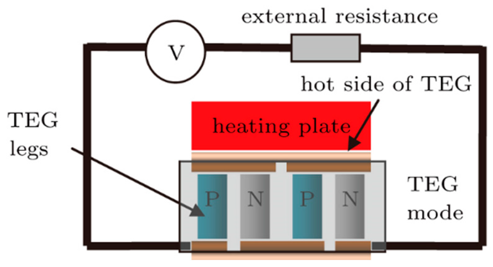
Figure 5.
Schematic representation of a photovoltaic–thermoelectric (PV-TE) system featuring an active cooling system. This diagram provides a detailed visual explanation of the system’s configuration and the functioning of its active cooling components.
Figure 5.
Schematic representation of a photovoltaic–thermoelectric (PV-TE) system featuring an active cooling system. This diagram provides a detailed visual explanation of the system’s configuration and the functioning of its active cooling components.
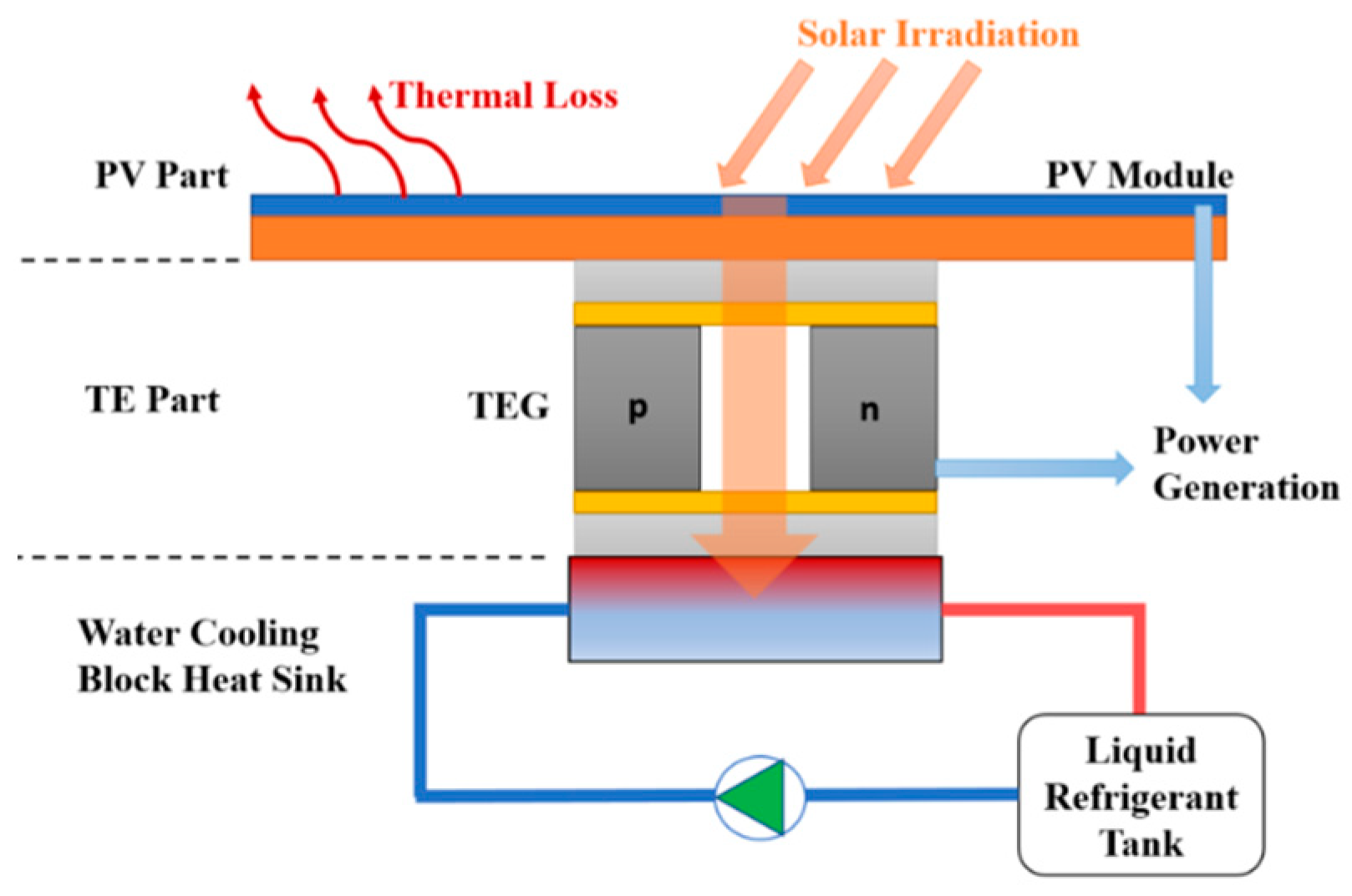
Figure 6.
(a) Current outputs of TEG3 without cooling system, with passive cooling system, and with active cooling system, under 50 °C Th; (b) voltage outputs of TEG3 without cooling system, with passive cooling system, and with active cooling system, under 50 °C Th.
Figure 6.
(a) Current outputs of TEG3 without cooling system, with passive cooling system, and with active cooling system, under 50 °C Th; (b) voltage outputs of TEG3 without cooling system, with passive cooling system, and with active cooling system, under 50 °C Th.
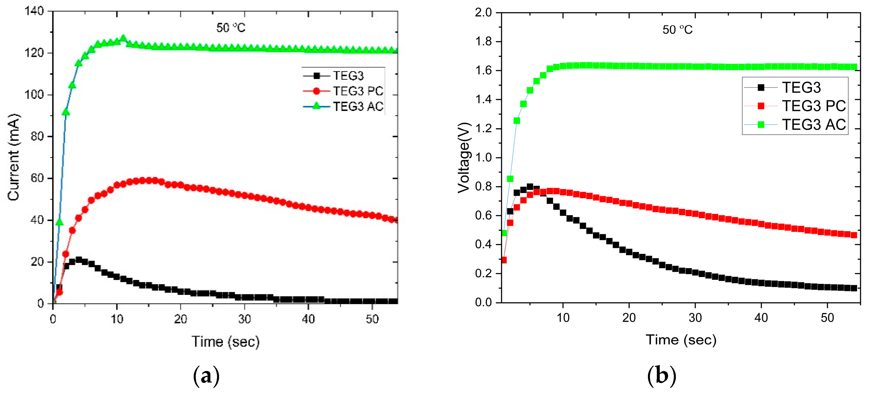
Figure 7.
(a) Current outputs of TEG4 without cooling system, with passive cooling system, and with active cooling system, under 50 °C Th; (b) voltage outputs of TEG4 without cooling system, with passive cooling system, and with active cooling system, under 50 °C Th.
Figure 7.
(a) Current outputs of TEG4 without cooling system, with passive cooling system, and with active cooling system, under 50 °C Th; (b) voltage outputs of TEG4 without cooling system, with passive cooling system, and with active cooling system, under 50 °C Th.
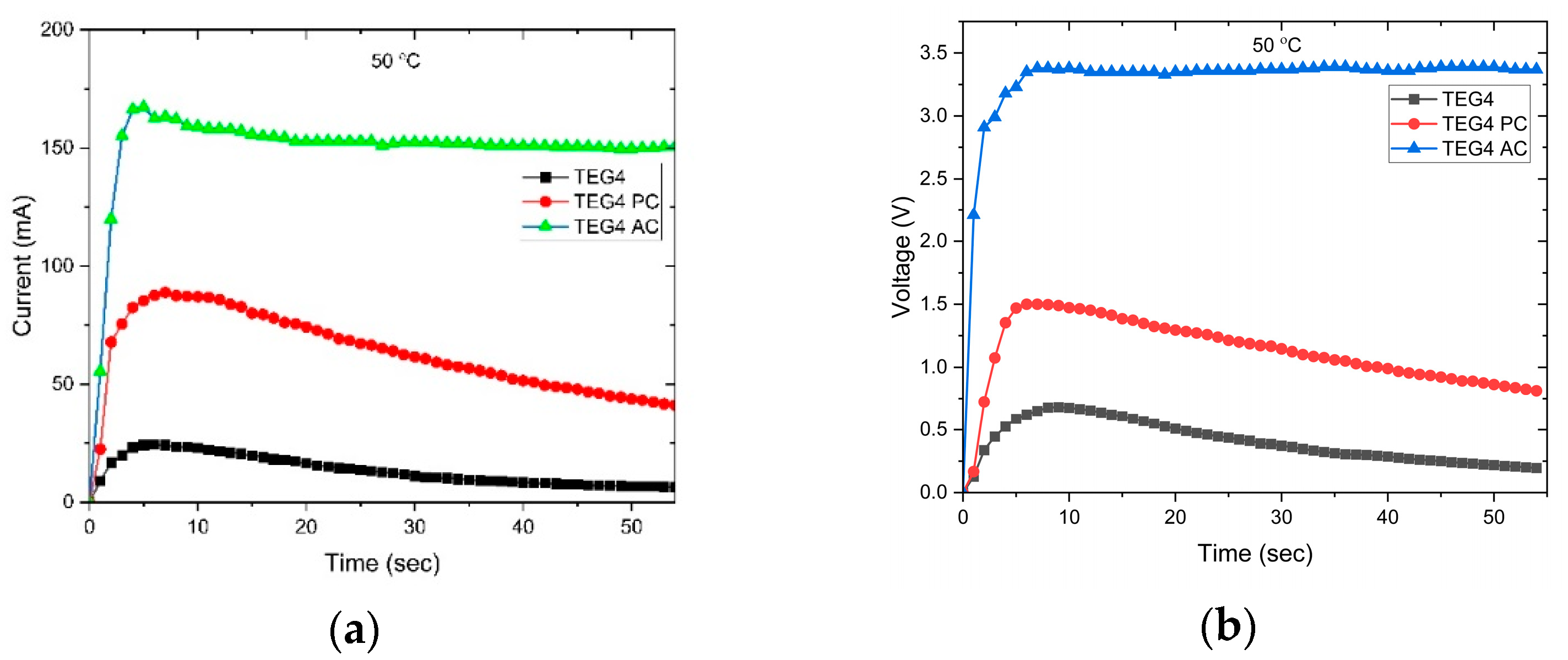
Figure 8.
(a) Power outputs of TEG3 without cooling system, with passive cooling system, with active cooling system, and with active cooling system with nanofluid, under 50 °C Th in mW; (b) power outputs of TEG4 without cooling system, with passive cooling system, with active cooling system, and with active cooling system with nanofluid, under 50 °C Th in mW.


Table 1.
Characteristics and dimensions of thermoelectric generators (TEGs) in study, including surface thickness and PN junction area thickness.
Table 1.
Characteristics and dimensions of thermoelectric generators (TEGs) in study, including surface thickness and PN junction area thickness.
| Name | Manufacturer | Thickness of TEG in mm | Thickness of Surface in mm | Thickness of PN Junction Area in mm | Model | TE Material | Plate Material |
|---|---|---|---|---|---|---|---|
| TEG1 | Hebei, Shanghai, China | 3.87 | 0.71 | 2.45 | TEC1-12706 | Bi2Te3 | Ceramic Al2O3 |
| TEG2 | Euroquartz, Shanghai, China | 3.71 | 0.73 | 2.25 | SP1848 27145 SA | Bi2Te3 | Ceramic Al2O3 |
| TEG3 | Kuongshun, Shenzhen, China | 3.77 | 0.71 | 2.35 | SP1848 27145 SA | Bi2Te3 | Ceramic Al2O3 |
| TEG4 | Adaptive, Leicestershire, UK | 3.59 | 0.89 | 1.81 | ETH-127-10-13-S-RS | Bi2Te3 | Ceramic Al2O3 |
| TEG5 | Marlow, Dallas, TX, USA | 3.9 | 0.7 | 2.5 | RC12 91826 | Bi2Te3 | Ceramic Al2O3 |
| TEG6 | TEC, Calgary, AB, Canada | 3.56 | 0.86 | 1.84 | TEG2-07025HT-SS | Bi2Te3 | Ceramic, graphite |
| TEG7 | TEC | 4.81 | 0.99 | 2.83 | TEG1-PB-12611 | Pb, Bi2Te3 | Ceramic, graphite |
Table 2.
Power outputs and performance increase of pure PV, PV-TE with TEG3 without cooling, PV-TE with TEG3 with passive cooling, and PV-TE with TEG3 with active cooling by using distilled water and nanofluid. (Ta = 25 Th = 50 Tc = 10).
Table 2.
Power outputs and performance increase of pure PV, PV-TE with TEG3 without cooling, PV-TE with TEG3 with passive cooling, and PV-TE with TEG3 with active cooling by using distilled water and nanofluid. (Ta = 25 Th = 50 Tc = 10).
| Product Test in 50 °C Ta | Power in W | Performance Increase |
|---|---|---|
| PV | 5.48 | |
| PV-TE TEG3 | 5.480107 | 0.00% |
| PV-TE TEG3 PC | 5.504732 | 0.45% |
| PV-TE TEG3 AC | 5.676746 | 3.59% |
| PV-TE TEG3 nAC | 5.682654 | 3.69% |
Table 3.
Power outputs and performance increase for pure PV, PV-TE with TEG4 without cooling, PV-TE with TEG4 with passive cooling, and PV-TE with TEG4 with active cooling by using distilled water and nanofluid. (Ta = 25 Th = 50 Tc = 10).
Table 3.
Power outputs and performance increase for pure PV, PV-TE with TEG4 without cooling, PV-TE with TEG4 with passive cooling, and PV-TE with TEG4 with active cooling by using distilled water and nanofluid. (Ta = 25 Th = 50 Tc = 10).
| Product Test in 50 °C Ta | Power in W | Performance Increase |
|---|---|---|
| PV | 5.48 | |
| PV-TE TEG4 | 5.480149 | 0.00% |
| PV-TE TEG4 PC | 5.503771 | 0.43% |
| PV-TE TEG4 AC | 5.987822 | 9.26% |
| PV-TE TEG4 nAC | 5.997978 | 9.45% |
Disclaimer/Publisher’s Note: The statements, opinions and data contained in all publications are solely those of the individual author(s) and contributor(s) and not of MDPI and/or the editor(s). MDPI and/or the editor(s) disclaim responsibility for any injury to people or property resulting from any ideas, methods, instructions or products referred to in the content. |
© 2024 by the authors. Licensee MDPI, Basel, Switzerland. This article is an open access article distributed under the terms and conditions of the Creative Commons Attribution (CC BY) license (https://creativecommons.org/licenses/by/4.0/).
Share and Cite
MDPI and ACS Style
Bulat, S.; Büyükbicakci, E.; Erkovan, M. Efficiency Enhancement in Photovoltaic–Thermoelectric Hybrid Systems through Cooling Strategies. Energies 2024, 17, 430. https://doi.org/10.3390/en17020430
AMA Style
Bulat S, Büyükbicakci E, Erkovan M. Efficiency Enhancement in Photovoltaic–Thermoelectric Hybrid Systems through Cooling Strategies. Energies. 2024; 17(2):430. https://doi.org/10.3390/en17020430
Chicago/Turabian StyleBulat, Selcuk, Erdal Büyükbicakci, and Mustafa Erkovan. 2024. "Efficiency Enhancement in Photovoltaic–Thermoelectric Hybrid Systems through Cooling Strategies" Energies 17, no. 2: 430. https://doi.org/10.3390/en17020430
Note that from the first issue of 2016, this journal uses article numbers instead of page numbers. See further details here.