
A Minimum Entropy Production Approach to Optimization of Tubular Chemical Reactors with Nature-Inspired Design

1
Institute of Aeronautics and Applied Mechanics, Warsaw University of Technology, 00-661 Warsaw, Poland
2
Department of Applied Mathematics, V.N. Karazin Kharkiv National University, 61000 Kharkiv, Ukraine
3
ING Hubs, 00-351 Warsaw, Poland
4
PoreLab, Department of Chemistry, Norwegian University of Science and Technology, NTNU, 7034 Trondheim, Norway
*
Author to whom correspondence should be addressed.
Energies 2024, 17(2), 432; https://doi.org/10.3390/en17020432
Submission received: 5 December 2023
/
Revised: 7 January 2024
/
Accepted: 11 January 2024
/
Published: 16 January 2024
(This article belongs to the Special Issue Research on Fluid Mechanics and Heat Transfer)
Abstract
:The problem of the shape optimization of tubular-type plug-flow chemical reactors equipped with a fluid flow-based cooling system is considered in this work. The hydraulic radius Rh(z) = 2A(z)/P(z) and an equivalent surface area-based radius Rs = P(z)/(2π) were computed from the cross-sectional area A(z) and perimeter P(z) measured along the nasal duct of Northern reindeer and used for shape optimization as nature-inspired design. The laminar flow in the cooling system was modeled using the Navier–Stokes equations for an incompressible liquid. In the central tube, a set of chemical reactions with temperature-dependent rates was considered. The temperature and flow velocity fields, pumping pressure, mass flow rate, and total heat flux Jth were obtained by numerical methods. Comparative analyses of the efficiency of different geometries were conducted on Pareto frontiers for hydraulic resistivity Zh, thermal resistivity Zth, thermal inlet length Lth, and entropy production Sirr as a sum of contributions from chemical reactions, thermal, and viscous dissipation. It was shown that the tube with Rs(z) as an interface between the reactor and cooler has the best Pareto efficiency using the (Zh,Zth,Lth) objective functions. Surprisingly, this design also exhibits the lowest Sirr and a more uniform distribution Sirr(z) (i.e., equipartition) among other designs. This geometry is suggested for densely packed tubular reactors.
1. Introduction
The recent rapid growth of air pollution by carbohydrate combustion and the consequent global climate changes have produced a large interest in efficient use of energy sources. One of the most important engineering ways to address the wish for increased efficiency is optimization of technological processes. Modifications in plant design and operating procedures have been implemented to reduce costs and meet constraints, with an emphasis on improving energy efficiency and increasing profitability of the energy sources. This includes optimization of chemical reactors, heaters/coolers, and other technical units. Reactor optimization cannot be achieved without considering the boundary conditions for the chemical and physical processes inside [1].
Chemical reactors are used for production of chemical substances. The chemical reactor is designed as an enclosed volume (or connected volumes) in which chemical/biochemical/polymer reactions take place at controlled physical conditions (pressure, temperature, humidity, pH, flow rate, etc.) or biological conditions (O2 and CO2 rates, ratio of food to microbial volumes, etc.) in bioreactors [2]. Existing chemical reactors have volumes ranging from a few mm3 (microreactors) in the laboratories to hundreds m3 in industrial plants [3]. The chemical reactions inside can be carried out in homogenous or inhomogenous systems at low/moderate/high temperatures and pressures [2,4]. The time scale is from milliseconds (ammonia oxidation to nitric acid) to days (biochemical reactions). Physical processes as crystallization/melting, evaporation/condensation/drying, and homogenization, in continuous or periodic regimes, can also be carried out in the reactors, for transformation of the initial substances into a product. The design of a chemical reactor is very important for its efficiency which is normally defined as the ratio of the net product amount to the total operating expense (raw material costs, energy input, energy removal, technical service). Bioreactors are in addition used to maintain comfortable conditioning for optimal growth of cell populations in the laboratory, for transplantology, tissue engineering, and other biomedical purposes [2,5]. Optimization of the size and shape of the reactor as well as the setting of operating physical conditions [6], temperatures, and temperature gradients [7,8] is an essential problem in chemical and biochemical engineering.
Chemical reactors are designed as vessels (tanks) in which the reactants can be injected and continuously mixed inside. In tubular reactors a solid catalyst in the form of particles or pellets is packed inside a tube forming a porous structure. Liquid or gaseous reactants are pumped through the tube and the chemical reactions are carried out in a laminar or turbulent flow of fluid through the pores between the catalytic particles. The chemical reactors could be constructed as stirred tanks, packed bed, or fluidized bed reactors, differential, batch, or piston-flow reactors; therefore, different approaches are needed for optimization of the unit. Their geometric design varies from single-bed to multibed and multitube units. Tubular reactors with slow laminar flow can be modeled as plug flow reactors with or without diffusion (i.e., negligible diffusion) [2]. The plug-flow reactors of either closed tubular types or open rectangular channels are used for different chemical processes including wastewater treatment [9,10]. This type of reactor has a smaller volume and minimum back mixing of product compared to the continuous-stirred tank reactors. The theory of plug-flow reactors is based on the assumption, that along the direction of the flow all the reactants and products move along at the same speed, and that there is no reverse flow [6].
An optimization of chemical reactors for desired products production at high rates is usually based on selection of pressure, temperature, and concentrations of different solvents; catalyst; type, shape, and size of the reactor; and transportation system for the reactants transfer into the reactor [6,11]. The cross-sectional area of the tube could be as small as approximately 1 mm2 [12] allowing a microfluidic approach to the flow description. The chemical reactions could be endo- or exothermic, and the corresponding heating or cooling system must be mounted at the sur face of the tube. The heat produced in exothermal chemical reactions can be used as an energy source for other purposes, making it an important issue for design optimization as well [2,4,6,13].
A promising approach to unit optimization is based on dynamic neural networks [14] and artificial intelligence [15]. A successful approach is based on nature-inspired solutions; using properties of natural reactors like lungs (O2 into CO2 conversion and removal) [16,17], nasal ducts (heating and moistening the inhaled air, and cooling and drying the exhaled air) [18], plant leaves (water delivery over short [19] and long [20] distances, and photosynthesis [21]), mitochondria (energy accumulation and distribution), biology-inspired chemical engineering [22,23], catalysis [24] based on tree-shaped flow structures, [25] and many others. The term nature-inspired is wider than the term biomimicking. The latter means just to copy geometry and operating conditions from a system in nature, while the former implies a deep understanding of the structure-functional relationship of a natural process/system, followed by its implementation with possible variations in both geometry and operating conditions. Nature-inspired design is rather an application of an idea, that nature has a properly designed engineered system, using efficiently the available materials, energy sources, operating conditions, unit maintenance, etc. The concept of nature-inspired chemical engineering developed in [18,23,26] implies a systematic design methodology to solve engineering problems, based on the fundamental understanding of physical mechanisms and their applications in engineering.
Biological organisms are interesting in this context because of their known high efficiency, scalability, robustness, and their adaptability. One may expect that these features have developed in the course of time (evolution) and included both geometry and function. A nature-inspired approach was confirmed to be a good solution for shape optimization of flying and underwater vehicles [27]. As main mechanisms underlying nature-inspired engineering, (i) hierarchical transport networks, (ii) force balancing, and (iii) dynamic self-organization have been discussed [24]. The main control mechanisms used by nature are (I) the optimal hierarchical pipelines with minimum energy costs for convective transport, (II) the accurate balances of forces at any scale for higher performance, and (III) the emergence of complex functions from simple components via dynamic evolution [24]. These mechanisms have been substantiated with nonequilibrium thermodynamics [28,29], the minimum entropy production approach [30], the nature-inspired design [31] with construct law [32,33], and nonlinear control theory [34].
2. Design Optimization in Chemical Engineering
2.1. Mathematical Formulations
Any optimization problem can be mathematically formulated as a minimization/maximization problem with a set of constrains:
where are the system parameters, are objective functions, are constrains in the form of equalities and/or non-equalities. The constraints could be divided into two classes: the first class contains the conservation equations (mass, momentum, etc.), and the second class contains the specific operational parameters like the pumping pressure, flow rate at the inlet, total production of the unit, etc. [29,30,35]. Accurate formulation of the constraints for both classes is essential for avoiding physically irrelevant results [36].
In the engineering literature, some practical approaches based on the measurable values and indexes are mostly discussed [37]. It is clear that both theoretical thermodynamic approaches and ‘technical’ or ‘engineering’ approaches are interconnected. In classical approaches to design and optimization of chemical reactors, the method of random variations with repetitive computations of the kinetic equations, fluid flow, diffusion, and heat conduction equations with least-squares analysis [1], genetic-, and gradient-based algorithms [38] are mostly used. The only entropic parameter estimated is the entropy change upon ideal mixing computed as , where R is the gas constant, is the mole fraction of j-th component in the mixture. Also, the steepest descent and conjugate gradient methods, linear programming, and heuristic search methods have been used for optimization of chemical processes [39]. The computation of chemical equilibria is considered as an optimization problem with minimization of Gibbs free energy G at constant temperature T and pressure p
where S and V are the entropy and volume, respectively, and are the chemical potential and number of moles of the j-th chemical component in the system. The principle of minimum work is also used in the optimization of chemical reactors and their cooling systems [38,39].
Optimization of design and operating parameters of the heat and mass exchangers, chemical reactors, engines, and micro [40] and nanofluidic systems [41,42] have been carried out with focus on the hydraulic resistance (), thermal resistance (), entropy production [43], and multicriteria optimization [44] including some combinations of both resistances in a general form with the weighting coefficients a, b. The Euler–Lagrange method can be applied to (1) to determine the distribution of local chemical products, which give minimum entropy production or the best second law-based efficiency [29].
where are the Lagrangian multipliers, δ is variation over the independent variables of the functions , and the constrains in the form of equalities.
The optimization problem is now formulated using optimal control theory [30,34,45]. In this theory, the state variables are divided into two groups, the state variables and the control variables. The state variables are governed by differential equations. The pressure of a gas is thus a state variable. The control variables are our handles on the system, or the means we control it. Optimal control theory gives a framework for how to handle the control variables, finding the state of minimum entropy production. Without any constraints imposed, the minimum is trivially zero.
2.2. Minimum Entropy Production Approach
In a case with several objective functions, Pareto frontiers (,) give a good approximation to best design solutions. The hydraulic resistance- and thermal resistance-based solutions of (1) produce different geometric designs for heat/mass exchange whether we use or as an optimization criterion [46]. The unified approach provided by the search for minimum entropy production () is then preferable [47]. The problem formulated by Equation (1) with two objective functions and can be reduced to deal with a single objective function , the entropy produced in all irreversible processes in the system. The combination of energy loss due to viscous flow, thermal dissipation, chemical reactions, and osmotic and electric processes is the new objective function.
The minimum entropy production approach was applied to a variety engineered units from heat/mas exchangers and bio/chemical reactors to pumps and turbines [48]. In some cases the optimization problem formulations and are equivalent. In endoreversible heat engines the criteria of minimum entropy production and maximum thermal efficiency gave the same optimal design at the condition of fixed heat input [49]. For reactive systems, the minimum entropy production rate approach is equivalent to maximum conversion rate [50]. In coupled multicomponent systems with diffusion and surface chemical reactions, the minimum entropy production approach allows determination of a stable steady state that can be realized in practice [51]. The equivalence of minimum entropy generation and maximum power production is limited to the constraints applied to the system and the ways of counting the entropy produced [52]. The minimum entropy production approach has also a dynamical interpretation. It was shown that the dynamics that minimize the entropy production are driven by conservative forces [53].
The minimum entropy production approach was successfully applied to optimization of the methanol synthesis via the carbon dioxide hydrogenation reactor [54], the ammonia synthesis reactor [55], the SO2 oxidation reactor [30], small modular reactors [1,4], tubular steam reformer [35,56,57], the reverse water-gas shift reactors [58,59], dimethyl ether synthesis reactors [60], catalytic combustion of air pollutants with Pd/Al2O3 catalyst [37], polymer electrolyte membrane fuel cells (FC) with Fermat spiral [61], biomimetic [62] and fractal-type [63] flow-fields, solid oxide FC [64], in ammonia-methane fueled micro-combustor for thermophotovoltaic applications [65], in hydrocarbon synthesis reactor with carbon dioxide and hydrogen [66], CO2 hydrogenation [67], isothermal crystallization processing [68], in the Fickett-Jacob cycle [69], diabatic distillation [70], in hydrogen iodide decomposition reactors heated by high-temperature helium [71], ideal reactors and practical industrial reactors [60,72], stirred tank and plug flow reactors [72], thermoelectric modules [73], heaters [13,74,75], and chillers [76]. Based on the minimum entropy production approach, a nanofluid-based tubular reactor was optimized to the elliptic shape with the axes ratio 5:3 that gave up to 16.82% reduction in the entropy production and rise in the thermal efficiency from 74% to 80% [77]. During the last few decades, the minimum entropy production approach has been recognized as an important design tool [78]. It was shown that the minimum entropy generation rate corresponds to the maximum output power for prescribed input heat and equivalent thermodynamic forces corresponded to current operating conditions [79]. Minimum entropy generation rate corresponds to maximum yield in sulfuric acid decomposition process [80].
The minimum entropy production approach is applicable to complex dynamical systems composed of multiple, interacting subsystems [81] with linear [82] and nonlinear [83] responses. The latter implies the thermodynamic transport coefficients depend on the corresponding external forces. The minimum entropy production principle gives an approximative variational characterization of close-to-equilibrium stationary states for both macroscopic systems and stochastic models. For the stochastic systems, the entropy generation can be defined as the general deviation rate function. In this case, the minimum entropy production rate is recognized as a consequence of the structure of dynamical fluctuations [84]. The minimum entropy production approach has been used for direct minimization of as a function of design parameters [47,85,86] and for entropy-based indices of efficiency [87]. The minimum energy dissipation rate principle can be derived from minimum entropy production principle [88]. The geometric constraints that minimize entropy production are the same that maximize the efficiency [73,89].
An equipartition theorem was formulated for the entropy production [90] and for thermodynamic forces [91] as good approximations [92] to the state of minimum total entropy production in parts of an optimally controlled system that has sufficient freedom to equilibrate internally, cf. ref. [93]. In a reactor with a single reaction, this implies that the chemical driving force, −ΔG/T [30], is uniform. In a heat exchanger, the thermal driving force is constant [94]. As a result, we can use the approach to find a good approximation to optimal heat and mass transfer, viscous flow friction, and chemical reactions [95]. This must be performed without regard for economic costs, because they are not a part of the entropy production. Anyway, such vital cost considerations must follow [75]. The total cost can also be used as an objective function (economic criterion) but separate from the thermodynamic optimization of the process unit [39].
It was shown, the minimum entropy production approach [95] and a fractal-type gas supply system [96] for a polymer electrolyte membrane FC can reduce in 75% the amount of catalyst required. The increase in the energy efficiency of this FC was in 10–20%. Further improvement of the geometric design for the fractal flow-field plate based on the same approach showed an even greater increase in the FC efficiency [62,63]. Minimization of the total entropy production of a membrane unit for CO2 separation from natural gas using optimal control theory has shown to be the optimal design, with total entropy reducing by 38% with respect to the reference case, and the methane losses reducing to zero [86]. The same approach was used in the application to the hydrogen production in a plug-flow chemical reactor with optimal design of its cooling/heating system [34]. Entropy-based optimization for the steam methane reforming reactor heated by molten salt allowed the energy loss reduction by 22.08% [57]. For the plug-flow reactors, it was shown that the profiles for the entropy production rate and its minimum at different wall temperatures follow the same trajectory, indicating that the reactor works at the minimum entropy conditions which is strongly recommended [97]. Also, the results indicated a positive correlation of the wall temperature and entropy production rate along the length of the tubular reactor.
Others have used Shannon’s formula for the design of chemical reactors and a description of their efficiency. The index of entropic performance (IEP) based on Shannon’s formula was proposed in the form [87].
where n is the total number of components. For a tubular reactor system, the corresponding function must be used instead of the Shannon’s entropy.
The hypothesis of equipartition formulated above was examined in membrane technology design optimizations [86,98]. Reductions in entropy production were achieved in several systems, fluid/gas transportation, heating/cooling, and chemical reactions. Some simplified solutions of the optimization problem for SO2 oxidation [29] and exothermal ammonia reactor [55] were formulated. It was shown, by varying the reactor length and controlling the utility, that reductions in the entropy production rate were achievable, up to 25% [30].
2.3. Shape Optimization and Nature-Inspired Solutions
Shape optimization of tubular reactors was applied to determine the optimal pipe diameter [39]. Shape variations, channel grooves [99], convergent–divergent [100], or more complex and irregular geometries [38] were studied. In metal hydride reactors, the convergent–divergent tube improved the performance slightly, compared to the straight tube reactor. A helical tube and conjugate helical tubes significantly lowered the temperature of the metal hydride bed [101]. The optimization of a chemical unit may need optimization of the cooling system. Choices include set of fins, cooling tubes, and use of materials with higher thermal conductivity [13].
A nature-inspired design was proposed for tubular-type plug-flow reactor for oxidation of SO2 [102] based on the anatomy of the nasal duct of the northern reindeer. Mature reindeer develop complex spiral structures along the maxiloturbinate area of their nasal duct. This structure provides fast heating of the inhaled cold air from ambient value up to the body temperature, +38.8 °C, and a moistening of up to 100% relative humidity [18]. The diameter profile d(x) along the reactor was found based on the measured cross-sectional area A(x) and perimeter P(x) of the nasal duct. Compared to a tubular reactor with constant cross-sectional are, a reduction of 11% in the total entropy production was observed. The reactor length proposed from the optimization, resulted in an additional reduction in by 16% [102]. Numerical computations were performed on a 1D model of the plug flow along the duct. The computed profiles of temperature, pressure, velocity and concentrations of the chemicals were used in the calculation of the entropy production, before and after introduction of nature-inspired design.
Profiles of variables along the reactor tube can be obtained with various realistic geometries, in reference and optimal cases, using computational fluid dynamics (CFD). This method allows also a scaling-up of laboratory reactor designs to larger volumes [103]. A modification of the reactor design for conversion of CO2 methanation into synthetic methane was, for instance, computed in a free convection multi-tubular reactor, in a CFD simulation of a single reactive channel (d = 1/40, H = 300 mm). A hexagonal shaped distribution of 23 reactive channels separated by a distance of 40 mm was proposed [103].
In the present paper, a tubular design with non-constant diameters of both reactor area (inner tube) and cooling system (external tube) is studied. As input geometric variables, the geometric measures obtained from the Northern reindeer nasal duct are used. The motivation for doing this is that the reindeer’s nose is an excellent natural heat exchanger. The idea is that a surface-to-volume ratio P(z)/A(z) obtained from nature is a ratio resulting from evolution in a harsh climate. The hypothesis can afterwards be tested by comparing the performance of this system to the case having a simple axisymmetric geometry d = const.
The entropy production will next be used as objective function in combination with classical thermophysical choices. Flow parameters (temperature, mass, and heat flux) will be obtained from 3D CFD numerical computations. As objective functions, the entropy production, thermal inlet length, hydraulic resistance, and thermal resistance of the system are studied. The target is the geometric design with highest efficiency. The most efficient system is thus the system with the lowest energy dissipation in the thermal, viscous, and chemical reactions combined. As starting point, a reactor operated at steady state with the same settings as used before [102] is considered. The shape of the tubular reactor was optimized in [102], leading to a nature-inspired design. Here, the optimized design of the reactor and cooler combined, with varying constraints and boundary conditions, but with geometric variables inspired by nature as input is considered.
3. Problem Formulation
The base case reactor is composed of two coaxial cylinders. The inner tube is filled with a bed packed with catalytic particles. The cooling system is located between the tubular walls (Figure 1a). In the base case the outer and inner cylinder radii, Rint, Rext, are constant (Figure 1a) with a radius and length scale Rin:L = 1:10. The outer cylinder has a radius according to Rext:Rint = 1.5:1. This is compatible with the non-dimensional size of many different laboratory and industrial plug-flow reactors [1,6,11,39]. Transport of the reactant (fluid flow) takes place along the z-axis, while transport of heat takes place in the radial direction. Figure 1b shows the two radii Rint = 1, Rext = 1.5 of the BCR, as well as two nature-inspired radii Rh(z) and Rs(z) (solid line and dotted line, accordingly).
Two nature-inspired designs were applied, both using a radius that varies along the tube. In the first case, with a cross-sectional area A(z) and perimeter P(z) both taken from the nasal duct of mature Northern reindeers [18]. The surface area between the reactor (I) and the cooler (II) is important for heat transfer from the reactor to circulating fluid in the cooler. Therefore, in the second case, the reactor tube has constant cross-sectional area and a varying perimeter everywhere, as in the reindeer’s nasal duct, giving a surface-based radius (Figure 1b). Both and were scaled to the values 1 and 1.5 for the internal and external tubes, accordingly.
Nine combinations of the base case reactor with nature-inspired geometries were designed (see Figure 2). These were either constant or computed from or (Table 1). Both choices for nature-inspired geometries in Figure 1b are noticeably different from straight cylinders. The tubes are narrower at the inlets and wider near their outlets compared to the straight tubes. The numerical results computed on the chosen nature-inspired geometry will be compared to the corresponding data computed on the base case reactor with constant and . It is suggested that the nature-inspired geometry can produce a relationship between the volumetric flow and the heat conduction which translates into a smaller entropy production, as it was shown in [102] for the tubular reactor without cooling.
The outer surface of the cooler was chosen to be adiabatic, therefore, all heat produced in the chemical reactions was taken out by the coolant flow. The raise in temperature of the coolant could be used as an energy source for other units of the chemical plant.
The geometries were created in AnSys Fluent 2023 Geometry Modeler (Ansys, Inc.®, Canonsburg, PA, USA). With the circular geometry of both tubes, axisymmetric flows in (x,z)-coordinates of the reactant through the reactor (I in Figure 1a) and of the coolant through the cooler (II in Figure 1a) are assumed.
Chemical plug-flow reactor for SO2 oxidation (SO2 + 0.5O2 → O3) was considered. The reaction is exothermic. The reactant liquid was modelled as passing through a porous catalyst following the work [102].
where , , , , , , , and are the efficient density, pressure, velocity, temperature, heat conduction coefficient and specific heat capacity at constant pressure in the reactor (region I); accordingly, is the porosity of the region I composed by spherical particles (pellets) of the diameter Dp, is the reaction rate per unit mass of the catalyst, is the reaction enthalpy, is the viscosity of the gas fuel, , is the molar flow rate of the chemical component i.
The steady flow of the coolant was described by the Navier–Stokes equations for an incompressible fluid.
where and are the density and viscosity of the fluid, and are the hydrostatic pressure and velocity field in the cooler (II).
The flow in the reactor (I) was also described by Equation (6) with the density , viscosity , pressure , and velocity of the reactant fluid in a porous medium with porosity composed by the catalyst particles. In the case of gas fuel, the compressible mass balance equation must be used instead of the first Equation (6).
The temperature equation in the cooler (region II) is
where TII is the temperature, and are the specific heat capacity at constant pressure and the heat conduction coefficient, , is the dissipation to heat due to viscous stress, , is the shear stress tensor in the region II.
The boundary conditions for Equations (6) and (7) were (both regions)
Here, was taken as a parabolic inflow function for faster convergence to the steady state regime, and were chosen according to the optimal preheated fuel flow and a cold coolant with , accordingly.
The solution of the system of nonlinear partial differential Equations (5)–(7) with boundary conditions (8)–(11) can be obtained by numerical methods only. The AnSys Fluent 2023 R2 (Ansys, Inc.®, Canonsburg, PA, USA) software provides an easy and efficient geometry modeling and mesh generation for the fluid flow in complex solid and elastic geometry with heat conduction. The semi-analytical solution of the combined fluid flow with heat transfer is available for the flow between two co-axial cylinders (i.e., base case reactor) (Figure 2a) [104]. An analytical solution for the axisymmetric flow through the base case reactor without heating is known as a flow through annulus. It has well known analytical solution [105] that will be used for validation of the numerical model (5)–(11) without thermal dissipation.
The solution of Equations (5)–(7) for both regions I and II with boundary conditions (8)–(11) gives all the variables needed for calculations of the hydraulic resistance;
and the thermal resistance
where is the axial component of the velocity in the j-th region, and V is the volume, j = {I,II}.
Due to the difference in the temperature of the fuel and coolant at the inlet, a thermal boundary layer will develop in area II. The average value <TII> will increase with axial distance from the inlet, and at some z = Lth a maximum value <TII> will be achieved. Therefore, <TII> = const at z > Lth; with Lth as the thermal entry length (thermally fully developed region, with the coolant heated to maximal temperature at given operating conditions). It is worth to note that at a slow flow of the coolant, cases with Lth > L could happen. In the optimal system, a correspondence Lth ~ L is desirable. When Lth << L, the coolant no longer (at z > Lth) serves to cool the reactor. Likewise, when Lth >> L, the coolant is not heated enough to be used as an energy source. The condition Lth ~ L can be achieved by varying the inlet temperature and the flow rate of the coolant (i.e., changing operating conditions).
The values Zh, Zth, and Lth were all used as objective functions for the same total system volume, as constraint. Since the optimization criteria could be contradictory (that was shown to be the case for the pair (Zh, Zth) [46]) the Pareto method was also applied, and three optimization problems were considered:
For all geometries, fixed boundary conditions {,,,,,,} = const and the total volume V of the system has been chosen, while in [102], the volume of the reactor and ambient temperature were chosen as constrains.
The total entropy production in the system was computed from
where and are the Gibbs energy change and the rate of the chemical reaction k = 1, 2, …, p in the reactor, is the stress tensor. This expression for the entropy production was used as the forth objective function in the optimization problem.
The profiles of were computed for each geometry (Figure 2) and compared. Based on (15), the following pairs of objective functions , , and were also studied.
4. Numerical Method
A uniform fine mesh was generated in the reactor, cooler, and outer adiabatic wall with inflation to the interfaces (10 layers from both sides of each interface); see Figure 3. This was completed in order to accurately determine large near-wall gradients of the variables. The mesh was also used for calculations of heat conduction through the non-adiabatic external surface in the case of more complex design of the chemical reactor with non-adiabatic boundary conditions. The number of finite elements and nodes varied in the ranges nFE = (7–9) × 104 and nnode = (14–20) × 104, respectively. The mesh sizing of (0.2–2) × 10−3 was chosen. Different types of chemical kinetics (5) with given values υA,B,C were taken from the AnSys Fluent database of fuels. The most common chemical plug-flow reactors for oxidation of SO2 and ethylene production had water cooling of TII,0 = 273 °K. The inner tube was modeled as a uniform medium with porosity . The parabolic inflow of the coolant and the reaction rate per unit mass of catalyst were assigned in AnSys Fluent as user-defined functions.
First and second order upwind numerical schemes for the momentum equations and the standard scheme for the pressure and temperature with the least square method for gradients of the valuables (6)–(7) with accuracy 10−5 were tested. The mesh-independence test for the problem solution was carried out. The sizing (1–2) × 10−3 and the number of nodes, nnode ~15 × 104, was found reasonable from the point of view the computation time and accuracy. The test on scheme-independence of the solution was carried out. The first-order scheme for the momentum equations was found accurate enough with faster convergence.
The numerical scheme was validated with known semi-analytical results for the steady state flow between two coaxial cylinders with constant temperature at the wall. Recommended flow rates, fuel temperature TI,0, and steady reactor temperature max(TI) for different chemical reactions were taken from literature [1,39,102]. The resulting Reynolds number in the reactor varied in the range ReI = 2–20. The flow rate of the coolant was chosen based on numerical results of the relation between Lth and L. At high flow rates of the coolant (ReII > 100), the thermal inlet length was too long (Lth >> L), and the chosen length of the reactor was not enough for a proper heating of the coolant. Therefore, according to the estimated Reynolds numbers, the laminar flow model was taken for the coolant flow. In the tubes with varying diameters, the model produced physically relevant results with vortex formations in the convergent and divergent regions of the tube.
5. Results and Discussion
The numerical results, which were obtained for the nine geometries (Figure 2) of the SO2 oxidation reactor, are shown in Figure 4, Figure 5, Figure 6, Figure 7, Figure 8 and Figure 9. Figure 4 presents temperature contour plots for the Geom1 in four different flow parameters. The tube in Figure 4a shows the effect of the exothermal chemical reaction, initiated by the fuel flow at the inlet temperature TI,0. There is a fast increase in the temperature at the entrance to the reactor (Figure 4a) (see [29,104]). At low TII,0 ~ 273 K and TI,0 ~ 278 K, the temperatures in both tubes are much lower (Figure 4b). When TII,0 is low and QII is small, the inlet thermal length is short, and the coolant will not efficiently transfer heat from the reactor (Figure 4c). In the opposite case, the thermal inlet length could be too long, and the coolant will not be heated enough to serve as a heat source for further utilization (Figure 4d). In that way, numerical simulations allow for the selection of the best choice of the operating parameters TII,0 and QII, which are dependent on the length and type (chemical reaction) of the reactor.
The vector plots for velocity vectors, x0y plots for the cross-section averaged distributions <TI,II>(z), <p(z)>, <Sirr>(z), and the volume-averaged values of Zh, Zth and have also been computed with AnSys Fluent (Ansys, Inc.®, Canonsburg, PA, USA). The detailed plots are presented in the Supplementary Materials. All computed dependences were found physically relevant, as demonstrated by Figure 5, Figure 6, Figure 7, Figure 8 and Figure 9.
The Pareto frontiers for geometries 1–9 (Figure 2), derived from solutions of the optimization problems (1)–(3) in (14), and their combinations with the entropy production in the total system are presented for the most promising solutions in Figure 5, Figure 6 and Figure 7. For each pair of objective functions, there exists a determined geometry with minimum in both functions. The results for the pairs (,) and (,) are presented in Figure 8 and Figure 9. The best solutions with reasonable low values for both optimization criteria are marked by circles in Figure 5a, Figure 6a and Figure 7a. The geometry of the tubes and the best flow patterns for the coolant are given in Figure 5b, Figure 6b and Figure 7b. The results of the best choice for each pair are summarized in Table 2. Geometry 5 does not give a good solution for any of the pairs of objective functions while geometries 1 and 3 satisfy three pairs each. The best shape is given by Geometry 7 which exhibits the best choice for 4 pairs of the optimization criteria. This geometry is located not far from the best Pareto solutions (Figure 8).
The results obtained conform with previously proposed nature-inspired designs for plug flow chemical reactors [102]. They can also be said to support results for reactors where the surface area has been modified with straight grooves [99] or irregular changes [4]. The results confirm that a non-straight geometry improves the overall heat conduction by coolant mixing, thereby reducing the total entropy production. The smaller inlet radius of the tube becomes, as it does in the data we have taken from nature, the smaller the temperature gradients between the reactor (I) and cooler (II) become. Cooling can take place at lower temperature. A widening of the tubes near the outlets provides higher flow rate of the already heated coolant with lower entropy production.
6. Conclusions
A thermodynamic optimization has been carried out of the plug flow chemical reactor with heat exchange. The entropy production has been used as objective function, and its impact on different design issues has been discussed. Minimum entropy production is equivalent to minimum energy dissipation, as well as to maximum efficiency, when boundary conditions are held constant. Numerous examples of successful shape, size, control variables, constraints, and operating conditions optimization based on the approach are reviewed and tested.
The search for a steady state operation with reduced entropy production was also inspired by work on a natural process unit. Here, the reindeer nose was taken as example. The result conforms with the highway hypothesis, stating that it is beneficial to have a constant entropy production away from the boundaries [29,30]. The most energy efficient solution to the Pareto defined optimization problem (including the entropy production) was a solution with rather uniform entropy production along the reactor tube. This knowledge may be useful for improvement of energy efficiency of chemical reactions. The energy efficiency of interest here is quantified by the energy dissipation as heat in surroundings, or the entropy production.
This work has demonstrated an optimization procedure that could be systematically implemented for design of exothermic and endothermic chemical reactors. By including the entropy balance and the entropy production minimization procedure in the set of balance equations to be solved, the method of analysis adds to the general engineering toolbox. While much computer efforts are needed to accomplish this, the added focus on energy efficiency may still bring the field of reactor design to a new level.
A novel design is proposed for the tubular plug-flow chemical reactor, obtained with input of geometric data from the nasal duct of the Northern reindeer (nature-inspired design). Rather than using a cylinder-shaped tube with constant radius, a tube with varying radii of both reactor and cooling tube around should be used. Different design combinations were compared, using Pareto optimal sets in combination with the minimum entropy production approach. The solution with the lowest value for the total entropy production has a more uniform entropy production in agreement with earlier observations [29,30]. This observation, which also characterizes the nature-inspired set of conditions, may therefore be of relevance to other process units.
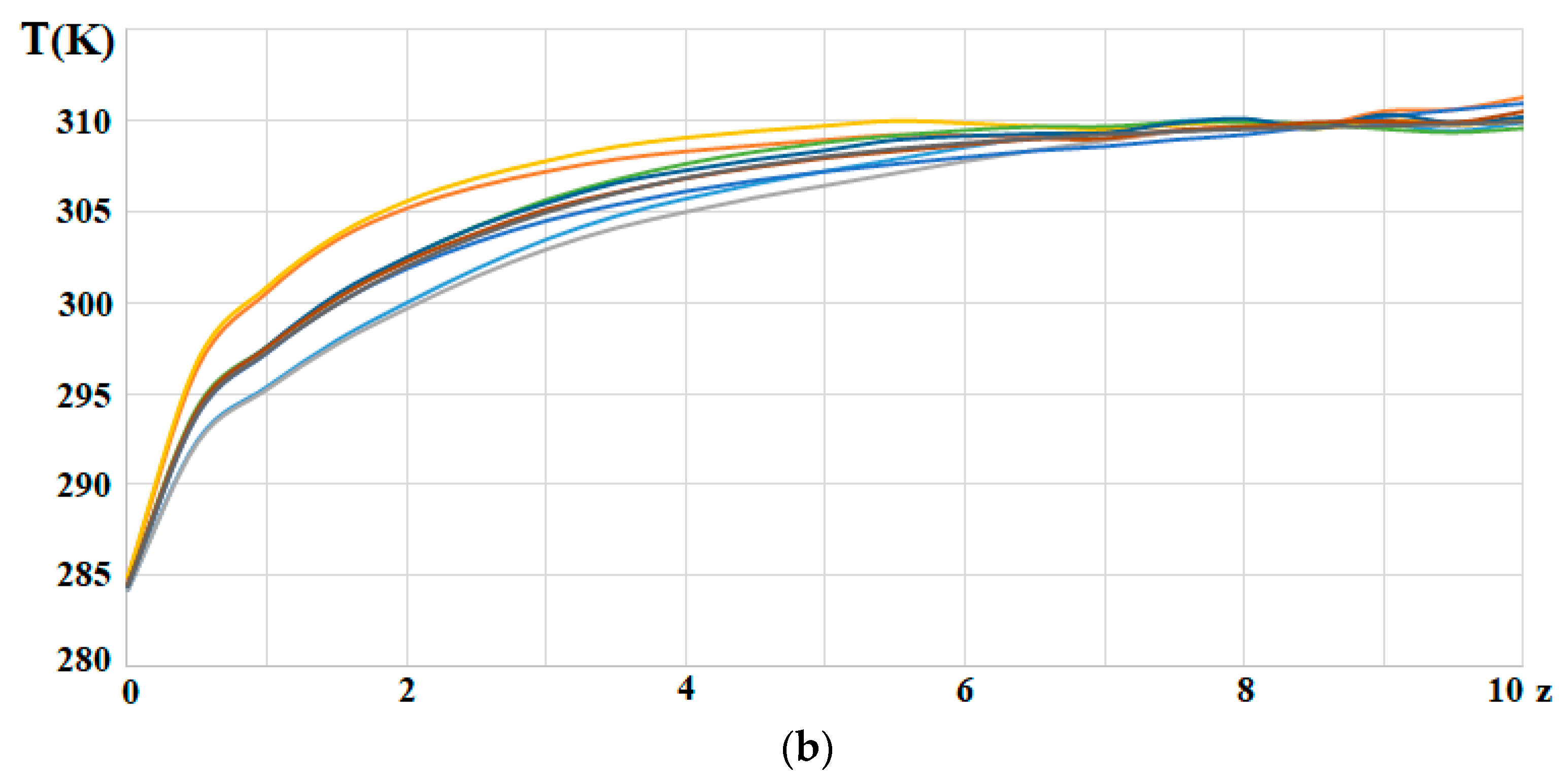
To use this knowledge is simple and fast, thereby creating a method for efficiency optimization of chemical and biochemical reactors in terms oof reactor shape. Possible applications span from large industrial units to micro/nanofluidic-based systems. Here, the dependence of cross-sectional area S(z) on z shows quite a high entropy production before reaching the distance ~0.2 L from the inlet (Figure 10a). It is known from the literature that in chemical reactors, the contribution to entropy production from heat transfer is often the largest source for energy dissipation (pp. 201–203 in [29]). The first step in a strategy to increase the energy efficiency in the reactors is to make the heat transfer as efficient as possible. An algorithm that split the base case chemical reactors and their cooling systems into a series of heat exchanger, adiabatic reactor, heat exchanger, and tubular reactor was therefore proposed. One may speculate that a similar behavior serves the same purpose in Nature. The air humidification in the nasal duct of Northern reindeer obtains, for instance, a remarkable fast and energy-saving process, by having an inlet narrower than the outlet. This is where most of the heating/cooling take place. This may suggest that there is much to learn from natural design in engineering. The results obtained in the study should be validated on laboratory prototypes of the tubular shapes that are planned for future studies.
Supplementary Materials
The following supporting information can be downloaded at: https://www.mdpi.com/article/10.3390/en17020432/s1, Figure S1: Tubular reactors; Figure S2: Development of thermal boundary layer; Figure S3: Temperature profile along the axis of the tube; Figure S4: Mesh-independence test; Figure S5: Temperature contour plots for the mesh-independent test; Figure S6: Temperature profiles for the mesh-independent test; Figure S7: Contour plots of the pressure distribution in the cylindrical reactor (Geom1); Figure S8: Contour plots of temperature distributions in different geometries; Table S1: Mesh details.
Author Contributions
Supervision, Project administration, Methodology, Investigation, Writing—original draft—N.K.; Geometry design, Software, Visualization, Validation, Data curation, Investigation—A.S.; Methodology, Formal analysis, Investigation, Writing—review and editing—S.K. All authors have read and agreed to the published version of the manuscript.
Funding
S.K. is grateful to the Research Council of Norway for its Center of Excellence Funding Scheme, project no 262644, PoreLab.
Data Availability Statement
Data supporting reported results can be found as Supplementary Materials.
Acknowledgments
S.K. and N.K. are grateful to the colleagues from the Centre of Excellence PoreLab of Norwegian University of Science and Technology (NTNU) for fruitful discussions on the topic.
Conflicts of Interest
The authors declare no conflicts of interest. The funders had no role in the design of the study; in the collection, analyses, or interpretation of data; in the writing of the manuscript; or in the decision to publish the results.
References
- Nauman, E.B. Chemical Reactor Design, Optimization, and Scaleup; McGraw Hill: New York, NY, USA, 2002. [Google Scholar]
- Singh, L.; Mahapatra, D.M. (Eds.) Bioreactors; Elsevier: Amsterdam, The Netherlands, 2020. [Google Scholar]
- Li, Y.-H.; Kao, H.-H.; Wang, Y.-R.; Wan, J.; Manatura, K. Performance optimizing and entropy generation analysis of a platinum–stainless-steel segmented microreactor. Chem. Eng. J. 2023, 457, 141151. [Google Scholar] [CrossRef]
- Salmi, T.O.; Mikkola, J.-P.; Wärnå, J.P. Chemical Reaction Engineering and Reactor Technology, 2nd ed.; CRC Press: London, UK, 2019. [Google Scholar]
- Kizilova, N.; Rokicki, J. 3D Bioreactors for cell culture: Fluid dynamics aspects. In Biomechanics in Medicine, Sport and Biology; Hadamus, A., Piszczatowsky, S., Syczewska, M., Blazkiewicz, M., Eds.; Springer Series Lecture Notes in Networks and Systems; Springer: Cham, Switzerland, 2022; Volume 328, pp. 80–99. [Google Scholar]
- Liu, S. Bioprocess Engineering. Kinetics, Sustainability, and Reactor Design, 2nd ed.; Elsevier B.V.: Amsterdam, The Netherlands, 2017. [Google Scholar]
- Bilous, O.; Amundson, N.R. Optimum temperature gradients in tubular reactors—I. Chem. Eng. Sci. 1956, 5, 81–92. [Google Scholar] [CrossRef]
- Bilous, O.; Amundson, N.R. Optimum temperature gradients in tubular reactors—II. Chem. Eng. Sci. 1956, 5, 115–126. [Google Scholar] [CrossRef]
- Buzatu, P.; Lavric, V. Submerged membrane bioreactors for wastewater treatment: Multi-objective optimization. Chem. Eng. Trans. 2011, 25, 267–272. [Google Scholar]
- Pal, P. Industrial Water Treatment Process Technology; Elsevier: Amsterdam, The Netherlands, 2017. [Google Scholar]
- Doran, P.M. Bioprocess Engineering Principles, 2nd ed.; Elsevier: Amsterdam, The Netherlands, 2013. [Google Scholar]
- Mierdel, K.; Jess, A.; Gerdes, T.; Schmidt, A.; Hintzer, K. Energy and resource efficient production of fluoroalkenes in high temperature microreactors. ChemEngineering 2019, 3, 77. [Google Scholar] [CrossRef]
- Kudiiarov, V.; Elman, R.; Pushilina, N.; Kurdyumov, N. State of the art in development of heat exchanger geometry optimization and different storage bed designs of a metal hydride reactor. Materials 2023, 16, 4891. [Google Scholar] [CrossRef] [PubMed]
- Becker, T.; Enders, T.; Delgado, A. Dynamic neural networks as a tool for the online optimization of industrial fermentation. Bioprocess Biosyst. Eng. 2002, 24, 347–354. [Google Scholar]
- Chen, L.Z.; Nguang, S.K.; Chen, X.D. Modelling and Optimization of Biotechnological Processes: Artificial Intelligence Approaches; Springer: Heidelberg, Germany, 2010. [Google Scholar]
- Trogadas, P.; Coppens, M.-O. Nature-inspired electrocatalysts and devices for energy conversion. Chem. Soc. Rev. 2000, 49, 3107–3141. [Google Scholar] [CrossRef]
- Trogadas, P.; Xu, L.; Coppens, M.-O. From biomimicking to bioinspired design of electrocatalysts for CO2 reduction to C1 products. Angew. Chem. Int. Ed. 2023, 63, e202314446. [Google Scholar] [CrossRef]
- Solberg, S.B.B.; Kjelstrup, S.; Magnanelli, E.; Kizilova, N.; Barroso, I.L.C.; Acquarone, M.; Folkow, L. Energy-efficiency of respiration in mature and newborn reindeer. J. Comp. Physiol. Ser. B 2020, 190, 509–520. [Google Scholar] [CrossRef]
- Kizilova, N. Construction principles and control over transport systems organization in biological tissues. In Physics and Control; Fradkov, A.L., Churilov, A.N., Eds.; IEEE Computer Society: Washington, DC, USA, 2003; Volume 1, pp. 303–308. [Google Scholar]
- Kizilova, N. Long-distance liquid transport in plants. Proc. Est. Acad. Sci. Ser. Phys. Math. 2008, 57, 179–203. [Google Scholar] [CrossRef]
- Andriesse, C.; Hollestelle, M. Minimum entropy production in photosynthesis. Biophys. Chem. 2001, 90, 249–253. [Google Scholar] [CrossRef] [PubMed]
- Chen, X.D. Scoping biology-inspired chemical engineering. Chin. J. Chem. Eng. 2016, 24, 1–8. [Google Scholar] [CrossRef]
- Coppens, M.-O. Learning from nature in building sustainable chemical technology. WIT Trans. Ecol. Environ. 2004, 73, 349–358. [Google Scholar]
- Coppens, M.-O. A nature-inspired approach to reactor and catalysis engineering. Curr. Opin. Chem. Eng. 2012, 1, 281–289. [Google Scholar] [CrossRef]
- Miguel, A.F. A study of entropy generation in tree-shaped flow structures. Int. J. Heat Mass Transf. 2016, 92, 349–359. [Google Scholar] [CrossRef]
- Coppens, M.-O. Multiscale nature inspired chemical engineering. In Multiscale Methods—Bridging the Scales in Science and Engineering; Fish, J., Ed.; Oxford University Press: Oxford, UK, 2009; pp. 536–560. [Google Scholar]
- Raja, V.; Prakash, A.; Kumar, A.; Pacheco, D.A.d.J. Multi-disciplinary engineering design of a high-speed nature-inspired unmanned aquatic vehicle. Ocean. Eng. 2023, 270, 113455. [Google Scholar] [CrossRef]
- Gerbaud, V.; Shcherbakova, N.; Da Cunh, S. A nonequilibrium thermodynamics perspective on nature-inspired chemical engineering processes. Chem. Eng. Res. Des. 2020, 154, 316–330. [Google Scholar] [CrossRef]
- Kjelstrup, S.; Bedeaux, D.; Johannessen, E.; Gross, J. Non-Equilibrium Thermodynamics for Engineers; World Scientific: Singapore, 2017; pp. 180–181. [Google Scholar]
- Johannessen, E.; Kjelstrup, S. A highway in state space for reactors with minimum entropy production. Chem. Eng. Sci. 2005, 60, 3347–3361. [Google Scholar] [CrossRef]
- Bejan, A. Shape and Structure, from Engineering to Nature; Cambridge University Press: Cambridge, UK, 2000. [Google Scholar]
- You, J.; Feng, H.J.; Chen, L.G.; Xie, Z.H. Constructal design of nonuniform heat generation area based on triangular elements: A case of entropy generation minimization. Int. J. Therm. Sci. 2019, 139, 403–412. [Google Scholar] [CrossRef]
- Zhang, F.Y.; Feng, H.J.; Chen, L.G.; You, J.; Xie, Z.J. Constructal design of an arrow-shaped high thermal conductivity channel in a square heat generation body. Entropy 2020, 22, 475. [Google Scholar] [CrossRef] [PubMed]
- Wilhelmsen, Ø.; Johannessen, E.; Kjelstrup, S. Energy efficient reactor design simplified by second law analysis. Int. J. Hydrogen Energy 2010, 35, 13219–13231. [Google Scholar] [CrossRef]
- Nummedal, L.; Røsjorde, A.; Johannessen, E.; Kjelstrup, S. Second law optimization of a tubular steam reformer. Chem. Eng. Process Intensif. 2005, 44, 429–440. [Google Scholar] [CrossRef]
- Bertola, V.; Cafaro, E. A critical analysis of the minimum entropy production theorem and its application to heat and fluid flow. Int. J. Heat Mass Transf. 2008, 51, 1907–1912. [Google Scholar] [CrossRef]
- Korpyś, M.; Gancarczyk, A.; Iwaniszyn, M.; Sindera, K.; Jodłowski, P.J.; Kołodziej, A. Analysis of entropy production in structured chemical reactors: Optimization for catalytic combustion of air pollutants. Entropy 2020, 22, 1017. [Google Scholar] [CrossRef] [PubMed]
- Pereira Rosinha Grundtvig, I.; Daugaard, A.E.; Woodley, J.M.; Gernaey, K.V.; Krühne, U. Shape optimization as a tool to design biocatalytic microreactors. Chem. Eng. J. 2017, 322, 215–223. [Google Scholar] [CrossRef]
- Edgar, T.F.; Himmelblau, D.M.; Lasdon, L.S. Optimization of Chemical Processes, 2nd ed.; McGraw-Hill: New York, NY, USA, 2001. [Google Scholar]
- Awad, M.M. A review of entropy generation in microchannels. Adv. Mech. Eng. 2015, 7, 168781401559029. [Google Scholar] [CrossRef]
- Rashidi, M.M.; Nasiri, M.; Shadloo, M.S.; Yang, Z. Entropy generation in a circular tube heat exchanger using nanofluids: Effects of different modeling approaches. Heat Transf. Eng. 2017, 38, 853–866. [Google Scholar] [CrossRef]
- Alsarraf, J.; Shahsavar, A.; Babaei Mahani, R.; Talebizadehsardari, P. Turbulent forced convection and entropy production of a nanofluid in a solar collector considering various shapes for nanoparticles. Int. Commun. Heat Mass Transf. 2020, 117, 104804. [Google Scholar] [CrossRef]
- Bejan, A. Entropy Production through Heat and Fluid Flow; Wiley: New York, NY, USA, 1982. [Google Scholar]
- Stadler, W. Multicriteria Optimization in Engineering and in the Sciences; Mathematical Concepts and Methods in Science and Engineering; Springer Science & Business Media: New York, NY, USA, 1988; Volume 37. [Google Scholar]
- Nummedal, L. Entropy Production Minimization of Chemical Reactors and Heat Exchangers. Ph.D. Thesis, Department of Chemistry, Norwegian University of Science and Technology, Trondheim, Norway, 2001. [Google Scholar]
- Wechsatol, W.; Lorente, S.; Bejan, A. Tree-shaped flow structures: Are both thermal-resistance and flow-resistance minimisations necessary? Int. J. Exergy 2004, 1, 2–17. [Google Scholar] [CrossRef]
- Bejan, A. Entropy Production Minimization: The Method of Thermodynamic Optimization of Finite-Size Systems and Finite-Time Processes; Advanced Topics in Mechanical Engineering; Kulacki, F.A., Ed.; CRC Press: Boca Raton, FL, USA, 1996. [Google Scholar]
- Zhou, L.; Hang, J.; Bai, L.; Krzemianowski, Z.; El-Emam, M.A.; Yasser, E.; Agarwal, R. Application of entropy production theory for energy losses and other investigation in pumps and turbines: A review. Appl. Energy 2022, 318, 119211. [Google Scholar] [CrossRef]
- Haseli, Y. The equivalence of minimum entropy production and maximum thermal efficiency in endoreversible heat engines. Heliyon 2016, 2, e00113. [Google Scholar] [CrossRef] [PubMed]
- Bispo, H.; Silva, N.; Brito, R.; Manzi, J. On the equivalence between the minimum entropy generation rate and the maximum conversion rate for a reactive system. Energy Convers. Manag. 2013, 76, 26–31. [Google Scholar] [CrossRef]
- Krishna, R. Resolving steady-state multiplicities for diffusion with surface chemical reaction by invoking the Prigogine principle of minimum entropy production. Chem. Eng. Res. Des. 2017, 128, 231–239. [Google Scholar] [CrossRef]
- Salamon, P.; Hoffmann, K.H.; Schubert, S.; Berry, R.S.; Andresen, B. What conditions make minimum entropy production equivalent to maximum power production? J. Non-Equilib. Thermodyn. 2001, 26, 73–81. [Google Scholar] [CrossRef]
- Dechant, A. Minimum entropy production, detailed balance and Wasserstein distance for continuous-time Markov processes. J. Phys. A Math. Theor. 2022, 55, 094001. [Google Scholar] [CrossRef]
- Li, P.L.; Chen, L.G.; Xia, S.J.; Zhang, L. Entropy production rate minimization for methanol synthesis via a CO2 hydrogenation reactor. Entropy 2019, 21, 174. [Google Scholar] [CrossRef]
- Nummedal, L.; Kjelstrup, S.; Costea, M. Minimizing the entropy production rate of an exothermic reactor with a constant heat-transfer coefficient: The ammonia reaction. Ind. Eng. Chem. Res. 2003, 42, 1044–1056. [Google Scholar] [CrossRef]
- Chen, Q.X.; Xia, S.J.; Wang, W.H.; Chen, L.G. Entropy production rate minimization of steam methane reforming reactor with Dulong-Petit heat transfer law. Energy Conserv. 2018, 37, 31–40. [Google Scholar]
- Li, P.; Chen, L.; Xia, S.; Zhang, L.; Kong, R.; Ge, Y.; Feng, H. Entropy production rate minimization for steam methane reforming reactor heated by molten salt. Energy Rep. 2020, 6, 685–697. [Google Scholar] [CrossRef]
- Zhang, L.; Chen, L.G.; Xia, S.J.; Ge, Y.L.; Wang, C.; Feng, H.J. Multi-objective optimization for helium-heated reverse water gas shift reactor by using NSGA-II. Int. J. Heat Mass Transf. 2020, 148, 119025. [Google Scholar] [CrossRef]
- Zhang, L.; Chen, L.G.; Xia, S.J.; Wang, C.; Sun, F.R. Entropy production minimization for reverse water gas shift (RWGS) reactor. Entropy 2018, 20, 415. [Google Scholar] [CrossRef] [PubMed]
- Kingston, D.; Razzitte, A.C. Entropy production minimization in dimethylether synthesis: A case study. J. Non-Equilib. Thermodyn. 2018, 43, 111–120. [Google Scholar] [CrossRef]
- Rangel-Hernandez, V.H.; Damian-Ascencio, C.; Juarez-Robles, D.; Gallegos-Muñoz, A.; Zaleta-Aguilar, A.; Plascencia-Mora, H. Entropy generation analysis of a proton exchange membrane fuel cell (PEMFC) with a fermat spiral as a flow distributor. Energy 2011, 36, 4864–4870. [Google Scholar] [CrossRef]
- Sauermoser, M.; Kizilova, N.; Pollet, B.G.; Kjelstrup, S. Flow field patterns for proton exchange membrane fuel cells. Front. Energy Res. 2020, 8, 13. [Google Scholar] [CrossRef]
- Sauermoser, M.; Kjelstrup, S.; Kizilova, N.; Pollet, B.G.; Flekkoy, E.G. Seeking minimum entropy production for a tree-like flow-field in a fuel cell. Phys. Chem. Chem. Phys. 2020, 22, 6993–7003. [Google Scholar] [CrossRef]
- Sciacovelli, A.; Verda, V. Entropy generation analysis for the design optimization of solid oxide fuel cells. Int. J. Numer. Methods Heat Fluid Flow 2011, 21, 535–558. [Google Scholar] [CrossRef]
- Rong, H.; Zhao, D.; Becker, S.; Liu, X. Entropy production and thermodynamics exergy investigation on an ammonia-methane fueled micro-combustor with porous medium for thermophotovoltaic applications. Int. J. Hydrogen Energy 2023, in press. [CrossRef]
- Zhang, L.; Xia, S.; Chen, L.; Ge, Y.; Wang, C.; Feng, H. Entropy generation rate minimization for hydrocarbon synthesis reactor from carbon dioxide and hydrogen. Int. J. Heat Mass Transf. 2019, 137, 1112–1123. [Google Scholar] [CrossRef]
- Chen, L.; Xia, C.; Sun, F. Entropy generation minimization for isothermal crystallization processes with a generalized mass diffusion law. Int. J. Heat Mass Transf. 2018, 116, 1–8. [Google Scholar] [CrossRef]
- Chen, L.; Zhang, L.; Xia, S.; Sun, F. Entropy generation minimization for CO2 hydrogenation to light olefins. Energy 2018, 147, 187–196. [Google Scholar] [CrossRef]
- Chen, Z.; Weng, Z.; Mével, R. Entropy and nitrogen oxides production in steady detonation wave propagating in hydrogen-air mixtures. Int. J. Hydrogen Energy 2023, in press. [CrossRef]
- Johannessen, E.; Røsjorde, A. Equipartition of entropy production as an approximation to the state of minimum entropy production in diabatic distillation. Energy 2007, 32, 467–473. [Google Scholar] [CrossRef]
- Kong, R.; Chen, L.; Xia, S.; Li, P.; Ge, Y. Minimization of entropy production rate in hydrogen iodide decomposition reactor heated by high-temperature helium. Entropy 2021, 23, 82. [Google Scholar] [CrossRef] [PubMed]
- Kingston, D.; Razzitte, A.C. Entropy production in chemical reactors. J. Non-Equilib. Thermodyn. 2017, 42, 265–276. [Google Scholar] [CrossRef]
- Vargas-Almeida, A.; Olivares-Robles, M.A. Geometric conditions for minimizing entropy production in thermocouple design. Results Phys. 2022, 41, 105893. [Google Scholar] [CrossRef]
- Samal, B.; Barik, A.K.; Awad, M.M. Thermo-fluid and entropy generation analysis of newly designed loops for constructal cooling of a square plate. Appl. Therm. Eng. 2019, 156, 250–262. [Google Scholar] [CrossRef]
- Ahmadi, P.; Hajabdollahi, H.; Dincer, I. Cost and entropy generation minimization of a cross-flow plate fin heat exchanger using multi-objective genetic algorithm. J. Heat Transf. 2011, 133, 021801. [Google Scholar] [CrossRef]
- Myat, A.; Thu, K.; Kim, Y.D. A second law analysis and entropy generation minimization of an absorption chiller. Appl. Therm. Eng. 2011, 31, 2405–2413. [Google Scholar] [CrossRef]
- Pazarlıoğlu, H.R.; Ekiciler, R.; Arslan, K.; Mohammed, N.A.M. Exergetic, energetic, and entropy production evaluations of parabolic trough collector retrofitted with elliptical dimpled receiver tube filled with hybrid nanofluid. Appl. Therm. Eng. 2023, 223, 120004. [Google Scholar] [CrossRef]
- Sciacovelli, A.; Verda, V.; Sciubba, E. Entropy generation analysis as a design tool—A review. Renew. Sustain. Energy Rev. 2015, 43, 1167–1181. [Google Scholar] [CrossRef]
- Cheng, X.; Liang, X. Analyses of entropy generation and heat entransy loss in heat transfer and heat-work conversion. Int. J. Heat Mass Transf. 2013, 64, 903–909. [Google Scholar] [CrossRef]
- Sun, M.; Xia, S.J.; Chen, L.G.; Wang, C.; Tang, C.Q. Minimum entropy generation rate and maximum yield optimization of sulfuric acid decomposition process using NSGA-II. Entropy 2020, 22, 1065. [Google Scholar] [CrossRef] [PubMed]
- Wolpert, D.H. Minimal entropy production rate of interacting systems. New J. Phys. 2020, 22, 113013. [Google Scholar] [CrossRef]
- Suzuki, M. Irreversibility and entropy production in transport phenomena I. Phys. A Stat. Mech. Its Appl. 2011, 390, 1904–1916. [Google Scholar] [CrossRef]
- Suzuki, M. Irreversibility and entropy production in transport phenomena, III—Principle of minimum integrated entropy production including nonlinear responses. Phys. A Stat. Mech. Appl. 2013, 392, 314–325. [Google Scholar] [CrossRef]
- Maes, C.; Netočný, K. Minimum entropy production principle from a dynamical fluctuation law. J. Math. Phys. 2007, 48, 053306. [Google Scholar] [CrossRef]
- Salamon, P.; Nitzan, A.; Andresen, B.; Berry, R.S. Minimum entropy production and the optimization of heat engines. Phys. Rev. A 1980, 21, 2115. [Google Scholar] [CrossRef]
- Magnanelli, E.; Wilhelmsen, Ø.; Johannessen, E.; Kjelstrup, S. Energy efficient design of membrane processes by use of entropy production minimization. Comput. Chem. Eng. 2018, 117, 105–116. [Google Scholar] [CrossRef]
- Góes, P.; Rosa, D.; Manzi, J. A mathematical approach of the entropic index applied to chemical systems. Can. J. Chem. Eng. 2021, 99, 1011–1019. [Google Scholar] [CrossRef]
- Xu, G.; Zhao, L.; Yang, C.T. Derivation and verification of minimum energy dissipation rate principle of fluid based on minimum entropy production rate principle. Int. J. Sediment Res. 2016, 31, 16–24. [Google Scholar] [CrossRef]
- Camacho-Medina, P.; Olivares-Robles, M.A.; Vargas-Almeida, A.; Solorio-Ordaz, F. Maximum power of thermally and electrically coupled thermoelectric generators. Entropy 2014, 16, 2890–2903. [Google Scholar] [CrossRef]
- Tondeur, D.; Kvaalen, E. Equipartition of entropy production. An optimality criterion for transfer and separation processes. Ind. Eng. Chem. Res. 1987, 26, 50–56. [Google Scholar]
- Sauar, E.; Siragusa, G.; Andresen, B. Equal thermodynamic distance and equipartition of forces principles applied to binary distillation. J. Phys. Chem. A 2001, 105, 2312–2320. [Google Scholar] [CrossRef]
- Bejan, A.; Tondeur, D. Equipartition, optimal allocation, and the constructal approach to predicting organization in nature. Rev. Gén. Therm. 1998, 37, 165–180. [Google Scholar] [CrossRef]
- Kjelstrup, S.; Sauar, E.; Liens, K.M. Equipartition of forces: Review of a new principle for process design and optimization. Period. Polytech. Chem. Eng. 1998, 42, 103–114. [Google Scholar]
- Tondeur, D. Equipartition of entropy production: A design and optimization criterion in chemical engineering. In Finite-Time Thermodynamics and Thermoeconomics; Taylor & Francis: New York, NY, USA, 1990; pp. 175–208. [Google Scholar]
- Kjelstrup, S.; Coppens, M.-O.; Pharoah, J.G.; Pfeifer, P. Nature-inspired energy- and material-efficient design of a polymer electrolyte membrane fuel cell. Energy Fuels 2010, 24, 5097–5108. [Google Scholar] [CrossRef]
- Kizilova, N.; Sauermoser, M.; Kjelstrup, S.; Pollet, B.G. Fractal-like flow-fields with minimum entropy production for polymer electrolyte membrane fuel cells. Entropy 2020, 22, 176. [Google Scholar] [CrossRef]
- Rosa, D.; Goes, P.; Manzi, J. Minimum entropy based plug flow reactor analysis. In Proceedings of the 28th European Symposium on Computer Aided Process Engineering, Graz, Austria, 10–13 June 2018; Elsevier: Amsterdam, The Netherlands, 2018; pp. 507–512. [Google Scholar]
- Magnanelli, E.; Johannessen, E.; Kjelstrup, S. Entropy production minimization as design principle for membrane systems: Comparing equipartition results to numerical optima. Ind. Eng. Chem. Res. 2017, 56, 4856–4866. [Google Scholar] [CrossRef]
- Hossain, S.; Husain, A.; Kim, K.-Y. Shape optimization of a micromixer with staggered-herringbone grooves patterned on opposite walls. Chem. Eng. J. 2010, 162, 730–737. [Google Scholar] [CrossRef]
- Afzal, A.; Kim, K.-Y. Optimization of pulsatile flow and geometry of a convergent–divergent micromixer. Chem. Eng. J. 2015, 281, 134–143. [Google Scholar] [CrossRef]
- Wang, D.; Wang, Y.; Huang, Z.; Yang, F.; Wu, Z.; Zheng, L.; Wu, L.; Zhang, Z. Design optimization and sensitivity analysis of the radiation mini-channel metal hydride reactor. Energy 2019, 173, 443–456. [Google Scholar] [CrossRef]
- Magnanelli, E.; Solberg, S.B.B.; Kjelstrup, S. Nature-inspired geometrical design of a chemical reactor. Chem. Eng. Res. Des. 2019, 152, 20–29. [Google Scholar] [CrossRef]
- Alarcón, A.; Busqué, R.; Andreu, T.; Guilera, J. Design of a multi-tubular catalytic reactor assisted by CFD based on free-convection heat-management for decentralized synthetic methane production. Catalysts 2022, 12, 1053. [Google Scholar] [CrossRef]
- Kandlikar, S.G.; Garimella, S.; Li, D.; Colin, S.; King, M.R. Heat Transfer and Fluid Flow in Minichannels and Microchannels; Elsevier: Singapore, 2006. [Google Scholar]
- White, F.M. Fluid Mechanics, 7th ed.; McGraw-Hill: New York, NY, USA, 2011; pp. 384–385. [Google Scholar]
Figure 1.
Tubular design of a chemical reactor: (a) Base case reactor design with two coaxial tubes of constant radii Rint = 1, Rext = 1.5; (b) nature-inspired radius distributions, and Rs(z) = P(z)/(2π), along the axis of the tube together with Rint = 1 and Rext = 1.5.
Figure 1.
Tubular design of a chemical reactor: (a) Base case reactor design with two coaxial tubes of constant radii Rint = 1, Rext = 1.5; (b) nature-inspired radius distributions, and Rs(z) = P(z)/(2π), along the axis of the tube together with Rint = 1 and Rext = 1.5.
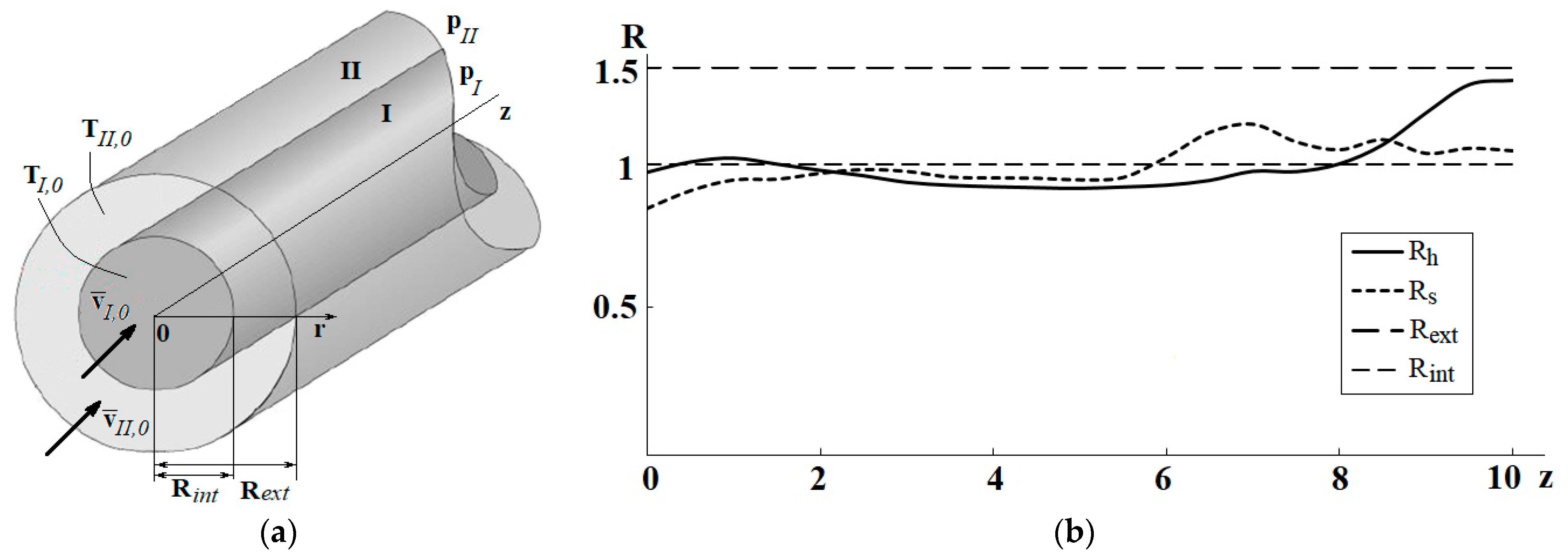
Figure 2.
Chosen geometry of the reactor (internal tube) and its cooling system (external tube): (a) Geom1 (base case reactor); (b) Geom2; (c) Geom3; (d) Geom4; (e) Geom5; (f) Geom6; (g) Geom7; (h) Geom8; (i) Geom9.
Figure 2.
Chosen geometry of the reactor (internal tube) and its cooling system (external tube): (a) Geom1 (base case reactor); (b) Geom2; (c) Geom3; (d) Geom4; (e) Geom5; (f) Geom6; (g) Geom7; (h) Geom8; (i) Geom9.
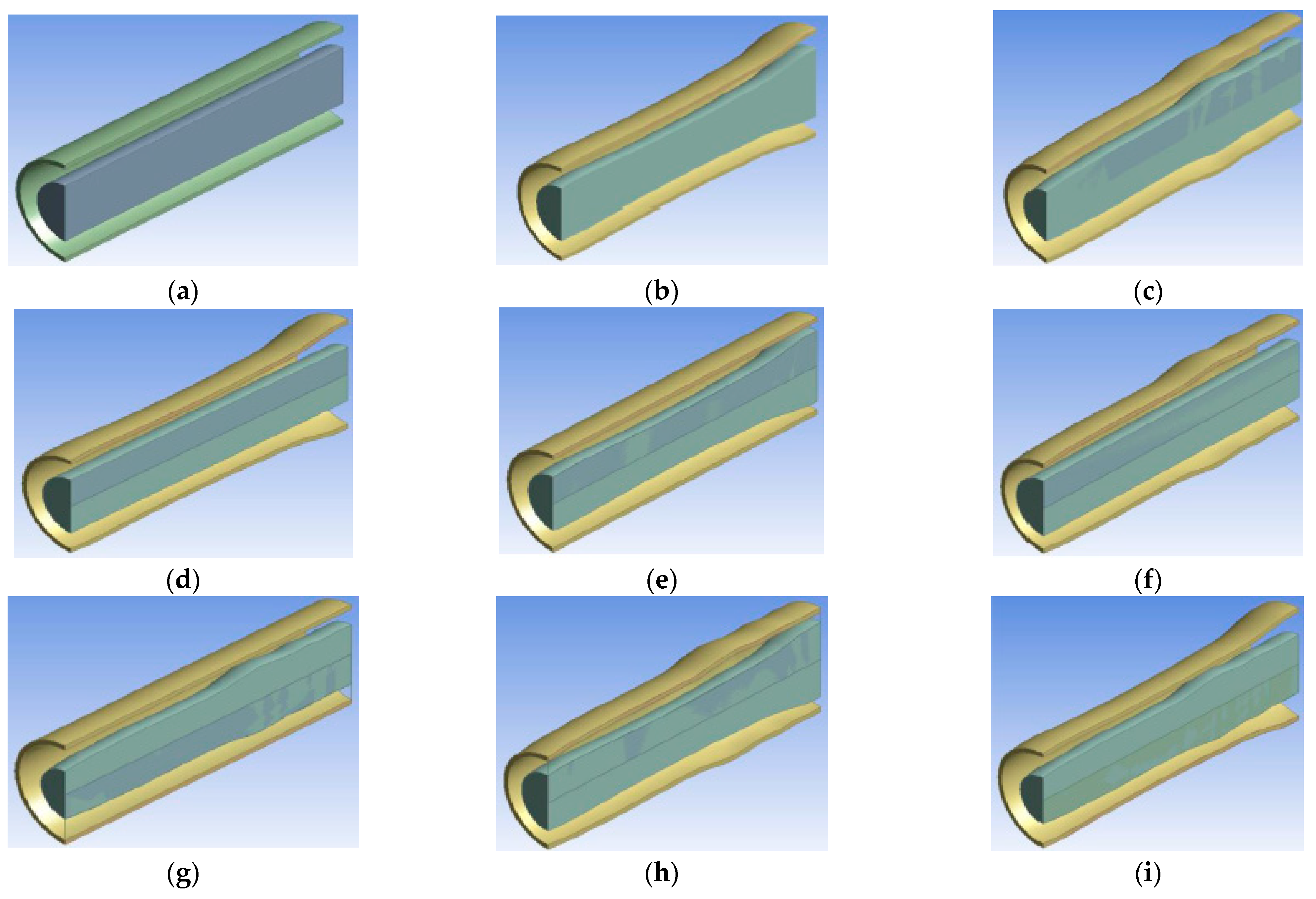
Figure 3.
Refined uniform mesh for the geometry pictured in Figure 2b.
Figure 3.
Refined uniform mesh for the geometry pictured in Figure 2b.
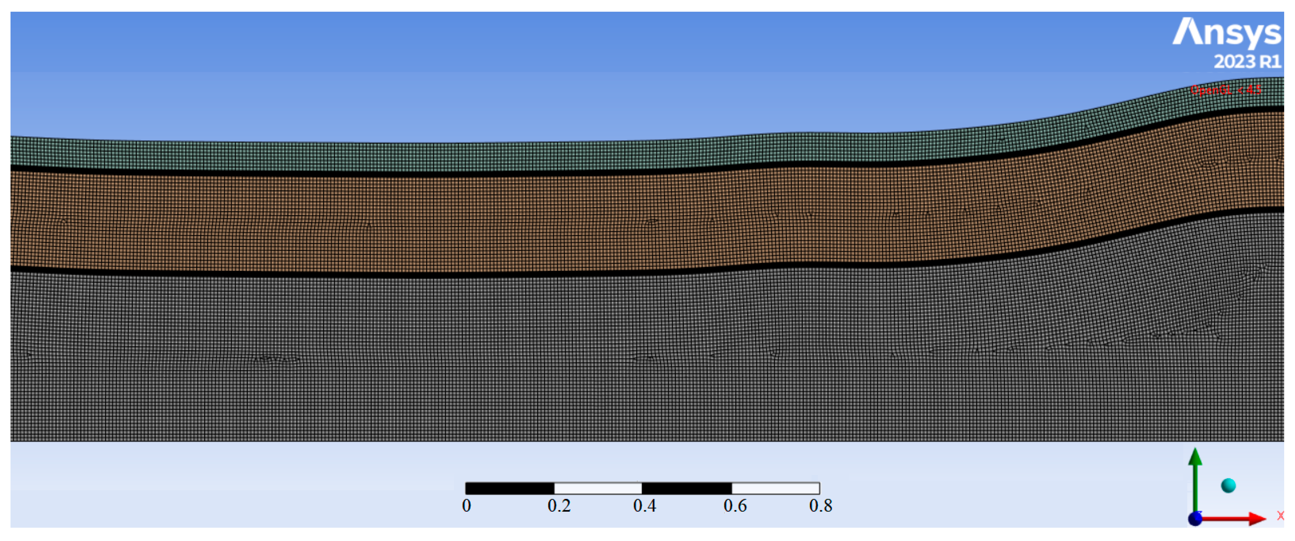
Figure 4.
Contour plots of the temperature distributions in the basic case reactor: (a) inside the reactor; (b) 3D in the reactor and cooler; (c) 2D in the cooler with short Lth; (d) 2D in the cooler with long Lth.
Figure 4.
Contour plots of the temperature distributions in the basic case reactor: (a) inside the reactor; (b) 3D in the reactor and cooler; (c) 2D in the cooler with short Lth; (d) 2D in the cooler with long Lth.
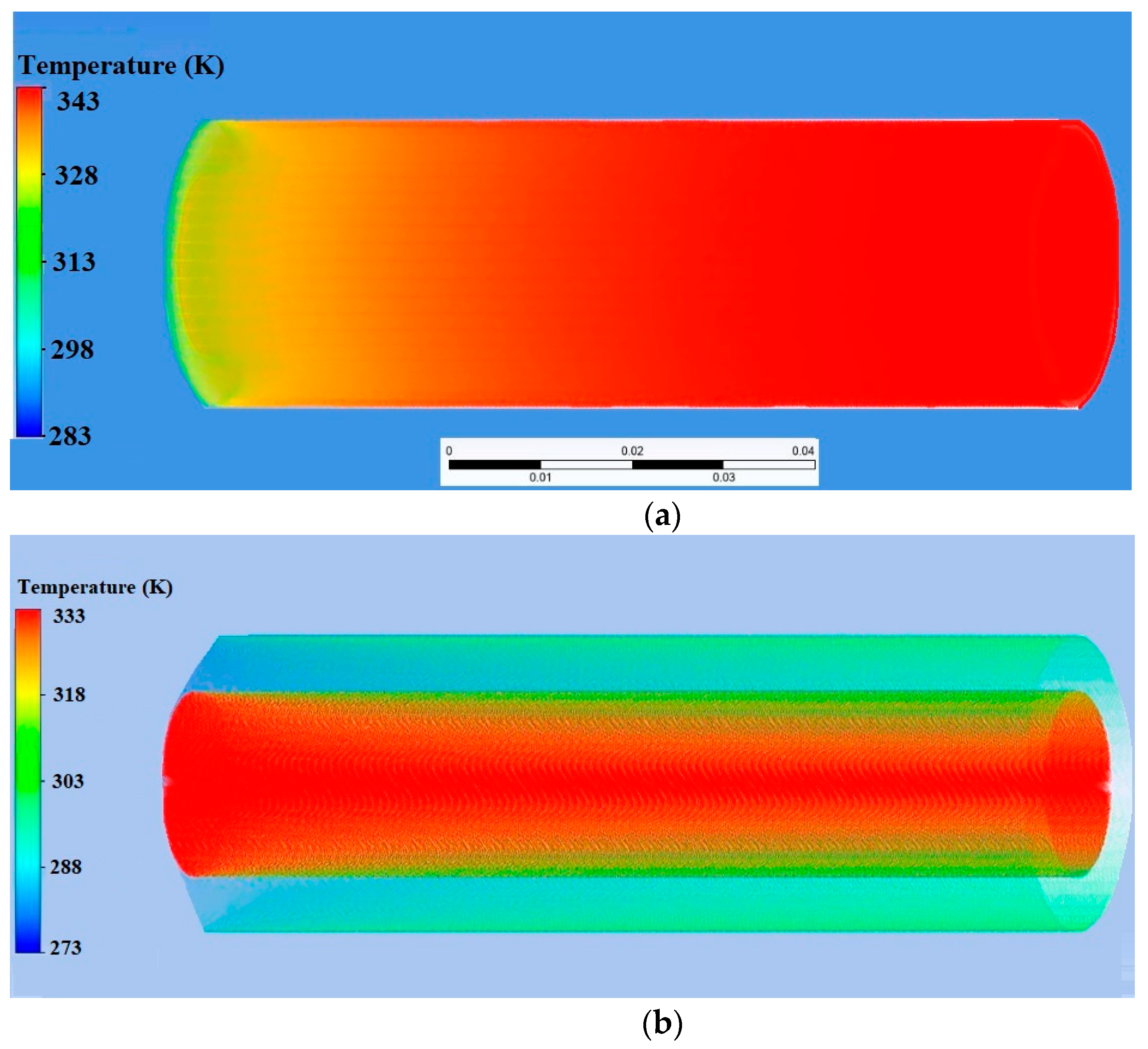

Figure 5.
Pareto frontiers for the optimal problem solution (1) in (14): (a) best geometries; (b) flow patterns in the best geometries.
Figure 5.
Pareto frontiers for the optimal problem solution (1) in (14): (a) best geometries; (b) flow patterns in the best geometries.
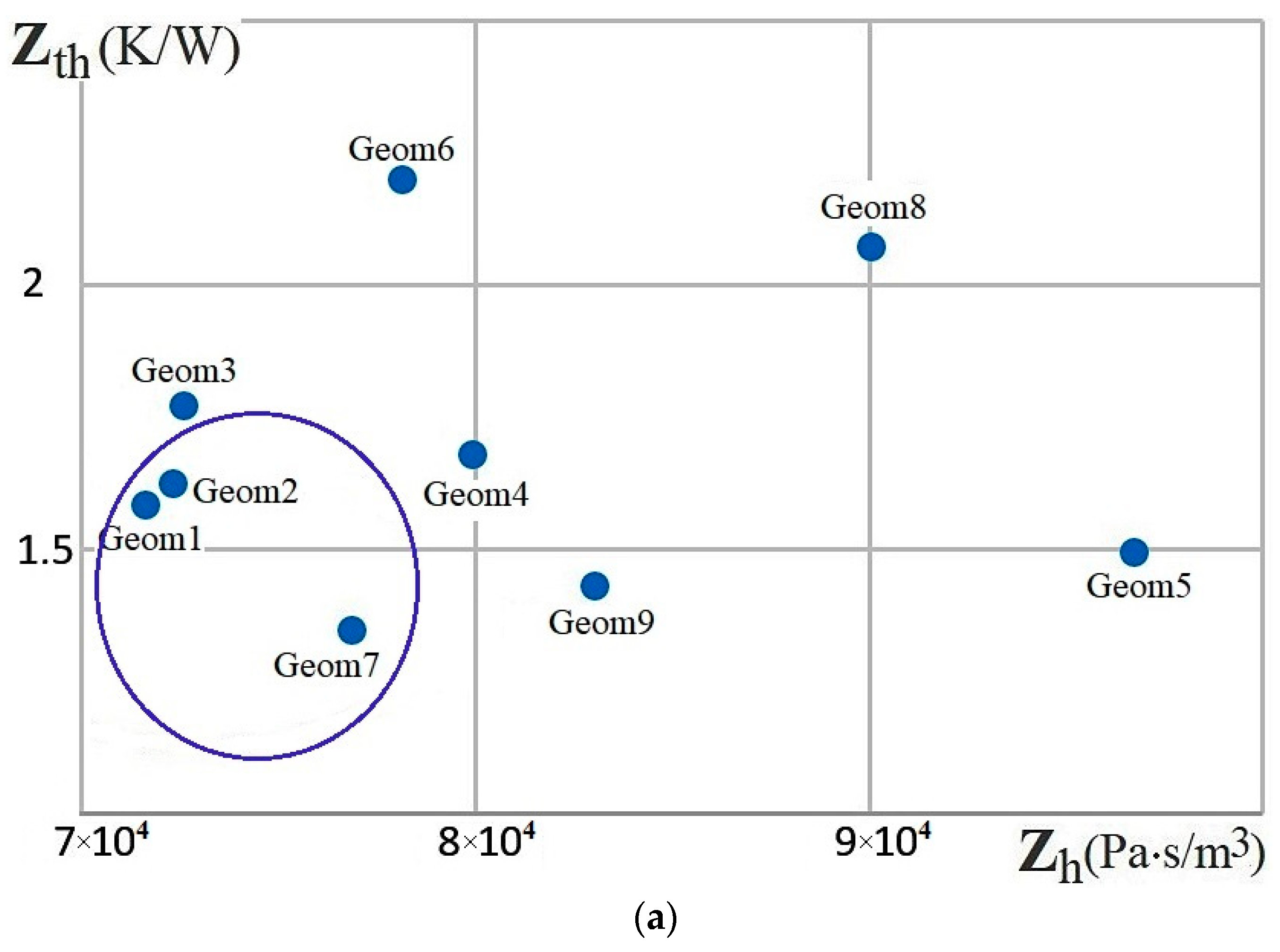
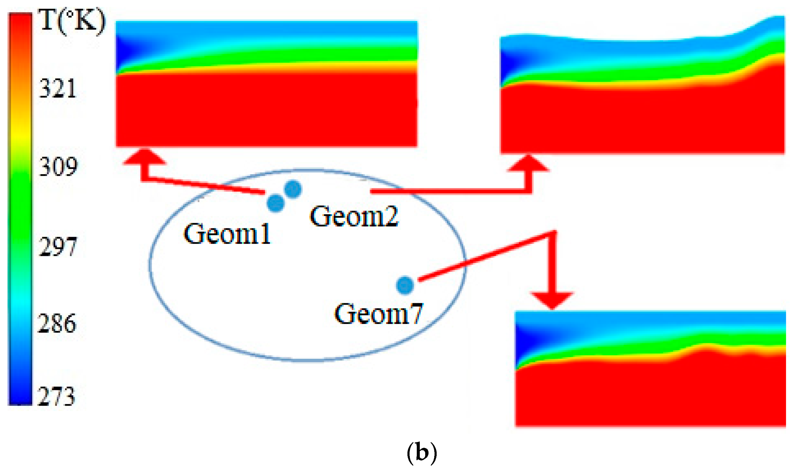
Figure 6.
Pareto frontiers for the optimal problem solution (2) in (14): (a) best geometries; (b) flow patterns in the best geometries (the temperature scale is the same as in Figure 5b).
Figure 6.
Pareto frontiers for the optimal problem solution (2) in (14): (a) best geometries; (b) flow patterns in the best geometries (the temperature scale is the same as in Figure 5b).
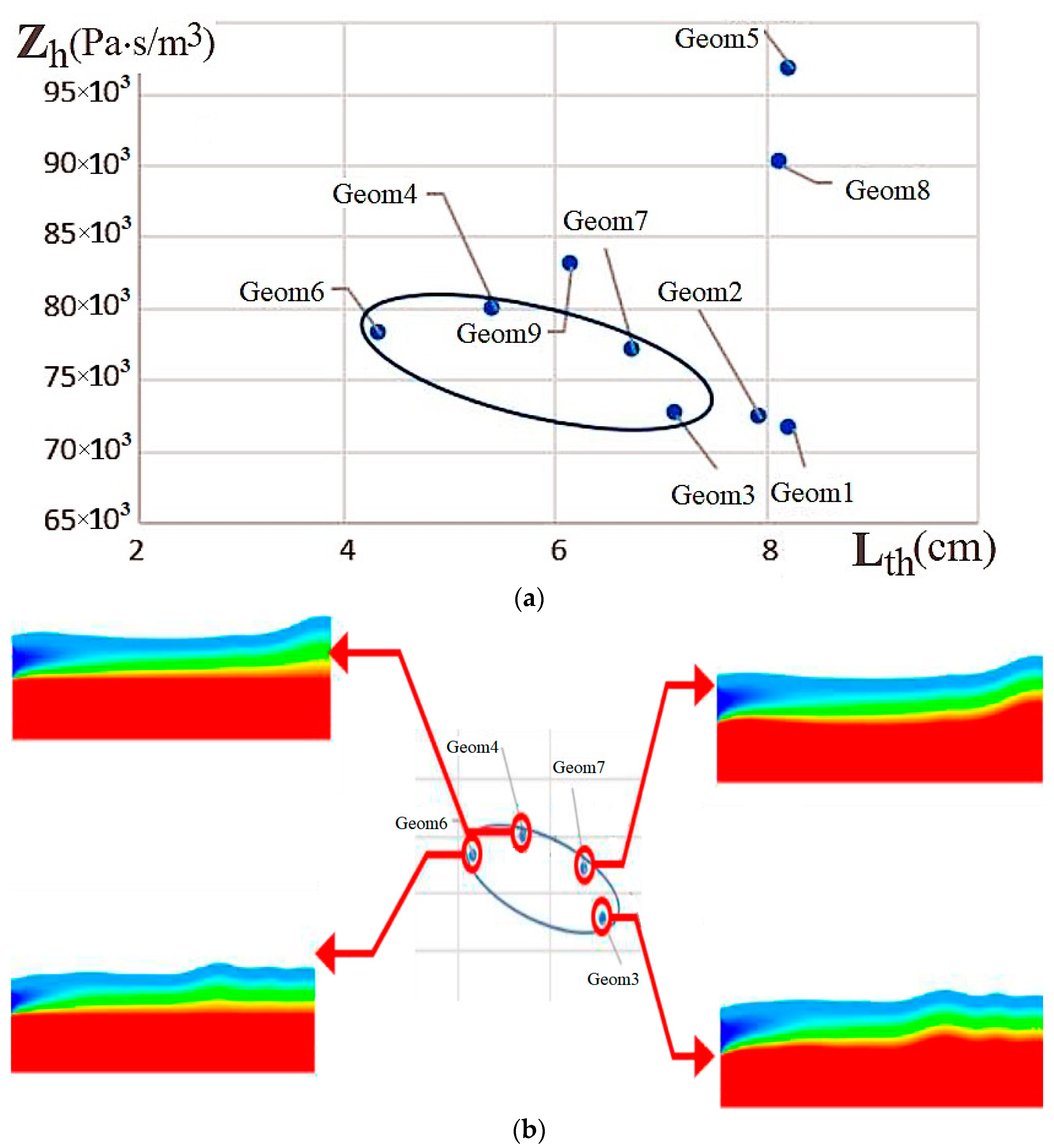
Figure 7.
Pareto frontiers for the optimal problem solution (3) in (14): (a) best geometries; (b) flow patterns in the best geometries (the temperature scale is the same as in Figure 5b).
Figure 7.
Pareto frontiers for the optimal problem solution (3) in (14): (a) best geometries; (b) flow patterns in the best geometries (the temperature scale is the same as in Figure 5b).
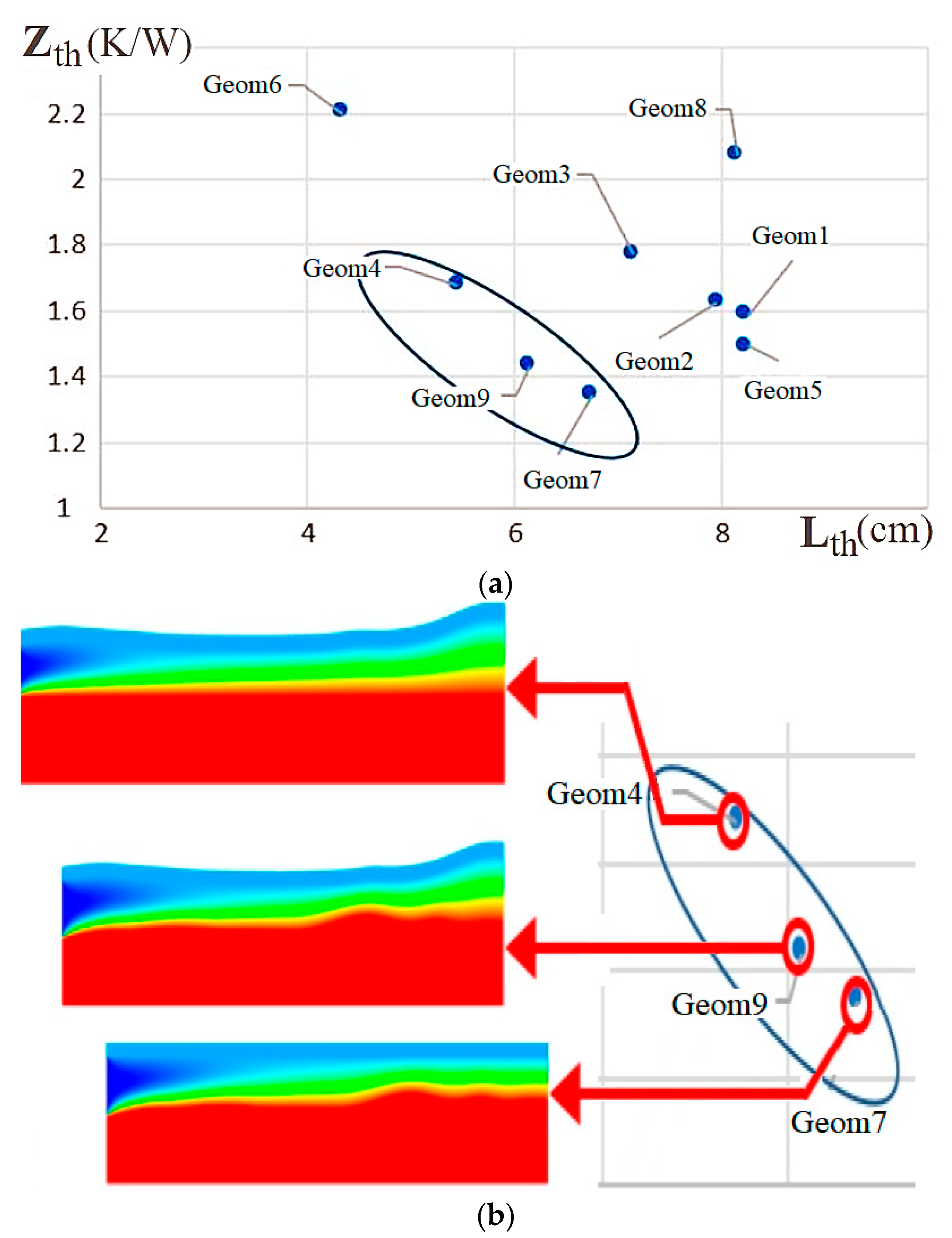
Figure 8.
Pareto frontiers for the pair (,) of objective functions: (a) best geometries; (b) flow patterns in the best geometries (the temperature scale is the same as in Figure 5b).
Figure 8.
Pareto frontiers for the pair (,) of objective functions: (a) best geometries; (b) flow patterns in the best geometries (the temperature scale is the same as in Figure 5b).
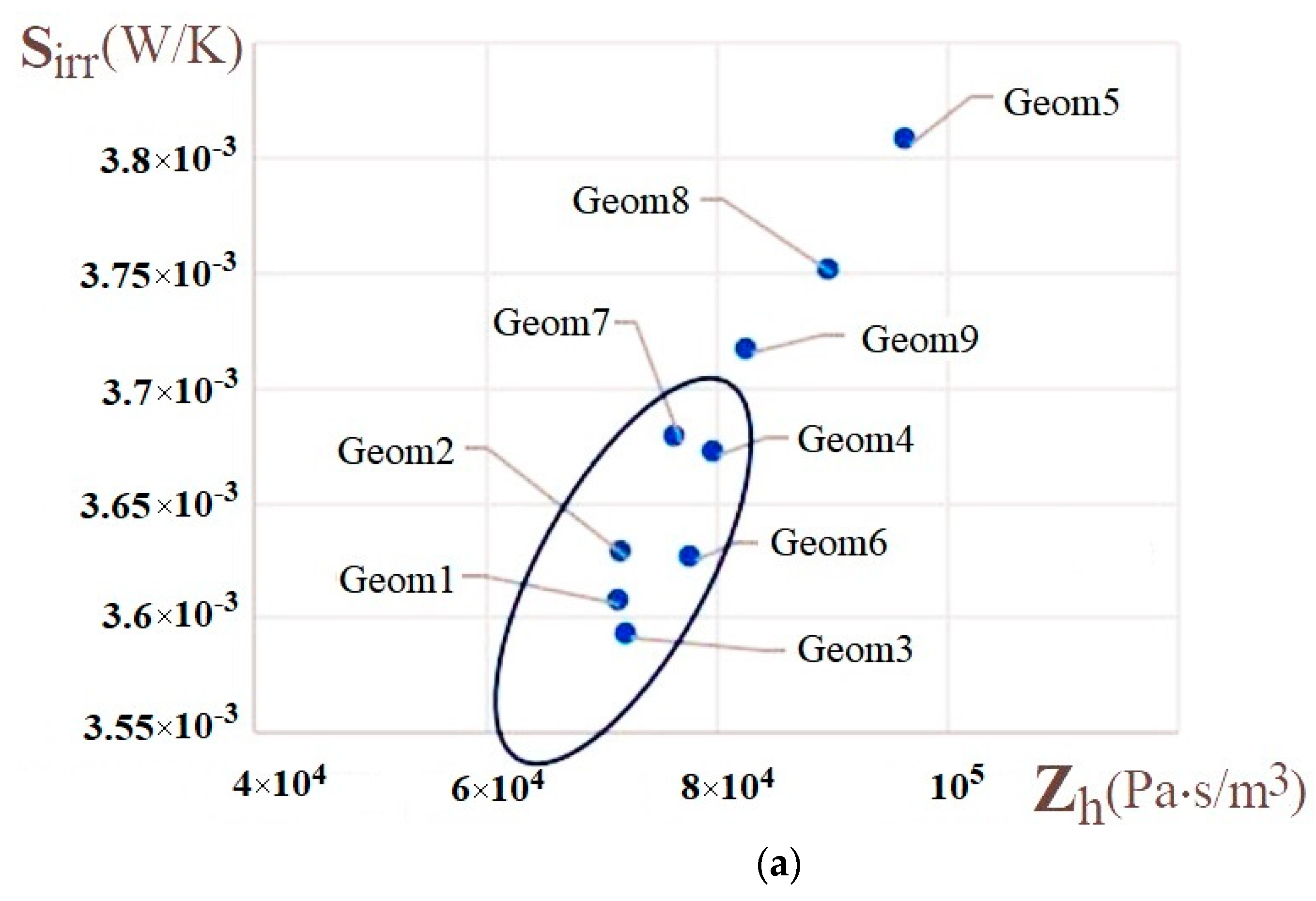
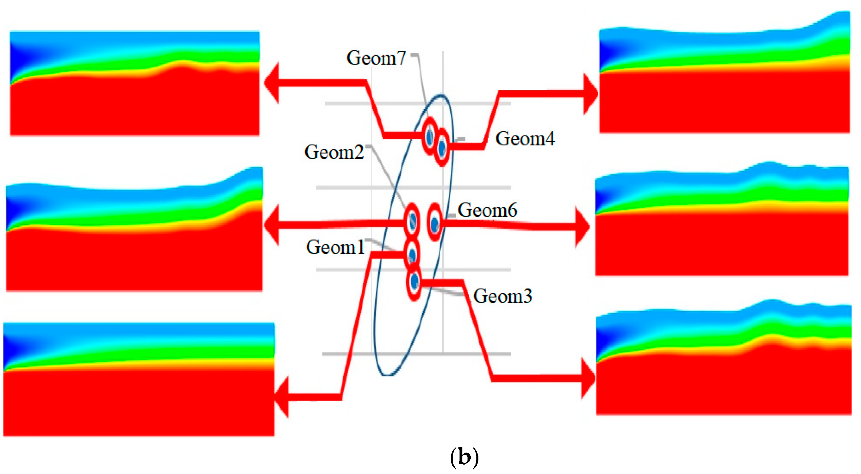
Figure 9.
Pareto frontiers for the pair (,) of objective functions: (a) best geometries; (b) flow patterns in the best geometries (the temperature scale is the same as in Figure 5b).
Figure 9.
Pareto frontiers for the pair (,) of objective functions: (a) best geometries; (b) flow patterns in the best geometries (the temperature scale is the same as in Figure 5b).
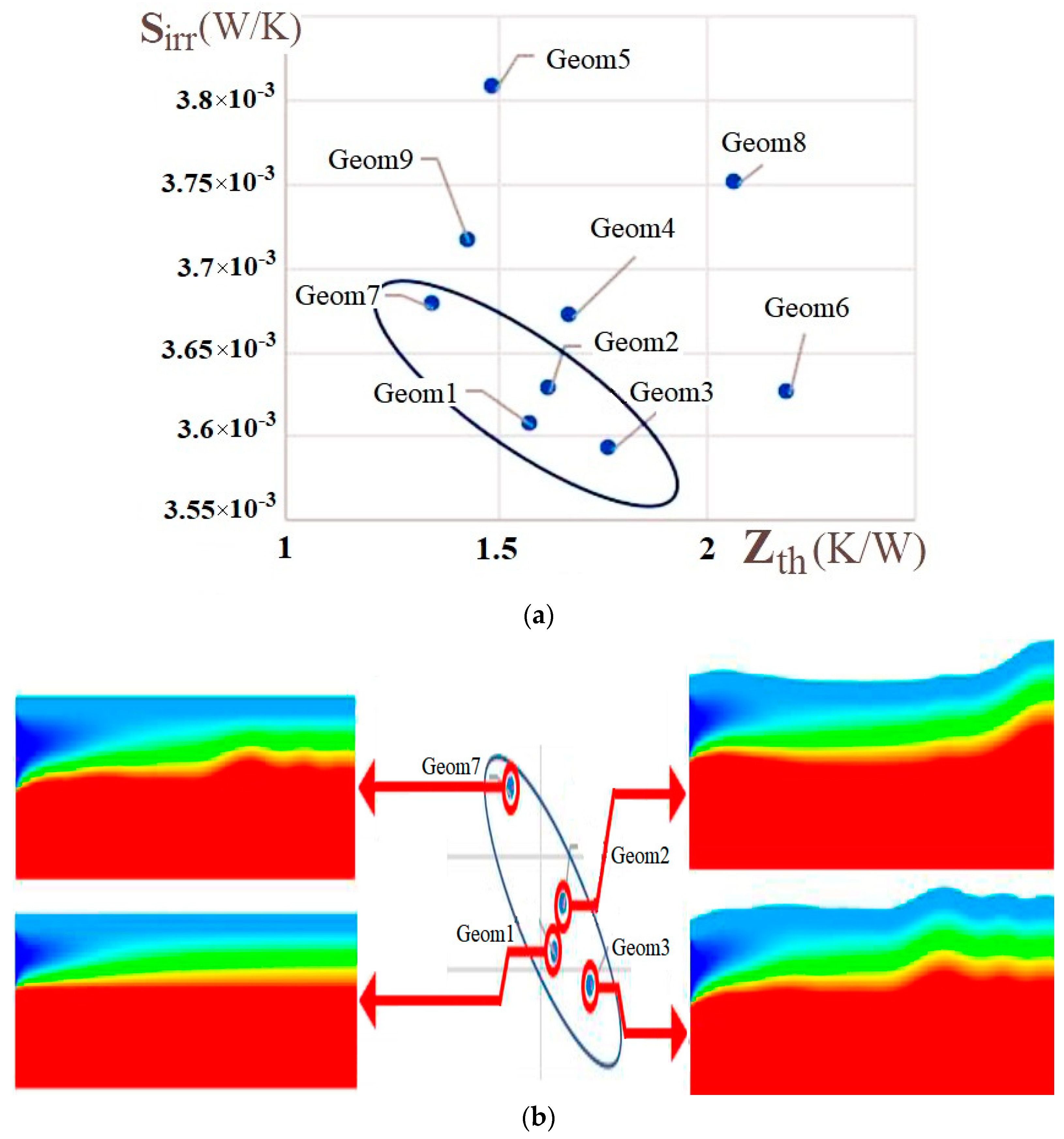
Figure 10.
Distributions in different geometries: (a) entropy production ; (b) coolant temperature Tc(z).
Figure 10.
Distributions in different geometries: (a) entropy production ; (b) coolant temperature Tc(z).


Table 1.
Geometric details for non-dimensional radii of the internal and external tubes in the system.
Table 1.
Geometric details for non-dimensional radii of the internal and external tubes in the system.
| Name | Rint | Rext | Image |
|---|---|---|---|
| Geom1 (base case reactor) | 1 | 1.5 | Figure 2a |
| Geom2 | Rh(z) scaled to 1 | Rh(z) scaled to 1.5 | Figure 2b |
| Geom3 | Rs(z) scaled to 1 | Rs(z) scaled to 1.5 | Figure 2c |
| Geom4 | 1 | Rh(z) scaled to 1.5 | Figure 2d |
| Geom5 | Rh(z) scaled to 1 | 1.5 | Figure 2e |
| Geom6 | 1 | Rs(z) scaled to 1.5 | Figure 2f |
| Geom7 | Rs(z) scaled to 1 | 1.5 | Figure 2g |
| Geom8 | Rh(z) scaled to 1 | Rs(z) scaled to 1.5 | Figure 2h |
| Geom9 | Rs(z) scaled to 1 | Rh(z) scaled to 1.5 | Figure 2i |
Table 2.
Best geometry as numbered in the case list, according to the pairs of objective functions.
| - | 1, 2, 7 | 3, 4, 6, 7 | 1, 3 | |
| - | 4, 7, 9 | 1, 2, 3, 7 | ||
| - | 6 |
Disclaimer/Publisher’s Note: The statements, opinions and data contained in all publications are solely those of the individual author(s) and contributor(s) and not of MDPI and/or the editor(s). MDPI and/or the editor(s) disclaim responsibility for any injury to people or property resulting from any ideas, methods, instructions or products referred to in the content. |
© 2024 by the authors. Licensee MDPI, Basel, Switzerland. This article is an open access article distributed under the terms and conditions of the Creative Commons Attribution (CC BY) license (https://creativecommons.org/licenses/by/4.0/).
Share and Cite
MDPI and ACS Style
Kizilova, N.; Shankar, A.; Kjelstrup, S. A Minimum Entropy Production Approach to Optimization of Tubular Chemical Reactors with Nature-Inspired Design. Energies 2024, 17, 432. https://doi.org/10.3390/en17020432
AMA Style
Kizilova N, Shankar A, Kjelstrup S. A Minimum Entropy Production Approach to Optimization of Tubular Chemical Reactors with Nature-Inspired Design. Energies. 2024; 17(2):432. https://doi.org/10.3390/en17020432
Chicago/Turabian StyleKizilova, Natalya, Akash Shankar, and Signe Kjelstrup. 2024. "A Minimum Entropy Production Approach to Optimization of Tubular Chemical Reactors with Nature-Inspired Design" Energies 17, no. 2: 432. https://doi.org/10.3390/en17020432
Note that from the first issue of 2016, this journal uses article numbers instead of page numbers. See further details here.