
Comprehensive Modulation Strategies for Synchronous Reluctance Motor Drives Used in Weak Grids
by
 , , ,
, , ,
Shuo Wang
1,
Dmytro Prystupa
1,
Yuli Bao
1,*,
Vasyl Varvolik
1,
Giampaolo Buticchi
1,
He Zhang
1 and
Michele Degano
2 1
Key Laboratory of More Electric Aircraft Technology of Zhejiang Province, The University of Nottingham, Ningbo China, 199 Taikang East Road, Ningbo 315100, China
2
PEMC Group, University of Nottingham, Nottingham NG7 2RD, UK
*
Author to whom correspondence should be addressed.
Energies 2024, 17(3), 615; https://doi.org/10.3390/en17030615
Submission received: 25 November 2023
/
Revised: 12 December 2023
/
Accepted: 19 December 2023
/
Published: 26 January 2024
(This article belongs to the Topic Energy Management and Efficiency in Electric Motors, Drives, Power Converters and Related Systems)
Abstract
:Synchronous reluctance machines are considered a cost-effective solution for several industrial applications and present potential efficiency benefits compared to induction motors. In industrial applications, power supply oscillations can lead to short-term disturbances that can affect the drive operation; therefore, the control must be robust to guarantee high efficiency and service continuity. The focus of this study was to identify the speed boundaries considering different values of applied DC-link voltage, taking into account the highly nonlinear magnetic behavior of the machine and its cross-coupling characteristics. In addition, a comprehensive carrier-based implementation of a pulse width modulation strategy was proposed to achieve optimal efficiency in both the machine and converter, which is essential in the presence of “weak” grids. The proposed technique was demonstrated to meet the desired reference torque and rated speed, even during DC-link voltage drops (up to 7.4% of the rated voltage). The proposed methodology was experimentally validated on a 90 kW SynRM drive with a broader modulation range and higher efficiency. This work considered several different supply voltage levels to assess the stability and continuity of torque output and further proved the proposed method.
1. Introduction
Synchronous reluctance machines (SynRM) are potential candidates for replacing induction motors in many industrial applications such as pumps, fans, and extruders. One of the main reasons for using SynRM is its low cost and high efficiency. These machines are supplied by a variable-frequency drive, typically a three-phase voltage source inverter (VSI). However, direct-current link (DC-link) voltage utilization (DCVU) is sometimes insufficient [1,2,3,4], mainly when the motor is operating at a rated speed and rated load. The critical reasons for this can be identified as follows: (a) factories located in remote areas may experience voltage dips when connected to weak grids [1,2], (b) DC-link capacitances are usually designed to be a compromise to meet drive volume and cost targets [3,4] but they are insufficient to cope with high supply variations, and (c) the effective induced back electromotive force of motors is designed to be close to the available voltage. In these cases, a disturbance from the load or grid fluctuation can cause sudden software trips and significantly affect manufacturing processes sensitive to variations in motor operating speed.
Maintaining a stable desired torque and speed is very important, and this needs to be guaranteed even in the case of poor grid stability (i.e., 5–6% of the maximum DC-link voltage fluctuation, which is reported and discussed in [1,2]). In addition, this should be achieved without an excessive oversizing of DC-link capacitors [3,4]. When the converter and motor for a specific application cannot be upgraded or redesigned, one way to compensate and achieve stability is to develop advanced control algorithms. The approaches in the literature can be divided into two main categories: changing suitable modulation strategy and selecting the motor’s optimal operating point.
On the one hand, researchers are attempting to fully utilize inverters by changing the pulse width modulation (PWM). Space vector PWM (SVPWM) is the most common modulation method adopted in the industry, where the maximum peak output phase voltage can reach 0.577 times the DC-link voltage [5,6]. A VSI can be operated in the overmodulation region to obtain higher fundamental voltage values until the six-step operation state [5,6,7,8,9]. In [5,6,7], the overmodulation region was divided into mode I, mode II, and six-step mode. In overmodulation mode I, the voltage reference is located between the voltage hexagon-inscribed circle and the boundary of the voltage hexagon. In overmodulation II, the voltage reference vector exceeds the side of the hexagon, and the maximum actual output voltage is held at a vertex for a particular time and then moved along the side of the hexagon for the remainder of the switching period. In the six-step operation mode, the voltage vectors can only move at the six vertices of the hexagon, as discussed in [8,9]. Other works have presented different discontinuous PWM (DPWM) strategies [10,11,12,13,14] that can be implemented by properly injecting zero-sequence voltage into the original modulation waveform. The modulation voltage waveform of one phase has one segment each of 120° (DPWMmax, DPWMmin), 60° (DPWM0, DPWM1, DPWM2), or 30° (DPWM3) clamped to the positive or negative DC-link voltage during which no switching occurs in either inverter arm. Therefore, the six classic DPWM schemes have lower switching losses than continuous PWM (CPWM) schemes. The mathematical relationship between DPWM and overmodulation was derived in [15,16,17,18]. The generalized DPWM method was proposed in [10,11,12] to unify DPWM0, DPWM1, and DPWM2 with the phase-shift angle φ. The phase shift was selected to be fixed at −30°, 0°, and 30° in [10,18]. Also, the split-clamp DPWM can be found in [19,20,21,22,23] and implemented by applying a timing sequence such as ‘0127’, ‘012’, ‘721’, ‘0121’, or ‘7212’. The 60° clamping regions can be considered as two sub-clamping regions. Further switching loss reduction can be achieved at a power factor angle higher than 60° compared with the six classic DPWM schemes. Modifications to DPWM have been proposed in the literature [24,25] to achieve different optimization targets, including common-mode reduction PWM (CMVRPWM) and switching-loss optimized CMVRPWM in [24], and hybrid PWM in [25]. However, the entire power factor angle range [0, π/2] lacks analysis for a specific machine.
On the other hand, researchers have selected the optimal current setpoints for a motor to achieve a low-voltage operating mode [1,26,27]. In particular, when a motor operates at a rated speed and load, the control margin is limited to deal with the DC-link voltage drop. In [1], the authors evaluated the allowable voltage according to the operating point and attempted to use a higher current to maintain the same reference torque. In [28], several cases were studied in which a compressor motor was connected to a weak grid. In [26,27,28,29], the authors used numerical and analytical methods to determine the optimal current operating points by analyzing the relationship among the torque, speed, voltage, and current constraints. However, the main drawback was that the copper loss increased, and the motor efficiency was not guaranteed.
Considering the abovementioned state-of-the-art techniques and literature, a theory that combines both the operating principle of nonlinear SynRMs and the full DCVU on a VSI with different modulation strategies has not yet been presented.
The main contributions of this study are as follows:
- (a)
- A carrier-based power-factor adaptive PWM (PFA-DPWM) implementation was proposed to improve motor and drive efficiency;
- (b)
- The speed/torque limits for different DC-link voltages considering the nonlinear cross-coupled mode were comprehensively evaluated;
- (c)
- The optimal appropriate modulation strategies for a specific SynRM were selected.
The remainder of this paper is organized as follows. In Section 2, the control margin of both current and voltage constraints is derived, and voltage utilization issues are discussed. In Section 3, a comprehensive modulation is proposed, and the harmonics, switching losses, and DCVU are evaluated. The experimental results validating the proposed method are presented in Section 4, and the conclusions are presented in Section 5.
2. Voltage Utilization Issue Statement on Specific SynRMs
2.1. SynRM Modeling
A four-pole, 90 kW SynRM was considered for the case study. The SynRM equivalent circuit can be shown in Figure 1a,b [30,31,32]. The equations describing the operation of the SynRM can be written as follows [9,13,29]:
where ud and uq are the dq-axis stator voltages, ψd and ψq are the dq-axis flux linkages including the magnetic saturation and cross-saturation as shown in Figure 1c,d, id and iq are the dq-axis current components, and Ld and Lq are the inductances along the d- and q-axes, respectively. Rs and p are the stator resistance and pole pair, respectively, and ωe is the electrical angular speed of the motor.
The torque equation can be described as
Two additional constraints must be considered [26,27,29,30]. The first is related to the motor or inverter current limit (4). The other factor is related to the voltage limit (5).
Vmax is related to the maximum available voltage from the DC link. The voltage (1) can be expressed in the steady state as
The key data of the SynRM considered are listed in Table 1. When the SynRM reached its rated operating point at 1500 rpm, the phase voltages were designed to be approximately 210 V-RMS. DC-link voltage should be designed to be higher than 514 V in order to guarantee control margin, as discussed in [6,8].
In most torque control applications, accurate dq-axis flux linkages ψd(id,iq) and ψq(id,iq) are required for torque estimation and optimal current setpoint selection. In particular, for the SynRM, because of the flux magnetic saturation and cross-saturation effects in Figure 1a,b,the flux-linkages are nonlinear as a current function (600 A is selected, considering overload conditions). Look-up tables (LUTs) are still the most adopted solution in industrial drive applications [26,27] because of their simplicity of implementation and low computational requirements (only flash memory space is required). For clarity, in the following, one current setpoint (id,iq) was mapped to a specific dq-axis flux linkage (or dq-axis inductance using Equation (2)).
2.2. Speed Limit at Specific DC-Link Voltage
As shown in Figure 2, the current limit trajectory in Equation (4) in the dq-axis current plane formed a current circle centered at the origin with radius Imax,pk. There are various control strategies proposed as hysteresis current control [35,36,37,38] or dual-voltage-vector model-free predictive current control—DVV-MFPCC [39,40]. A modulation strategy is required to coordinate with the voltage vector generation. In the SVPWM mode, Vmax was chosen as Vdc/ [6,8]. The voltage constraint of Equation (7) describes a series of voltage ellipses shrinking with increasing speed in the dq-axis current plane. The solid red line represents the MTPA curve, and the rated torque in the MTPA curve is highlighted as a red point (Table 1: 573 Nm). The iso–torque curves are represented by hyperbolas with a step of 100 N.m from Equation (3).
Equation (7) can be rewritten as quadratic Equation (8), where Equation (9) represents the coefficients of Equation (8). If the DC-link voltage is sampled, one dq-axis current point can be mapped to a limited speed in Equation (10) by solving Equation (9).
As shown in Figure 2, at 1500 rpm, assuming that Vmax is chosen as Vdc/, the dashed line on the left is depicted as a voltage ellipse with a 510 V DC-link voltage, while the solid line on the right represents the voltage at a 540 V DC-link voltage. When the DC-link voltage was 510 V, the maximum torque on the MTPA curve was close to 400 Nm. In this case, if the DC-link voltage drops from 540 V to 510 V, the rated red point of the MTPA falls out of the voltage constraint, and the drive may generate a software trip or lose control.
The maximum speed using the available DCVU is essential for guaranteeing the stability and reliability of a controller. The main influential factors that can cause the DCVU of an inverter to be insufficient are summarized below:
- (a)
- The input voltage can drop because of a weak grid, and a 5–6% input ripple voltage exists when connected to a weak grid, as mentioned in [2].
- (b)
- Considering the volume and cost, the drive size is usually designed to be highly compact and leads to a limited capacitor volume. In our case, the DC-link voltage was connected in parallel with four electrolytic capacitors (two in series and then in parallel, 8200 µF/400 V × 4; 8200 µF in total), as shown in Figure 3. The DC-link voltage may drop when the output mechanical power increases as discussed in [3].
- (c)
- The induced voltage for the SynRM was designed to be close to the available DC-link voltage; for example, the phase voltages, in our case, were intended to be approximately 210 V-RMS.
However, these factors do not occur simultaneously, and evaluating them in practical applications is challenging. For the above reasons, in the analysis and experiments presented in the following sections, the DC-link voltage cases are mainly divided into two levels: (a) expected voltage drop level—low voltage ranges from 500 V to 550 V, covering all factors to provide a sizeable DC-link voltage drop of approximately 7.4%—and (b) extreme voltage drop level—the worst DC-link voltage range considered was approximately 450 V–500 V for super-weak grid analysis.
3. Proposed Comprehensive Modulation Strategy Used for SynRMs
A typical grid-connected variable-frequency SynRM drive inverter structure is shown in Figure 3. The three-phase input voltage passes through six diodes acting as a rectifier to set up the DC-link voltage. The DC-link voltage is then converted to an alternating current to apply a three-phase set of voltages at the motor terminals. The parameters used are listed in Table 2. The system’s overall efficiency can be divided into machine and inverter efficiencies. Considering that the machine efficiency is fixed by the prototype behavior and that the conducting loss of the inverter depends on the load current, further improvement of the overall efficiency can only be achieved by reducing the switching losses of the inverter.
The well-known DPWM method is a possible solution when used in a high-modulation index field to reduce the switching times with one phase clamped to the DC-link bus. As explained in [10,11,12,13,14], according to the segment period for discontinuous modulation, DPWM can be divided into six classic types: 120° clamping (DPWMmax and DPWMmin), 60° clamping (DPWM0, DPWM1, and DPWM2), or 30° clamping (DPWM3). Some studies [19,20,21,22,23] discussed advanced clamping DPWM (split-clamp DPWM), in which the 60° clamping region is divided into two sub-clamping regions from DPWM0–2. The DPWM3 can be regarded as a particular case of split-clamp DPWM. The DPWM2, 10°/50° split-clamp DPWM, 20°/40° split-clamp DPWM, and DPWM3 modulation waveforms in green are shown in Figure 4a–d, respectively.
Different types of DPWM exhibit various switching losses under different power factors as explained in [19,20,21,22,23]. Before discussing the details of the implementation, the power factor can be defined from the vector diagram of the SynRM as shown in Figure 5 [33,34]. Is is the composite vector of the dq-axis current in the first quadrant, γ is the MTPA control angle calculated from the arctan (Iq/Id), and Vs is the composite vector of the dq-axis voltages. The power factor angle φ is the offset angle between voltage vector Vs and current vector Is, which can be calculated as
Id and Iq can be calculated from the classic Park and Clark transformation from three-phase current sensors, while the dq-axis voltages Vd and Vq are recalculated by the PI controller in the current loop. Because the arctangent function is highly nonlinear and discontinuous, the third-order rational fraction polynomial approximation described in [31] was used. The power factor angle can be rewritten as Equation (12). The maximum angle approximation error was approximately 0.00810°.
The power factor was experimentally captured for all ranges of operating conditions, particularly for the SynRM depicted in Figure 6. The power factor of this SynRM ranged from 0.4 to 0.79, depending on the load and speed conditions. When the modulation index is very low (e.g., no load or low-speed operation), the power factor can be even lower than 0.4.
3.1. Proposed Power Factor Adaptive Discontinuous PWM Strategy
The conventions were followed:
- (a)
- The ratio of the fundamental component magnitude of the phase output voltage to the DC-link voltage is termed the modulation index in m = Vs/(Vdc).
- (b)
- The three-phase voltage modulation signals are marked as Vx (x = a,b,c), representing (Va, Vb, Vc) with a mutual difference of 120° in Equation (13), where Ma is equal to Vs/(0.5Vdc) as the normalizing coefficient. The zero-voltage vector Vzc was superimposed on the original voltage signal, Vx (x = a,b,c), and did not influence the line-to-line voltage. Therefore, abundant control effects can be achieved by injecting different forms of sequence voltage vectors.
- (c)
- The power factor angle φ is shown in rad units, and the degree (unit) can be obtained from 180/π times rad (unit).
- (d)
- Design functions include:
sgn() is a sign function where sgn(Va) = 1 when Va ≥ 0, and sgn(Va) = 1 when Va < 0.
Middle() is the function used to find the phase at the middle values; for example, when Vb > Vc > Va, then Middle(Va, Vb, Vc) = Vc; for example, Middle(Vax, Vbx, Vcx) = Vc, when Vbx > Vcx > Vax.
Max() is the function used to find the phase at the maximum values; for example, when Vb > Vc > Va, Max(Va, Vb, Vc) = Vb:
The cases were divided by minimizing the switching losses, as further discussed in Part B.
Case II: when φ is within [π/6, π/3], the DPWM2 pattern is selected, and φ is fixed at π/6.
Vzc is the injected zero-sequence voltage vector. A zero-sequence voltage vector can added in the three-phase voltage as Equation (20).
3.2. Proposed PFA-DPWM Switching Loss Analysis
Figure 7a depicts the entire switching process for one carrier period. ton and toff represent the turn-on and turn-off time of the switching devices. The shaded part represents the switching loss. The average value of switching loss per carrier cycle over the fundamental cycle can be calculated as
For the CPWM, the switching loss can be calculated as
The DPWM switching loss analysis can be evaluated by the switching loss function (SLF) in [18,19,20,21,22,23] as
As shown in Figure 7b, considering the case of DPWM1 as an example with a lagging power factor angle π/4, the switching loss is equal to zero in the intervals [−π/6, π/6] where modulation stops because of clamping. Because of the half-wave symmetry of the voltage and current waveforms, the average conduction loss for a period of the fundamental wave of the phase a current can be obtained by integrating the half period [−π/2, π/2].
Following the above analysis, the general DPWM SLF is depicted in Figure 8 with different power factor angles applied. A single DPWM pattern cannot achieve the minimum switching loss under all power factors. The proposed PFA-DPWM in black was able to reach minimum switching losses for the entire power factor range [−π/2, π/2] as discussed in [19,20,21,22,23]. The minimum switching loss cases discussed in Part A can be listed as:
- φ ∈ [π/6, π/3] PFA-DPWM generates the DPWM2 pattern (marked as ③ in Figure 8). The switching losses were 0.5–0.567 times that of the SVPWM.
- φ ∈ [π/3, π/2] PFA-DPWM generates a split-clamp pattern (marked as ④ in Figure 8); the switching losses were 0.567–0.634 times that of the SVPWM.
- φ = π/2, the PFA-DPWM generates a DPWM3 pattern (marked as ⑤ in Figure 8). The switching losses were 0.634 times that of the SVPWM.
3.3. Proposed PFA-DPWM Harmonics and DCVU Analysis
The harmonic distortion factor (HDF) is a polynomial to evaluate THD of different switching patterns, which depends solely on the modulation index, as discussed in [18]:
Equation (27) shows the squared RMS value of the harmonic current. The HDF of different PWMs is depicted in Figure 9a,b. The figure shows the PFA-DPWM in the shadow region because the PFA-DPWM is between DPWM0 and DPWM3 according to the power factor. As shown in Figure 9a, all DPWM patterns had higher harmonics than the SVPWM at the same switching frequency. In the very low modulation index regions (below 0.2) or high modulation index regions (above 1), the DPWM showed a competitive and acceptable HDF. Since DPWM can reduce switching times by 1/3 compared with SVPWM, it is possible to increase the carrier frequency by approximately 3/2 compared with SVPWM while maintaining the same switching times. The HDF of all DPWM methods was multiplied by 3/2 from Equation (24), as depicted in Figure 9b. The DPWM exhibited lower harmonics than the SVPWM when the modulation index was higher than approximately 0.8.
The overmodulation in Figure 10a,b can be easily implemented by further increasing the modulated and injected voltages. When overmodulation occurs, the line-to-line waveform is distorted because the modulated voltage in the phase waveforms exceeds 1.0. An extra 10% voltage utilization in the overmodulation region can be achieved by the overmodulation strategy, as discussed in [5,6,7,8,9,18].
3.4. Modulation Strategy Selection for SynRM
Considering our specific SynRM, according to the DC-link voltage, power factor angle, and modulation index requirements, the modulation strategy can be flexibly selected as shown in Figure 11a,b and described in the five cases below:
Case I: Split-clamp DPWM modulation region (m < 0.15). As depicted in Figure 11b, the power factor is lower than 0.5. Because of the low-speed, high-torque operation of the motor, the inverter accounts for a large proportion of the conduction losses. Therefore, it is of great significance to reduce further switching losses. As shown in Figure 9, the split-clamp DPWM was selected because its HDF was very close to that of SVPWM. The switching losses were approximately 0.59 times that of the SVPWM, according to the SLF in Figure 8.
Case II: SVPWM modulation region (0.15 ≤ m < 1 and less than 80% load). SVPWM is selected to reduce the HDF (Figure 9) and improve the control performance of the motor. The load is not very heavy, and the HDF of SVPWM is optimal in this region.
Case III: DPWM2 modulation region (0.15 ≤ m < 1 and more than 80% load). The proposed PFA-DPWM changes to DPWM2 automatically because the power factor of the machine ranges from 0.6 to 0.8. The HDF value (Figure 9) of DPWM2 is competitive with that of SVPWM. The SLF values were half that of the SVPWM.
Case IV: DPWM2 overmodulation (OM) region (1 ≤ m ≤ 1.1). The SynRM enters the overmodulation region with the proposed PFA-DPWM mode, and when the voltage hexagon is reached, the maximum fundamental voltage Vmax approaches 2Vdc/π. In this higher modulation region, the target of the DPWM is to reduce the SLF and increase the DCVU.
Case V: DPWM2 decreasing speed (DS) region (m > 1.1). There is insufficient control margin to guarantee the DBU from the DC-link voltage. The operating point exceeds the speed limit in Equation (10). The safety factor α should limit the speed. The variable α is the ‘safety factor’ calculated in real-time and creates a control margin for DC-link voltage drop, and the reference speed will decrease as
The speed limit is obtained from Equation (10), and Vmax is chosen as 2Vdc/π to cover the overmodulation region.
The overall comprehensive modulation strategy is shown in Figure 12. Cases I, II, III, and IV were chosen to deal with a typical voltage drop (expected voltage drop level from 500 V to 540 V). Meanwhile, case V was selected as a solution for an extreme voltage drop level of 450 V to 500 V.
4. Experimental Results and Discussion
Several experimental tests are conducted to verify the effectiveness of the proposed method. The test bench consisted of a rated 90 kW target SynRM, a torque sensor (KISTLER 4503A2K0WA2B1000, range: 2000 N.m, Winterthur, Switzerland), and a 160 kW induction motor serving as the load machine as shown in Figure 13. The speed and angle of SynRM were measured using a resolver (Type:52AXU7102D, , Manufacturer: TAMAGAWA, Nagano, Japan). Digital signal processing (Type:TMS320F28377, Manufacturer: Texas Instruments, Dallas, Texas, USA) was used as the core device for the controller. An RS-485 communication cable was used to obtain real-time data from the DSP. The inverter was a three-phase IGBT power module (Type: FF600R12ME4, Manufacturer: Infineon, Neubiberg, Germany), with an internal temperature sensor NTC. The switching frequency was 5 kHz (Ts = 200 μs). The phase currents were sampled by three current sensors (LEM), the DC-link voltage was also sampled, and all entered the analog-to-digital channels of the DSP. The motor was connected to a power analyzer (Type: WT1804, Manufacturer:YOKOGAWA, Tokyo, Japan) to measure the current, voltage, power factor, drive efficiency, and motor efficiency. The current sensors were CT1000(Manufacturer:YOKOGAWA, Tokyo, Japan) with an accuracy of ±0.05% (±0.05% of reading +30 μA). The parameters of the machine and inverter are listed in Table 1 and Table 2, respectively. The safety factor was set to 0.9.
4.1. PWM Pattern Comparison
The SynRM was spinning at 1500 rpm with a rated torque of 573 N.m. The DC-link voltage was adjusted to 540 V by the transformer. The experimental data were recorded using a power analyzer. The experimental results are listed in Table 3 and depicted in Figure 14a–d. Table 3 shows that the total harmonic distortion (THD) of 2.2% in the DPWM2 mode was slightly higher than that of 1.8% in the SVPWM mode. The motor efficiency was 96.16% in the DPWM2 mode compared with 96.22% in the SVPWM mode. The inverter efficiency was 97.5% in the DPWM2 mode compared with 97% in the SVPWM mode. An amount of 0.5% is approximately a 500 W energy saving and significantly improves overall system efficiency, particularly when targeting specific IE classes. Furthermore, after 2 h of driving at a rated speed of 1500 rpm with 577 N.m load, the DPWM2 achieved 76 °C in drive, which is advantageous for drive reliability purposes. Even though the machine is at a steady state, however, there will still exist some speed ripple and torque ripple obtained from the torque sensor. In order to see clearly the average efficiency, a power analyzer is used for synchronous sampling controller efficiency and machine efficiency for approximately 20 min, as depicted in Figure 14a,b, respectively.
As shown in Figure 14c, the motor was spinning at 50 rpm with a rated load of 573 Nm. Split-clamp DPWM was used because the modulation index was lower than 0.15, and the inverter efficiency was 91.1% compared to 88.2% in the SVPWM mode; a 3% inverter efficiency improvement is equivalent to approximately a 100 W energy saving in this case.
When the DC-link voltage was changed to 500 V, as shown in Figure 14d, the standard SVPWM failed because the operating point was outside the voltage constraint, as discussed in Section II, Part B. When SVPWM was combined with the flux-weakening method, the machine efficiency decreased from 96.2% to 95.7%. However, the proposed method maintained the IE4 standard (IEC 60034-30-2:2016 [41]) efficiency with slightly increased current harmonics (blue line).
4.2. PWM Modulation Dynamical Experimental Results
Acceleration and deceleration tests were performed to test the dynamic and transition behaviors, as shown in Figure 15a,b, respectively. The DC link voltage was set to 500 V. The reference speed was changed from 1000 rpm to 1500 rpm with a rated load of 573 N.m. The speed response, dq-axis voltage, and modulation index are shown in Figure 15a,b. The modulation index changed from 0.75 to 1.05. The transition region changed from the linear modulation region, the DPWM2 modulation region, and the DPWM2 overmodulation region. The speed and voltage were smooth during the transition state. For the deceleration test, the reference speed was changed from 1500 rpm to 10 rpm with a rated load of 573 Nm. The modulation region was opposite to that of the acceleration process, and the final split-clamp DPWM mode was at 10 rpm and 573 Nm because the modulation index was less than 0.15.
The following experiment was designed to verify the dynamic performance of the proposed DPWM under sudden load conditions. The motor spin rate was 1500 rpm with approximately 230 N.m (40% rated load, modulation index of 0.4, and SVPWM modulation region). The power factor and their angle angles were 0.707 and 45°, respectively. After 5 s, the step torque was suddenly increased to 573 N.m (100% rated load, modulation index 0.94) with a power factor and power factor angle of 0.766° and 40°, respectively. The current loop reacted quickly to the sudden load. According to the dq-axis voltage value, power factor angle in Equation (12), and modulation index Vs/(1.732 × Vdc), all the experimental data in the dynamic process were uploaded to the monitor computer via RS-485 communications, as shown in Figure 16.
4.3. Modulation Patterns Dealing with Voltage Drop
Figure 17 depicts the waveforms of the three-phase current and line-to-line voltages for different DC-link voltages. Using the proposed method, the motor spun at a rated speed of 1500 rpm with a rated load of 573 Nm. In Figure 17a, when the DC-link voltage dropped to 510 V, and the modulation index increased to approximately 1, DPWM2 started to take effect. The peak current was always clamped with a power factor of about 0.77. In Figure 17b, when the DC-link voltage from the transformer changed to 480 V, the modulation index was close to 1.05. The motor started to enter the overmodulation region with a higher DCVU DPWM2 mode, and more harmonics were introduced in the current waveform.
An additional experiment was designed to test the proposed method on a dynamic weak grid. In Figure 18, the DC-link voltage dropped from 530 V to 475 V in 0.5 s. As shown in Figure 18, when the DC-link voltage was approximately 530 V and the modulation index was about 0.96, the SynRM operated in the DPWM2 mode. As shown in Figure 18b, when the DC-link voltage dropped to 500 V, the PFA-DPWM approach worked in the overmodulation region. The DC-link voltage clamping area became increasingly prominent, with a modulation index beyond 1.02. If the DC-link voltage dropped to 450 V in the extreme voltage level case with a modulation index over 1.128, then the safety factor attempted to limit the speed command to avoid tripping, as shown in Figure 18d, and the rated speed decreased to 1460 rpm.
5. Conclusions
This study proposed an optimized modulation strategy for a specific 90 kW SynRM to improve the DCVU and maximize the overall efficiency. Different DPWM patterns were evaluated using HDF, SLFs, and DCVU. The proposed comprehensive modulation automatically adjusted the DC-link voltage-clamped region according to the real-time power factor, DC-link voltage, load current, and modulation index. The modulation index of the proposed strategy can be extended by 5% with overmodulation. The proposed modulation strategy extended the region range with a 7.40% voltage dip with a 540 V DC-link voltage, ensuring the maximum speed and load without modifying the electromagnetic design of the machine or the topology of the power electronics. Meanwhile, the proposed comprehensive PWM pattern achieved a 0.5% higher converter efficiency compared with that of SVPWM. The proposed method was tested on a 90 kW SynRM drive considering different DC-link voltages from a simulated grid and proved to be an effective way to reduce switching losses and improve maximum voltage utilization.
Author Contributions
Conceptualization, S.W. and G.B.; validation, V.V., Y.B. and D.P.; experimental setup, S.W.; writing—review and editing, G.B. and H.Z.; supervision, S.W., D.P., Y.B., V.V., G.B., H.Z. and M.D. All authors have read and agreed to the published version of the manuscript.
Funding
This study was supported by the Zhejiang Basic and Commonweal Programme with project code LQ23E070002 and in part by the Ningbo Natural Science Foundation Programme under grant 2023J191.
Data Availability Statement
Data are contained within the article.
Conflicts of Interest
The authors declare no conflicts of interest.
References
- Ghosh, P.R.; Das, A.; Bhuvaneswari, G. Analysis and implementation of a new method to retain the original speed and torque of synchronous reluctance motor during sustained voltage dip. IET Electr. Power Appl. 2019, 13, 1365–1377. [Google Scholar] [CrossRef]
- Kim, J.; Jeong, I.; Lee, K.; Nam, K. Fluctuating current control method for a PMSM along constant torque contours. IEEE Trans. Power Electron. 2014, 29, 6064–6073. [Google Scholar] [CrossRef]
- Mathe, L.; Torok, L.; Wang, D.; Sera, D. Resonance reduction for AC drives with small capacitance in the DC link. IEEE Trans. Ind. Appl. 2017, 53, 3814–3820. [Google Scholar] [CrossRef]
- Ding, D.; Wang, G.; Zhao, N.; Zhang, G.; Xu, D. Enhanced Flux-Weakening Control Method for Reduced DC-Link Capacitance IPMSM Drives. IEEE Trans. Power Electron. 2018, 34, 7788–7799. [Google Scholar] [CrossRef]
- Lee, D.C.; Lee, G.M. A novel overmodulation technique for space-vector PWM inverters. IEEE Trans. Power Electron. 1998, 13, 1144–1151. [Google Scholar]
- Cong, W.; Qiwei, L. Analysis of naturally sampled space vector modulation PWM in overmodulation region. In Proceedings of the IEEE International Power Electronics and Motion Control Conference, Xi’an, China, 14–16 August 2004. [Google Scholar]
- Olarescu, N.V.; Musuroi, S.; Sorandaru, C.; Weinmann, M.; Zeh, S. Optimum current control for wide speed range operation of PMSM drive without regenerative unit utilizing PWM-VSI overmodulation. In Proceedings of the IEEE Energy Conversion Congress & Exposition (ECCE), Raleigh, NC, USA, 16–20 September 2012. [Google Scholar]
- Fang, X.; Tian, Z.; Li, H.; Yang, Z.; Lin, F.; Hillmansen, S. Current closed-loop control and field orientation analysis of an induction motor in six-step operation for railway applications. IET Power Electron. 2019, 12, 1462–1469. [Google Scholar] [CrossRef]
- Masisi, L.; Pillay, P.; Williamson, S.S. A modulation strategy for a three-level inverter synchronous reluctance motor (SynRM) drive. IEEE Trans. Ind. Appl. 2015, 52, 1874–1881. [Google Scholar] [CrossRef]
- Hava, A.M.; Kerkman, R.J. A high-performance generalized discontinuous PWM algorithm. IEEE Trans. Ind. Appl. 1998, 34, 1059–1071. [Google Scholar] [CrossRef]
- Hava, A.M.; Çetin, N.O. A Generalized Scalar PWM Approach with Easy Implementation Features for Three-Phase, Three-Wire Voltage-Source Inverters. IEEE Trans. Power Electron. 2011, 26, 1385–1395. [Google Scholar] [CrossRef]
- An, S.L.; Sun, X.D.; Zhang, Q.; Zhong, Y.R.; Ren, B.Y. Study on the Novel Generalized Discontinuous SVPWM Strategies for Three-Phase Voltage Source Inverters. IEEE Trans. Ind. Inform. 2013, 9, 781–789. [Google Scholar] [CrossRef]
- Masisi, L.; Pillay, P.; Williamson, S. Comparison of two modulation strategies for a three level inverter synchronous reluctance motor (SynRM) drive. In Proceedings of the 2014 IEEE Industry Application Society Annual Meeting, Vancouver, BC, Canada, 5–9 October 2014; IEEE: Piscataway, NJ, USA, 2014; pp. 1–7. [Google Scholar]
- Wu, Y.; Shafi, M.A.; Knight, A.M.; McMahon, R.A. Comparison of the Effects of Continuous and Discontinuous PWM Schemes on Power Losses of Voltage-Sourced Inverters for Induction Motor Drives. IEEE Trans. Power Electron. 2011, 26, 182–191. [Google Scholar] [CrossRef]
- Holtz, J.; Lotzkat, W.; Khambadkone, A.M. On continuous control of PWM inverters in the overmodulation range including six-step. IEEE Trans. Power Electron. 1993, 8, 546–553. [Google Scholar] [CrossRef]
- Zhou, K.; Wang, D. Relationship between space-vector modulation and three-phase carrier-based PWM: A comprehensive analysis. IEEE Trans. Ind. Electron. 2002, 49, 186–196. [Google Scholar] [CrossRef]
- Park, H.J.; Youn, M.J. A new time-domain discontinuous space-vector PWM technique in overmodulation region. IEEE Trans. Ind. Electron. 2003, 50, 349–355. [Google Scholar] [CrossRef]
- Holmes, D.G.; Lipo, T.A. Pulse Width Modulation for Power Converters: Principles and Practice; Wiley-IEEE Press: Hoboken, NJ, USA, 2003. [Google Scholar]
- Narayanan, G.; Krishnamurthy, H.K.; Zhao, D.; Ayyanar, R. Advanced bus-clamping PWM techniques based on space vector approach. IEEE Trans. Power Electron. 2006, 21, 974–984. [Google Scholar] [CrossRef]
- Nguyen, T.D.; Hobraiche, J.; Patin, N.; Friedrich, G.; Vilain, J.-P. A direct digital technique implementation of general discontinuous pulse width modulation strategy. IEEE Trans. Ind. Electron. 2010, 58, 4445–4454. [Google Scholar] [CrossRef]
- Zhao, D.; Hari, V.S.S.P.K.; Narayanan, G.; Ayyanar, R. Space-vector-based hybrid pulsewidth modulation techniques for reduced harmonic distortion and switching loss. IEEE Trans. Power Electron. 2009, 25, 760–774. [Google Scholar] [CrossRef]
- Biswas, J.; Nair, M.D.; Gopinath, V.; Barai, M. An optimized hybrid SVPWM strategy based on multiple division of active vector time (MDAVT). IEEE Trans. Power Electron. 2016, 32, 4607–4618. [Google Scholar] [CrossRef]
- Hari, V.S.S.P.K.; Narayanan, G. Theoretical and experimental evaluation of pulsating torque produced by induction motor drives controlled with advanced bus-clamping pulsewidth modulation. IEEE Trans. Ind. Electron. 2015, 63, 1404–1413. [Google Scholar] [CrossRef]
- Wu, X.; Tan, G.; Ye, Z.; Liu, Y.; Xu, S. Optimized common-mode voltage reduction PWM for three-phase voltage-source inverters. IEEE Trans. Power Electron. 2015, 31, 2959–2969. [Google Scholar] [CrossRef]
- Da Silva, E.R.C.; dos Santos, E.C.; Jacobina, B. Pulsewidth modulation strategies. IEEE Ind. Electron. Mag. 2011, 5, 37–45. [Google Scholar] [CrossRef]
- Wang, S.; Kang, J.; Degano, M.; Galassini, A.; Gerada, C. An Accurate Wide-speed Range Control Method of IPMSM Considering Resistive Voltage Drop and Magnetic Saturation. IEEE Trans. Ind. Electron. 2019, 67, 2630–2641. [Google Scholar] [CrossRef]
- Wang, S.; Degano, M.; Kang, J.; Galassini, A.; Gerada, C. A novel Newton-Raphson-based searching method for the MTPA control of PMaSynRM considering magnetic and cross saturation. In Proceedings of the 2018 XIII International Conference on Electrical Machines (ICEM), Alexandroupoli, Greece, 3–6 September 2018; pp. 1360–1366. [Google Scholar]
- Aparaschivei, A.; Chiriac, G.; Lucache, D.D. Starting of large compressor motors on a weak grid-Case study. In Proceedings of the International Conference and Exposition On Electrical And Power Engineering (EPE), Iasi, Romania, 16–18 October 2014; pp. 693–698. [Google Scholar]
- Mahmoud, H.; Bacco, G.; Degano, M.; Bianchi, N.; Gerada, C. Synchronous Reluctance Motor Iron losses: Considering Machine Non-Linearity at MTPA, FW, and MTPV Operating Conditions. IEEE Trans. Eng. Convers. 2018, 33, 1402–1410. [Google Scholar] [CrossRef]
- Farhan, A.; Saleh, A.; Shaltout, A. High performance reluctance synchronous motor drive using field oriented control. In Proceedings of the 2013 5th International Conference on Modelling, Identification and Control (ICMIC), Cairo, Egypt, 31 August–2 September 2013; IEEE: Piscataway, NJ, USA, 2013; pp. 181–186. [Google Scholar]
- Moghaddam, R.R. Synchronous Reluctance Machine (SynRM) Design. Master’s Thesis, KTH Royal Institute of Technology, Stockholm, Sweden, 2007. [Google Scholar]
- Moghaddam, R.R.; Magnussen, F.; Sadarangani, C.; Lendenmann, H. New theoretical approach to the synchronous reluctance machine behavior and performance. In Proceedings of the 2008 18th International Conference on Electrical Machines, Vilamoura, Portugal, 6–9 September 2008; IEEE: Piscataway, NJ, USA, 2008; pp. 1–6. [Google Scholar]
- Armando, E.; Bojoi, R.I.; Guglielmi, P.; Pellegrino, G.; Pastorelli, M. Experimental Identification of the Magnetic Model of Synchronous Machines. IEEE Trans. Ind. Appl. 2013, 49, 2116–2125. [Google Scholar] [CrossRef]
- Wang, S.; Kang, J.; Degano, M.; Buticchi, G. A resolver-to-digital conversion method based on third-order rational fraction polynomial approximation for PMSM control. IEEE Trans. Ind. Electron. 2018, 66, 6383–6392. [Google Scholar] [CrossRef]
- Kwon, B.H.; Kim, T.W.; Youm, J.H. A novel SVM-based hysteresis current controller. IEEE Trans. Power Electron. 1998, 13, 297–307. [Google Scholar] [CrossRef]
- Pan, C.T.; Chang, T.Y. An improved hysteresis current controller for reducing switching frequency. IEEE Trans. Power Electron. 1994, 9, 97–104. [Google Scholar]
- Vahedi, H.; Sheikholeslami, A.; Tavakoli Bina, M.; Vahedi, M. Review and simulation of fixed and adaptive hysteresis current control considering switching losses and high-frequency harmonics. Adv. Power Electron. 2011, 2011, 397872. [Google Scholar] [CrossRef]
- Zhang, J.; Li, L.; Zhang, L.; Dorrell, D.G. Hysteresis band current controller based field-oriented control for an induction motor driven by a direct matrix converter. In Proceedings of the IECON 2017—43rd Annual Conference of the IEEE Industrial Electronics Society, Beijing, China, 29 October–1 November 2017; IEEE: Piscataway, NJ, USA, 2017; pp. 4633–4638. [Google Scholar]
- Agustin, C.A.; Yu, J.T.; Cheng, Y.S.; Lin, C.K.; Huang, H.Q.; Lai, Y.S. Model-free predictive current control for SynRM drives based on optimized modulation of triple-voltage-vector. IEEE Access 2021, 9, 130472–130483. [Google Scholar] [CrossRef]
- Lin, C.K.; Yu, J.T.; Huang, H.Q.; Wang, J.T.; Yu, H.C.; Lai, Y.S. A dual-voltage-vector model-free predictive current controller for synchronous reluctance motor drive systems. Energies 2018, 11, 1743. [Google Scholar] [CrossRef]
- IEC 60034-30-2:2016; Rotating Electrical Machines—Part 30-2: Efficiency Classes of Variable Speed AC Motors (IE-Code). IEC: Geneva, Switzerland, 2016. Available online: https://webstore.iec.ch/publication/30830 (accessed on 27 November 2019).
Figure 1.
SynRM equivalent circuit in a synchronous rotating frame: (a) d-axis equivalent circuit; (b) q-axis equivalent circuit; (c) d-axis flux linkage; (d) q-axis flux linkage.
Figure 1.
SynRM equivalent circuit in a synchronous rotating frame: (a) d-axis equivalent circuit; (b) q-axis equivalent circuit; (c) d-axis flux linkage; (d) q-axis flux linkage.
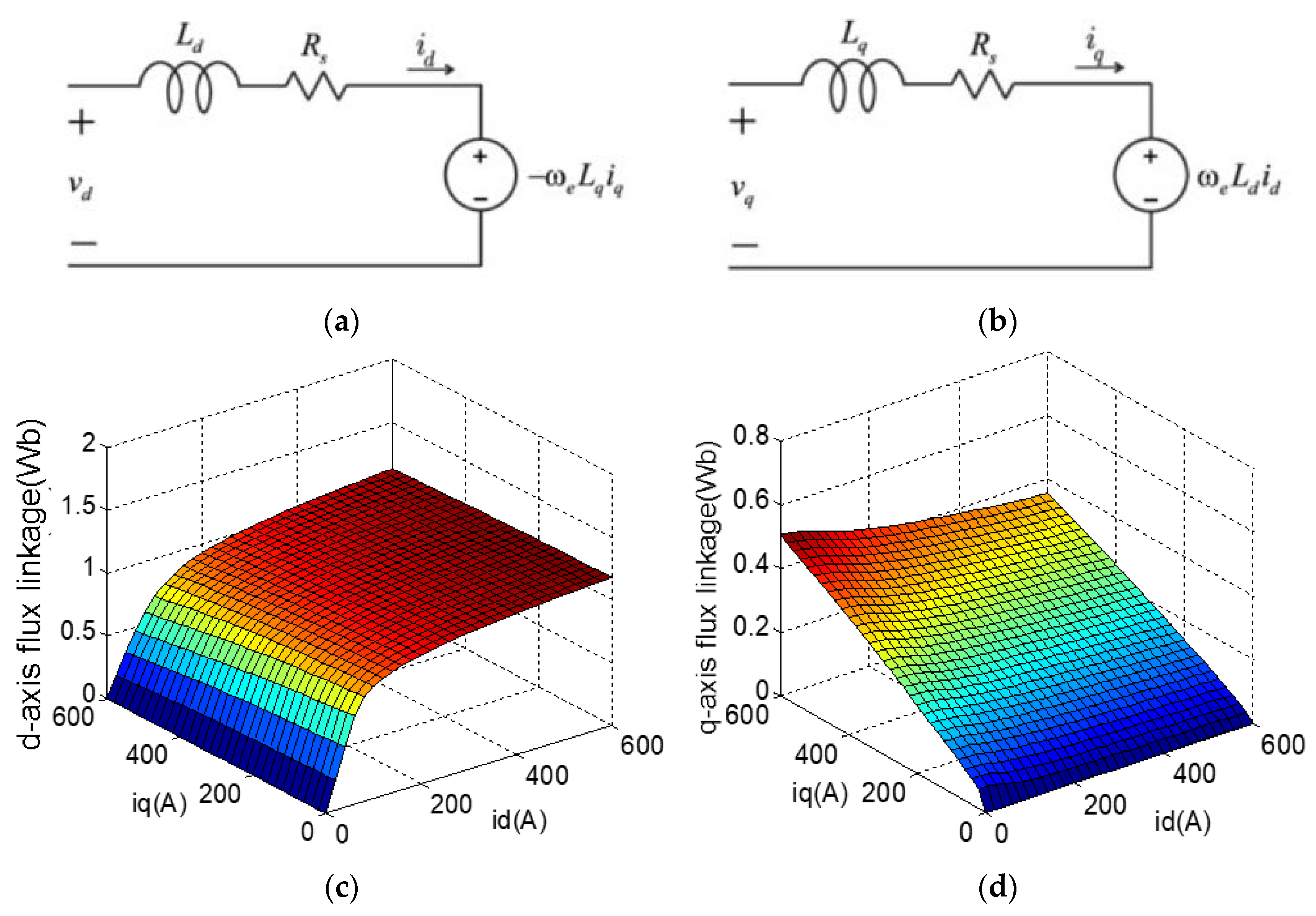
Figure 2.
MTPA, torque, current constraint, and voltage constraint in the dq-axis current plane.
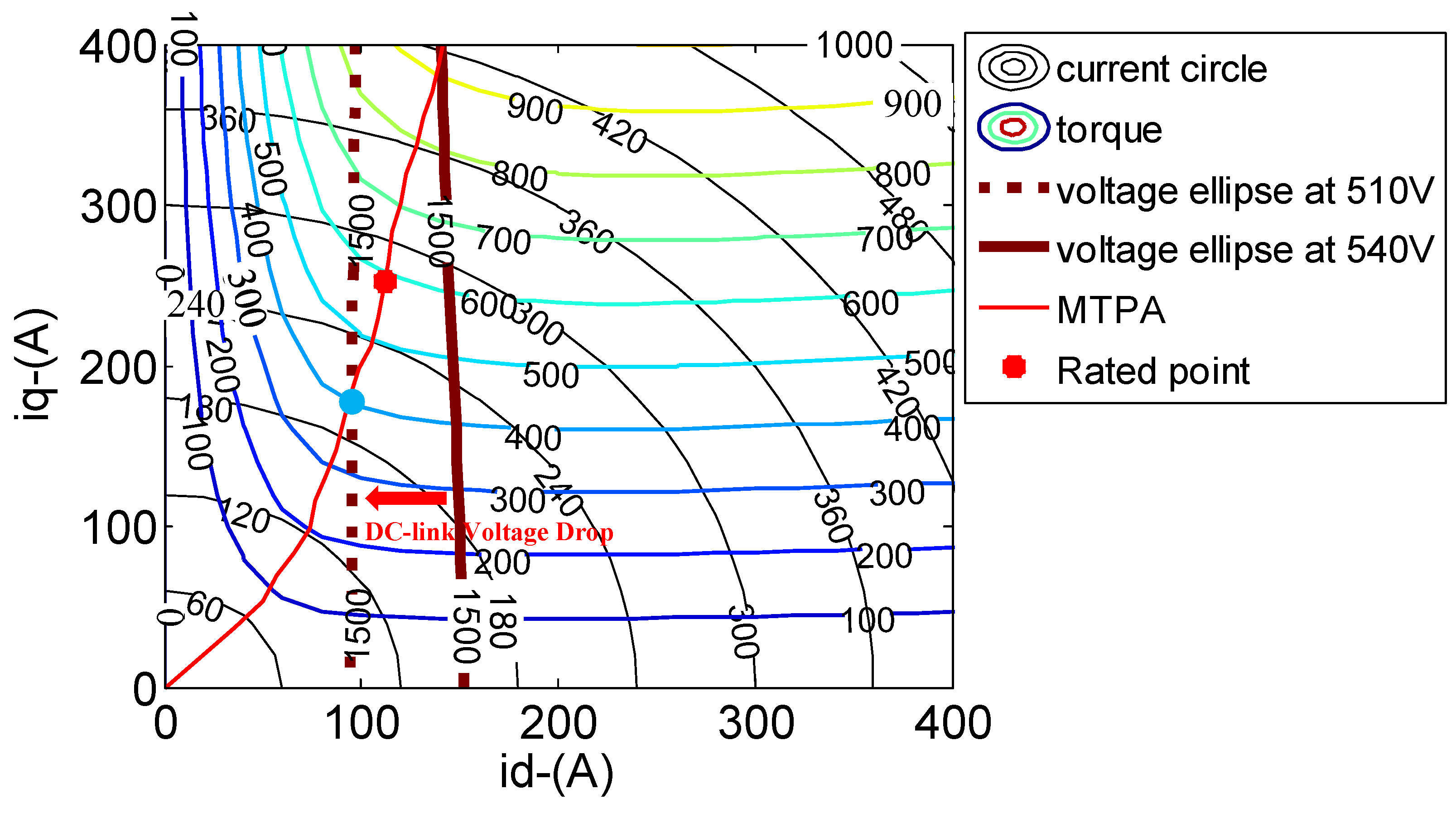
Figure 3.
Grid-connected variable-frequency SynRM drive high-power circuit.

Figure 4.
Three-phase DPWM duty cycle: (a) DPWM2, (b) 10°/50° split-clamp DPWM, (c) 20°/40° split-clamp DPWM, and (d) DPWM3.
Figure 4.
Three-phase DPWM duty cycle: (a) DPWM2, (b) 10°/50° split-clamp DPWM, (c) 20°/40° split-clamp DPWM, and (d) DPWM3.

Figure 5.
Voltage vector diagram of SynRM.
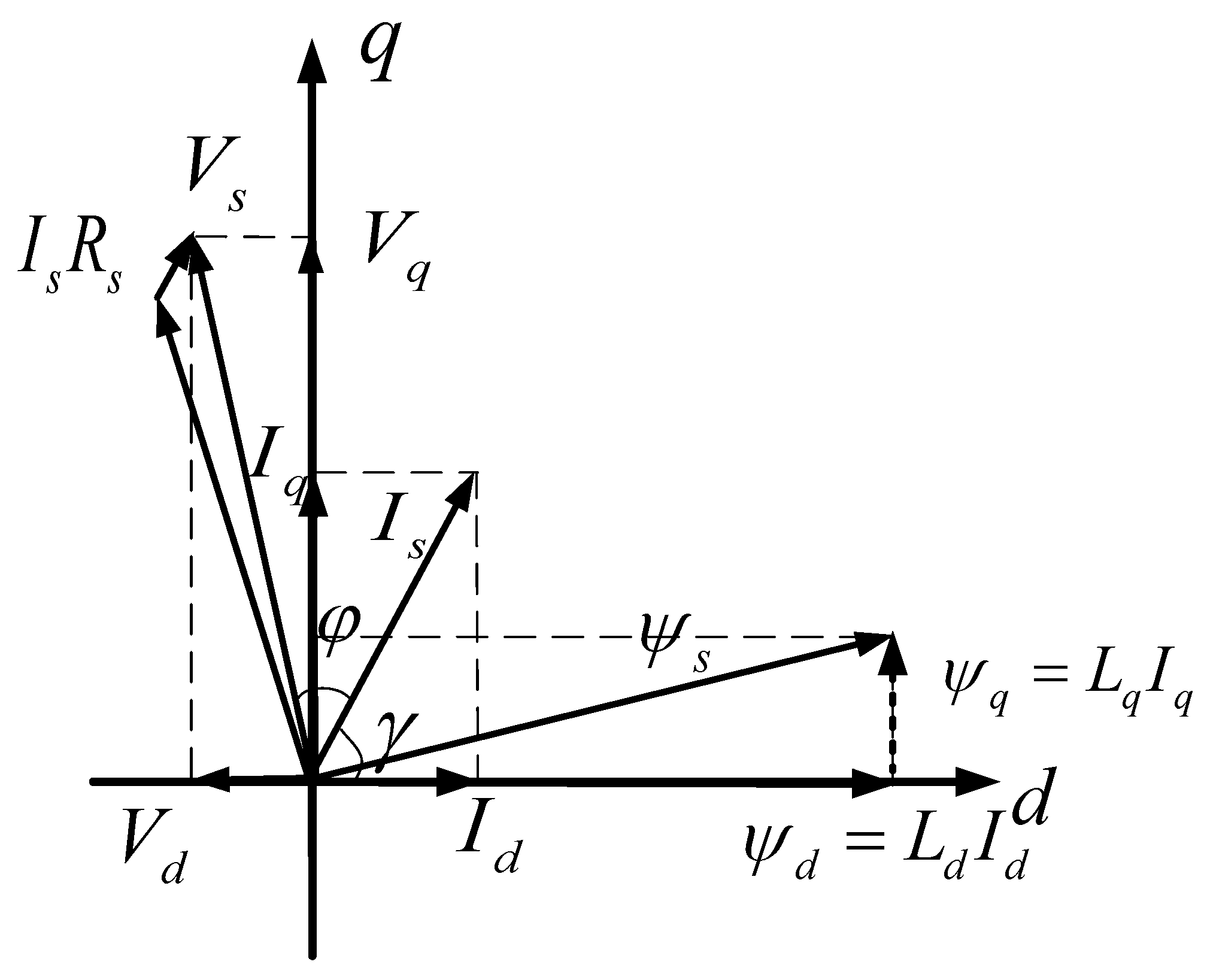
Figure 6.
Power factor of SynRM obtained from experiments at different operating points.

Figure 7.
Entire switching process for the upper switch in one carrier period: (a) switching loss and (b) DPWM1 with 45° lagging current.
Figure 7.
Entire switching process for the upper switch in one carrier period: (a) switching loss and (b) DPWM1 with 45° lagging current.
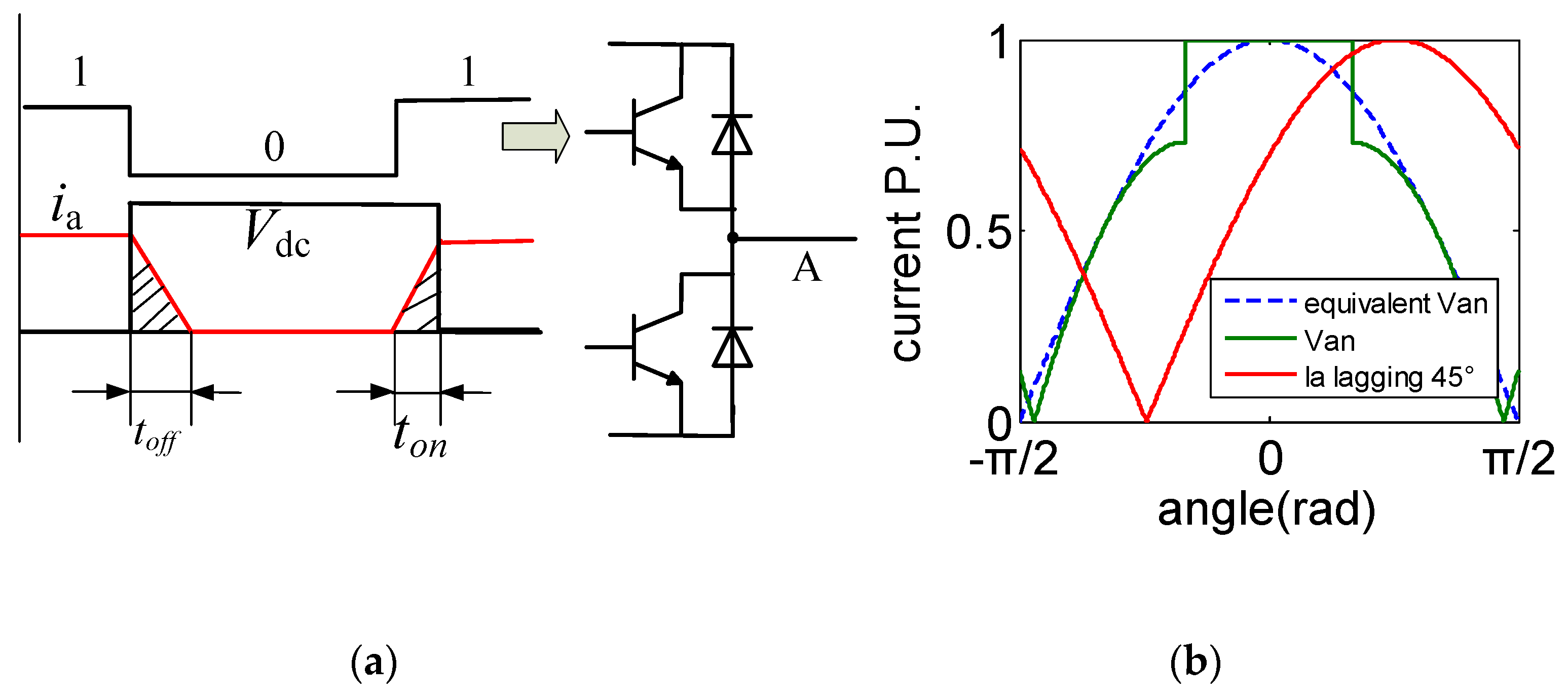
Figure 8.
Switching loss function with different DPWM switching patterns. ① DPWM0, ② intermediate patterns between DPWM0 and DPWM2, ③ DPWM2, ④ split-clamping PWM, ⑤ DPWM3.
Figure 8.
Switching loss function with different DPWM switching patterns. ① DPWM0, ② intermediate patterns between DPWM0 and DPWM2, ③ DPWM2, ④ split-clamping PWM, ⑤ DPWM3.

Figure 9.
HDF with different DPWM switching patterns: (a) same switching frequency and (b) increasing switching frequency by 1.5 times for all DPWMs.
Figure 9.
HDF with different DPWM switching patterns: (a) same switching frequency and (b) increasing switching frequency by 1.5 times for all DPWMs.
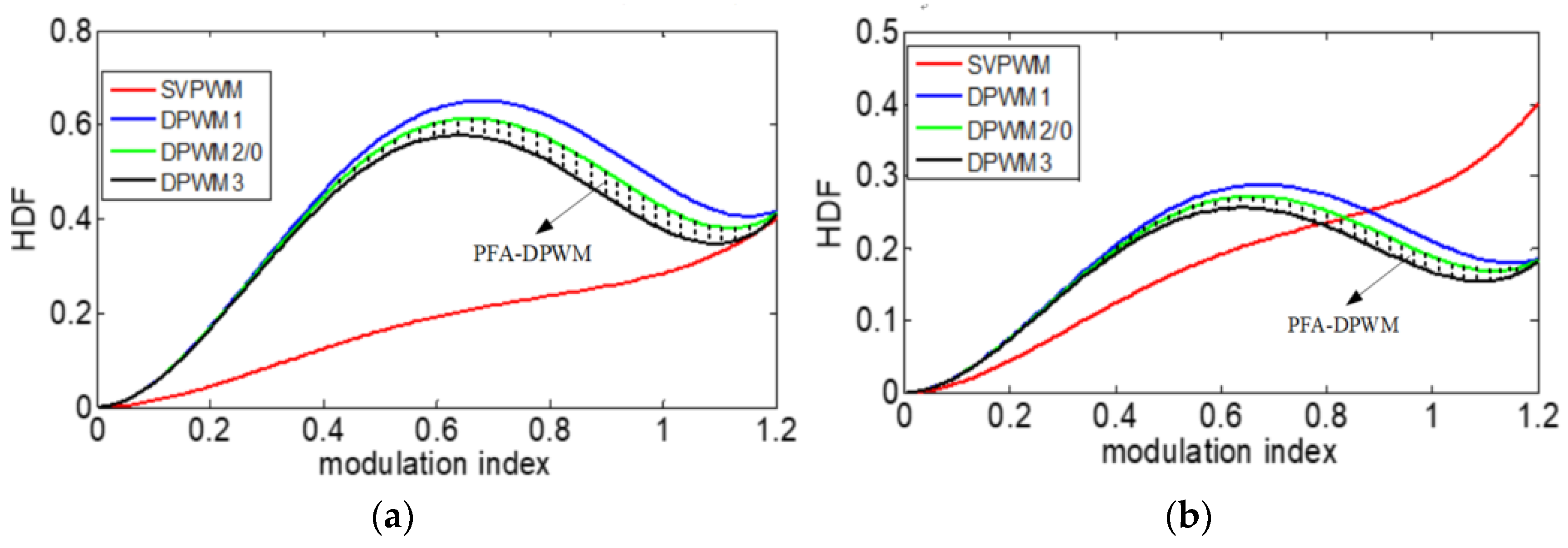
Figure 10.
DPWM with different modulation amplitudes: (a) modulation waveform and (b) equivalent line voltage.
Figure 10.
DPWM with different modulation amplitudes: (a) modulation waveform and (b) equivalent line voltage.

Figure 11.
PWM pattern selections: (a) modulation index and (b) power factor.
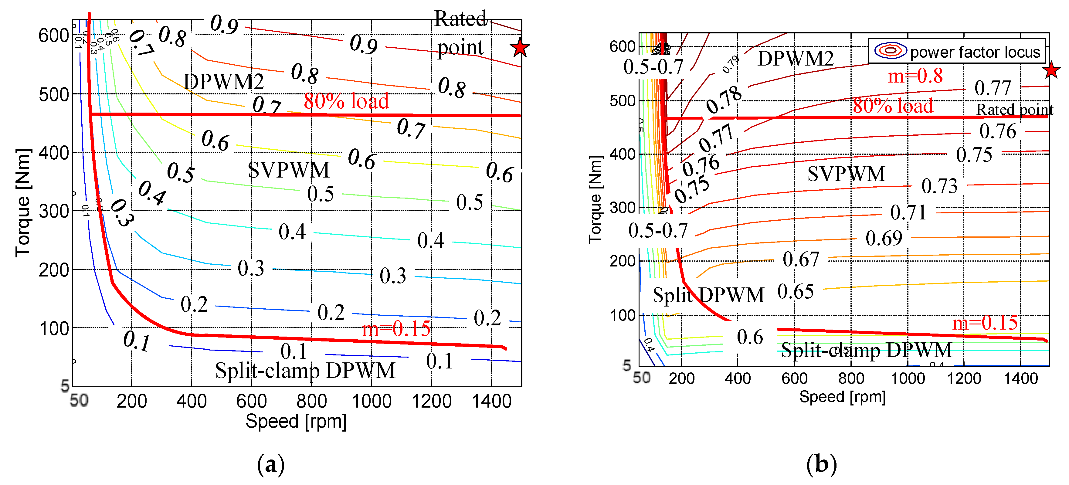
Figure 12.
Comprehensive control block of modified modulation strategy used in SynRMs: (a) control diagram; (b) proposed modulation strategy.
Figure 12.
Comprehensive control block of modified modulation strategy used in SynRMs: (a) control diagram; (b) proposed modulation strategy.
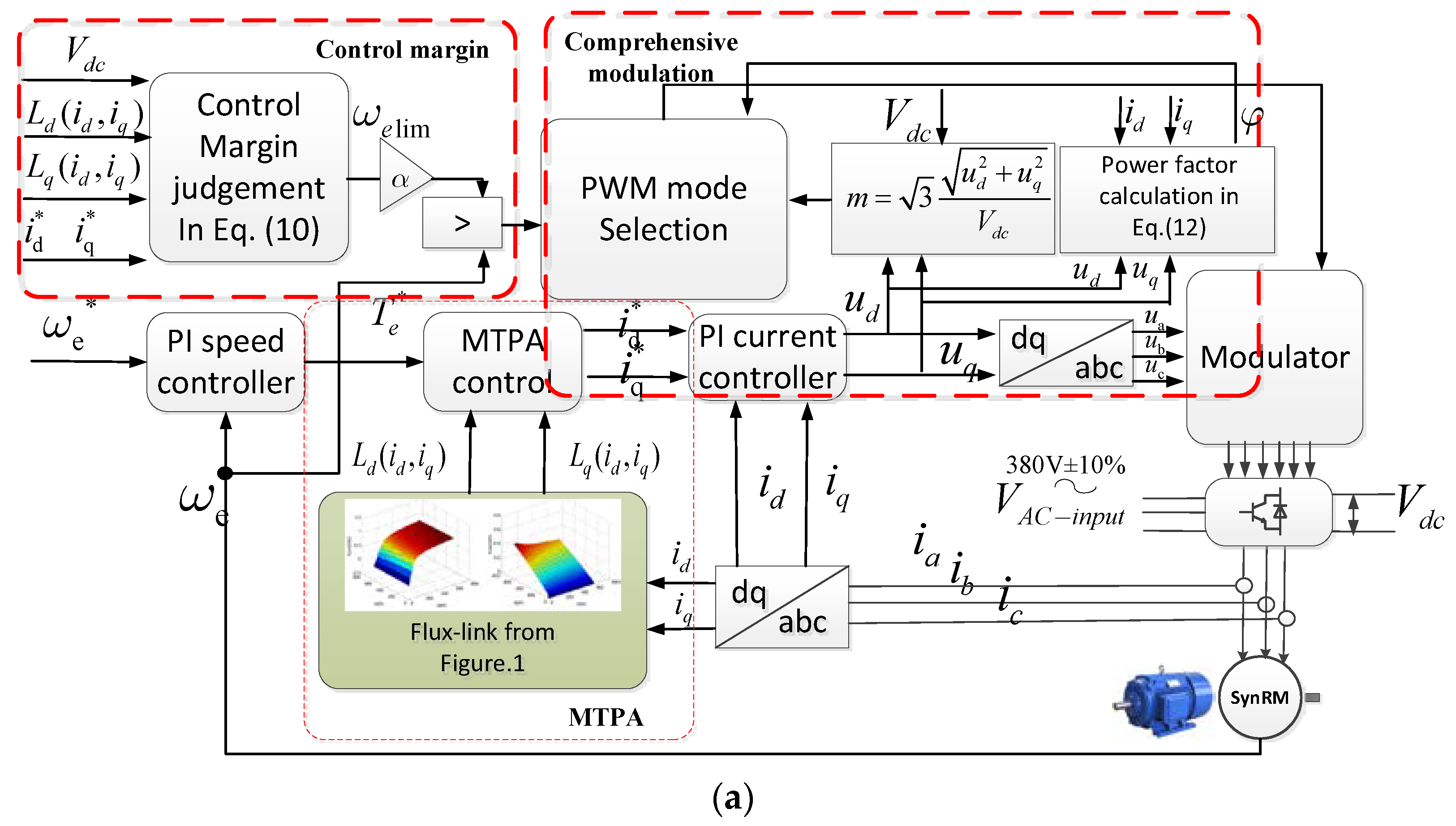

Figure 13.
Test rig: (a) 90 kW SynRM and (b) DSP-based controller.
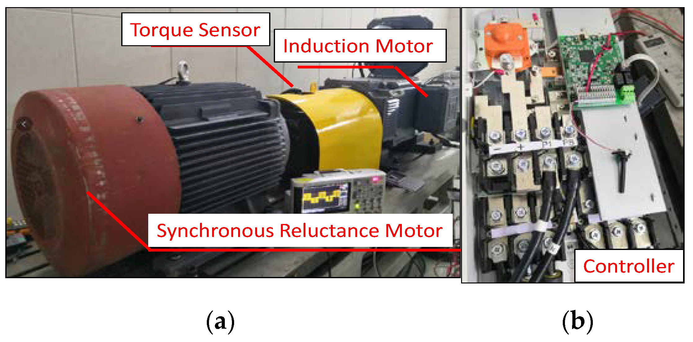
Figure 14.
Efficiency comparison for different modulation strategies: (a) 1500 rpm, 573 N.m, controller efficiency at 540 V DC-link voltage, (b) 1500 rpm, 573 N.m, motor efficiency at 540 V DC-link voltage, (c) 50 rpm, 573 N.m controller efficiency, and (d) 1500 rpm, 573 N.m motor efficiency at 500 V DC-link voltage.

Figure 15.
Experiment results of PFA-DPWM with (a) acceleration and (b) deceleration.

Figure 16.
Response to step 573 N.m load response at 1500 rpm: 40% to 100% load.
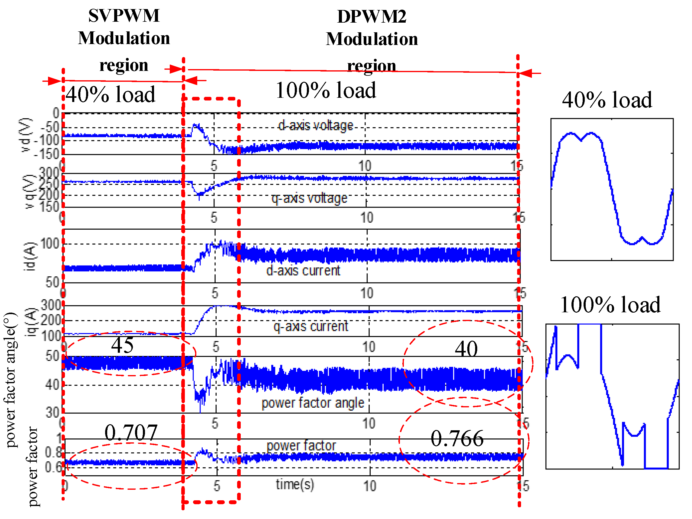
Figure 17.
Three-phase current and line voltage with DC-link voltages (a) 510 V; (b) 480 V. The red waveform: line voltage between phase A and B. The dark yellow, blue and green waveform represent phase A, B ,C current respectively.
Figure 17.
Three-phase current and line voltage with DC-link voltages (a) 510 V; (b) 480 V. The red waveform: line voltage between phase A and B. The dark yellow, blue and green waveform represent phase A, B ,C current respectively.
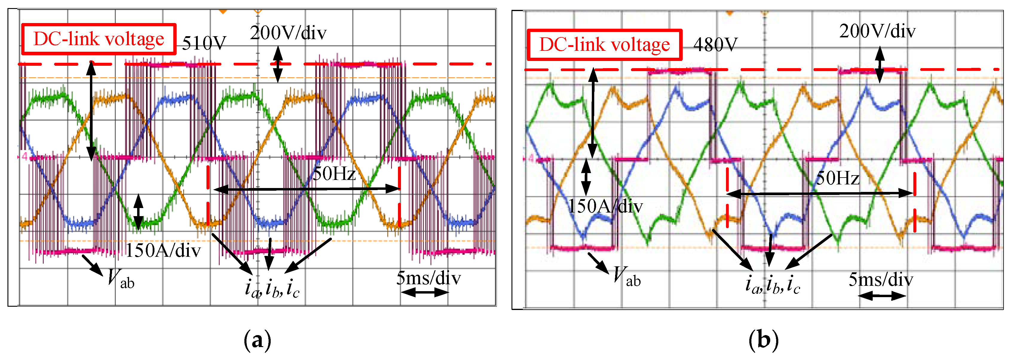
Figure 18.
DC-link voltage drop from 530 V to 475 V: (a) phase current voltage between negative DC-link voltage and phase A, (b) zoom of the first red ellipse, (c) zoom of the second red ellipse, and (d) zoom of the third ellipse.
Figure 18.
DC-link voltage drop from 530 V to 475 V: (a) phase current voltage between negative DC-link voltage and phase A, (b) zoom of the first red ellipse, (c) zoom of the second red ellipse, and (d) zoom of the third ellipse.


Table 1.
SynRM parameters.
| Parameter | Value | Unit |
|---|---|---|
| Rated mechanic power | 90 | kW |
| Rated torque | 573 | Nm |
| Rated speed | 1500 | rpm |
| Rated phase current | 193 | A-RMS |
| Rated phase voltage | 210 | V-RMS |
| Stator resistance | 0.0152 | Ω |
| Pole pairs | 2 |
Table 2.
90 kW inverter parameters.
| Parameter | Value | Unit |
|---|---|---|
| PWM frequency | 5 | kHz |
| Dead time | 4 | µs |
| Input phase voltage | 220 | V-rms |
| DC-link capacitors | 8200 | µF |
Table 3.
Rated point comparison between dpwm2 and svpwm.
| Item | DPWM2 | SVPWM |
|---|---|---|
| Current THD | 2.2% | 1.8% |
| Drive efficiency | 97.5% | 97% |
| Motor efficiency | 96.16% | 96.22% |
| System efficiency | 93.75% | 93.33% |
| Temperature (2 h run time) | 76 °C | 81 °C |
Disclaimer/Publisher’s Note: The statements, opinions and data contained in all publications are solely those of the individual author(s) and contributor(s) and not of MDPI and/or the editor(s). MDPI and/or the editor(s) disclaim responsibility for any injury to people or property resulting from any ideas, methods, instructions or products referred to in the content. |
© 2024 by the authors. Licensee MDPI, Basel, Switzerland. This article is an open access article distributed under the terms and conditions of the Creative Commons Attribution (CC BY) license (https://creativecommons.org/licenses/by/4.0/).
Share and Cite
MDPI and ACS Style
Wang, S.; Prystupa, D.; Bao, Y.; Varvolik, V.; Buticchi, G.; Zhang, H.; Degano, M. Comprehensive Modulation Strategies for Synchronous Reluctance Motor Drives Used in Weak Grids. Energies 2024, 17, 615. https://doi.org/10.3390/en17030615
AMA Style
Wang S, Prystupa D, Bao Y, Varvolik V, Buticchi G, Zhang H, Degano M. Comprehensive Modulation Strategies for Synchronous Reluctance Motor Drives Used in Weak Grids. Energies. 2024; 17(3):615. https://doi.org/10.3390/en17030615
Chicago/Turabian StyleWang, Shuo, Dmytro Prystupa, Yuli Bao, Vasyl Varvolik, Giampaolo Buticchi, He Zhang, and Michele Degano. 2024. "Comprehensive Modulation Strategies for Synchronous Reluctance Motor Drives Used in Weak Grids" Energies 17, no. 3: 615. https://doi.org/10.3390/en17030615
Note that from the first issue of 2016, this journal uses article numbers instead of page numbers. See further details here.