
Hundred-Watt Implantable TEG Module for Large-Scale Exhaust Gas Waste Heat Recovery
by
 ,
,
Zhien Gu
1, 
Shi He
1,
Xiang Li
2,
Peng Sun
2,
Jiehua Wu
2,*,
Haoyang Hu
2,
Qiang Zhang
2 and
Jun Jiang
2 1
Zhejiang Zheneng Zhenhai Gas Cogeneration Co., Ltd., Ningbo 315208, China
2
Ningbo Institute of Materials Technology and Engineering, Chinese Academy of Sciences, Ningbo 315201, China
*
Author to whom correspondence should be addressed.
Energies 2024, 17(3), 665; https://doi.org/10.3390/en17030665
Submission received: 12 November 2023
/
Revised: 11 January 2024
/
Accepted: 23 January 2024
/
Published: 30 January 2024
(This article belongs to the Section J: Thermal Management)
Abstract
:In this study, we have designed and developed an implantable thermoelectric generator (TEG) module tailored for large-scale flue gas waste heat recovery. We also have established a test stand to simulate diverse operational conditions, and systematically examined the influence of different operating conditions, including flue gas temperature, flue gas velocity, and cooling water temperature, on the electrical performance of the TEG module. When the flue gas temperature is 139 °C, the flue gas flow rate is 3.4 m/s, and the cooling water temperature is 20 °C, the TEG module operates at its peak performance. It achieves an open-circuit voltage of 856.3 V and an output power of 150.58 W. Furthermore, the TEG module demonstrates a notable power generation capacity of 3.86 kW/m3 and a waste heat recovery capacity of 135.85 kW/m3. The results prove the TEG module as an effective solution for large-scale flue gas waste heat recovery in industrial settings, contributing to sustainable energy practices. This study supports the application of thermoelectric power generation in the industrial sector, offering significant potential for advancements in energy efficiency.
1. Introduction
Energy is crucial for a nation’s development and technological advancement. It is anticipated that the industrial sector will account for 34% of the world’s total energy consumption by the year 2035 [1,2,3,4,5]. According to statistics from the American Department of Energy, around 20–50% of energy is lost in the form of waste heat, including exhaust gases, cooling water, equipment surface, and more [6,7,8,9,10,11]. Among these, exhaust gases represent the highest proportion. Given the continued population growth and the depletion of finite natural resources, waste heat recovery technologies offer an attractive solution. Thermoelectric technology based on the Seebeck effect is a sustainable approach to waste heat recovery [12,13,14,15,16]. It offers advantages, including a solid-state nature, noise-free operation, compact structure, and extended lifespan [17,18,19].
Various thermoelectric generators (TEGs) have been developed for the recovery of flue gas waste heat, particularly in industries such as the petrochemicals, thermal power plants, marine vessels, and automobile fields [20,21,22,23,24,25,26,27,28]. These demonstrate the importance of TEG technology in practical applications. Men et al. [7] propose a TEG with a cubic pipe structure for the recovery of exhaust gas waste heat. According to the simulation results, when 350 °C exhaust gas passes through the TEG, about 1.47 kW electrical energy can be generated for a pipe section surface of 1 m2. This demonstrates the significant potential of TEGs in recovering industrial flue gas waste heat. Many studies are focused on researching the application of TEGs in recovering waste heat from automotive exhaust gases. Kim et al. [20] designed a hexagonal TEG and studied its generating performance under eight commonly encountered engine operating conditions in automotive vehicles. The TEG has a size of 136 (H) mm × 141 (W) mm × 214 (L) mm, with the flue gas passing through the TEG. The output power of the hexagonal TEG ranges between 21.2 and 98.8. W. Goncalves et al., Brito et al., and Martins et al. [21,22] have designed TEG systems that utilize heat pipes to extract heat from exhaust gases to the hot side of the TEG. However, the cost of heat pipes is relatively high, making it challenging for practical engineering applications. Many major automotive companies such as BMW, Ford, Honda, and others have developed TEGs for automotive exhaust waste heat recovery [23,24,25,26]. Their designs are quite similar, with thermoelectric modules (TEMs) placed on the exhaust pipe surface to exchange heat, and they utilize engine coolant as the cold end. According to the experiment results, using TEGs can lead to a 3% reduction in fuel consumption. Li et al. [27] have developed a TEG for harvesting the waste heat from marine flue gas. The TEG’s structure includes a pipe to guide the flue gas through the TEG, and it generates a total electric power of 2.2 kW at an exhaust gas temperature of 367 °C.
In light of the aforementioned research developments, it is apparent that in TEG applications in exhaust gas waste heat recovery, the fundamental design principle involves channeling exhaust gases into a tubular TEG. However, this working principle is primarily suitable for scenarios with lower exhaust gas volumes, making it less effective for addressing the demands of larger-scale exhaust gas waste heat recovery applications, such as scenarios in thermal power plants and large boiler exhaust gas in the petrochemical industry. In such scenarios, it is challenging to introduce a large quantity of exhaust gas into the TEG. Instead, it is necessary to position the TEG within the exhaust gas flow, similar to a low-temperature economizer.
In this paper, we have developed an implantable TEG with both heat exchange and power generation capabilities, specifically designed for large-scale exhaust gas waste heat recovery, in conjunction with the low-temperature economizer’s structure. When the flue gas temperature is 139 °C, the flue gas flow rate is 3.4 m/s, and the cooling water temperature is 20 °C, the TEG module operates at its peak performance. It achieves an open-circuit voltage of 856.3 V and an output power of 150.58 W. The TEG module exhibits a power generation capacity of 3.86 kW/m3 and a waste heat recovery capacity of 135.85 kW/m3. This research provides robust support for the application of thermoelectric power generation technology in large-scale flue gas systems and holds the potential to make significant strides in the energy sector.
2. Test Stand and TEG
2.1. Test Stand Build
The aim of this study is to design and develop a TEG suitable for large-scale flue gas waste heat recovery. We built a test stand to assess the generating performance of the TEG under different operating conditions, as shown in the schematic diagram in Figure 1a. Figure 1b depicts the image of the experiment plate after the implementation of insulation measures. The setup consists of the following components. An industrial hot air blower (A) that supplies flue gas with varying temperature and velocity. A gas flue (B) providing large-scale flue gas scenarios where the TEG module (C) is placed. A flue gas recirculation pipe (D) that pumps the high-temperature flue gas from the outlet back to the inlet to save energy. A chiller (E) and some cooling water pipeline (F), which offers cooling water for the TEG cold end; a stop valve (H) and flow meters (G, HXLD–DN8) are installed to control and monitor the flow of cooling water. A multi-channel temperature acquisition device (I, EX3008, Toprie, Shenzhen, China) is used to acquire the temperature of the flue gas, TEG, and cooling water. An electronic load meter (J, IT8512B+, ITECH, Nanjing, China) is used to offer a load resistance and test power generation parameters.
We conducted tests on the power generation performance of the TEG under various operating conditions using the following procedure:
- Set the inlet flue gas temperature and velocity by adjusting the parameters of the hot air blower.
- Set the cooling water temperature and flow rate through controlling the chiller parameters and cutoff valve.
- When the desired flue gas temperature and cooling water temperature are reached, stabilize for 10 min to ensure uniform TEG temperature.
- Test the TEG’s voltage, current, and other parameters.
- After completing the tests, turn off the hot air blower’s heating element. Once the flue gas temperature has dropped to room temperature, proceed to turn off all the equipment.
The parameters of the experimental test stand are presented in Table 1. The flue dimensions can reach 605 mm × 506 mm × 435 mm, and we will design 100-watt level TEG modules based on this size. The test stand is capable of supplying flue gas with a maximum temperature of 200 °C and a maximum flow rate of 3.4 m/s. Additionally, it can provide cooling water with temperatures ranging from 5 to 40 °C and flow rates from 0 to 0.743 m3/h. The constructed experimental test stand essentially meets the flue gas parameters of waste heat boilers in power plants.
2.2. TEG Design
TEGs typically consist of three main components: the hot-side heat exchanger, TEMs, and cold-side heat exchanger. In this paper, the TEG will be placed in the flue. Therefore, we designed the hot-side heat exchanger as a plate structure with fins, similar to a tubular heat exchanger. The cold-side heat exchanger utilizes a cooling water plate, and the temperature-controlled cooling water is provided by the chiller. The used TEMs are commercial devices made from bismuth telluride materials. They have dimensions of 25 mm (L) × 25 mm (W) × 3.5 mm (H), with 126 pairs of thermoelectric legs. Finally, the overall TEG structure resembles a sandwich, with the following layers from top to bottom: finned heat exchanger, TEM, water-cooled plate, TEM, and finned heat exchanger, as shown in Figure 2a. To enhance the heat transfer efficiency, we apply thermally conductive silicone grease on both surfaces of the TEMs to reduce thermal resistance. Additionally, a bolt pressure mechanism is introduced to increase contact density, further minimizing contact thermal resistance and improving TEG integration.
The parameters of the fin structure, which include the fin thickness, height, and spacing, play a crucial role in determining the heat exchanger’s heat transfer capacity. In traditional tubular heat exchangers, the fin thickness is typically around 1 mm, the height is approximately 16 mm, and the spacing is about 3 mm. However, because TEMs introduce the highest thermal resistance within the heat exchange system, ensuring the establishment of a significant temperature difference is vital for enhancing the power generation performance of the TEG. This requirement makes it challenging for conventional heat exchanger fin parameters to create a substantial temperature difference across the TEMs. To address this issue, we conducted a simulation to optimize the fin parameters using COMSOL 5.7 software. The fin heat exchanger structure employs aluminum materials to improve the heat transfer efficiency. The height and spacing of the fins are the two most critical parameters, as they determine the heat exchange surface area with the flue gas. Therefore, we primarily determined the optimal values for these two parameters through the simulation.
The simulation’s boundary conditions are as follows:
- We set the fin thickness to 1 mm, following the design of traditional heat exchangers.
- The temperature conditions are as outlined below: Inlet flue gas temperature is 130 °C, flue gas flow velocity is 1.8 m/s, and cooling water temperature is 20 °C. This represents one operating condition of flue gas waste heat.
- The contact thermal resistance has a certain impact on the heat transfer between the TEG’s hot side and the flue gas [29]. We use simulations only to confirm the approximate size range of the fins. In this scenario, the influence of the contact thermal resistance is minimal. Therefore, during simulations, we are disregarding the contact thermal resistance.
- We performed a parametric scan for the fin height and spacing, with the height ranging from 25 mm to 55 mm in 10 mm increments, and the spacing ranging from 2 mm to 10 mm in 2 mm increments.
- The temperature difference at both ends of the TEM serves as the criterion for evaluation, with higher temperature differences indicating more favorable fin parameters.
Figure 2b illustrates one of the simulation scenarios, showing that the fin temperature at the inlet of the flue gas is slightly higher than at the outlet, with a difference of approximately 20 °C. Therefore, we have set the bottom of the fin heat exchanger structure to 10 mm to achieve both uniform heating and the ability to withstand pre-tensioning without bending.
The simulation results are presented in Table 2. It can be observed that as the fin height increases and the spacing decreases, the temperature difference between the two ends of the TEM also increases. A very small gap between the fins can lead to an increased pressure drop in the flue gas. To maintain a balance, we have set the gap between the fins to 4 mm, which is consistent with the spacing found in traditional heat exchangers. To facilitate the machining process, we have set the height of the fins to 45 mm.
Finally, the TEG structure and parameters developed by us are presented in Table 3. We regard it as a TEG unit; its physical dimensions are 495 mm × 100 mm × 130 mm. It consists of two upper and lower finned heat exchangers, 20 TEMs, and a water-cooling plate. The 20 TEMs in each TEG unit are connected in series. Finally, in conjunction with the dimensions of the flue, we produced six TEG units, as shown in Figure 3a. The TEG units underwent insulation treatment to prevent contact between the flue gas and the cooling water plate. Figure 3b displays a photograph of the six TEG units placed inside the flue, referred to as the TEG module. A total of 240 TEMs are used in the TEG module. We will test the power generation performance of the TEG module under various operating conditions.
3. Results and Discussion
We placed the TEG module inside the flue and needed to confirm the electrical connections for the six TEG units. We have designed four series–parallel combination methods: I involve serially connecting all six TEG units, II entails serially connecting three TEG units and then parallel connecting two of these serial combinations, III includes serially connecting two TEG units and then parallel connecting three of these serial combinations, and IV involves parallel connecting all six TEG units, as shown in Figure 4.
We determined the optimal configuration based on the power generation performance. The experimental conditions are as follows: cooling water temperature set at 20 °C, flue gas inlet temperature set at 90 °C, and air velocity set at 1.8 m/s. The results of voltage-current and power-current are exhibited in Figure 5. As the number of series and parallel connections increases, the open-circuit voltage significantly decreases, in line with the characteristics of series and parallel circuits. The output power of the TEG module decreases, with an increasing number of parallel connections. Parallel circuits can induce backflow, leading to energy losses in the circuit. Based on the experimental results, we ultimately used the all-series connection method (I) for the subsequent experiments.
The electrical performance of the fabricated TEG module is determined by the parameters of the hot source flue gas and the cold source cooling water, such as the temperature and the flow velocity of the flue gas and cooling water. In the experiment, we maintained a fixed cooling water flow rate of 0.743 m3/h, with a primary focus on studying the impact of the other three variables on the electrical performance of the TEG module. The flue gas temperature ranged from approximately 70 to 140 °C, with the flue gas flow rates categorized into four parameters: 2.0, 2.4, 2.8, and 3.4 m/s. The cooling water temperature spanned from about 20 to 40 °C. Figure 6 presents the open-circuit voltage and output power of the TEG module under different operating conditions. Both the open-circuit voltage and output power increase with the increasing flue gas temperature and flow velocity as well as with the decreasing cooling water temperature. The performance of the TEG module is primarily determined by the temperature difference established at the ends of the TEMs. Higher flue gas temperatures and faster flue gas flow rates enhance the heat exchange at the hot end, raising the hot end temperature. Simultaneously, low cooling water temperatures ensure that the TEG’s cold end remains in a low-temperature state, enabling a higher temperature difference to be established at the ends of the TEMs. From the three-dimensional surface plots, it is evident that the temperatures of the flue gas and cooling water have a more significant impact on the TEG module’s power generation performance compared to the flue gas flow velocity. Under the optimal conditions with a flue gas temperature of 139 °C, flue gas flow velocity of 3.4 m/s, and cooling water temperature of 20 °C, the TEG module achieves its peak power generation performance. This results in an open-circuit voltage of 856.3 V and an output power of 150.58 W. The overall volume of the developed TEG module is 0.039 m3, and its volume power density is 3.86 kW/m3. This further demonstrates the effectiveness of the implantable TEG module we have developed for recovering waste heat from large-scale flue gases.
The thermal energy (Qin, J) flowing through the TEG module is partly converted into electrical energy (Qe, J) by the TEG, while the rest of the thermal energy (Qw, J) is carried away by the cooling water. This can be represented by Formula (1). Qw can also be referred to as the thermal energy recovered by the cooling water. Formula (1) can be expressed as a power equation, as shown in Formula (2).
Qin = Qe + Qw
Pin = Pe + Pw
We already have the output power (Pe, W) of the TEG module under different operating conditions according to Figure 6b. The heat energy carried (Pw, W) away by the cooling water can be calculated based on the formula for calculating enthalpy change, as shown in Formula (3).
where m (kg) is the mass of the cooling water, (Hout − Hin) (J/kg) is the enthalpy difference of the cooling water between the outlet and inlet, t (s) is the time. The flow rate is 0.743 m3/h, that is to say 0.206 kg/s. ΔH can be obtained from the water thermodynamic table. In the previous experiments, we determined that the effect of the flue gas velocity is smaller than that of the flue gas and cooling water temperature. Therefore, we kept the flue gas velocity fixed at 3.4 m/s and investigated the heat recovery of the cooling water at different flue gas and cooling water temperatures, as seen in Figure 7. It is evident that as the flue gas temperature increases and the cooling water temperature decreases, the recovered thermal energy also increases. This is because the temperature difference is the driving force for heat exchange, and the higher the temperature difference, the greater the heat transfer. Therefore, TEGs should be installed in locations with as high a temperature difference as possible. The range of heat recovery by the TEG module is from 1.44 kW (flue gas temperature 78 °C, cooling water temperature 40 °C) to 5.30 kW (flue gas temperature 132 °C, cooling water temperature 24 °C). In that case, the TEG module’s capacity to recover waste heat is about 135.85 kW/m3. The recovered heat can be stored in a heat reservoir or utilized in other processes that require heating in a power plant.
Pw = Q/t = m × (Hout − Hin)/t
Combining the above parameters, we can also determine the conversion efficiency (η) of the developed TEG module, which can be calculated using Formula (4). The conversion efficiency of the TEG module across various experimental conditions is illustrated in Figure 8. The observed trend in the conversion efficiency closely parallels the electrical performance of the TEG module. It is evident that the TEG module achieves a higher conversion efficiency when exposed to a higher flue gas temperature and velocity, while maintaining a lower cooling water temperature. After filtering out some of the discrete data points, the TEG module’s conversion efficiency reaches 3.24% under conditions where the flue gas temperature is 139 °C, the flue gas velocity is 3.4 m/s, and the cooling water temperature is 20 °C. This outcome is consistent with the conversion efficiency of a single TEM under a similar temperature difference, which further underscores the TEG module’s minimal system losses and presents the performance of the TEMs.
η = Pe/Pin × 100% = Pe/(Pe + Pw) × 100%
4. Conclusions
In summary, the experimental test stand for large-scale flue gas waste heat recovery was successfully designed and constructed. The TEG module within this setup demonstrates efficient power generation capabilities. The parameters of the flue gas temperature, velocity, and cooling water temperature are found to significantly impact the TEG module performance, with higher flue gas temperatures and velocities, as well as lower cooling water temperatures, leading to better results. The temperatures of the flue gas and cooling water have a more significant impact on the TEG module’s power generation performance compared to the flue gas flow velocity. The TEG module’s conversion efficiency aligns with the expectations, and it showcases minimal system losses, highlighting the performance of the individual TEMs. Under optimal conditions, with a flue gas temperature of 139 °C, a flue gas flow rate of 3.4 m/s, and a cooling water temperature of 20 °C, the TEG module exhibits its peak performance. This results in an open-circuit voltage of 856.3 V and an impressive output power of 150.58 W. In addition, the TEG module shows an impressive power generation capacity of 3.86 kW/m3 and a remarkable waste heat recovery capacity of 135.85 kW/m3. Overall, the TEG module proves to be an effective means of recovering heat from large-scale flue gases, offering the potential for applications in various industrial processes and power generation systems.
Author Contributions
Z.G., S.H., P.S. and J.J. designed this work. Z.G. and X.L. developed the TEG module and the test stand, and carried out the generating performance. H.H. and Q.Z. performed the calculations, and performed the data curation. Z.G., S.H., P.S. and J.W. analyzed the experimental data and wrote and edited this manuscript. J.J. provided the funding acquisition. All authors have read and agreed to the published version of the manuscript.
Funding
This research was funded by the National Natural Science Foundation of China (U21A2079, and 52002382), Zhejiang Provincial Key R&D Program (2021C01026), Zhejiang Provincial Natural Science Foundation of China (LR21E020002), Youth Innovation Promotion Association CAS (2019298), Zhejiang Provincial High-level Talent Special Support Plan (2020R52032), and Ningbo Key Research and Development Plan (2022Z187). The National Funding Program for Postdoctoral Researchers of China (Grant No. GZB20230786).
Data Availability Statement
All data used are reported here and/or in the cited literature sources.
Conflicts of Interest
There are no conflicts of interest to declare.
Nomenclature
| TEG | Thermoelectric generator |
| TEM | Thermoelectric module |
| Qin | Thermal energy flow through the TEG |
| Qe | Electrical energy generated by the TEG |
| Qw | Thermal energy recovered by the cooling water |
| Pin | Thermal power through the TEG |
| Pe | Electrical power generated by the TEG |
| Pw | Thermal power recovered by the cooling water |
| q | The flow rate of the cooling water |
| ΔH | The enthalpy difference of cooling water between the inlet and outlet |
| t | Unit time with value for 1 s |
| η | Conversion efficiency of the TEG |
References
- Lee, C.; Yu, B.; Lee, S. An analysis of the thermodynamic efficiency for exhaust gas recirculation-condensed water recirculation-waste heat recovery condensing boilers. Energy 2015, 86, 267–275. [Google Scholar] [CrossRef]
- Oyedepo, S.O.; Fakeye, B.A. Waste heat recovery technologies: Pathway to sustainable energy development. J. Therm. Eng. 2021, 7, 324–348. [Google Scholar] [CrossRef]
- Remeli, M.F.; Tan, L.; Date, A.; Singh, B.; Akbarzadeh, A. Simultaneous power generation and heat recovery using a heat pipe assisted thermoelectric generator system. Energy Convers. Manag. 2015, 91, 110–119. [Google Scholar] [CrossRef]
- Attar, A.; Lee, H.; Weera, S. Experimental Validation of the Optimum Design of an Automotive Air–to–Air Thermoelectric Air Conditioner (TEAC). J. Electron. Mater. 2015, 44, 2177–2185. [Google Scholar] [CrossRef]
- Sakdanuphab, R.; Sakulkalavek, A. Design, empirical modeling and analysis of a waste–heat recovery system coupled to a traditional cooking stove. Energy Convers. Manag. 2017, 139, 182–193. [Google Scholar] [CrossRef]
- Campana, F.; Bianchi, M.; Branchini, L.; De Pascale, A.; Peretto, A.; Baresi, M.; Fermi, A.; Rosetti, N.; Vescovo, R. ORC waste heat recovery in European energy intensive industries: Energy & GHG savings. Energy Convers. Manag. 2013, 76, 244–252. [Google Scholar]
- Men, F.; Chen, L.; Feng, Y.; Xiong, B. Thermoelectric generator for industrial gas phase waste heat recovery. Energy 2017, 135, 83–90. [Google Scholar]
- Angeline, A.A.; Asirvatham, L.G.; Hemanth, D.J.; Jayakumar, J.; Wongwises, S. Performance prediction of hybrid thermoelectric generator with high accuracy using artificial neural networks. Sustain. Energy Technol. Assess. 2019, 33, 53–60. [Google Scholar] [CrossRef]
- Yu, S.H.; Du, Q.; Diao, H.; Shu, G.Q.; Jiao, K. Effect of vehicle driving conditions on the performance of thermoelectric generator. Energy Convers. Manag. 2015, 96, 363–376. [Google Scholar] [CrossRef]
- Stijepovic, M.Z.; Linke, P. Optimal waste heat recovery and reuse in industrial zones. Energy 2011, 13, 341–363. [Google Scholar]
- Miró, L.; Brückner, S.; Cabeza, L.F. Mapping and discussing Industrial Waste Heat (IWH) potentials for different countries. Renew. Sustain. Energy Rev. 2015, 51, 847–855. [Google Scholar] [CrossRef]
- Suter, C.; Jovanovic, Z.R.; Steinfeld, A. A 1kWe thermoelectric stack for geothermal power generation–Modeling and geometrical optimization. Appl. Energy 2012, 99, 379–385. [Google Scholar] [CrossRef]
- Weng, C.-C.; Huang, M.-J. A study of using a thermoelectric generator to harvest energy from a table lamp. Energy 2014, 76, 788–798. [Google Scholar] [CrossRef]
- Özdemir, A.E.; Köysal, Y.; Özbas, E.; Atalay, T. The experimental design of solar heating thermoelectric generator with wind cooling chimney. Energy Convers. Manag. 2015, 98, 127–133. [Google Scholar] [CrossRef]
- Al-Nimr, M.d.A.; Tashtoush, B.M.; Jaradat, A.A. Modeling and simulation of thermoelectric device working as a heat pump and an electric generator under Mediterranean climate. Energy 2015, 90, 1239–1250. [Google Scholar] [CrossRef]
- Xiao, D.; Sun, P.; Wu, J.; Zhang, Y.; Wu, J.; Liu, G.; Hu, H.; Hu, J.; Tan, X.; He, S. Thermoelectric Generator Design and Characterization for Industrial Pipe Waste Heat Recovery. Processes 2023, 11, 1714. [Google Scholar] [CrossRef]
- Orr, B.; Akbarzadeh, A.; Mochizuki, M.; Singh, R. A review of car waste heat recovery systems utilizing thermoelectric generators and heat pipes. Appl. Therm. Eng. 2016, 101, 490–505. [Google Scholar] [CrossRef]
- Kim, T.Y.; Negash, A.A.; Cho, G. Experimental study of energy utilization effectiveness of thermoelectric generator on diesel engine. Energy 2017, 128, 531–539. [Google Scholar] [CrossRef]
- Jaziri, N.; Boughamoura, A.; Müller, J.; Mezghani, B.; Tounsi, F.; Ismail, M. A comprehensive review of Thermoelectric Generators: Technologies and common applications. Energy Rep. 2020, 6, 264–287. [Google Scholar] [CrossRef]
- Kim, T.; Kwak, J.; Kim, B. Energy harvesting performance of hexagonal shaped thermoelectric generator for passenger vehicle applications: An experimental approach. Energy Convers. Manag. 2018, 160, 14–21. [Google Scholar] [CrossRef]
- Goncalves, L.M.; Martins, J.; Antunes, J.; Rocha, R.; Brito, F.P. Heat-pipe assisted thermoelectric generators for exhaust gas applications. ASME Int. Mech. Eng. Congr. Expo. 2010, 5, 1387–1396. [Google Scholar]
- Brito, F.P.; Martins, J.; Hançer, E.; Antunes, N.; Gonçalves, L.M. Thermoelectric exhaust heat recovery with heat pipe-based thermal control. J. Electron. Mater. 2015, 44, 1984–1997. [Google Scholar] [CrossRef]
- Martins, J.; Goncalves, L.M.; Antunes, J.; Brito, F.P. Thermoelectric Exhaust Energy Recovery with Temperature Control through Heat Pipes; SAE Technical Paper; SAE: Warrendale, PA, USA, 2011. [Google Scholar]
- LaGrandeur, J.; Crane, D.; Hung, S.; Mazar, B.; Eder, A. Automotive waste heat conversion to electric power using skutterudite, TAGS, PbTe and BiTe. In Proceedings of the 25th International Conference on Thermoelectrics, Vienna, Austria, 6–10 August 2006; pp. 343–348. [Google Scholar]
- Hussain, Q.E.; Brigham, D.R.; Maranville, C.W. Thermoelectric exhaust heat recovery for hybrid vehicles. SAE Int. J. Engines. 2009, 2, 1132–1142. [Google Scholar] [CrossRef]
- Mori, M.; Yamagami, T.; Sorazawa, M.; Miyabe, T.; Takahashi, S.; Haraguchi, T. Simulation of fuel economy effectiveness of exhaust heat recovery system using thermoelectric generator in a series hybrid. SAE Int. J. Mater. Manuf. 2011, 4, 1268–1276. [Google Scholar] [CrossRef]
- Li, G.; Yin, J.; Zheng, Y.; Guo, W.; Tan, Y.; Ye, C. Analytical design model for waste heat thermoelectric generator and experimental verification. Energy Convers. Manag. 2022, 252, 115034. [Google Scholar] [CrossRef]
- Saha, M.; Tregenza, O.; Twelftree, J.; Hulston, C. A review of thermoelectric generators for waste heat recovery in marine applications. Sustain. Energy Technol. Assess. 2023, 59, 103394. [Google Scholar] [CrossRef]
- Tregenza, O.; Saha, M.; Hutasoit, N.; Hulston, C. An experimental evaluation of the thermal interface resistance between cold sprayed copper/ laser-textured alumina bi-layered composites. Int. J. Heat Mass Transfer. 2022, 188, 122606. [Google Scholar] [CrossRef]
Figure 1.
(a) Schematic of the test stand (A. industrial hot air blower; B. gas flue; C. TEG modules; D. flue gas recirculation piping; E. chiller; F. cooling water pipeline; G. flowmeter; H. stop valve; I. multi-channel temperature acquisition device; J. electronic load meter). (b) Image of the test stand.

Figure 2.
(a) Schematic of the TEG. (b) Simulation results for TEG temperature distribution.
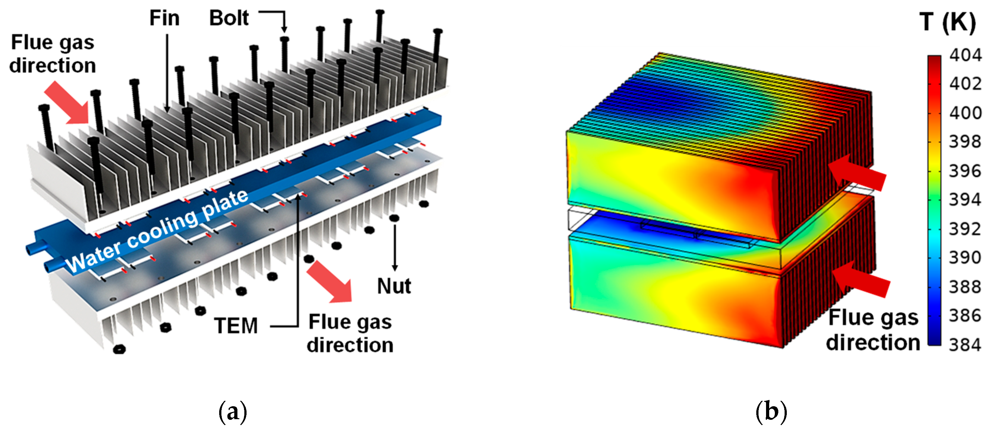
Figure 3.
(a) Image of six TEG units. (b) Picture of the TEG modules in the flue.

Figure 4.
Four series–parallel combination methods.
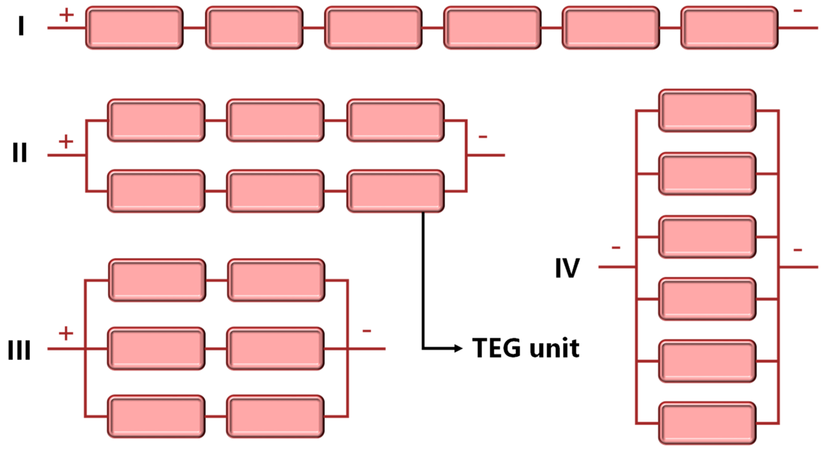
Figure 5.
Open-circuit voltage (a) and output power (b) under different series–parallel configurations.
Figure 5.
Open-circuit voltage (a) and output power (b) under different series–parallel configurations.
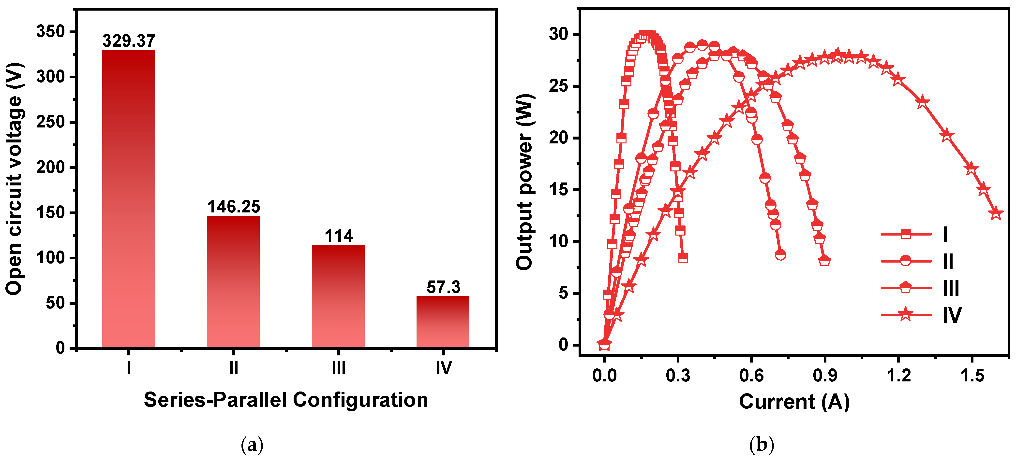
Figure 6.
Open-circuit voltage (a) and output power (b) of TEG module under different operating conditions.
Figure 6.
Open-circuit voltage (a) and output power (b) of TEG module under different operating conditions.
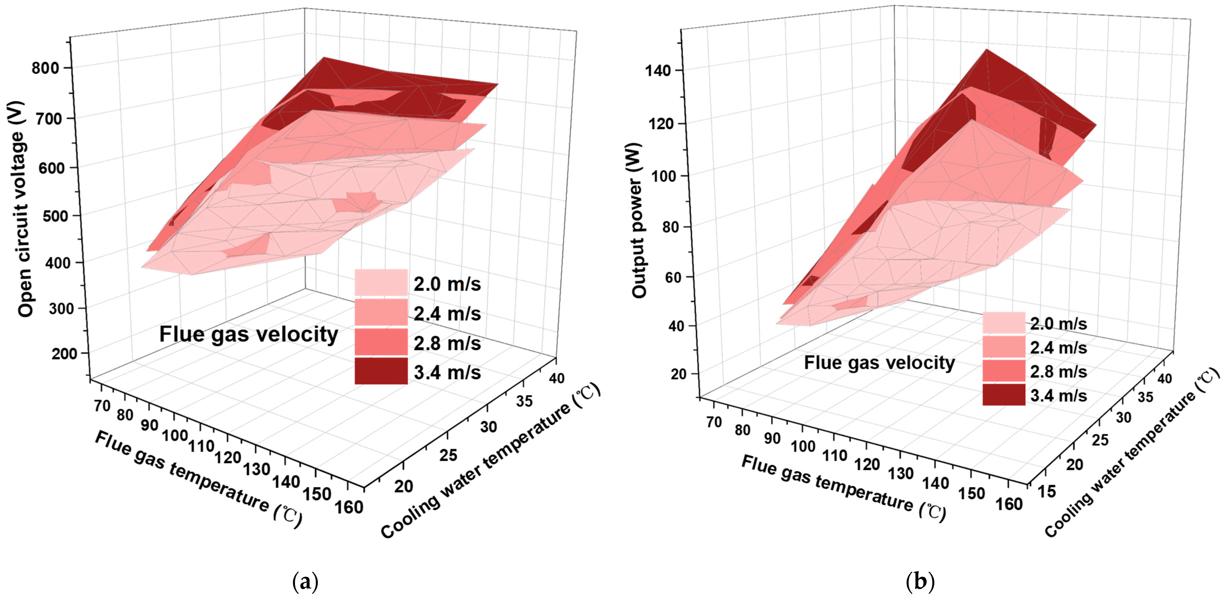
Figure 7.
Thermal energy recovered by the cooling water.
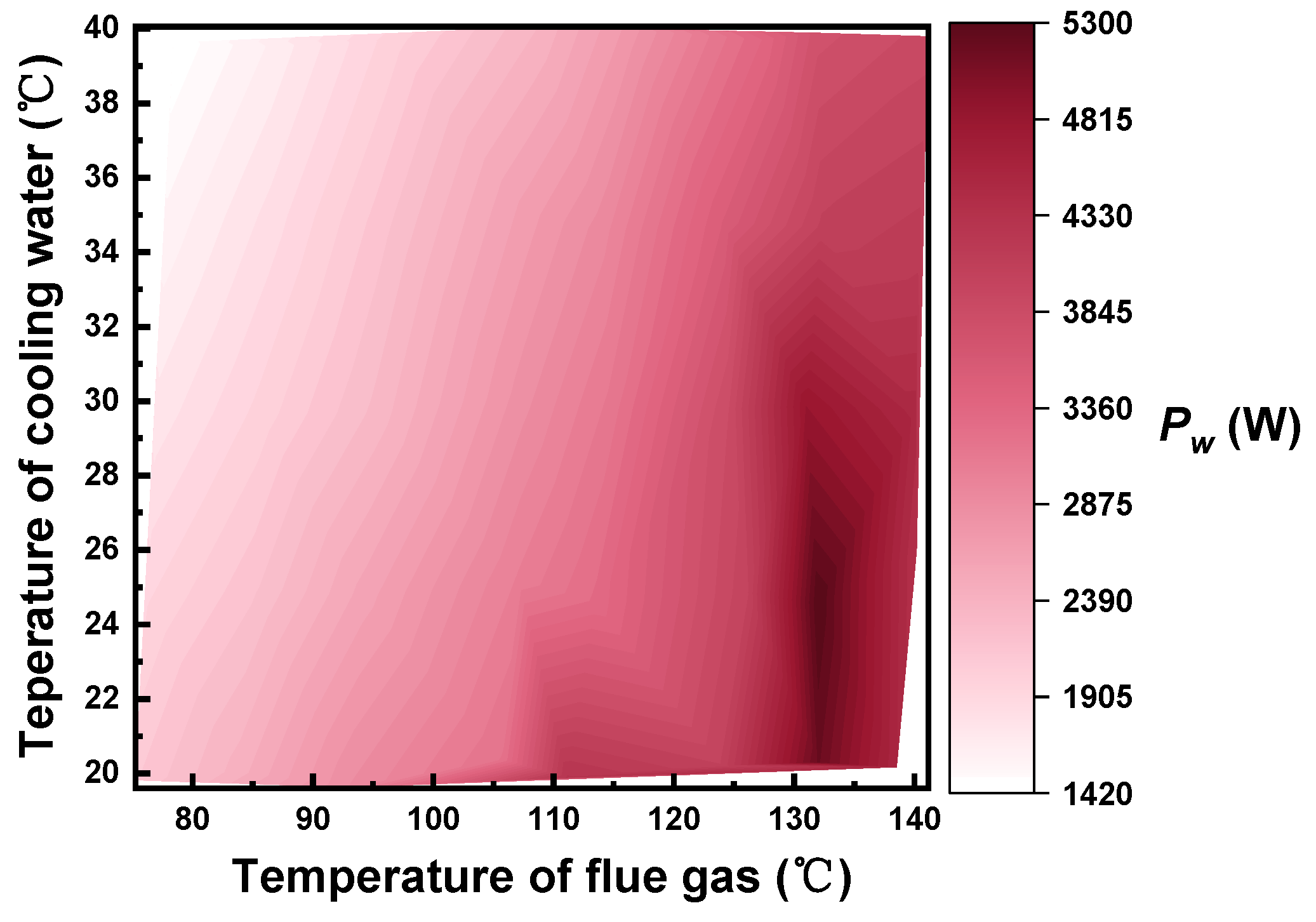
Figure 8.
Conversion efficiency of the TEG module under varying experiment conditions.


Table 1.
Parameters of the experimental test stand.
| Flue Size | Flue Gas Temperature | Flue Gas Velocity | Cooling Water Temperature | Cooling Water Flow |
|---|---|---|---|---|
| 605 mm (L) × 506 mm (W) × 435 mm (H) | 20–200 °C | 0–3.4 m/s | 5–40 °C | 0–0.743 m3/h |
Table 2.
The simulation results of the impact of fin structures on the temperature difference on TEM.
Table 2.
The simulation results of the impact of fin structures on the temperature difference on TEM.
| Fin Spacing | 2 mm | 4 mm | 6 mm | 8 mm | 10 mm | |
|---|---|---|---|---|---|---|
| Fin Height | ||||||
| 25 mm | 59 °C | 56 °C | 51 °C | 45 °C | 41 °C | |
| 35 mm | 66 °C | 63 °C | 57 °C | 52 °C | 47 °C | |
| 45 mm | 72 °C | 69 °C | 64 °C | 58 °C | 53 °C | |
| 55 mm | 76 °C | 73 °C | 69 °C | 63 °C | 56 °C | |
Table 3.
The dimensional parameters of a TEG unit.
| Specifications of Single TEG Unit | 495 mm × 100 mm × 130 mm | ||||
|---|---|---|---|---|---|
| Heat Collection Structure | TEM | Water Cooling Plate | |||
| Specifications | 450 mm × 100 mm × 45 mm | Specifications | 25 mm × 25 mm × 3.5 mm | Specifications | 470 mm × 70 mm × 12 mm |
| Number | 2 | Number | 40 | Number | 1 |
Disclaimer/Publisher’s Note: The statements, opinions and data contained in all publications are solely those of the individual author(s) and contributor(s) and not of MDPI and/or the editor(s). MDPI and/or the editor(s) disclaim responsibility for any injury to people or property resulting from any ideas, methods, instructions or products referred to in the content. |
© 2024 by the authors. Licensee MDPI, Basel, Switzerland. This article is an open access article distributed under the terms and conditions of the Creative Commons Attribution (CC BY) license (https://creativecommons.org/licenses/by/4.0/).
Share and Cite
MDPI and ACS Style
Gu, Z.; He, S.; Li, X.; Sun, P.; Wu, J.; Hu, H.; Zhang, Q.; Jiang, J. Hundred-Watt Implantable TEG Module for Large-Scale Exhaust Gas Waste Heat Recovery. Energies 2024, 17, 665. https://doi.org/10.3390/en17030665
AMA Style
Gu Z, He S, Li X, Sun P, Wu J, Hu H, Zhang Q, Jiang J. Hundred-Watt Implantable TEG Module for Large-Scale Exhaust Gas Waste Heat Recovery. Energies. 2024; 17(3):665. https://doi.org/10.3390/en17030665
Chicago/Turabian StyleGu, Zhien, Shi He, Xiang Li, Peng Sun, Jiehua Wu, Haoyang Hu, Qiang Zhang, and Jun Jiang. 2024. "Hundred-Watt Implantable TEG Module for Large-Scale Exhaust Gas Waste Heat Recovery" Energies 17, no. 3: 665. https://doi.org/10.3390/en17030665
Note that from the first issue of 2016, this journal uses article numbers instead of page numbers. See further details here.