
Research on Wellbore Stability in Deepwater Hydrate-Bearing Formations during Drilling
College of Safety and Ocean Engineering, China University of Petroleum, Beijing 102200, China
*
Author to whom correspondence should be addressed.
Energies 2024, 17(4), 823; https://doi.org/10.3390/en17040823
Submission received: 22 December 2023
/
Revised: 16 January 2024
/
Accepted: 30 January 2024
/
Published: 9 February 2024
(This article belongs to the Special Issue New Progress in Unconventional Oil and Gas Development)
Abstract
:Marine gas hydrate formations are characterized by considerable water depth, shallow subsea burial, loose strata, and low formation temperatures. Drilling in such formations is highly susceptible to hydrate dissociation, leading to gas invasion, wellbore instability, reservoir subsidence, and sand production, posing significant safety challenges. While previous studies have extensively explored multiphase flow dynamics between the formation and the wellbore during conventional oil and gas drilling, a clear understanding of wellbore stability under the unique conditions of gas hydrate formation drilling remains elusive. Considering the effect of gas hydrate decomposition on formation and reservoir frame deformation, a multi-field coupled mathematical model of seepage, heat transfer, phase transformation, and deformation of near-wellbore gas hydrate formation during drilling is established in this paper. Based on the well logging data of gas hydrate formation at SH2 station in the Shenhu Sea area, the finite element method is used to simulate the drilling conditions of 0.1 MPa differential pressure underbalance drilling with a borehole opening for 36 h. The study results demonstrate a significant tendency for wellbore instability during the drilling process in natural gas hydrate formations, largely due to the decomposition of hydrates. Failure along the minimum principal stress direction in the wellbore wall begins to manifest at around 24.55 h. This is accompanied by an increased displacement velocity of the wellbore wall towards the well axis in the maximum principal stress direction. By 28.07 h, plastic failure is observed around the entire circumference of the well, leading to wellbore collapse at 34.57 h. Throughout this process, the hydrate decomposition extends approximately 0.55 m, predominantly driven by temperature propagation. When hydrate decomposition is taken into account, the maximum equivalent plastic strain in the wellbore wall is found to increase by a factor of 2.1 compared to scenarios where it is not considered. These findings provide crucial insights for enhancing the safety of drilling operations in hydrate-bearing formations.
1. Introduction
Given the substantial increase in global energy demand, the exploration and development of alternative energy sources has become critical and urgent. Among them, gas hydrates stand out as a particularly promising candidate. Natural gas hydrates are ice-like solid crystalline substances formed when organic gases (methane, ethane, and propane) from biological sources and/or heat sources are fixed in a caged structure of water molecules under high pressure and low temperature conditions within the hydrate stability zone [1]. This resource is abundant in marine sediments and offers a potentially significant contribution to future energy substitution [2].
The exploitation of marine natural gas hydrate is inseparable from drilling, but the deformation resistance of the formation containing natural gas hydrate is weak [3]. The decomposition of gas hydrates will further reduce the mechanical strength of the formation and lead to wellbore instability. This can easily lead to a series of drilling safety problems, such as blowouts, leaks, and reservoir subsidence [4]. Therefore, maintaining wellbore stability is one of the major challenges of drilling in offshore gas hydrate formations [5]. The above challenges seriously restrict the exploration and exploitation of marine natural gas hydrate resources. Therefore, in recent years, domestic and foreign experts and scholars have conducted a series of experiments and simulation studies on wellbore stability during the drilling of natural gas hydrate formation.
Studies have shown that the properties of natural gas hydrate are very similar to those of ice [6]. The study of the phase equilibrium of hydrates is the basis of related research on hydrates, which was started earlier, and some formulas have been widely used [7,8]. In recent years, with the in-depth discussion of the problem, new developments have been made in the study of the phase equilibrium of some substances, including the study of the phase equilibrium of hydrates [9,10,11,12]. In the study of the wellbore stability of hydrate formation, a coupling model considering the decomposition of natural gas hydrate has been established on ABAQUS, COMSOL Multiphysics, and MATLAB. The physical field of some of these models is relatively complete, taking into account factors such as drilling fluid intrusion and reservoir strength change [5,13,14]. Moreover, some scholars have pointed out that the decomposition of methane hydrate has a significant impact on reservoir strength [15], and the high ground stress difference of hydrate formation aggravates the risk of wellbore instability [16]. Some scholars have further explored the effect of methane hydrate inhibitors on inhibiting wellbore instability [17]. Existing studies generally believe that the decomposition of natural gas hydrate will increase the risk of wellbore instability, but the specific process of wellbore instability needs to be further studied.
Based on the existing geological data of hydrate reservoir and the physical model applicable to the geological data, combined with the classical phase equilibrium model, a finite element model of a heat–fluid–solid coupling wellbore considering the decomposition of methane hydrate is established. Through calculation, the key links and phenomena of the sequence process of hydrate decomposition—reservoir strength weakening—wellbore instability are quantitatively analyzed, and the influence of hydrate decomposition on the drilling safety of hydrate formation is summarized, hoping to provide reference for related operations.
2. Numerical Model
To more accurately simulate the variations of physical parameters in hydrate reservoirs during drilling, the open-hole wellbore stability model established in this study includes the following assumptions:
- (1)
- The deformation of the reservoir conforms to the small strain assumption of elastic mechanics;
- (2)
- The hydrate reservoir at the selected formation depth is considered a homogeneous material, disregarding differences in specific heat capacity and thermal conductivity between fluids and the rock matrix;
- (3)
- The impact of secondary hydrate formation due to localized temperature reduction from hydrate endothermic reactions on reservoir properties is neglected;
- (4)
- When hydrates decompose due to temperature and pressure changes, only their phase changes are considered, ignoring potential movement relative to the rock skeleton;
- (5)
- The influence of wellbore collapse on the temperature and seepage fields is disregarded.
2.1. Key Control Equations for the Coupled THMC Model
2.1.1. Kinetic Equations for Hydrate Decomposition
The stability of hydrates depends on specific temperature and pressure conditions, commonly referred to as the phase equilibrium conditions of hydrates. The phase equilibrium temperature in Kelvin (K) and phase equilibrium pressure in Mega Pascals (MPa) are related as follows [8]:
When the pressure and temperature within the sediment pore decrease below the equilibrium conditions, the phase equilibrium of hydrates is disrupted, initiating the decomposition process that results in the production of methane gas and water. Consequently, the solid hydrate within the sediment pore gradually transforms into liquid and gas phases. Based on the Kim–Bishnoi kinetic model for natural gas hydrate decomposition, the rate of decomposition of natural gas hydrates in a unit volume porous medium is given by [18]:
where is the decomposition surface area of the unit volume porous medium, which is related to hydrate saturation and porosity, and the calculation formula is , in 1/m [19]; represents the reaction kinetic constant in ; represents the activation energy for natural gas hydrate reactions in J/mol; R is the gas constant, with a value of approximately 8.314 joules per mole-kelvin (J/(mol·K)); represents the gas pressure within the reservoir pore space.
The process of natural gas hydrate decomposition can be represented by the chemical equation , and in most cases, N is taken as 6 [20]. The mass balance equation for the decomposition of natural gas hydrates into hydrate, gas, and water is expressed as follows:
where represents, respectively, hydrate (h), methane (g), and water (w); is the density of each phase, measured in units of.kg/m3, where the density of the gas() can be expressed as , and represents the molar mass of methane gas, which is approximately 16.04 g per mole (g/mol) [21]; represents the saturation of each phase, and the relationships between the saturation of each phase can be expressed as ; represents the porosity of the hydrate reservoir, dimensionless; stands for the reaction rates of each phase (formation or decomposition), so the relationships between the reaction rates of each phase can be expressed as .
2.1.2. Energy Conservation Equation for Hydrate Decomposition
The energy conservation equation for the decomposition of natural gas hydrates can be expressed as follows [22]:
where is the specific heat capacity of each phase (j = h, g, w, s) in ; is the enthalpy change for the decomposition reaction of natural gas hydrates and can be represented according to Masuda’s model as , where c and d are experimental regression coefficients, dimensionless. According to the research, the values for c and d are 56,599 and −16.744 , respectively. is the thermal conductivity of the reservoir; is the unit of heat absorbed from the external environment during the decomposition of hydra.
2.2. Wellbore Stability Model
2.2.1. Mechanical Model of Hydrate Deposits
In the Shenhu area of the South China Sea, the hydrate reservoirs are predominantly composed of muddy fine siltstone, characterized by weak cementation and diagenesis [23]. This composition sets them fundamentally apart in mechanical properties from sandstone-type hydrate reservoirs. The equation describing the variation of the elastic modulus, E(Sh), during the decomposition process of hydrates is as follows [24]:
where is the elastic modulus of the sand body without hydrates, in MPa; represents the effective stress experienced by the hydrate-bearing sand body.
The elastic modulus of hydrate-bearing muddy fine siltstone is not affected by changes in the hydrate saturation within the sand body, but it is influenced by the confining pressure. The relationship between the Poisson’s ratio of hydrate-bearing muddy fine siltstone and the effective stress can be expressed as [24]:
where represents the Poisson’s ratio of hydrate-bearing sediment. refers to the Poisson’s ratio under the initial stress state, dimensionless. Due to the role of hydrates in original reservoirs as fillers and cementing agents, the decomposition of hydrates can significantly affect the cementation of the reservoir, reducing the strength of the reservoir’s geotechnical properties. We established the following empirical model relating cohesion to the degree of saturation in hydrates [23]:
where represents the cohesive force, and is the cohesive force of the hydrate reservoir when the hydrate saturation is zero. and are empirical coefficients; the values are 0.0011 and 1.91, respectively [23].
2.2.2. Wellbore Yield Failure Criterion
Assuming that the strata surrounding the wellbore are homogeneous, isotropic, linear thermo-elastic porous media, it is considered that the rocks around the well are in a state of plane strain. The wellbore is now assumed to be a problem of stress concentration around a circular hole in an infinite plane. Figure 1 shows the mechanical model of a vertical wellbore where the strata are considered as linear elastic bodies. The maximum horizontal earth stress () acts at an infinite distance in the horizontal direction, and the minimum horizontal earth stress () acts at an infinite distance in the vertical direction. The pressure of the drilling fluid column (P) acts inside the wellbore, and the pore pressure of the strata acts within the formation.
In the mechanical analysis of geotechnical materials, the most commonly used shear failure criteria include the Mohr–Coulomb (M–C) strength criterion, Drucker–Prager (D–P) criterion, and Lade criterion [25]. This paper simplifies the wellbore stability model of hydrate reservoirs; employing the Mohr–Coulomb constitutive model for geotechnical materials, the expression is as follows [26]:
where represents the internal friction angle.
3. Model Construction
3.1. Numerical Method
3.1.1. Finite Element Software Secondary Development
Drilling for gas hydrates involves a coupled process of thermodynamics, hydrology, and mechanics. ABAQUS 2021 software has a good application effect in rock and soil mechanics problems. However, the built-in functional modules of ABAQUS software are not enough to solve the multi-physical field coupling problems involved in this study, especially in the simulation of phase transition decomposition of natural gas hydrate, endothermic decomposition, and the effect of decomposition on reservoir physical properties. Therefore, the simulation in this paper is based on the numerical model summarized in the above section, and the ABAQUS software is developed again. Figure 2 shows the calculation flow diagram of the USDFLD subroutine.
3.1.2. Verification of Secondary Development Subroutine
In order to verify the applicability of the USDFLD subroutine, the program was verified by referring to the experimental results of the disturbance of the hydrate reservoir by drilling fluid conducted by other scholars [27]. The experimental data of 30% hydrate saturation were selected to compare the decomposition time corresponding to the three test points in the experiment. The results showed that the maximum difference between the numerical simulation results and the experimental results was 86 min, accounting for less than six percent of the total simulation time, as shown in Figure 3. The USDFLD subroutine had sufficient accuracy for further research.
3.2. Geological Setting
The research zone, situated in the central region of the South China Sea’s northern slope, lies between the Xisha Trough and the Dongsha Archipelago. Conducted between April and June 2007, China’s inaugural expedition for drilling gas hydrates, GMGS-1, focused on this zone (as illustrated in Figure 4) [28]. The expedition involved drilling at eight locations and performing well logging, with core samples obtained from five sites. Notably, gas hydrate specimens were extracted from three sites, namely SH2, SH3, and SH7 [29,30]. This study specifically concentrates on site SH2 for wellbore stability analysis. Data from drilling and well logging reveal that gas hydrates at this site lie between 185 and 229 m below the seafloor, extending over approximately 44 m with around 40% porosity, in a region where the water depth measures 1235 m. In situ observations recorded a maximum hydrate saturation of 47%. The ambient bottom-water temperature approximates 4 degrees Celsius, coupled with a geothermal gradient of 46.9 degrees Celsius per kilometer [5].
Due to the large number of drilling operations and sufficient geological data, many scholars have carried out experimental research based on the characteristics of geological parameters in this region, and the hydrate depositional mechanics model selected in Section 2.2.1 is applicable to the muddy fine siltstone in this region. Thanks to the improvement of related research, the geological parameters of this region are selected for the study of the stability of the wall of the well in this paper.
3.3. Geometric Model Parameters and Initial Conditions
As depicted in Figure 5a, based on the drilling and logging data from the SH2 site, a schematic representation of deep-water hydrate reservoir drilling was constructed. The thickness of the hydrate reservoir is 44 m, with a wellbore radius of 0.1588 m. This simulation employed a fully coupled approach, creating a three-dimensional solid model with a thickness of 0.1 m. A significantly larger external boundary diameter was chosen, measuring 10 m, divided into 4200 C3D8RPT elements. The mesh distribution was designed to gradually densify from the boundary towards the wellbore interior. Figure 5b shows a quarter model where the internal wellbore pressure is governed by the drilling fluid hydrostatic pressure, and the external load is constituted by the reservoir pore pressure. The internal temperature of the wellbore corresponds to the drilling fluid temperature, while the external boundary reflects the initial formation temperature. Full constraints were applied at the external boundary, and during the geostress equilibrium analysis step, the internal boundary of the wellbore was fully constrained. These constraints were removed when the wellbore was opened, and the top and bottom boundaries were subjected to constraints in the z-direction for displacement and rotation. The specific parameters are detailed in Table 1.
This parameter has typical deep-water characteristics, including a larger lack of pore pressure corresponding to smaller horizontal ground stress and a smaller modulus of elasticity and cohesion of the reservoir, reflecting the loose and weak cementation characteristics of the deep-water shallow bottom layer. The model based on this parameter has good applicability for the analysis of well wall stabilization problems in deep-water shallow hydrate reservoir wellbores.
Figure 6 presents the established wellbore stability analysis model of this study, depicting the displacement distribution after geostress equilibrium calculations. The maximum displacement magnitude, observed post-geostress equilibrium, is in the range of 10−4. In geotechnical engineering, a displacement reaching 10−4 following geostress equilibrium indicates that the reservoir is free from initial displacement. Consequently, the initial geostress equilibrium results of this model are deemed adequate for subsequent computational requirements.
4. Results and Discussion
4.1. The Distribution and Evolution of Pore Pressure and Temperature after Well Opening
Figure 7 illustrates the variations in temperature and pore pressure within the hydrate reservoir at 9 and 34 h after the wellbore opening. Due to the higher temperature of the drilling fluid at the wellbore compared to the reservoir, hydrates become destabilized and decompose, generating methane and water. Under the influence of the pressure differential, methane and water migrate into the wellbore, leading to a reduction in reservoir pore pressure. As evidenced in Figure 8, after 9 h of the wellbore opening, the propagation of pore pressure reaches the outer boundary of the model, while the thermal propagation extends approximately 0.55 m. At 34 h post-opening, there is a further decline in formation pore pressure, and the thermal conduction distance is less than 1 m. At this stage, drilling fluid invades the reservoir, and with the decomposition of hydrates, the effective stress and strength of the hydrate-bearing sediments near the wellbore decrease. A comprehensive analysis reveals that at a pressure differential of 0.1 MPa, hydrate decomposition is predominantly governed by the thermal field. However, as the propagation distance increases, the volume of the heat-storing formation multiplies, significantly elevating the heat required for raising reservoir temperature, thereby drastically slowing down the rate of thermal conduction. Consequently, the impact of hydrate decomposition on wellbore stability is more pronounced within the first 10 h of wellbore opening. As the rate of temperature transmission slows down in the later stages, the advancement of the hydrate decomposition front becomes less distinct, and the rate at which hydrate decomposition undermines the mechanical integrity of the wellbore also weakens.
4.2. The Distribution and Evolution of Reservoir Mechanical Properties after Well Opening
Figure 9 represents the variations in hydrate saturation within the hydrate reservoir at 9 and 34 h after the wellbore opening. Based on the changes in hydrate saturation depicted in Figure 10, it is evident that the decomposition of hydrates is driven by high-temperature or low-pressure conditions. Consequently, hydrate decomposition predominantly occurs in the vicinity of the wellbore. Within 9 h of opening the wellbore, the decomposition radius reaches 0.4 m and gradually extends outward from the wellbore. The decomposition radius expands to 0.48 m at the 17th hour, 0.52 m at the 25th hour, and finally reaches 0.55 m by the 34th hour, with only a marginal increase of 0.03 m in the last 15 days. As time progresses, the extension of the hydrate decomposition radius tends to diminish, indicating the presence of a critical range for hydrate decomposition during the drilling process. This phenomenon arises due to the limited impact range on reservoir temperature and pore pressure after opening the wellbore. The distribution of Mises stress in the reservoir is closely associated with the decomposition of hydrates. Following the decomposition of hydrates, the strength within the decomposition zone rapidly decreases, leading to a corresponding reduction in effective stress. Greater levels of decomposition are associated with an increased likelihood of localized stress concentration. Consequently, in the vicinity of the wellbore, stress gradually increases as hydrates decompose. According to the stress evolution curve, it is observed that a turning point occurs in the stress curve after 34 h of wellbore opening, indicating the occurrence of damage within a range of approximately 0.55 m around the wellbore. Therefore, it is advisable to consider increasing the drilling speed to reduce drilling time and mitigate the risk of wellbore instability.
Figure 11 shows the distribution of reservoir elastic modulus, cohesion, and equivalent plastic strain 36 h after the well opening. When considering hydrate decomposition, the maximum equivalent plastic strains after 36 h of well exposure are 0.4792 and 0.2014, with a difference of 0.2778, which is 2.1 times the maximum value of equivalent plastic strain calculated without considering hydrate decomposition. This is due to the significant weakening of the reservoir strength caused by hydrate decomposition, especially the numerical value of the elastic modulus, which is greatly affected by hydrate decomposition. After 36 h, the elastic modulus value of most parts of the formation is 195.7 MPa. Due to the impact of hydrate decomposition, the minimum elastic modulus around the well drops to 36.07 MPa. Under the influence of stress concentration at the well wall and without considering hydrate decomposition, the well wall is further compacted, slightly increasing its elastic modulus. Comparing scenarios with and without hydrate decomposition, the maximum difference in elastic modulus at the well wall is 159.63 MPa, which is 4.4 times the elastic modulus in the completely decomposed hydrate area, showing the significant impact of hydrate decomposition on the reservoir's elastic modulus. In contrast, the impact of hydrate decomposition on the reservoir's cohesion is relatively small. Considering hydrate decomposition, the combined effect of reduced hydrate saturation and pore pressure leads to an increase in reservoir porosity, thereby reducing the cohesion around the well by 0.0123 MPa. In areas unaffected by hydrate decomposition, the cohesion remains at 0.1177 MPa. For scenarios not considering hydrate decomposition, the porosity around the well decreases due to compaction, but the impact on cohesion is minimal, with the overall model’s cohesion essentially remaining at 0.1177 MPa.
4.3. Analysis of Wellbore Stability after Well Opening
Figure 12 shows the distribution of plastic strain and Mises stress at the moment of the occurrence of well wall instability, and analyzed in conjunction with Figure 13, the damage of the well wall occurs in the direction of the minimum principal stress of the well wall after the borehole is opened for 24.55 h. The damage of the well wall occurs in the direction of the minimum principal stress of the well wall. From Figure 10, it can be seen that at the ninth hour of the borehole opening, the hydrate in the reservoir has decomposed about 0.3 m, corresponding to the strength of the reservoir, which has been substantially weakened, but the destabilization of the well wall occurs 15 h after the decomposition of the hydrate. This is due to the fact that the dominant factors of the destabilization of the well wall are the geopathic stresses and non-homogeneous distribution of the geopathic stresses. If the value of the horizontal geopathic stresses is bigger or the distribution is more non-homogeneous, it will result in the destruction of the wall at an earlier time.
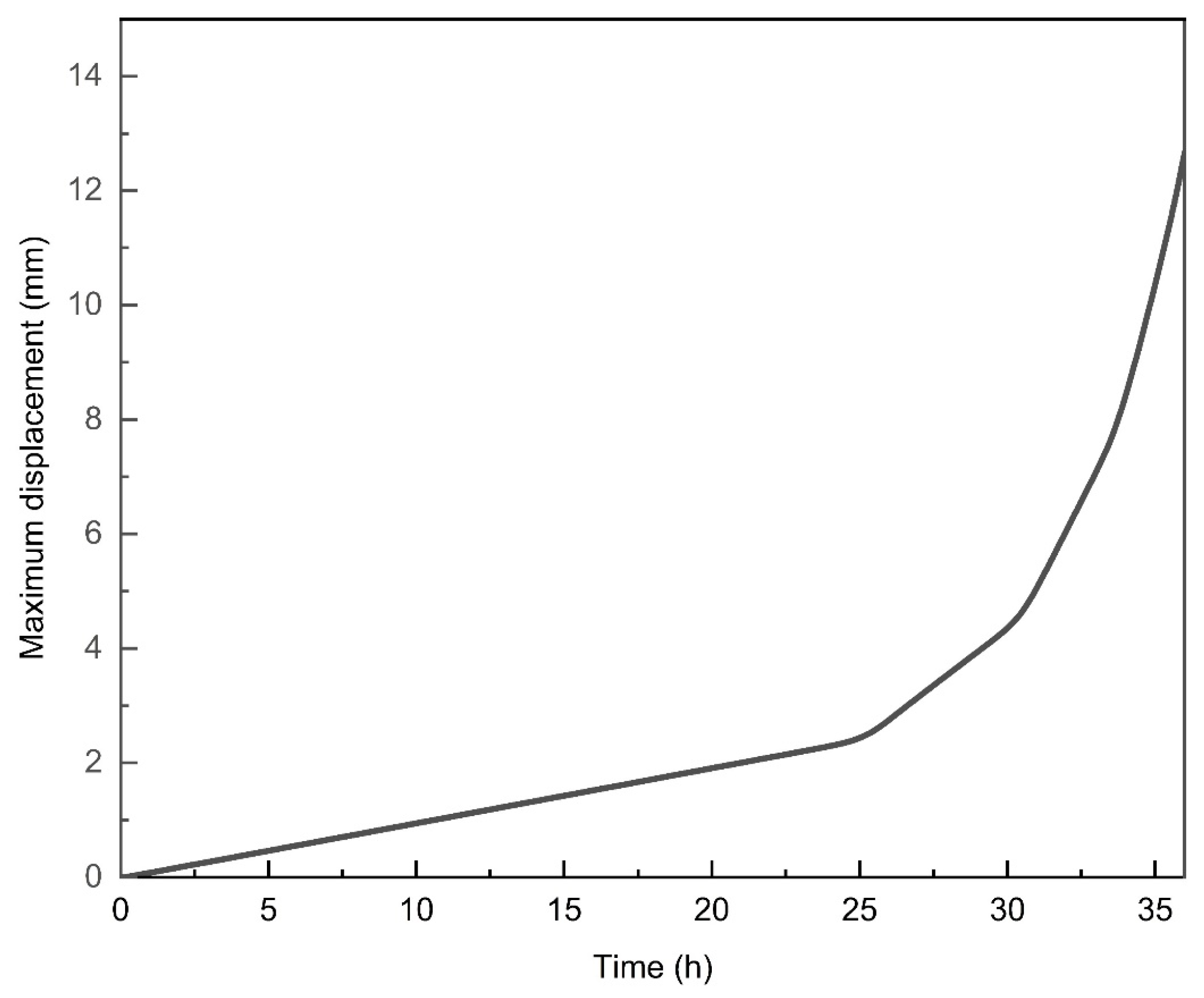
As can be seen from Figure 13, the maximum equivalent plastic strain of the well wall increases rapidly with the increase of the wellbore immersion time. At 34.57 h, well collapse occurs. The gray area of equivalent plastic strain is the well wall collapse area, which is mainly located in the direction of the minimum principal stress. From Figure 11b, it can be seen that the maximum stress value at the selected study point before the damage occurs is 2.724 MPa. When the well wall collapses, the stress in the damage zone decreases and the damage zone moves inward.
Figure 14 shows the curve of displacement over time in the direction of the maximum principal stress. When the wellbore is drilled open for 24 h, i.e., when damage occurs in the direction of the minimum principal stress of the wellbore wall, there is a trend of accelerated deformation in the direction of the maximum principal stress. After the wellbore has been open for 28 h, plastic damage extends to the entire circumference of the well. From the above analysis, it can be concluded that wellbore collapse does not occur in the early stages of drilling. However, when the wellbore is exposed for a longer time, there is a risk of wellbore wall instability. Therefore, this risk can be reduced by appropriately speeding up the operation to decrease the working time.
5. Conclusions
Taking into account the impact of hydrate decomposition on the strength of hydrate reservoirs, this study utilized the ABAQUS finite element simulation software. Dynamic property changes of the hydrate reservoir were encoded into a USDFLD subroutine, which is accessible by ABAQUS. Additionally, a HETVAL subroutine was developed to simulate the endothermic process of hydrate decomposition, incorporating the effects of hydrate decomposition on the reservoir’s thermal field. A finite element model of wellbore stability in the hydrate layer was established. Through detailed analysis and research, the following conclusions are drawn:
- (1)
- During the drilling process, wellbore instability does not occur abruptly following wellbore opening, but rather evolves as a result of redistributed geostresses. This instability initiates when the concentrated forces acting near the wellbore exceed the strength limits of the wellbore rock, leading to the onset of damage. Initially, this damage manifests as sand production from the reservoir, followed by an accelerated rate of wellbore degradation. The affected area expands longitudinally and laterally from the initial failure points. Over time, as the wellbore is exposed to the formation fluids, wellbore collapse occurs. During drilling operations, increasing the rate of mechanical drilling can be an effective strategy to swiftly complete the drilling process and thus mitigate operational disruptions caused by wellbore collapse. At the same time, it is recommended to use cooling equipment to reduce the drilling fluid temperature.
- (2)
- When equivalent plastic strain appears in the direction of minimum principal stress, although plastic strain has not yet occurred in the direction of maximum principal stress, there is an accelerated displacement change along the well axis.
- (3)
- The decomposition of hydrates is strongly correlated with the instability of wellbore walls. The breakdown of hydrates significantly reduces the elastic modulus of the reservoir, while having a relatively minor impact on the elastic parameters.
- (4)
- For underbalanced drilling operations with a pressure differential of 0.1 MPa, temperature plays a dominant role in the decomposition of hydrates during the drilling process. In the early stages of drilling, hydrate decomposition occurs rapidly. However, as the rate of heat conduction slows down, the advancement of the hydrate decomposition front also decelerates.
- (5)
- In actual drilling operations, drilling fluid will form mud cake on the well wall, which is crucial for the protection of the well wall. The influence of drilling fluid properties on the stability of the well wall is not the focus of this paper, but it is suggested that the impact of mud cake formation on the stability of the well wall could be considered in the future.
Author Contributions
Conceptualization, T.S.; Methodology, Z.W.; Investigation, J.Y. All authors have read and agreed to the published version of the manuscript.
Funding
This research is supported by the National Natural Science Foundation of China (Grant No.52274018), National Natural Science Foundation of China (U20B6005).
Data Availability Statement
All data generated or analyzed during this study are included in this published article.
Conflicts of Interest
The authors declare no conflict of interest.
References
- Su, Z.; Huang, L.; Wu, N.; Yang, S. Effect of thermal stimulation on gas production from hydrate deposits in Shenhu area of the South China Sea. Sci. China Earth Sci. 2013, 56, 601–610. [Google Scholar] [CrossRef]
- Sloan, E.D.; Koh, C.A. Clathrate Hydrates of Natural Gases; CRC Press: Boca Raton, FL, USA, 1990. [Google Scholar]
- Yu, L.; Zhang, L.; Zhang, R.; Ren, S. Assessment of natural gas production from hydrate-bearing sediments with unconsolidated argillaceous siltstones via a controlled sandout method. Energy 2018, 160, 654–667. [Google Scholar] [CrossRef]
- Zhao, X.; Qiu, Z.; Wang, M.; Xu, J.; Huang, W. Experimental investigation of the effect of drilling fluid on wellbore stability in shallow unconsolidated formations in deep water. J. Pet. Sci. Eng. 2019, 175, 595–603. [Google Scholar] [CrossRef]
- Sun, J.; Ning, F.; Lei, H.; Gai, X.; Sánchez, M.; Lu, J.; Li, Y.; Liu, L.; Liu, C.; Wu, N.; et al. Wellbore stability analysis during drilling through marine gas hydrate-bearing sediments in Shenhu area: A case study. J. Pet. Sci. Eng. 2018, 170, 345–367. [Google Scholar] [CrossRef]
- Li, Z.; Gan, B.; Li, Z.; Zhang, H.; Wang, D.; Zhang, Y.; Wang, Y. Kinetic mechanisms of methane hydrate replacement and carbon dioxide hydrate reorganization. Chem. Eng. J. 2023, 477, 146973. [Google Scholar] [CrossRef]
- Kamath, V.A.; Mutallk, P.N.; Sira, J.H.; Patil, S.L. Experimental Study of Brine Injection and Depressurization Methods for Dissociation of Gas Hydrates. SPE Form. Eval. 1991, 6, 477–484. [Google Scholar] [CrossRef]
- Dickens, G.R.; Quinby-Hunt, M.S. Methane hydrate stability in seawater. Geophys. Res. Lett. 1994, 21, 2115–2118. [Google Scholar] [CrossRef]
- Tao, Z.; Yanhui, Z.; Klemens, K.; Abdallah; Shuyu, S.; Ibrahim, H. Deep learning–assisted phase equilibrium analysis for producing natural hydrogen. Int. J. Hydrogen Energy 2024, 50, 473–486. [Google Scholar] [CrossRef]
- Tao, Z.; Yanhui, Z.; Klemens, K.; Abdallah; Shuyu, S.; Ibrahim, H. Phase equilibrium in the hydrogen energy chain. Fuel 2022, 328, 125324. [Google Scholar] [CrossRef]
- Yanyan, H.; Jing-Chun, F.; Yan, X.; Yi, W.; Pian, L.; Mingrui, Z. Phase equilibrium characteristics of natural gas hydrate formation at the deep-water environment of “Haima” cold seep. Energy Rep. 2022, 8, 5501–5509. [Google Scholar] [CrossRef]
- Zheng, L.; Litao, C.; Zhiyuan, W.; Yonghai, G.; Jintang, W.; Changhong, Y.; Baojiang, S. Hydrate phase equilibria in natural sediments: Inhibition mechanism and NMR-based prediction method. Chem. Eng. J. 2023, 452, 139447. [Google Scholar] [CrossRef]
- Liao, Y.; Wang, Z.; Chao, M.; Sun, X.; Wang, J.; Zhou, B.; Sun, B. Coupled wellbore–reservoir heat and mass transfer model for horizontal drilling through hydrate reservoir and application in wellbore stability analysis. J. Nat. Gas Sci. Eng. 2021, 95, 104216. [Google Scholar] [CrossRef]
- Li, Y.; Cheng, Y.-F.; Yan, C.-L.; Wang, Z.-Y.; Song, L.-F. Effects of creep characteristics of natural gas hydrate-bearing sediments on wellbore stability. Pet. Sci. 2022, 19, 220–233. [Google Scholar] [CrossRef]
- Hu, T.; Wang, H.N.; Jiang, M.J. Analytical approach for the fast estimation of time-dependent wellbore stability during drilling in methane hydrate-bearing sediment. J. Nat. Gas Sci. Eng. 2022, 99, 104422. [Google Scholar] [CrossRef]
- Li, J.; Zhang, Y.; Di, S.; Lin, L.; Zhou, Y. Research on hydrate-bearing reservoir deformation and wellbore wall stability during natural gas hydrate exploitation. Geomech. Energy Environ. 2023, 34, 100458. [Google Scholar] [CrossRef]
- Shao, Z.; Wang, J.; Zhou, M.; Wang, E.; Lv, K.; Wang, Z.; Huang, X.; Wang, R.; Lu, C.; Sun, J. Role of chemical cementation and hydration inhibition on wellbore stability in hydrate bearing sediment: Experimental and molecular dynamics simulation studies. J. Nat. Gas Sci. Eng. 2022, 104, 104619. [Google Scholar] [CrossRef]
- Kim, H.C.; Bishnoi, P.R.; Heidemann, R.A.; Rizvi, S.S.H. Kinetics of methane hydrate decomposition. Chem. Eng. Sci. 1987, 42, 1645–1653. [Google Scholar] [CrossRef]
- Yin, Z.; Moridis, G.; Chong, Z.R.; Tan, H.K.; Linga, P. Numerical analysis of experimental studies of methane hydrate dissociation induced by depressurization in a sandy porous medium. Appl. Energy 2018, 230, 444–459. [Google Scholar] [CrossRef]
- Jiang, Y.; Ma, X.; Luan, H.; Liang, W.; Yan, P.; Song, W.; Shan, Q. Numerical simulation on the evolution of physical and mechanical characteristics of natural gas hydrate reservoir during depressurization production. J. Nat. Gas Sci. Eng. 2022, 108, 104803. [Google Scholar] [CrossRef]
- Li, J.; Yu, B. Chapter One—Gas properties, fundamental equations of state and phase relationships. In Sustainable Natural Gas Reservoir and Production Engineering; Wood, D.A., Cai, J., Eds.; Gulf Professional Publishing: Oxford, UK, 2022; Volume 1, pp. 1–28. [Google Scholar]
- Liang, W.; Zhao, T.-b.; Qiu, Y.; Wang, X. Fully Coupled Numerical Model and Its Application in Natural Gas Hydrate Reservoir. Energy Fuels 2021, 35, 2048–2063. [Google Scholar] [CrossRef]
- Miyazaki, K.; Yamaguchi, T.; Sakamoto, Y.; Tenma, N.; Ogata, Y.; Aoki, K. Effect of Confining Pressure on Mechanical Properties of Sediment Containing Synthetic Methane Hydrate. J. MMIJ 2010, 126, 408–417. [Google Scholar] [CrossRef]
- Li, Q.; Cheng, Y.; Li, Q.; Ansari, U.; Liu, Y.; Yan, C.; Lei, C. Development and verification of the comprehensive model for physical properties of hydrate sediment. Arab. J. Geosci. 2018, 11, 325. [Google Scholar] [CrossRef]
- Labuz, J.F.; Zang, A. Mohr–Coulomb Failure Criterion. Rock Mech. Rock Eng. 2012, 45, 975–979. [Google Scholar] [CrossRef]
- Van Genuchten, M.T. A closed-form equation for predicting the hydraulic conductivity of unsaturated soils. Soil Sci. Soc. Am. J. 1980, 44, 892–898. [Google Scholar] [CrossRef]
- Huaiwen, Z.; Yuanfang, C.; Jihui, S.; Lingdong, L.; Menglai, L.; Xiuting, H.; Chuanliang, Y. Experimental study of water-based drilling fluid disturbance on natural gas hydrate-bearing sediments. J. Nat. Gas Sci. Eng. 2017, 47, 1–10. [Google Scholar] [CrossRef]
- Haiqi, Z.; Shengxiong, Y.; Wu, N.; Xin, S.; Holland, M.; Schultheiss, P.; Kelly, R.; Heather, B.; Gary, H. Successful and surprising results for China’s first gas hydrate drilling expedition. Fire Ice Gas Hydrate News Lett. 2007, 7, 6–9. [Google Scholar]
- Yang, S.; Zhang, H.; Wu, N.; Su, X.; Schultheiss, P.; Holland, M.; Zhang, G.; Liang, J.; Lu, J.; Rose, K. High concentration hydrate in disseminated forms obtained in Shenhu Area, North Slope of South China Sea. In Proceedings of the 6th International Conference on Gas Hydrates (ICGH 2008), Vancouver, BC, Canada, 6–10 July 2008. [Google Scholar]
- Ye, J.-L.; Qin, X.-W.; Xie, W.-W.; Lu, H.-L.; Ma, B.-J.; Qiu, H.-J.; Liang, J.-Q.; Lu, J.-A.; Kuang, Z.-G.; Lu, C.; et al. The second natural gas hydrate production test in the South China Sea. China Geol. 2020, 3, 197–209. [Google Scholar] [CrossRef]
Figure 1.
Stress state of the well wall.
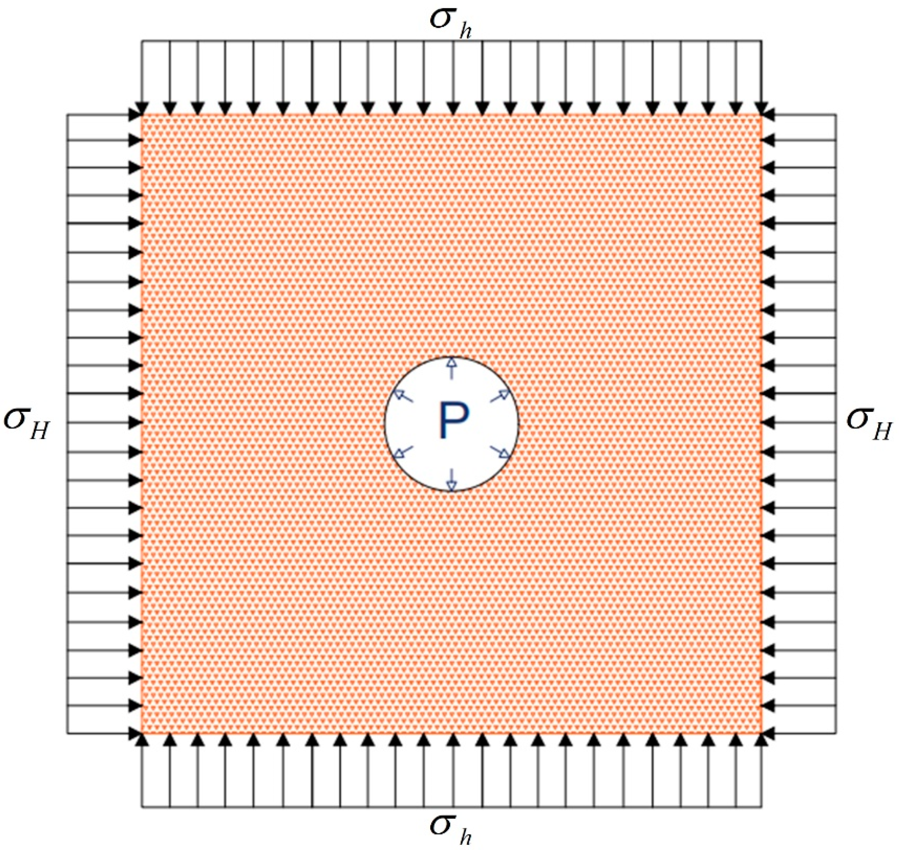
Figure 2.
USDFLD subroutine calculation flowchart.
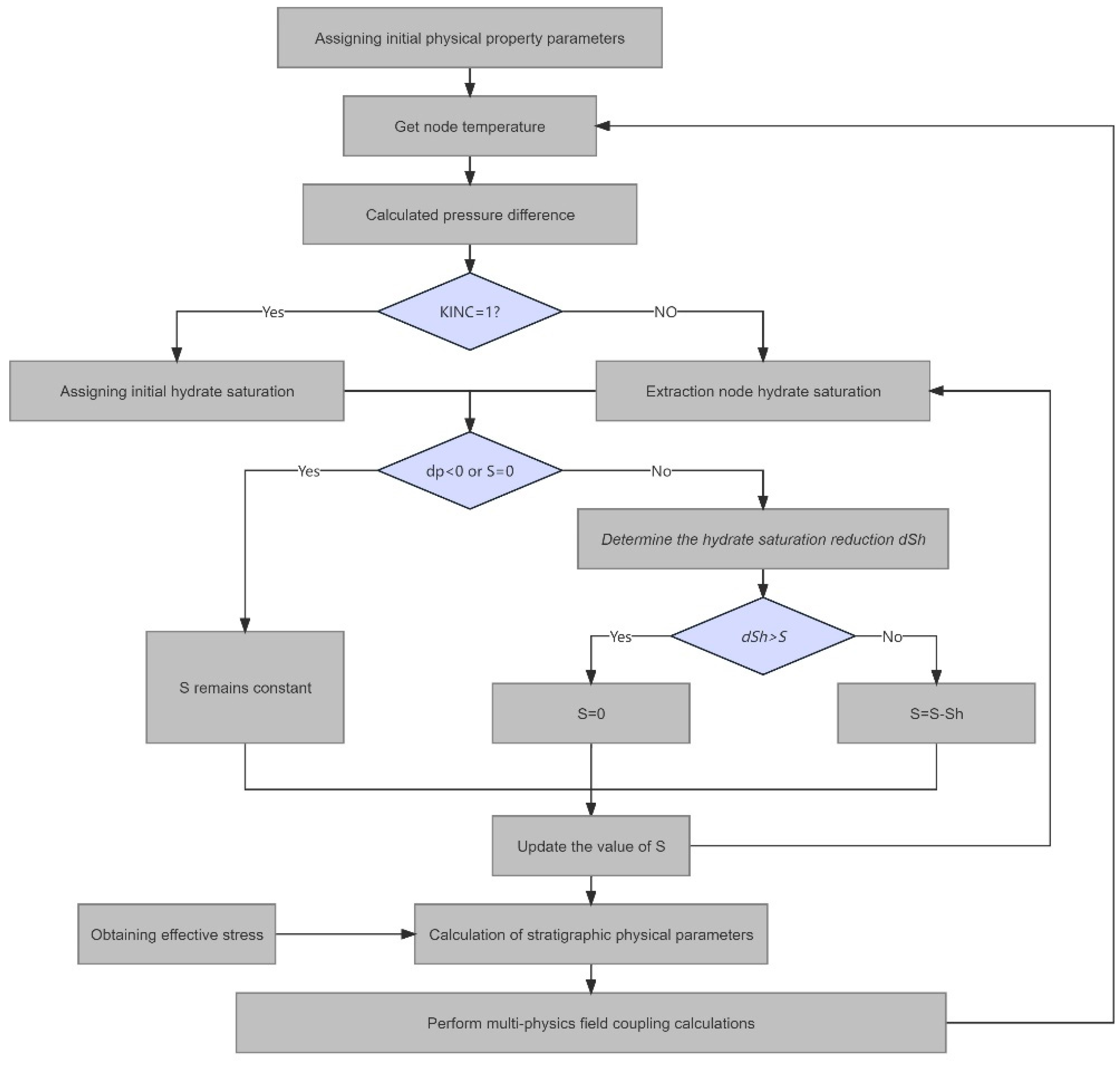
Figure 3.
Comparison between simulation and experimental results of dissociation front.
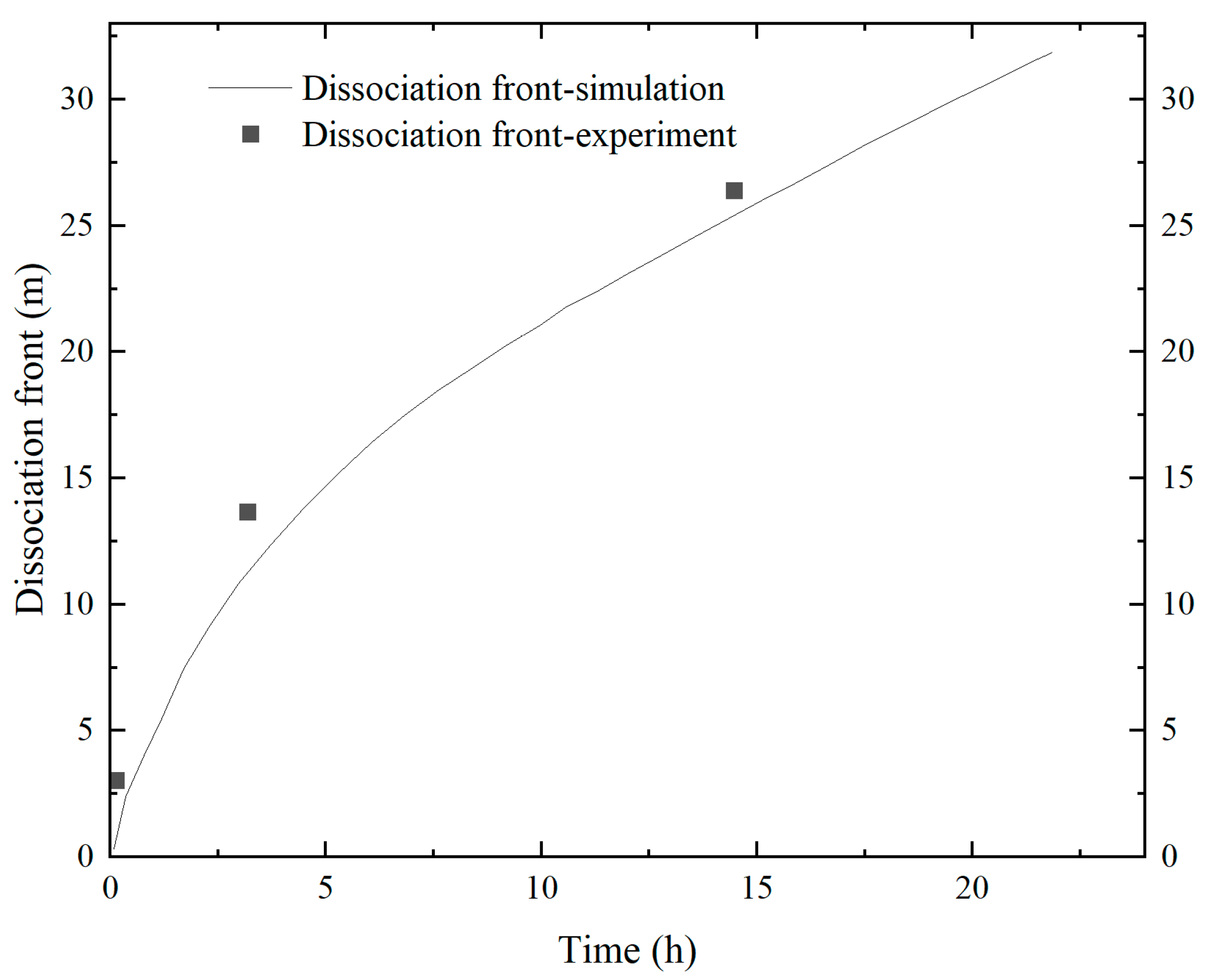
Figure 4.
Positioning of the GMGS-1 in the South China Sea.
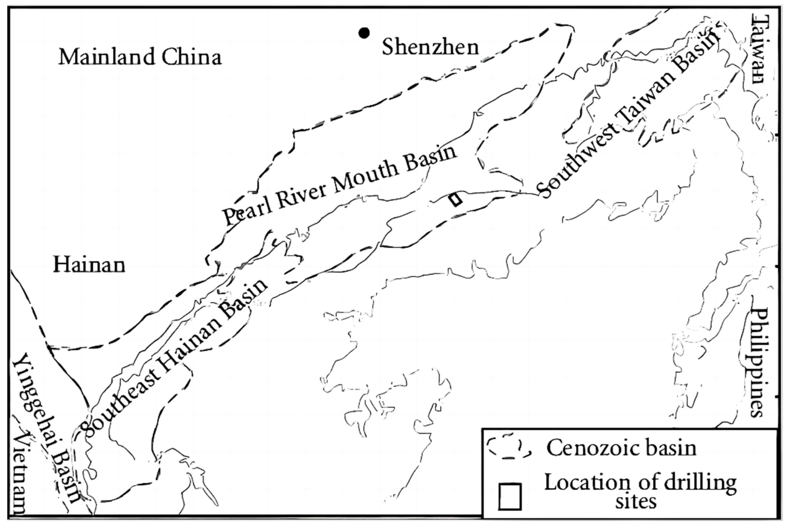
Figure 5.
(a)—Schematic diagram of the a-GMGS-1 project’s SH2 drilling through the hydrate reservoir; (b)—wellbore stability analysis model.
Figure 5.
(a)—Schematic diagram of the a-GMGS-1 project’s SH2 drilling through the hydrate reservoir; (b)—wellbore stability analysis model.
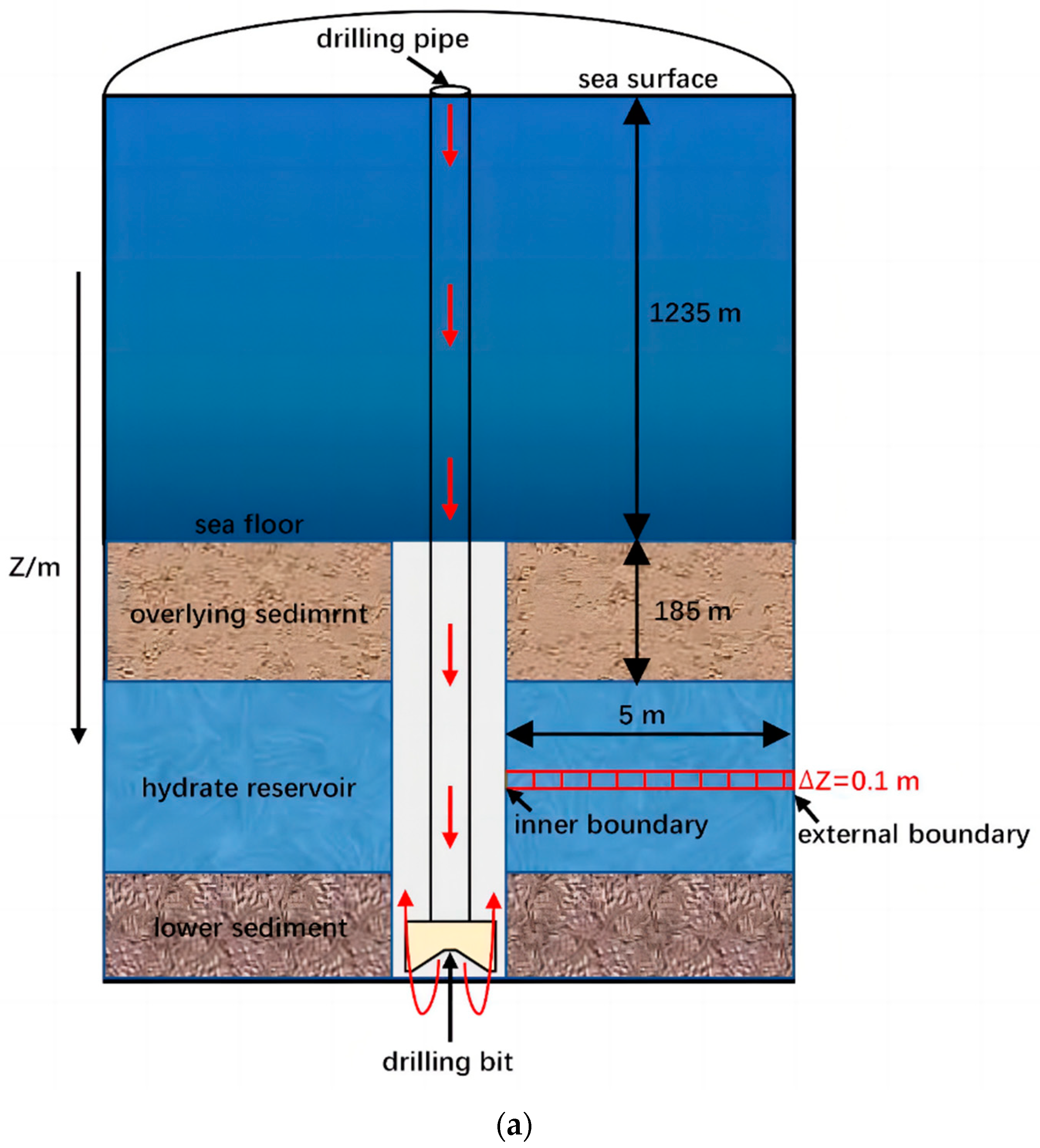
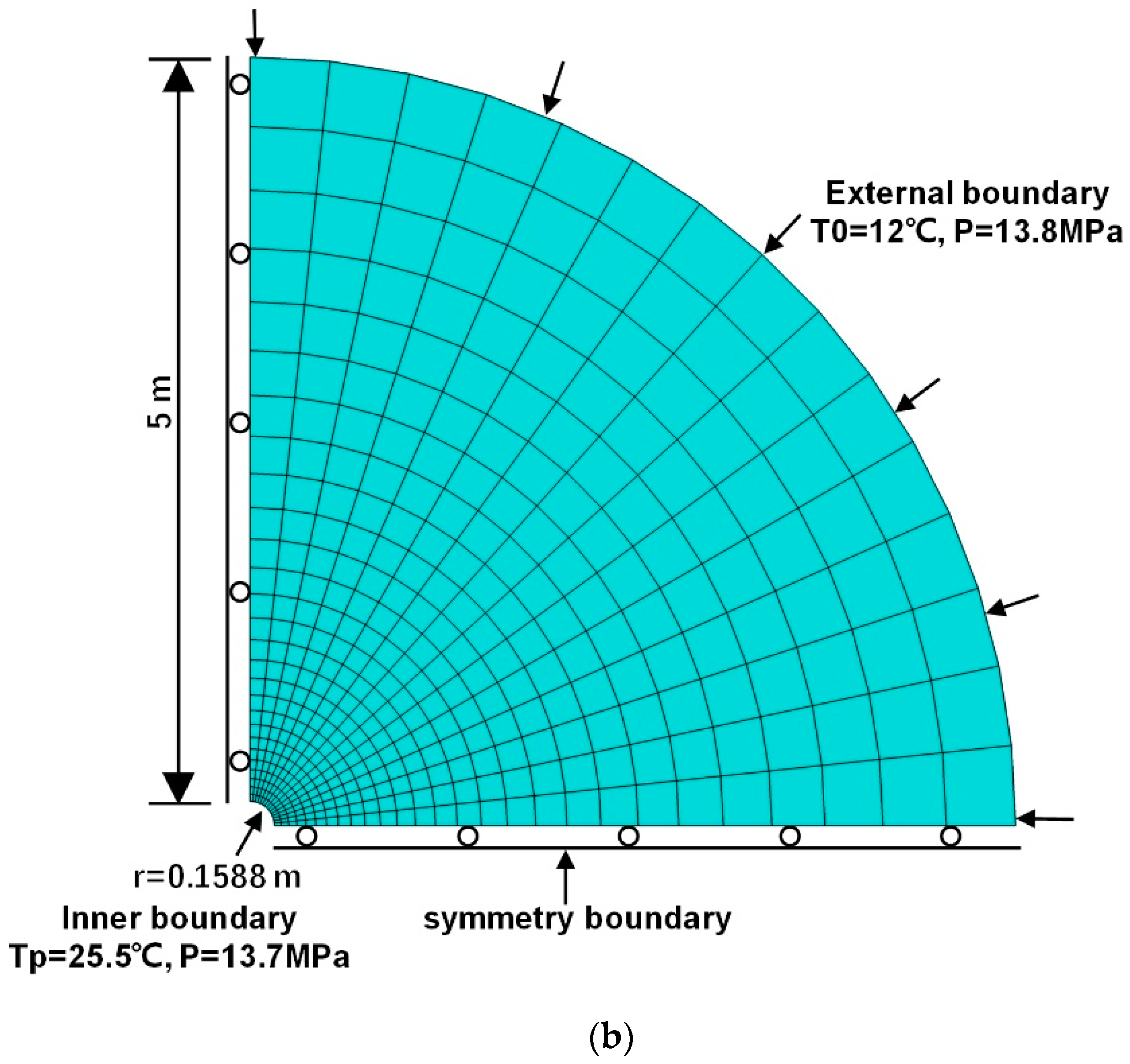
Figure 6.
Geostress equilibrium results.
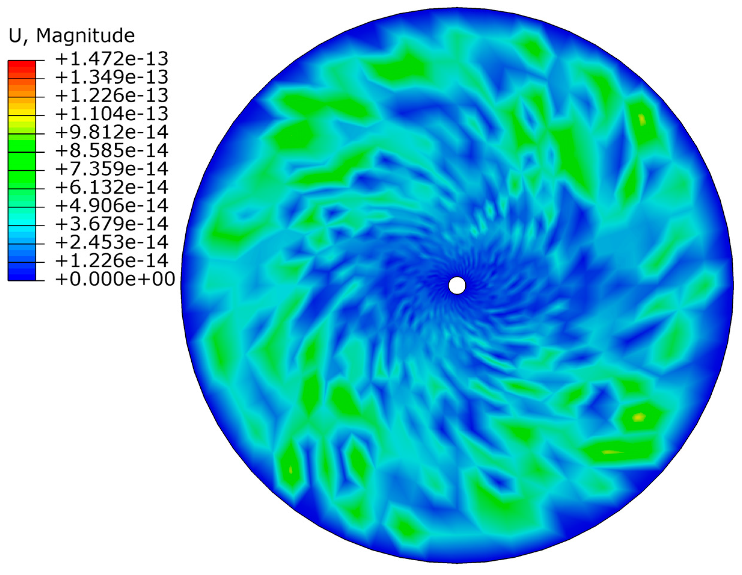
Figure 7.
Changes in parameters after wellbore opening; (a)—variation in temperature; (b)—variation in pore pressure.
Figure 7.
Changes in parameters after wellbore opening; (a)—variation in temperature; (b)—variation in pore pressure.

Figure 8.
Distribution of temperature and pore pressure along the direction of maximum principal stress.
Figure 8.
Distribution of temperature and pore pressure along the direction of maximum principal stress.
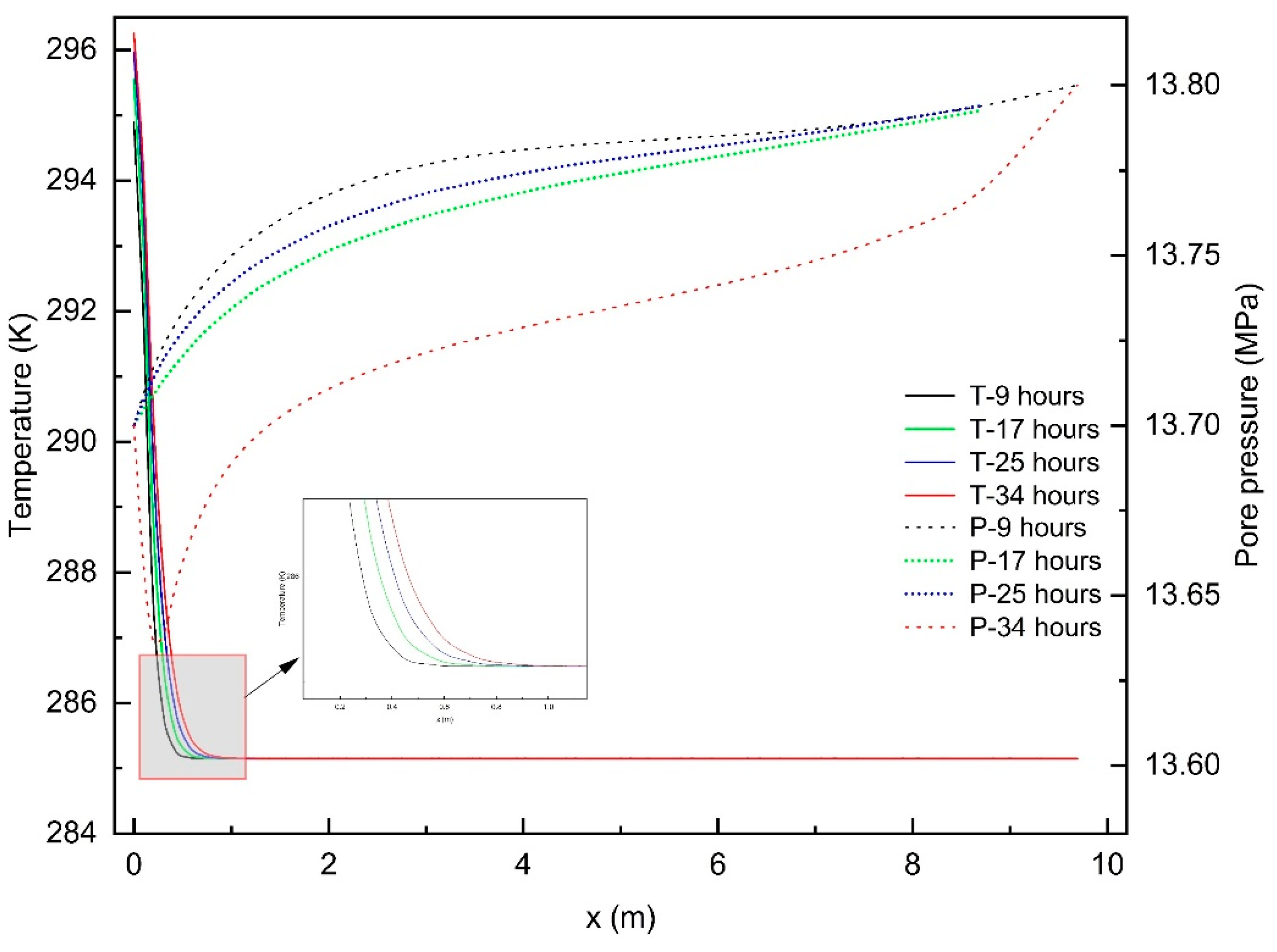
Figure 9.
Changes in hydrate saturation after wellbore opening.

Figure 10.
Distribution of hydrate saturation and Mises stress along the direction of maximum principal stress.
Figure 10.
Distribution of hydrate saturation and Mises stress along the direction of maximum principal stress.
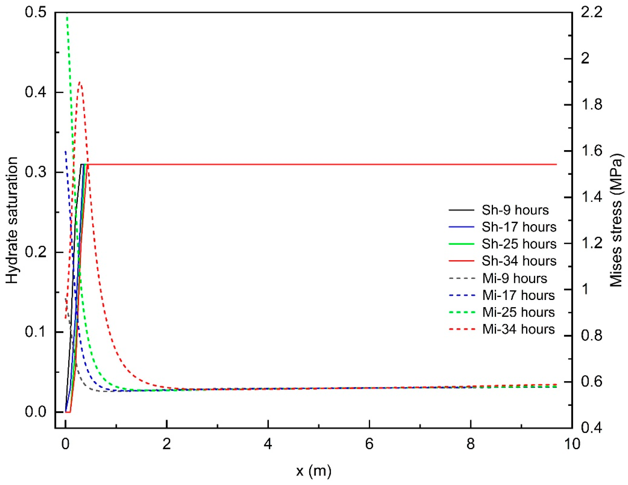
Figure 11.
After 36 h of wellbore opening: (a)—considering the elastic modulus, cohesive strength, and equivalent plastic strain distribution due to hydrate decomposition; (b)—not considering the elastic modulus, cohesive strength, and equivalent plastic strain distribution due to hydrate decomposition.

Figure 12.
(a)—Distribution of plastic strain and equivalent plastic strain during wellbore instability; (b)—distribution of Mises stress and pressure during wellbore instability.
Figure 12.
(a)—Distribution of plastic strain and equivalent plastic strain during wellbore instability; (b)—distribution of Mises stress and pressure during wellbore instability.
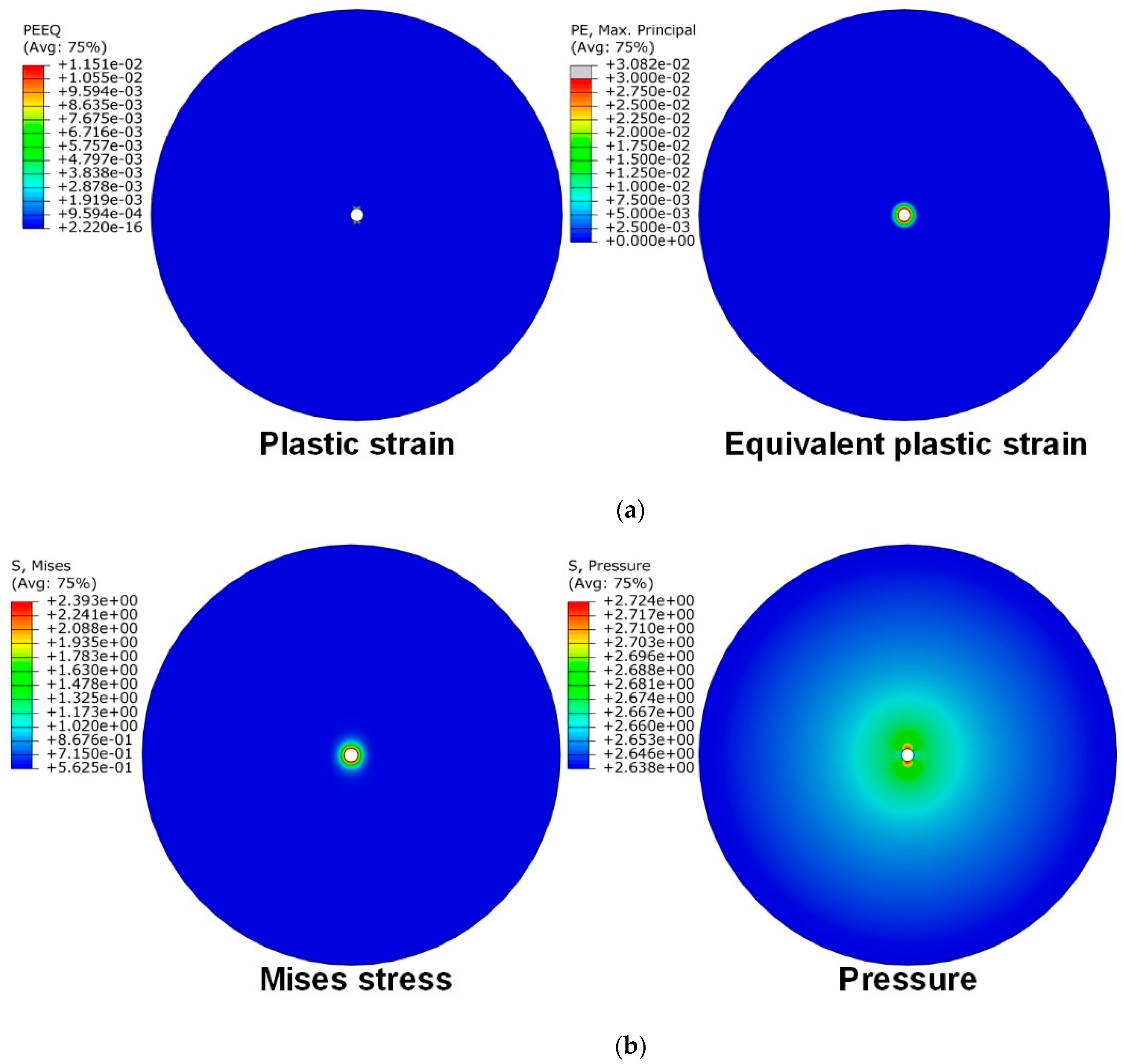
Figure 13.
The relationship curve between plastic strain, equivalent plastic strain, Mises stress, and time.
Figure 13.
The relationship curve between plastic strain, equivalent plastic strain, Mises stress, and time.

Figure 14.
Displacement curve in the direction of maximum principal stress over time.

Table 1.
Main parameters of the model.
| Parameters | Values |
|---|---|
| Initial hydrate saturation | 0.31 |
| Initial intrinsic permeability | 2.38 mD |
| Density of hydrate-bearing reservoirs | 1800 kg/m3 |
| Porosity of hydrate-bearing reservoirs | 0.31 |
| Initial cohesion of hydrate-bearing reservoirs | 1.1 MPa |
| Internal friction angle of hydrate-bearing reservoir | 35° |
| Initial modulus of elasticity of hydrate-bearing reservoirs | 565 MPa |
| Poisson's ratio for hydrate-bearing reservoirs | 0.25 |
| Pressure of the drilling fluid | 13.7 MPa |
| Pore pressure of the formation | 13.8 MPa |
| Density of seawater | 1030 kg/m3 |
| Specific heat capacity of water | 4200 J/kg/K |
| Specific heat capacity of rock | 800 J/kg/K |
| Thermal conductivity of hydrate | 0.39 W/m/K |
| Thermal conductivity of water | 0.56 W/m/K |
| Biot coefficient | 1 |
| Initial formation temperature | 12 °C |
| Temperature of the drilling fluid | 25.5 °C |
Disclaimer/Publisher’s Note: The statements, opinions and data contained in all publications are solely those of the individual author(s) and contributor(s) and not of MDPI and/or the editor(s). MDPI and/or the editor(s) disclaim responsibility for any injury to people or property resulting from any ideas, methods, instructions or products referred to in the content. |
© 2024 by the authors. Licensee MDPI, Basel, Switzerland. This article is an open access article distributed under the terms and conditions of the Creative Commons Attribution (CC BY) license (https://creativecommons.org/licenses/by/4.0/).
Share and Cite
MDPI and ACS Style
Sun, T.; Wen, Z.; Yang, J. Research on Wellbore Stability in Deepwater Hydrate-Bearing Formations during Drilling. Energies 2024, 17, 823. https://doi.org/10.3390/en17040823
AMA Style
Sun T, Wen Z, Yang J. Research on Wellbore Stability in Deepwater Hydrate-Bearing Formations during Drilling. Energies. 2024; 17(4):823. https://doi.org/10.3390/en17040823
Chicago/Turabian StyleSun, Ting, Zhiliang Wen, and Jin Yang. 2024. "Research on Wellbore Stability in Deepwater Hydrate-Bearing Formations during Drilling" Energies 17, no. 4: 823. https://doi.org/10.3390/en17040823
Note that from the first issue of 2016, this journal uses article numbers instead of page numbers. See further details here.