

Influence of Background Voltage Distortion on Operation of Passive Harmonic Compensation Devices


1
Department of Electric Power and Electromechanics, Saint Petersburg Mining University, 199106 St. Petersburg, Russia
2
Department of General Electrical Engineering, Saint Petersburg Mining University, 199106 St. Petersburg, Russia
*
Author to whom correspondence should be addressed.
Energies 2024, 17(6), 1342; https://doi.org/10.3390/en17061342
Submission received: 15 February 2024
/
Revised: 5 March 2024
/
Accepted: 7 March 2024
/
Published: 11 March 2024
(This article belongs to the Special Issue Power Quality and Disturbances in Modern Distribution Networks)
Abstract
:This paper discusses the issues of assessing the influence of external distortion sources on the functioning of a shunt passive harmonic filter. In this study, we evaluated the overload of a passive harmonic filter based on determining the contributions of distortion sources. A method was proposed for assessing the contributions of distortion sources, which allowed us, regardless of background distortions, to determine the contributions of consumer loads, as well as the contribution of background distortions. The simulation was carried out using the Simulink MatLab software (version R2023a). Several scenarios were considered in which the following values were varied: supply feeder impedance, level of background distortions, consumer electrical load composition, and passive filter parameters. It was found that the contribution of the background distortion source decreases with increasing impedance of the supply grid. It was determined that the consumer load contribution is independent of background voltage harmonics and can be used to estimate the overload of a passive harmonic filter. It was shown that it is necessary to take into account the overload of the passive filter by currents from background distortion sources, which did not exceed 135% of the rated rms current for the conditions under consideration. A mathematical model was proposed to estimate the overload of a passive filter in the presence of background voltage distortions. This model was obtained during analytical studies and allows one to evaluate the overload of a passive filter, taking into account the short circuit ratio, detuning frequency and power of the passive filter, and the share contribution of background distortion sources.
1. Introduction
Issues of improving power quality are addressed in many scientific articles by researchers from almost all countries of the world [1,2,3]. One of the main tasks within this area is to reduce the influence of harmonics on the operation of electrical equipment during the generation, transmission, distribution and consumption of electrical energy [4,5,6]. The relevance of this problem is emphasized by the significant increase in cases being considered in arbitration disputes between suppliers and consumers of electrical energy [7,8]. It should be noted that the main source of current harmonics is the electrical load of consumers, which has nonlinear current–voltage and weber–ampere characteristics. At the same time, the occurrence of harmonics in voltage is significantly influenced by the parameters of the power system, which in turn may include renewable energy sources [9,10,11]. In this case, the mutual influence of power system impedance and load parameters can lead to the occurrence of resonance phenomena, leading to a significant increase in the amplitude of harmonic currents and voltages. A number of works note that the utility is responsible for harmonic damping by changing the parameters of the distribution grid, and the consumer is responsible for the harmonic influence compensating for their own nonlinear load [12,13].
The imperfection of regulations and technical documentations, the difficulty of assessing harmonic distribution in electrical networks, the lack of approved methods for determining shared contributions, methods for determining discounts and surcharges depending on the power quality lead to situations in which, at the points of delivery, electrical energy as a product is of inadequate quality [14,15,16]. In some cases, power quality indicators may not correspond to standard values due to the presence of background voltage distortions at the point of common coupling [17,18].
Problems with assessing the share contribution of distortion sources and with designing harmonic level reduction devices arise in the presence of external sources of distortion relative to the consumer’s point of common coupling. There are known methods for estimating the contributions of distortion sources [19,20,21], but many of them are not applicable for determining the design parameters of harmonic-level reduction devices. For example, a method based on a Norton and Thevenin equivalent circuit with two consecutive measurements of harmonic currents and voltages at the PCC shows the grid and consumer contribution ratio of 55 to 45%, even when a shunt passive harmonic filter is used at a consumer bus with a nonlinear load. There are known technical means that make it possible to reduce the harmonic level in the grid, which in most scientific sources are usually classified into passive and active devices [22]. The design of parameters for such devices is complicated in the presence of background voltage distortions, information that may be unknown within one enterprise or consumer.
One of the main types of passive harmonic filters used in practice is the shunt (single-tuned) passive harmonic filter (SPHF). This type of passive filter is a circuit with low impedance at a certain frequency for consumer harmonic currents. There are many passive filter design techniques that do not take into account the effect of background distortions [22,23,24]. In the presence of an external distortion source, the harmonic current of this source will additionally flow through the passive filter circuit. The additional background current will be influenced by the energy system impedance, the load power and the parameters of the passive filter connected to the consumer. Articles [25,26] consider the problem of harmonic compensation using a passive harmonic filter for time-varying energy system parameters. The authors have developed a method for determining the optimal parameters of an LC filter, taking into account discrete capacitor parameters, time-varying grid impedance, voltage harmonics and load parameters. However, the share contribution of an external distortion source is not taken into account. The authors in [27] conduct a detailed study that evaluates the influence of grid and passive filter parameters on its performance. The influence of background distortions, which can lead to “strange behavior of the 5th harmonic amplitude in the current spectrum due to the additional 5th harmonic current flowing from the grid side,” is also considered. It is noted that the maximum or minimum value of harmonic currents and voltages is normally observed at the same resonant frequency. But in the presence of background distortions, this is not the case. In [28,29,30], the authors note that the energy system behaves as a harmonic current source and reduces the efficiency of the passive filter in terms of harmonic compensation. However, there is no assessment of such influence in mathematical form and no connection with the share contribution of external distortion sources. The work [31] proposes a new method for suppressing distortions by using the non-linearity current index to determine the parameters of the shunt single-tuned passive filter compensator in non-sinusoidal conditions. The emphasis is on maintaining the power factor within the desired limits while minimizing the nonlinear current of the customer’s loads in the power system at the point of common coupling. In this work, background voltage distortion components are taken into account. Also, a number of works take into account the influence of background voltage distortions [32,33], but it remains unclear how to determine the parameters of an external distortion source in practice.
Recently, active harmonic filters are often used in practice as a comprehensive solution to the problem of improving the power quality [34,35]. Most often, shunt active filters are used, the implementation of which does not take into account background voltage distortions. The presence of external distortion sources complicates the design of shunt active harmonic filter control systems and reduces the efficiency of their operation [36,37]. For example, when operating a shunt active harmonic filter, background voltage distortions remain uncompensated. However, the influence of background distortions on the operation of shunt active harmonic filters is beyond the scope of this work and will be considered in further research.
Thus, the purpose of this work is to assess the influence of external distortion sources on the design parameters of SPHF based on the calculation of consumer contributions, as well as to develop practical recommendations for taking into account the overload of SPHF by background harmonic currents.
2. Materials and Methods
2.1. Method for Determination the Share Contribution of Harmonic Sources
Here, it is necessary to clarify the concept of external and internal distortion sources. Let us consider a single consumer (consumer 1) connected to the energy system with impedance ZS at the point of common coupling (PCC) in Figure 1. Several consumers can be connected at this point. Typically, an industrial consumer is connected through its own supply transformer (T) to the PCC. Load 1 and load 2 of consumer 1 can include nonlinear and linear loads. Current harmonics injected by consumer 1 affect the voltage quality at the PCC (at the high voltage side of the transformer) and at the consumer buses. This nonlinear load refers to the internal distortion source (connected at the low voltage side of the transformer). Other consumers with nonlinear loads connected to the PCC are considered as external distortion sources. These consumers are sources of background voltage harmonics at the PCC and at the consumer buses. Also, harmonic currents flow through the transformer of consumer 1 from the nonlinear load of other consumers. These currents will be called background harmonic currents.
Determining the contributions of distortion sources is an important task when designing the parameters of harmonic mitigation devices. This applies primarily to external distortion sources, the influence of which is difficult to take into account when implementing both active and passive harmonic filters. In this case, it is important to evaluate the harmonic voltage on the consumer bus, which will remain the same if the current harmonics injected by internal distortion sources are reduced to zero. This can be explained by considering the case in which the voltage harmonics at the consumer bus consist of harmonics from external and internal distortion sources. Reducing to zero the current harmonics injected by internal sources of distortion (for example, using a shunt active filter) will not lead to a reduction in voltage harmonics on the consumer bus to zero. In this case, the voltage harmonics will be determined by the background voltage harmonics. This indicates reduced effectiveness of harmonic mitigation devices.
The authors developed a method for assessing the contributions of distortion sources in order to adjust existing methods for designing passive filter parameters by taking into account the influence of background distortions. The method for determining the contributions of distortion sources can be demonstrated on a simplified equivalent circuit diagram of an electrical grid, the parameters of which are presented at harmonic frequencies (Figure 2). In this case U3h is the background voltage harmonic distortion, UPCCh is the voltage harmonic distortion at the PCC, UCh is the voltage harmonic distortion at the consumer bus, I01h is the nonlinear load harmonic current of Load 1, I02h is the nonlinear load harmonic current of Load 2, ICh is the supply feeder harmonic current of the consumer, I1h is the total harmonic current of Load 1, I2h is the total harmonic current of Load 2, IZ1h is the linear load harmonic current of Load 1, IZ2h is the linear load harmonic current of Load 2, IFh is the harmonic current of the passive filter, ZSh is the energy system equivalent of harmonic impedance, Z1h is the equivalent harmonic impedance of Load 1, Z2h is the equivalent harmonic impedance of Load 2, ZFh is the equivalent harmonic impedance of the shunt passive filter, ZTh is the harmonic impedance of the supply transformer and S is the switch.
Case 1—S1 is ON, S2 is OFF. This case corresponds to the absence of a passive filter and background distortions. According to the superposition principle, it follows the equation below.
where ZΣh is the equivalent harmonic impedance of the scheme; U01h is the harmonic voltage, which is obtained when current I01h flows through ZΣh; U02h Is the harmonic voltage, which is obtained when current I02h flows through ZΣh. Based on Equation (1), the following equations can be obtained:
The Equations (2) and (3) mean that the voltage contributions from nonlinear loads of Load 1 and Load 2 to the total voltage distortion at the consumer bus are determined through the harmonic currents of the nonlinear load. In algebraic form, taking into account the projections of harmonic current vectors I01h and I02h onto the total harmonic current vector (I01h + I02h), the Equations (2) and (3) can be written as follows:
where K1Dh, K2Dh are the contributions of distortion sources to the total voltage distortion at the consumer bus; ψ01h, ψ02h are the phase angles of nonlinear load harmonic currents I01h and I02h, respectively; ψ012h is the phase angle of the total harmonic current of nonlinear loads (I01h + I02h).
However, determining the harmonic currents I01h and I02h, as well as their summation, seems difficult, especially in the presence of external distortion sources. This paper proposes the application of a shunt passive harmonic filter to solve this problem. Consider the following case.
Case 2—S1 is ON, S2 is ON. This case corresponds to the absence of background distortions and the presence of a passive filter. The principle is easy to demonstrate in the ideal case in which the passive filter equivalent impedance at the hth harmonic frequency is zero. In this case, harmonic currents IZ1h and IZ2h become zero. The harmonic currents of the nonlinear load I01h and I02h flow entirely through the filter circuit, as follows:
Thus, by measuring the harmonic currents of Load 1, Load 2 (I1h and I2h) and the passive filter IFh, it is possible to determine the contributions of distortion sources to the total voltage distortion at the consumer bus. It should be noted that if there is an external source of distortion and an ideal passive filter (with zero impedance at the hth harmonic frequency) is connected, the harmonic current arising from the source U3h flows entirely through the passive filter circuit at the hth harmonic frequency and there is no problem in determining the contribution of the external distortion source.
However, in real conditions, it is necessary to take into account the filter resistance, as well as its frequency detuning due to the discrete parameters of inductors and capacitors. In this case, the measurement of the harmonic currents I1h and I2h corresponds to a certain error of the currents I01h and I02h. An estimation of such an error is given in [38,39] and is insignificant due to the fact that the harmonic impedance of the filter at the hth harmonic frequency is significantly less than the harmonic impedance of Load 1 and Load 2 of the consumer at the same frequency. Then harmonic currents I1h and I2h flow through the supply feeder circuit and the passive filter circuit at the hth harmonic frequency. So, the equivalent harmonic current, equal to the sum of harmonic currents I1h and I2h, can be determined by measuring the harmonic currents in the supply feeder circuit ICh and the passive filter circuit IFh. Thus, the contributions of consumer loads can be determined by measuring the currents ICh, IFh, I1h and I2h. The Equations (4) and (5) can be written as follows:
where ψ1h, ψ2h are the phase angles of harmonic currents I1h and I2h, respectively; ψ12h is the phase angle of the harmonic current obtained by summing the supply feeder harmonic current ICh and the passive filter harmonic current IFh.
It should be noted that the presence of external distortion sources in this case does not affect the determination of the share contributions of internal distortion sources. The harmonic current flowing from the external voltage source U3h (background harmonic current) will reduce the harmonic current ICh to I’Ch according to the superposition principle. Further, flowing through the passive filter circuit at the hth harmonic frequency, the background harmonic current will increase the harmonic current IFh to I’Fh. But the sum of these harmonic currents will remain practically unchanged (ICh + IFh ≈ I’Ch + I’Fh). This property of the proposed method allows one consumer, regardless of external conditions (presence of background distortions), to determine the most significant load connections in order to further compensate for distortions.
Case 3—S1 is OFF, S2 is OFF. This case corresponds to the presence of background distortions and the absence of a passive filter. This case is important to consider from the point of view of designing harmonic compensation devices.
The presence of background distortions leads to additional loading of the SPHF with a harmonic current from an external source (background harmonic current). In this case, the background harmonic current depends on many factors: the initial phase of nonlinear load harmonic currents, types of rectifiers, short circuit power at the connection point, SPHF parameters, linear load power, etc. When considering filter overload, it is important to estimate the maximum possible value, which will be determined by the magnitude of background harmonic voltage U3h. Based on Figure 2, in accordance with the indicated current directions, the harmonic voltage U3h and the contribution of the external distortion source K3Dh can be determined by Equations (9) and (10):
The contribution of the external distortion source K3Dh will determine the maximum current addition to the passive harmonic filter overload. When using shunt active harmonic filters, which eliminate the influence of internal distortion sources, the contribution identified by Equation (10) is also important. It shows the maximum possible value of the harmonic voltage that will remain on the consumer buses if the influence of internal distortion sources is completely eliminated.
2.2. Description of Simulation Model and Parameters
A simplified single-line diagram of a consumer installation is presented in Figure 3. The consumer equipment includes various types of electrical energy converters (uncontrolled full-wave bridge rectifier UR and thyristor power regulator TPR), a linear load in the form of an asynchronous motor M and a capacitor bank CB with an antiharmonic reactor, as well as a SPHF for assessing the contributions of distortion sources and overloading the filter with background harmonic currents. Thyristor controlled full-wave bridge rectifier TR represents other consumers connected to the PCC. The loads of the converters UR, TPR and TR include resistances RUR, RTPR and RTR, respectively. The inductor Ls1 with internal resistance Rs1 represents the energy system impedance. The inductor Ls2 with internal resistance Rs2 represents the impedance of the supply transformer through which the consumer is connected to the PCC.
The load and grid parameters are presented in Table 1. The equipment and parameters of the simulation model were selected based on their compliance with the parameters of the laboratory equipment. In further research, it is planned to confirm the simulation results on a laboratory test bench.
The simulation was carried out in the MATLAB Simulink software (version R2023a). Simulation can be divided into several stages.
Stage 1. Contribution assessment of internal distortion sources.
The contributions of internal distortion sources were assessed using the proposed method in Section 2.1. At the same time, the parameters of the external distortion source TR were varied by changing RTR and the parameters of the supply feeder ZS2 were varied by changing the step of regulation (step 1–step 4).
Stage 2. Contribution assessment of external distortion sources.
The contributions of external distortion sources were assessed using the proposed method in Section 2.1. At the same time, the parameters of the external distortion source TR were varied by changing RTR and the parameters of the supply feeder ZS2 were varied by the changing step of regulation (step 1–step 4).
Stage 3. SPHF overload assessment by background harmonic currents.
The additional loading of the SPHF by background harmonic currents was assessed using the proposed method in Section 2.1. At the same time, the parameters of the external distortion source TR were varied by changing RTR and the parameters of the supply feeder ZS2 were varied by changing the step of regulation (step 1–step 4). For different load compositions (mode 1—all consumer loads are connected, mode 2—all consumer loads are connected except UR, mode 3—all consumer loads are connected except TPR), the following values of the SPHF harmonic currents were measured:
- -
- The SPHF harmonic current when external distortion source TR is disconnected and all consumer loads are connected for the corresponding mode (IFh_0);
- -
- The SPHF harmonic current when external distortion source TR is connected and all consumer loads are connected for the corresponding mode (IFh_1);
- -
- The SPHF harmonic current when external distortion source TR is connected and all consumer loads (except SPHF) are disconnected (IFh_2).
The value ΔIF1h = IFh_1/IFh_0 shows the real addition to the SPHF harmonic current from an external distortion source, since the total SPHF harmonic current is a geometric summation of the components from all distortion sources. The value ΔIF2h = IFh_2/IFh_0 shows the maximum addition to the SPHF harmonic current from an external distortion source, since there are no components from internal distortion sources.
The values of variable parameters and the composition of electrical equipment during simulation are presented in Table 2. Here, the sign «+» indicates that the equipment is connected and the sign «−» indicates that the equipment is disconnected.
At stage 1 and 2, all types of linear and nonlinear loads are connected. At stage 3, the composition of the load will change due to the disconnection of the consumer nonlinear loads.
3. Results and Discussion
This section is divided into subsections, which present the simulation results in accordance with Section 2.2. The results of analytical studies are also presented, which allows practical calculations of SPHF additional loading by background harmonic currents.
3.1. Simulation Results
3.1.1. Contribution of Internal Distortion Sources Depending on the Parameters of the External Source and the Supply Feeder
Figure 4 shows the dependence of the contributions of internal distortion sources (UR, TPR), as well as the contributions of the linear load (M, CB) depending on the parameters of the supply feeder. Variables with index 1 (UR1, TPR1, M1, CB1) correspond to the disconnected external nonlinear load TR. Variables with index 2 (UR2, TPR2, M2, CB2) correspond to the connected external nonlinear load TR. The impedance ZS2 was varied by changing the regulation step (Step 1 to Step 4) according to the values in Table 1.
It follows from the graph in Figure 4 that contribution of UR varies from 60 to 70%, the contribution of TPR varies from 30 to 45%, the contribution of M varies around 0%, and the contribution of CB varies from 0 to −5%. The contribution of CB is negative and indicates a compensating effect on the total distortions. In this case, the capacitor banks can be turned off for the duration of the measurements in order to increase the accuracy of the contribution assessment. The share contributions of internal distortion sources remain practically unchanged in the presence and absence of external distortion sources. This makes it possible to assess the share contributions of internal distortion sources regardless of background distortions. At the same time, the contributions of UR and TPR change with different parameters of the supply feeder, which is explained by changes in their internal impedance at harmonic frequencies. The error values for estimating the load contributions of the consumer in the presence and absence of external distortions are presented in Table 3. The error values δKDh for UR and TPR were calculated using the following expression:
where KDh1 is the share contribution of the consumer load when TR is disconnected and KDh2 is the share contribution of the consumer load when TR is connected.
The error in estimating the consumer load contributions in the presence and absence of external distortions increases with increasing values of background voltage distortion and the impedance of the supply feeder, but does not exceed 10% for the conditions under consideration (see Step 1 in Table 3 for RTR = 20 Ω).
3.1.2. Contribution of External Distortion Sources Depending on the Parameters of the Supply Feeder
Figure 5 shows the dependence of the contribution of the external distortion source K3Dh depending on the resistance RTR and the impedance of the supply feeder. All electrical loads are connected to the PCC. The share contribution was determined by Equation (10).
It follows from the graph in Figure 5 that the contribution of background distortions decreases as the power of the external distortion source decreases and as the impedance of the supply feeder increases. In practice, it is possible to reduce the impedance of the supply feeder by varying the parameters of the supply transformer, which is determined as follows:
where ZT is the transformer impedance taking into account the transformation ratio, ZTrated is the transformer impedance for the rated voltage, N is the number of transformer taps and β is the voltage change when moving the tap switch to the next position, p.u.
3.1.3. Assessment of SPHF Overload by Currents from an External Distortion Source
As part of the simulation, the SPHF harmonic current was assessed in the presence of an external distortion source. Figure 6 shows the dependences of the relative value of SPHF harmonic currents ΔIFh on the resistance of the external distortion source TR for different electrical load compositions specified in Section 2.2. The dependences in Figure 6 correspond to the supply feeder impedance in Step 1.
It follows from the graph in Figure 6 that an increase in the power of the external distortion source leads to an increase in the SPHF harmonic current. However, there are values that are below unity, which is due to the different types of converters in the scheme (this corresponds to cases with the index “real”). The relative addition to the SPHF harmonic current from an external distortion source depends on the composition and type of nonlinear electrical loads. This means that the current harmonic components from different types of semiconductor converters can cancel each other in the passive filter branch. However, in the presence of distortion sources with the same types of rectifiers, the SPHF harmonic current can be determined by the algebraic sum of the harmonic components from all sources. Then, the background harmonic current will be algebraically added to the harmonic current from internal sources (this corresponds to cases with the index “max”).
Additional studies were carried out using the previously discussed simulation model, in which all converters were represented by the same type (uncontrolled rectifiers). The values of SPHF harmonic currents IF1h_0, IF1h_1 and IF1h_2 were assessed for Step 1 and Step 4 supply feeder impedance. The error values δ1 for Step 1 supply feeder impedance and δ4 for Step 4 supply feeder impedance were calculated by using the following expression:
The results are presented in Table 4.
From the data in Table 4, it is clear that with the same types of converters, the maximum and real addition differ from each other by 3% for the Step 1 supply feeder impedance and by 8% for the Step 4 supply feeder impedance. Evidently, with an increase in the supply feeder impedance, the addition to the SPHF harmonic current from an external distortion source is reduced.
When analyzing semiconductor converters of external distortion sources, there is often no information about their parameters and types. Therefore, it seems appropriate to estimate the maximum addition to the SPHF harmonic current from external distortion sources.
From the SPHF overload point of view at the fundamental frequency, the contribution of the background harmonic current to the RMS value of the passive filter current is of interest. Figure 7 shows the dependence of the RMS current ratio, taking into account the maximum addition Imax and the real addition Ireal to the RMS current for different load composition and supply feeder impedance values.
It follows from the graph in Figure 7 that the RMS current value, taking into account the maximum addition, exceeds the RMS value of the passive filter current, taking into account the real addition, by 34% (for mode 1, where three different types of nonlinear loads are connected). This corresponds to the following grid and load parameters: STR = 11 kVA, SUR = 2.8 kVA, STPR = 2.7 kVA and Ssc1/Ssc2 = 2 (for Step 1 supply feeder impedance). For mode 1 parameters, close to low-voltage electrical grids (Ssc1/Ssc2 = 10, for Step 4 supply feeder impedance), the RMS current ratio is about 1.1.
3.2. Analytical Calculation of SPHF Overload by Background Harmonic Currents
The background harmonic current flowing through the SPHF can be calculated analytically. From the above dependencies, it is clear that the background harmonic current of the filter is determined mainly by the following parameters:
- -
- Power of the external distortion source;
- -
- Short circuit power at the consumer buses;
- -
- Short circuit power at the point of external nonlinear load connection;
- -
- Parameters of the passive harmonic filter.
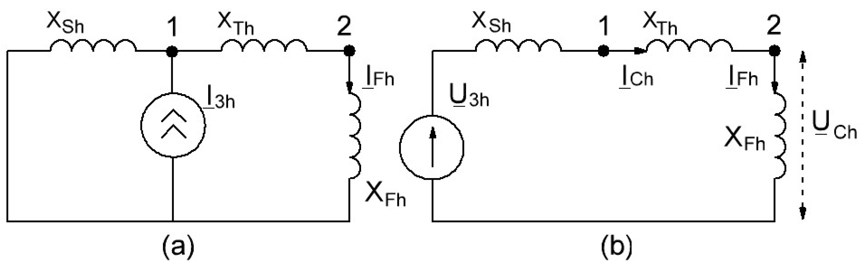
The relationship between these parameters can be shown using the simplified equivalent circuit shown in Figure 8, which takes into account the presence of external distortion sources, where U3h is the voltage source of background harmonic distortion, I3h is the current source of background harmonic distortion, UCh is the voltage harmonic distortion at the consumer bus, ICh is the supply feeder harmonic current of the consumer, XSh is the energy system harmonic inductive reactance, XFh is the equivalent harmonic inductive reactance of the shunt passive filter and XTh is the harmonic inductive reactance of the supply transformer. The circuits in Figure 8 are presented for the hth harmonic frequency, which is close to (slightly below) the resonant frequency of the passive harmonic filter (the equivalent impedance of the passive filter is inductive).
The schemes (a) and (b) in Figure 8 are equivalent to each other and are used with either a current source or a voltage source of harmonic distortion. Figure 8b was designed based on Figure 2, but with the following assumptions:
- -
- The parameters of the linear load connected in parallel to the passive filter are not taken into account at the hth harmonic because the equivalent impedance of the passive filter at the hth harmonic (near the resonant frequency) is very low;
- -
- The parameters of the power system and the supply transformer are assumed to be inductive;
- -
- The resistance of the SPHF is not taken into account.
Consider the scheme in Figure 8a. This scheme can be considered in the case when the parameters of the external nonlinear load (harmonic currents) are known. From Figure 8a, it is obvious that the current magnitude of the passive harmonic filter can be calculated as follows:
The transformer and power system parameters can be represented through the short circuit power Ssc1 at point 1 and Ssc2 at point 2. The filter parameters can be represented through the detuned factor fr and the reactive power of the filter capacitor bank QCB at the fundamental frequency. For example, if the resonance frequency of the passive filter is 237.5 Hz and the harmonic frequency is 250 Hz (5% filter detuning), then fr is equal to 0.95. As a result, the following expressions were obtained:
If an uncontrolled rectifier is considered with a DC link in the form of inductance as an external nonlinear load, then the harmonic current can be calculated as Ih = I1/h. Then, Equation (15) is transformed into Equation (18) as follows:
where SUR is the power of the uncontrolled rectifier, h is the order of the harmonic and Urated is the nominal voltage of the uncontrolled rectifier.
Consider the scheme in Figure 8b. This scheme can be considered in the case when the parameters of the external nonlinear load are unknown and measurements are required at the consumer side. In this case, it is necessary to calculate the background harmonic voltage through the measured parameters ICh and UCh:
Then, the background harmonic current can be written in the following form:
Verification of the proposed Equation (15) was carried out by comparing the calculated values with the simulation results for mode 1 with TR resistance RTR = 20 Ω. The value KSC was calculated according to Equation (17). The values I3h_meas and IFh_meas were obtained based on simulation results by measuring harmonic currents at the TR connection to the PCC and at the passive filter feeder, respectively. The value IFh_calc was calculated according to Equation (15). The error value δI was calculated by using the followingequation:
The comparison results are presented in Table 5.
From the data in Table 5, it follows that the error in estimating the calculated SPHF background harmonic currents relative to the harmonic currents of the simulation model do not exceed 5% in amplitude (see |δI| = 4.49% in Table 5). Thus, based on the identified equations that allow one to calculate the SPHF background harmonic current, it is possible to evaluate the influence of external distortion sources depending on the short circuit ratio, reactive power and detuned factor of the passive filter, the harmonic order and value of the external source harmonic current.
The identified equations can be used in existing methods for designing parameters of passive shunt harmonic filters in order to take into account the influence of an external distortion sources on the overload of a passive harmonic filter.
4. Conclusions
This paper assessed the influence of external distortion sources on the operation of a shunt passive harmonic filter. We evaluated the SPHF overload based on determining the contributions of distortion sources. The dependences of the contributions of internal and external distortion sources on the supply feeder impedance, parameters of the SPHF and nonlinear electrical load were identified based on simulation studies in the platform Simulink MatLab. It was shown that the share contribution of external distortion sources decreases when increasing the supply feeder impedance. The SPHF overload ratio from the external distortion source did not exceed 35% for the conditions under consideration with a short circuit factor of 2. Based on analytical studies, a mathematical model was developed for assessing the SPHF background harmonic current, taking into account the short circuit ratio, reactive power and detuned factor of the passive filter, as well as the share contribution of external distortion sources. The error in estimating the SPHF background harmonic current using the proposed equation does not exceed 5% relative to the values based on the simulation results.
Author Contributions
Conceptualization, A.S.; methodology, A.S. and Y.S.; simulation, A.S. and I.G.; writing—original draft preparation, A.S.; supervision and project administration, A.S. and Y.S.; writing—review and editing, A.S. and Y.S. All authors have read and agreed to the published version of the manuscript.
Funding
This research was financially supported by the Russian Science Foundation under grant No. 21-79-10027, https://rscf.ru/en/project/21-79-10027/ (accessed on 6 March 2024).
Data Availability Statement
Data are contained within the article.
Conflicts of Interest
The authors declare no conflicts of interest.
References
- Bagheri, A.; de Oliveira, R.A.; Bollen, M.H.J.; Gu, I.Y.H. A Framework Based on Machine Learning for Analytics of Voltage Quality Disturbances. Energies 2022, 15, 1283. [Google Scholar] [CrossRef]
- Kanálik, M.; Margitová, A.; Beňa, Ľ.; Kanáliková, A. Power System Impedance Estimation Using a Fast Voltage and Current Changes Measurements. Energies 2020, 14, 63. [Google Scholar] [CrossRef]
- Bogdanov, I.; Abramovich, B. Improving the efficiency of autonomous electrical complexes of oil and gas enterprises. J. Min. Inst. 2021, 249, 408–416. [Google Scholar] [CrossRef]
- Morenov, V.; Leusheva, E.; Lavrik, A.; Lavrik, A.; Buslaev, G. Gas-Fueled Binary Energy System with Low-Boiling Working Fluid for Enhanced Power Generation. Energies 2022, 15, 2551. [Google Scholar] [CrossRef]
- Khalifa, A.; Bazhin, V.; Ustinova, Y.; Shalabi, M. Study of the Kinetics of the Process of Producing Pellets from Red Mud in a Hydrogen Flow. J. Min. Inst. 2022, 254, 261–270. [Google Scholar] [CrossRef]
- Ustinov, D.A.; Aysar, A.R. Development of a New Working Algorithm for Improving the Efficiency of the Remote Protection in the Distributed Generation Networks. Occup. Saf. Ind. 2023, 5, 20–27. [Google Scholar] [CrossRef]
- Bhattacharyya, S.; Cobben, S.; Ribeiro, P.; Kling, W. Harmonic Emission Limits and Responsibilities at a Point of Connection. IET Gener. Transm. Distrib. 2012, 6, 256–264. [Google Scholar] [CrossRef]
- Crepaldi, J.; Amoroso, M.M.; Ando, O.H. Analysis of the Topologies of Power Filters Applied in Distributed Generation Units—Review. IEEE Lat. Am. Trans. 2018, 16, 1892–1897. [Google Scholar] [CrossRef]
- Belsky, A.; Glukhanich, D.; Sutikno, T.; Hatta Jopri, M. Estimation of Hourly Solar Irradiation on Tilted Surfaces. Bull. Electr. Eng. Inform. 2023, 12, 3202–3214. [Google Scholar] [CrossRef]
- Ustinov, D.A.; Aysar, A.R. Analysis of the Impact of the Distributed Generation Facilities on Protection Systems and Voltage Mode: Review. Occup. Saf. Ind. 2023, 2, 15–20. [Google Scholar] [CrossRef]
- Buslaev, G.; Lavrik, A.; Lavrik, A.; Tcvetkov, P. Hybrid System of Hydrogen Generation by Water Electrolysis and Methane Partial Oxidation. Int. J. Hydrogen Energy 2023, 48, 24166–24179. [Google Scholar] [CrossRef]
- Fujita, H.; Yamasaki, T.; Akagi, H. A Hybrid Active Filter for Damping of Harmonic Resonance in Industrial Power Systems. IEEE Trans. Power Electron. 2000, 15, 215–222. [Google Scholar] [CrossRef]
- Bai, H.; Wang, X.; Loh, P.C.; Blaabjerg, F. Harmonic Analysis and Mitigation of Low-Frequency Switching Voltage Source Inverter with Series LC Filtered VSI. In Proceedings of the 2017 IEEE Applied Power Electronics Conference and Exposition (APEC), Tampa, FL, USA, 26–30 March 2017; pp. 3299–3306. [Google Scholar] [CrossRef]
- Srivastava, M.; Goyal, S.K.; Saraswat, A.; Shekhawat, R.S.; Gangil, G. A Review on Power Quality Problems, Causes and Mitigation Techniques. In Proceedings of the 2022 1st International Conference on Sustainable Technology for Power and Energy Systems (STPES), Srinagar, India, 4–6 July 2022; pp. 1–6. [Google Scholar] [CrossRef]
- Kazmierkowski, M.P. Power Quality: Problems and Mitigation Techniques [Book News]. IEEE Ind. Electron. Mag. 2015, 9, 62. [Google Scholar] [CrossRef]
- Zhukovskiy, Y.; Korolev, N.; Malkova, Y. Monitoring of Grinding Condition in Drum Mills Based on Resulting Shaft Torque. J. Min. Inst. 2022, 256, 686–700. [Google Scholar] [CrossRef]
- Karadeniz, A.; Balci, M.E. Comparative Evaluation of Common Passive Filter Types Regarding Maximization of Transformer’s Loading Capability under Non-Sinusoidal Conditions. Electr. Power Syst. Res. 2018, 158, 324–334. [Google Scholar] [CrossRef]
- Gimenes, T.K.; da Silva, M.P.C.; Ledesma, J.J.G.; Ando, O.H. Impact of Distributed Energy Resources on Power Quality: Brazilian Scenario Analysis. Electr. Power Syst. Res. 2022, 211, 108249. [Google Scholar] [CrossRef]
- Jopri, M.H.; Ghani, M.A.; Abdullah, A.; Sutikno, T.; Manap, M.; Too, J. Naïve Bayes and Linear Discriminate Analysis Based Diagnostic Analytic of Harmonic Source Identification. Indones. J. Electr. Eng. Comput. Sci. 2020, 20, 1626–1633. [Google Scholar] [CrossRef]
- Martinez, R.; Castro, P.; Arroyo, A.; Manana, M.; Galan, N.; Moreno, F.S.; Bustamante, S.; Laso, A. Techniques to Locate the Origin of Power Quality Disturbances in a Power System: A Review. Sustainability 2022, 14, 7428. [Google Scholar] [CrossRef]
- Shcherbakova, P.; Senderovych, G.; Abramovitz, A. Revisiting the Active Power Direction Method. IET Gener. Transm. Distrib. 2021, 15, 1056–1069. [Google Scholar] [CrossRef]
- Mohamed, I.F.; Abdel Aleem, S.H.E.; Ibrahim, A.M.; Zobaa, A.F. Optimal Sizing of C -Type Passive Filters under Non-Sinusoidal Conditions. Energy Technol. Policy 2014, 1, 35–44. [Google Scholar] [CrossRef]
- Abdel Aleem, S.H.E.; Elmathana, M.T.; Zobaa, A.F. Different Design Approaches of Shunt Passive Harmonic Filters Based on IEEE Std. 519-1992 and IEEE Std. 18-2002. Recent Patents Electr. Electron. Eng. 2013, 6, 68–75. [Google Scholar] [CrossRef]
- Ko, W.; Tuomainen, M. Design and Application of a Single-tuned Passive Harmonic Filter to Suppress Harmonic Distortion and Resonance for Railway Traction Power Systems—A Case Study. IET Electr. Syst. Transp. 2022, 12, 153–164. [Google Scholar] [CrossRef]
- AbdelAziz, M.M.; AbouEl-Zahab, E.E.-D.; Ibrahim, A.M.; Zobaa, A.F. Practical Considerations Regarding Power Factor for Nonlinear Loads. IEEE Trans. Power Deliv. 2004, 19, 337–341. [Google Scholar] [CrossRef]
- Aziz, M.M.A.; Zobaa, A.F.; Ibrahim, A.M.; Monem, A.M.A. Effect of Time Variation of System Impedance and Voltage Harmonics on LC Compensation for Nonlinear Loads. In Proceedings of the 2004 11th International Conference on Harmonics and Quality of Power (IEEE Cat. No.04EX951), Lake Placid, NY, USA, 12–15 September 2004; pp. 77–82. [Google Scholar] [CrossRef]
- Azebaze Mboving, C.S.; Hanzelka, Z.; Firlit, A. Analysis of the Factors Having an Influence on the LC Passive Harmonic Filter Work Efficiency. Energies 2022, 15, 1894. [Google Scholar] [CrossRef]
- Aleem, S.H.E.A.; Balci, M.E.; Zobaa, A.F.; Sakar, S. Optimal Passive Filter Design for Effective Utilization of Cables and Transformers under Non-Sinusoidal Conditions. In Proceedings of the 2014 16th International Conference on Harmonics and Quality of Power (ICHQP), Bucharest, Romania, 25–28 May 2014; pp. 626–630. [Google Scholar] [CrossRef]
- Abdul Kahar, N.H.B.; Zobaa, A.F. Application of Mixed Integer Distributed Ant Colony Optimization to the Design of Undamped Single-Tuned Passive Filters Based Harmonics Mitigation. Swarm Evol. Comput. 2019, 44, 187–199. [Google Scholar] [CrossRef]
- Nassif, A.; Xu, W.; Freitas, W. An Investigation on the Selection of Filter Topologies for Passive Filter Applications. In Proceedings of the IEEE PES General Meeting, Minneapolis, MN, USA, 25–29 July 2010; p. 1. [Google Scholar] [CrossRef]
- Almutairi, M.S.; Hadjiloucas, S. Harmonics Mitigation Based on the Minimization of Non-Linearity Current in a Power System. Designs 2019, 3, 29. [Google Scholar] [CrossRef]
- Filho da Costa Castro, J.; Lima, L.R.; Belchior, F.N.; Ribeiro, P.F. A Novel Approach to the Design of Passive Filters in Electric Grids. Int. J. Emerg. Electr. Power Syst. 2016, 17, 693–701. [Google Scholar] [CrossRef]
- Menti, A.; Zacharias, T.; Milias-Argitis, J. Optimal Sizing and Limitations of Passive Filters in the Presence of Background Harmonic Distortion. Electr. Eng. 2009, 91, 89–100. [Google Scholar] [CrossRef]
- Benaouadj, M.; Boumous, Z.; Boumous, S. Active Harmonic Filtering for Improving Power Quality of an Electrical Network. J. Eur. Syst. Autom. 2022, 55, 397–403. [Google Scholar] [CrossRef]
- Hoon, Y.; Mohd Radzi, M.; Hassan, M.; Mailah, N. Control Algorithms of Shunt Active Power Filter for Harmonics Mitigation: A Review. Energies 2017, 10, 2038. [Google Scholar] [CrossRef]
- Davi Curi Busarello, T.; Vendrusculo, E.A.; Pomilio, J.A.; da Silva, N. Analysis of a Derivative Hybrid Power Filter in Distorted Voltage Grid. In Proceedings of the 2013 IEEE PES Conference on Innovative Smart Grid Technologies (ISGT Latin America), Sao Paulo, Brazil, 15–17 April 2013; pp. 1–5. [Google Scholar] [CrossRef]
- Mahmoud, M.O.; Mamdouh, W.; Khalil, H. Source Current Harmonic Mitigation of Distorted Voltage Source by Using Shunt Active Power Filter. Int. J. Electr. Comput. Eng. 2020, 10, 3967–3977. [Google Scholar] [CrossRef]
- Skamyin, A.; Belsky, A.; Dobush, V.; Gurevich, I. Computation of Nonlinear Load Harmonic Currents in the Presence of External Distortions. Computation 2022, 10, 41. [Google Scholar] [CrossRef]
- Zhukovskiy, Y.L.; Vasilev, B.Y.; Korolev, N.A.; Malkova, Y.M. Analysis of the behavior of asynchronous electric drive with a closed scalar control system when changing the inductance of the magnetizing circuit. Indones. J. Sci. Technol. 2022, 8, 65–78. [Google Scholar] [CrossRef]
Figure 1.
The electrical scheme with connected consumers at the PCC.

Figure 2.
The equivalent electrical scheme with background harmonic distortions.
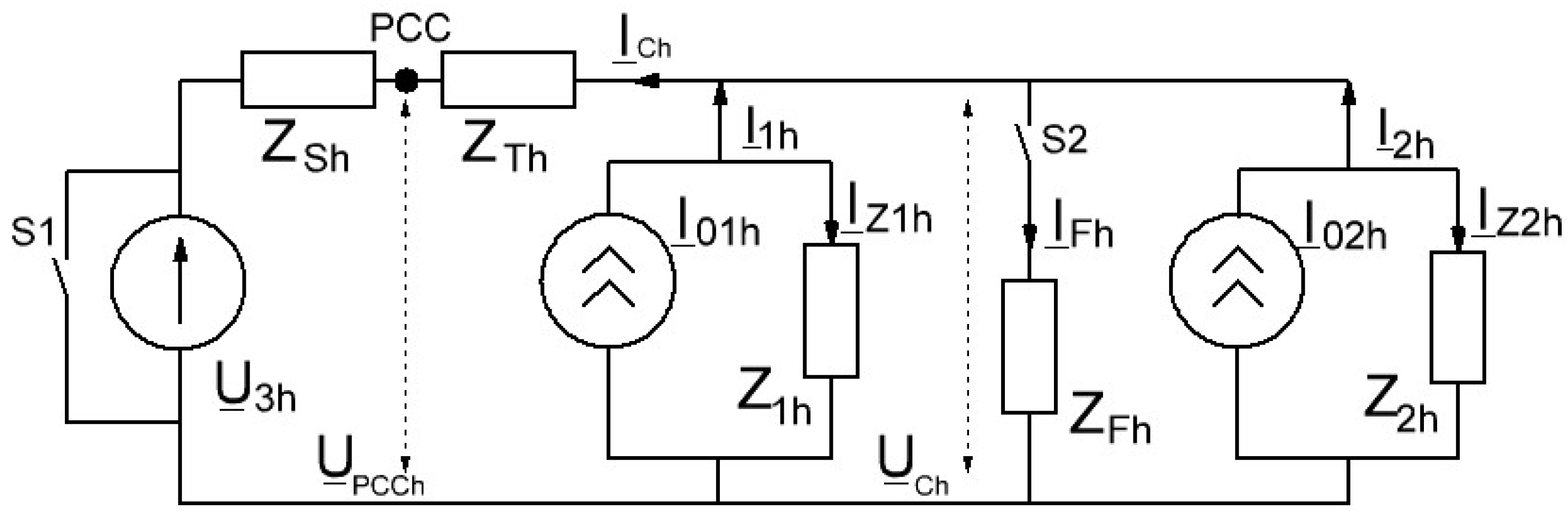
Figure 3.
The scheme under study.
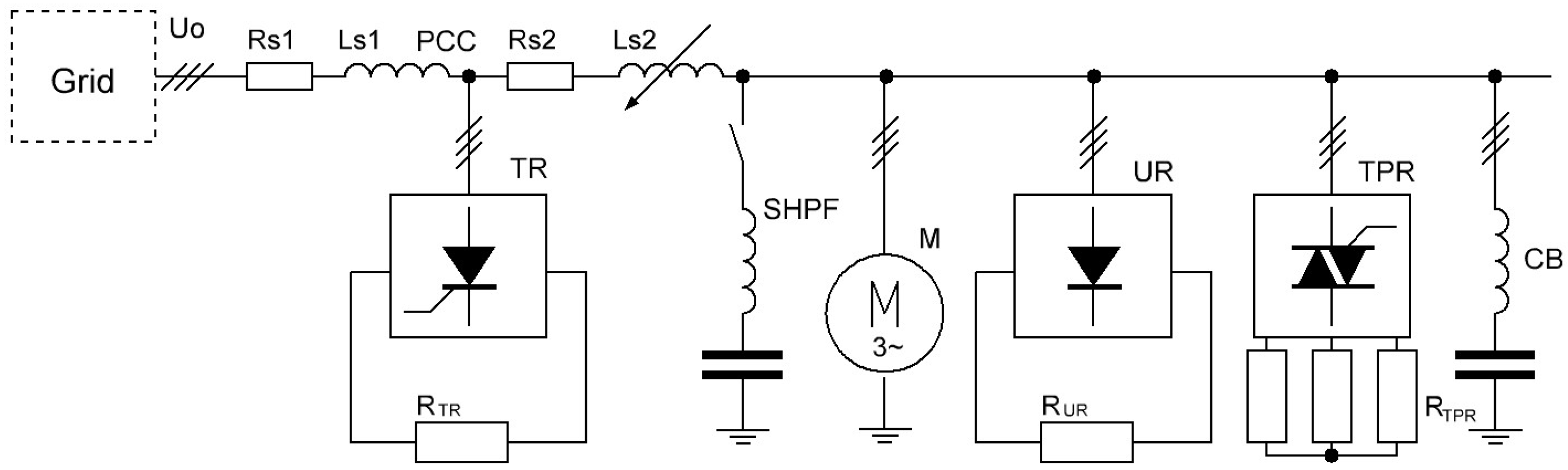
Figure 4.
The dependence of consumer load contributions on the supply feeder impedance (RTR = 20 Ω).
Figure 4.
The dependence of consumer load contributions on the supply feeder impedance (RTR = 20 Ω).
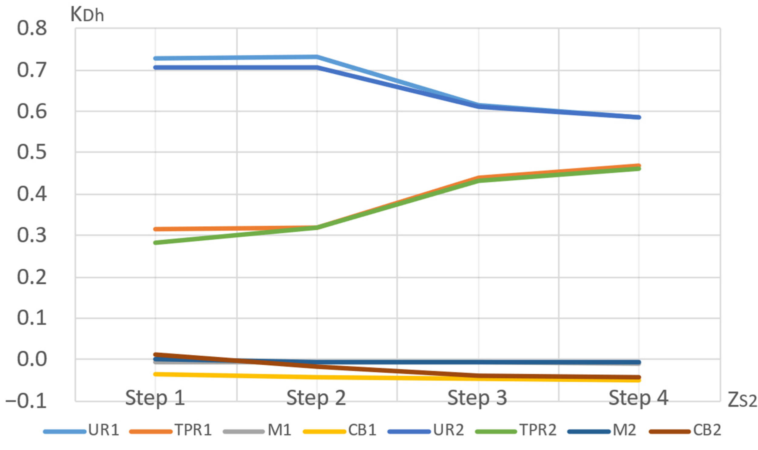
Figure 5.
The dependence of the external source contribution TR on the resistance of the nonlinear load TR for different supply feeder impedance values.
Figure 5.
The dependence of the external source contribution TR on the resistance of the nonlinear load TR for different supply feeder impedance values.

Figure 6.
The dependences of the relative value of SPHF harmonic currents ΔIFh on RTR for different modes of electrical load and supply feeder impedance in Step 1.
Figure 6.
The dependences of the relative value of SPHF harmonic currents ΔIFh on RTR for different modes of electrical load and supply feeder impedance in Step 1.

Figure 7.
The dependence of the RMS current ratio, taking into account the maximum and real addition, on the power of the external distortion source TR.
Figure 7.
The dependence of the RMS current ratio, taking into account the maximum and real addition, on the power of the external distortion source TR.
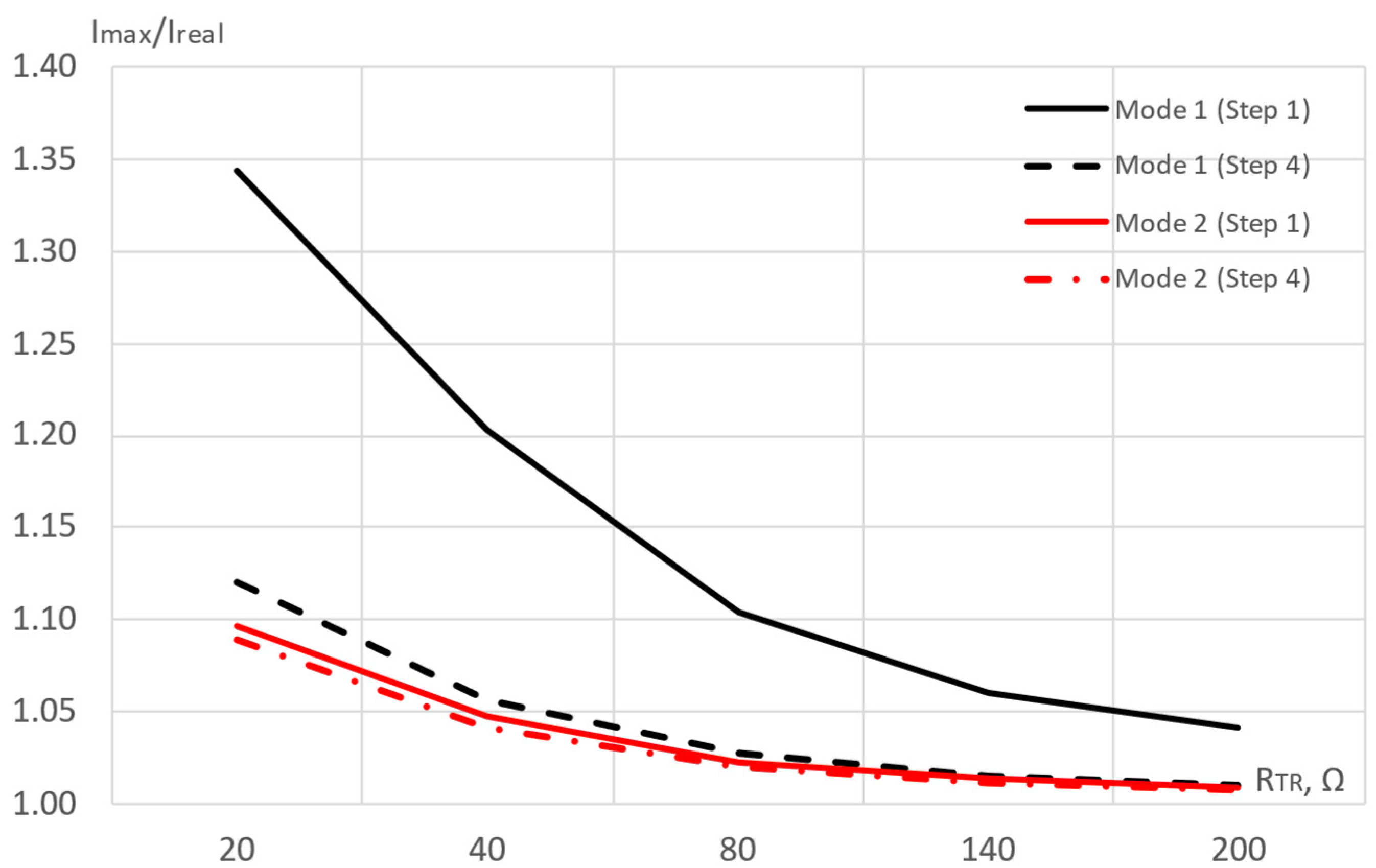
Figure 8.
The simplified equivalent electrical schemes with connected SPHF and background harmonic distortions represented as a current harmonic source (a) and a voltage harmonic source (b).
Figure 8.
The simplified equivalent electrical schemes with connected SPHF and background harmonic distortions represented as a current harmonic source (a) and a voltage harmonic source (b).

Table 1.
The parameters of the equivalent circuit.
| Elements of the Scheme | Parameters and Values |
|---|---|
| Grid | U0 = 0.4 kV, RS1 = 0.18 Ω, LS1 = 1.75 mH |
| Supply feeder ZS2 (step 1) | Step 1: RS2 = 0.22 Ω, LS2 = 1.71 mH Step 2: RS2 = 0.83 Ω, LS2 = 4.8 mH Step 3: RS2 = 1.0 Ω, LS2 = 10.96 mH Step 4: RS2 = 1.49 Ω, LS2 = 14.73 mH |
| Induction motor (M) | UM = 0.38 kV, PM = 1.5 kW, η = 76%, cosφ = 0.74 |
| Thyristor rectifier (TR) | UTR = 0.38 kV, RTR = [20; 200] Ω |
| Thyristor power regulator (TPR) | UTPR = 0.38 kV, RTPR = 32.3 Ω |
| Uncontrolled rectifier (UR) | UUR = 0.38 kV, RUR = 96.8 Ω |
| Capacitor banks (CB) | 4 step of regulation, QCB1 = 0.5 kvar, ftuned = 134 Hz |
| Passive harmonic filter (SPHF) | LF = 14.1 mH, CF = 31 μF, ftuned = 241 Hz |
Table 2.
Simulation parameters.
| Stage Number | TR | UR | TPR | M | CB | Variation Parameters | |
|---|---|---|---|---|---|---|---|
| ZS2 | RTR, Ω | ||||||
| 1 and 2 | + | + | + | + | + | Step 1–Step 4 | [20; 200] |
| 3 (mode 1) | + | + | + | + | + | ||
| 3 (mode 2) | + | − | + | + | + | ||
| 3 (mode 3) | + | + | − | + | + | ||
Table 3.
The error values of the UR and TPR share contribution calculated according to Equation (11).
Table 3.
The error values of the UR and TPR share contribution calculated according to Equation (11).
| RTR | δKDh (UR), % | δKDh (TPR), % | ||||||
|---|---|---|---|---|---|---|---|---|
| Step 1 | Step 2 | Step 3 | Step 4 | Step 1 | Step 2 | Step 3 | Step 4 | |
| 20 | 3.0 | 3.6 | 0.8 | 0.2 | 9.7 | 0.6 | 1.4 | 1.1 |
| 80 | 0.4 | 0.8 | 0.2 | 0.1 | 2.1 | 0.3 | 0.1 | 0.2 |
| 140 | 0.2 | 0.4 | 0.1 | 0.1 | 1.2 | 0.2 | 0.1 | 0.1 |
| 200 | 0.1 | 0.3 | 0.1 | 0.1 | 0.9 | 0.2 | 0.1 | 0.1 |
Table 4.
SPHF harmonic currents with the same types of rectifiers in the scheme.
| RTR | IFh_0, A | IFh_2, A | IFh_0 + IFh_2, A | IFh_1, A | δ1, % | δ 4, % | ||||
|---|---|---|---|---|---|---|---|---|---|---|
| Step 1 | Step 4 | Step 1 | Step 4 | Step 1 | Step 4 | Step 1 | Step 4 | Step 1 | Step 4 | |
| 20 | 1.611 | 1.751 | 1.761 | 0.446 | 3.372 | 2.197 | 3.271 | 2.016 | 3.00 | 8.24 |
| 40 | 0.902 | 0.23 | 2.513 | 1.981 | 2.450 | 1.860 | 2.51 | 6.11 | ||
| 80 | 0.457 | 0.117 | 2.068 | 1.868 | 2.031 | 1.787 | 1.79 | 4.34 | ||
| 140 | 0.263 | 0.067 | 1.874 | 1.818 | 1.851 | 1.764 | 1.23 | 2.97 | ||
| 200 | 0.185 | 0.047 | 1.796 | 1.798 | 1.779 | 1.758 | 0.95 | 2.22 | ||
Table 5.
Comparison of calculation results according to Equation (15) and simulation results.
| KSC | Ssc1, kVA | I3h_meas, A | fr | IFh_meas, A | IFh_calc, A | δI, % |
|---|---|---|---|---|---|---|
| 2.00 | 250 | 4.82 | 0.966 | 1.855 | 1.938 | −4.48 |
| 3.97 | 4.78 | 1.092 | 1.083 | 0.83 | ||
| 7.19 | 4.76 | 0.601 | 0.628 | −4.49 | ||
| 9.40 | 4.75 | 0.470 | 0.488 | −3.84 |
Disclaimer/Publisher’s Note: The statements, opinions and data contained in all publications are solely those of the individual author(s) and contributor(s) and not of MDPI and/or the editor(s). MDPI and/or the editor(s) disclaim responsibility for any injury to people or property resulting from any ideas, methods, instructions or products referred to in the content. |
© 2024 by the authors. Licensee MDPI, Basel, Switzerland. This article is an open access article distributed under the terms and conditions of the Creative Commons Attribution (CC BY) license (https://creativecommons.org/licenses/by/4.0/).
Share and Cite
MDPI and ACS Style
Skamyin, A.; Shklyarskiy, Y.; Gurevich, I. Influence of Background Voltage Distortion on Operation of Passive Harmonic Compensation Devices. Energies 2024, 17, 1342. https://doi.org/10.3390/en17061342
AMA Style
Skamyin A, Shklyarskiy Y, Gurevich I. Influence of Background Voltage Distortion on Operation of Passive Harmonic Compensation Devices. Energies. 2024; 17(6):1342. https://doi.org/10.3390/en17061342
Chicago/Turabian StyleSkamyin, Aleksandr, Yaroslav Shklyarskiy, and Ilya Gurevich. 2024. "Influence of Background Voltage Distortion on Operation of Passive Harmonic Compensation Devices" Energies 17, no. 6: 1342. https://doi.org/10.3390/en17061342
Note that from the first issue of 2016, this journal uses article numbers instead of page numbers. See further details here.