
Ash Formation and Associated Interactions during Co-Combustion of Wheat Straw and Sewage Sludge

School of Energy and Environment, Southeast University, Nanjing 210096, China
*
Author to whom correspondence should be addressed.
Energies 2024, 17(6), 1486; https://doi.org/10.3390/en17061486
Submission received: 20 February 2024
/
Revised: 13 March 2024
/
Accepted: 17 March 2024
/
Published: 20 March 2024
(This article belongs to the Section I2: Energy and Combustion Science)
Abstract
:The aim of the present work was to investigate ash formation and associated interactions during the pulverized fuel co-combustion of biomass fuels. Combustion experiments were carried out with narrowly sized wheat straw (WS), sewage sludge (SS), and their blends in a drop tube furnace at 1100 °C and 1300 °C. The resulting residual ash and fine particulate matter (PM10) were characterized with various analyses. It was observed that co-combustion influences size distributions of the residual ash particles and generally generates larger residual ash particles close to those of SS combustion. The interaction of K capture by minerals enhances the melting and consequently increases the production of large and melting ash particles during co-combustion. It was found that blending SS with WS has not only the positive interaction of K capture by minerals from SS ash to significantly reduce submicron ash formation, but also the positive interaction of transforming alkali chlorides into alkali sulfates to reduce the corrosiveness of submicron ash particles. Co-combustion of SS with WS can also reduce the presence of alkali chloride at PM1–10, lowering the propensities of deposition and corrosion of the fine residual ash particles.
1. Introduction
As a low-carbon and renewable fuel, biomass can be utilized for the decarbonization of existing coal-fired power plants by partially and even fully replacing coal for combustion [1]. Further combinations with carbon capture and storage technology are promising to achieve negative CO2 emission [2]. Biomass firing, including co-firing and sole biomass combustion, has been developed and practiced globally over the past two decades. It is currently attracting increasing interest in China for applications in pulverized coal-fired power plants [3,4], aiming to reduce CO2 emissions and develop a gradual transition away from coal power generation.
Co-firing biomass at relatively high ratios, particularly sole biomass combustion in pulverized fuel power plants, often uses high-quality fuels, mostly woody biomass such as wood pellets [5]. But the high cost, competitive supply, and sustainability concern associated with such fuels [5] drive the use of alternative fuels, mainly non-woody biomass from agricultural residues and waste streams [6]. For example, agricultural residues [4] and sewage sludge [7] are the most often and widely used biomass fuels in China. Compared to woody biomass, however, agricultural residues such as straw generally have higher ash, alkali metal, and chlorine contents [6,8,9], which can cause the slagging, fouling, and corrosion of heat exchange surfaces in pulverized fuel combustion systems [10]. These ash-related operational problems may limit co-firing ratios and make pure biomass combustion rather difficult [11]. To tackle these ash-related problems, technologies including fuel pretreatments, using additives, and fuel co-combustion are proposed [12,13,14]. Among them, the co-combustion of different biomass fuels such as wood and straw has been practiced [11], taking advantages of the positive interactions in the ash formation and behavior of the different fuels [15].
During pulverized fuel combustion, complex interactions occur among ash forming components, affecting ash formation and behavior. Notable interactions are the gas–gas reactions of vaporized ash forming species and gas–solid reactions between the vaporized species and ash particles. For biomass combustion, the vaporized species are mainly the ash forming elements released from the fuel into the gas phase, including alkali metals, Cl, S, and P [16]. They mostly transform into submicron ash particles, which have critical impacts on ash deposition [17,18] and corrosion [19,20,21]. The associated positive interactions include alkali sulfation, alleviating ash corrosiveness [21,22,23], and alkali capture by silicates/aluminosilicates, reducing ash deposition [24]. Such interactions are motivated by using additives to mitigate ash-related problems [14].
It is well known that biomass fuels have various ash compositions and, particularly, high contents of vaporable elements [25,26]. The co-combustion of biomass fuels with a distinct ash composition is expected to accompany strong interactions between ash forming compounds from the individual fuels. There is therefore potential to select other biomass fuels for enhancing positive interactions to facilitate the utilization of non-woody fuels. For such a circumstance, understanding the interactions and their impacts on ash formation and behavior is essential. Extensive studies have been conducted to investigate the interactions of ash formation and especially submicron ash formation during pulverized biomass combustion [27,28] and biomass co-firing with coal [29,30]. In contrast, few studies have specifically addressed the interactions of ash formation during the pulverized fuel co-combustion of biomass fuels [15]. The objective of the present work was to investigate ash formation during the pulverized fuel co-combustion of agricultural residues with other biomass. Wheat straw was used as a representative of agricultural residues, while municipal sewage sludge was selected for co-combustion. Based on combustion experiments and resulting ash characterization, this study focused on exploring the interactions in ash chemistry and their impacts on residual and submicron ash formation during co-combustion.
2. Materials and Methods
2.1. Preparation of Fuel Samples
Wheat straw and municipal sewage sludge were used as raw materials in this study. The wheat straw was received from Lianyungang, Jiangsu Province, and sewage sludge was collected from Nanjing urban sewage treatment plant. The raw materials were dried, pulverized, and sieved to obtain size fractions of 100–200 μm for the experiments. The results of their proximate and ultimate analyses as well as lower heating values are presented in Table 1, and elemental compositions of their laboratory ashes are shown in Table 2. The narrowly sized wheat straw (WS) and sewage sludge (SS) were then blended in three ratios, i.e., 20%, 40%, and 60% SS with WS by mass. The resulting blends and their parent samples were used for combustion experiments. The blends are named with their compositions. For example, the mixture of 80% WS and 20% SS is called WS80-SS20. The WS and SS have the fuel properties of typical straw biomass and sludge waste, respectively. The WS has higher volatile matter and lower ash contents and much higher heating value (Table 1), and therefore has better combustion characteristics than the SS, providing a synergistic effect for the co-combustion of the two fuels. In particular, the SS has a much higher ash content and is expected to dominate ash formation during co-combustion. Moreover, the two fuels have distinctly different ash compositions (Table 2). The WS ash has high contents of Si, K, and Cl, and the SS ash is relatively rich in Si, Al, Ca, Fe, and P (Table 2), suggesting potential interactions in ash chemistry during co-combustion.
2.2. Combustion Experiments
WS, SS, and their blends were burned in a high-temperature drop tube furnace (DTF), as shown schematically in Figure 1. The DTF system is composed of a micro-feeder, a gas supply subsystem, a reaction tube and its heating furnace, and a sampling subsystem. The key component of the DTF is a corundum tube with a length of 1600 mm and an inner diameter of 48 mm. The tube is heated by three-section electric heating elements (450 mm each). The tube wall temperatures are measured by three thermocouples at the midpoint of each section and monitored for controlling the heating to achieve an isothermal length of approximately 1200 mm. During the experiment, fuel particles were delivered by the micro-feeder, carried by primary air and further mixed with secondary air, and then entered the reaction tube to undergo combustion through a water-cooled probe inserted in the top of the DTF tube. The products including the flue gas and ash particles were extracted at the bottom of the reaction tube by a nitrogen-quenched, water-cooled sampling probe, and then directed to a glass-fiber filter (sampling line B in Figure 1) to collect bulk ash particles or sampling line A to sample fine particulate matter (PM). Sampling line A consists of a cyclone with an aerodynamic cut-off size of 10 μm to remove larger particles and a 14-stage electric low pressure impactor (ELPI) (ELPI+, Dekati, Finland) to size-segregate fine PM and measure the particle concentrations and particle size distribution (PSD) of the fine PM in real time. Both sampling lines were kept at 105 °C to avoid the impact of the possible condensation of acid gases and moisture in the flue gas on the sampling and measurement of solid particles [31]. The collected bulk ash particles by the filter or fine PM samples by ELPI stages were subjected to the subsequent characterization.
The combustion of the three blends and their parent fuels was conducted in an air atmosphere (21% O2/79% N2) at two furnace temperatures of 1100 °C and 1300 °C. The feeding rate of the fuel was set at ca. 0.05 g/min, and the mass flow rates of the primary and secondary air were around 1 and 4 L/min, respectively. The air flow rates were slightly adjusted so as to maintain the reaction residence time of ca. 1.5 s for all fuels. The combustion conditions were controlled by setting the air fuel ratios to be similar, i.e., ca. 129, for all fuels, while the resulting excess air ratios were quite different. Nevertheless, the very high excess air ratios (e.g., 29.2 and 41.0 for sole WS and SS combustion) together with the maintained residence time ensure the burnout of fuel particles in all combustion cases, enabling the investigation of ash formation in the context of complete fuel combustion, and also avoiding extensive particle–particle interactions (collisions) during ash formation stages, which do not prevail in practical pulverized fuel combustion systems.
2.3. Characterization of Ash Samples
Filter-collected residual ashes from the combustion experiments as well as the parent fuels (WS and SS) were analyzed by laser diffraction (Malvern Mastersizer 2000, Malvern Panalytical, Malvern, England) with a wet (ethanol) method to determine their PSDs. The residual ashes were also examined by scanning electron microscopy (SEM) to observe the particle morphology. Additionally, X-ray diffraction (XRD) analyses were performed to identify crystalline phases in the residual ashes so as to investigate the transformations of main inorganic components of the biomass and related effects by the interactions during ash formation. As for the PM samples, the concentrations and PSDs of PM10 (particulate matter with an aerodynamic diameter of <10 μm) from the combustion were measured in situ by ELPI+. Moreover, PM particles collected in the ELPI stages were analyzed by SEM equipped with an energy-dispersive X-ray spectroscopy (EDS) detector to determine the elemental composition. Accordingly, the mass concentrations and elemental compositions of PM1 (particulate matter with an aerodynamic diameter of <1 μm, i.e., submicron ash collected in ELPI stages 1–9) and PM1–10 (particulate matter with an aerodynamic diameter of 1–10 μm, i.e., supermicron ash collected in ELPI stages 10–14) were estimated by weighted calculations.
3. Results and Discussion
3.1. Characteristics of the Residual Ash Formation
3.1.1. PSDs and Morphology of the Residual Ashes
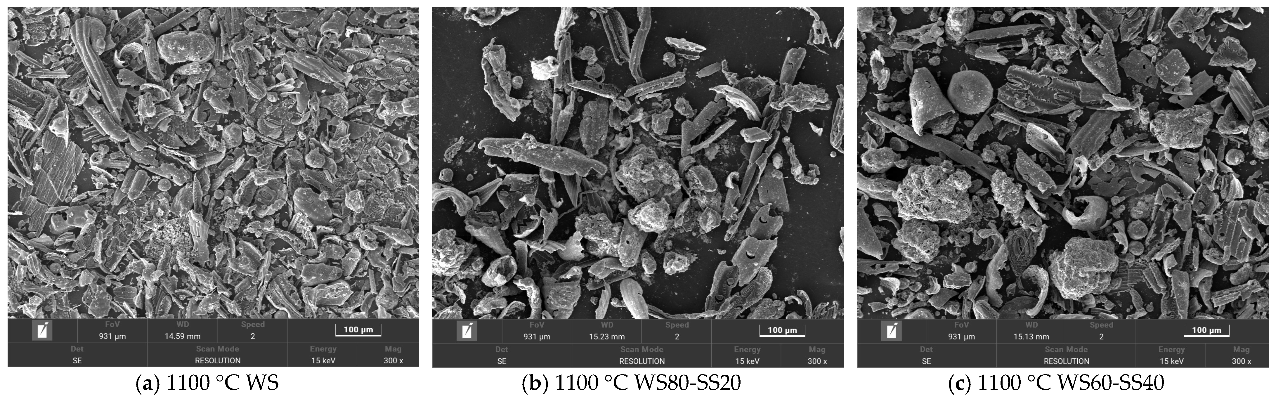
The PSDs of the residual ashes from WS and SS burning at two temperatures are presented in Figure 2, compared with the PSDs of WS and SS. SEM observations of the WS and SS ash particles are shown in Figure 3. It can be seen in Figure 2a that the PSD of WS appears as a bimodal distribution with a large mode at ca. 200 μm and a tiny peak at 22 μm. Most WS particles are much larger than the sieve size, i.e., 100–200 μm, because WS particles are generally elongated and pass through the sieve in their smallest dimension [32]. After combustion, the sizes of the residual ash particles are greatly reduced relative to WS particles, resulting in the ash PSDs shifting to the small-sized side of the WS PSD. This is attributed to the particle fragmentation and shrinkage/coalescence during ash particle formation [33]. While the WS ashes produced at the two temperatures have similar PSDs, both as a single mode of distribution, the 1300 °C ash is slightly smaller in size than the 1100 °C ash (Figure 2a). It was noted that laboratory WS ash has a very low melting temperature (940 °C). However, SEM observation shows that the ash particles generated at 1100 °C are mostly irregular in shape (Figure 3a), and even the 1300 °C ash has only a small fraction of spherical particles formed due to ash melting and coalescence (Figure 3f). The reason is that while the easily vaporized fraction of the inorganic matter in WS particles, mostly alkali species, is released into the gas phase during combustion, the fraction left to transform into residual ash particles generally has much higher melting temperature. As a result, the extent of ash melting is not significant even at 1300 °C, and particle fragmentation is more preferential in the last stages of combustion [8] to generate irregular ash particles. Nevertheless, higher temperatures increase the extent of melting, favoring ash coalescence during ash particle formation to produce slightly smaller ash particles at 1300 °C than at 1100 °C (Figure 2a).
Figure 2b displays the PSD of SS, seeming to be a single mode of distribution, peaking at 80 μm but with a broad shoulder on the smaller side. Most of the SS particles are much smaller than the sieve size, reflecting the difficulty of the sieve to remove small particles. Compared to the WS particles, the SS particles are generally smaller in volumetric size, mostly because of their near-spherical shapes, significantly different from the elongated shapes of the WS particles. Figure 2b shows that the PSDs of the SS ashes formed at two temperatures are also similar, presenting a two-mode distribution with a large peak at ca. 125 μm and a tiny peak at ca. 20 μm. The small-mode particles were likely produced by fine fragmentation as the large particles burned and during the burnout of small SS particles, whereas the large-mode particles were formed by ash melting/coalescence. In contrast to those of WS ash formation, the PSDs of the SS ashes shifted and concentrated on the larger side of the SS PSD. Moreover, most of the SS ash particles are larger, with a narrower size distribution concentrating around the peak of ca. 125 μm, implying the occurrence of swelling during ash particle formation. The reason is that, although the laboratory SS ash has a much higher melting temperature (1287 °C) than laboratory WS ash, the burning temperatures of the SS particles during char conversion stages may overshoot the furnace temperatures and be higher than the ash melting point, even for the combustion at 1100 °C. Consequently, melting/coalescence is more preferential than fragmentation to form large ash particles, and swelling may also occur during ash particle formation. The morphology of the 1100 °C ash particles in Figure 3e shows that the large particles are irregular but nearly spherical, indicating softening during ash formation, and the large particles also have bubbles and holes on the surfaces, suggesting the occurrence of swelling. The presence of a large fraction of spherical particles in the 1300 °C ash (Figure 3j) reflects the effect of a higher extent of melting on ash particle formation. Increasing the furnace temperature from 1100 °C to 1300 °C enhances ash melting and is therefore more favorable for ash coalescence and unfavorable for particle fragmentation, leading to the formed 1300 °C ash particles having a size distribution with a narrower and higher large particle peak and a narrower and lower small particle peak than the 1100 °C ash particles, as shown in Figure 2b. Comparing the PSDs of the WS and SS ashes and their dependences on the combustion temperature in Figure 2 reveals that the evolutions of the residual ash PSDs and ash formation behaviors between the two fuels are distinctly different. Nevertheless, it is likely to offer the possibility to observe the gas–solid interactions of ash chemistry and their impact on residual ash formation during the co-combustion of the two fuels.
Figure 4 presents the PSDs of the residual ashes from the co-combustion of WS and SS at two temperatures. As can be seen in Figure 4a, the measured PSDs of the 1100 °C ashes from WS60-SS40 and WS40-SS60 are very close to that of the SS ash. This was expected because of the higher ratios of SS, which has much higher ash content than WS (Table 1). The measured PSD of the 1100 °C ash from WS80-SS20 is more similar to that of the WS ash but, surprisingly, the ash particle of this blend is considerably finer than the WS ash. Figure 4b shows that the measured PSDs of the ashes from the blends burning at 1300 °C lay between those of the WS and SS ashes. By increasing the blending ratio of SS, the PSD of the blend ash gradually comes close to that of the SS ash, indicated by the gradual decrease in 20–70 μm particles and the increase in particles around the coarse mode.
To explore if there is any synergistic effect on residual ash formation during WS and SS co-combustion, the PSDs were additively calculated for the blend ashes. Assuming the residual ash formation of the individual fuels to be independent during co-combustion, the PSD of a blend ash was calculated by weighting the PSD of the ashes generated from the combustion of the individual fuels at the same temperature, based on the ratios of the ashes of the two fuels in the blend. The results are also presented in Figure 4 for comparison. It can be seen that, for the cases of co-combustion at 1100 °C, the calculated PSDs of the WS60-SS40 and WS40-SS60 ashes are generally broader but with smaller ash particles than the measurements; however, the difference between the calculated and measured PSD of the WS80-SS20 ash is reversed. For the ashes from co-combustion at 1300 °C, the calculated PSDs are generally more concentrated around the coarse mode, with a higher and sharper peak, but also higher in the fine fragmentation mode as compared to the corresponding measured PSDs. In a word, the comparisons in Figure 4 show the differences between the measured and calculated PSDs of the blend ashes, implying possible synergistic interactions affecting residual ash formation during WS and SS co-combustion. This will be further discussed.
3.1.2. XRD Analysis of the Bulk Ashes
To investigate the transformations of inorganic matter and possible interactions during the residual ash particle formation of WS and SS co-combustion, XRD was employed to analyze crystalline phases in the bulk ashes from burning the blends and parent fuels. The obtained XRD spectra and crystalline phases identified are compiled in Figure 5.
As can be seen in Figure 5, the crystalline phase in the 1100 °C WS ash is solely sylvite (KCl), while quartz (SiO2) is also detected in the 1300 °C WS ash. These are expected because K, Cl, and Si are the dominant elements in WS ash (Table 2). During combustion, KCl occurs or is formed in ash, while SiO2 in the WS is transformed into the crystalline phase, quartz, at higher temperatures [34]. In the 1100 °C SS ash, the minerals detected primarily included quartz, AlPO4, and K- and Ca-aluminosilicates, consistent with the high contents of Si, Al, P, and Ca in SS (Table 2), as well as minor species of Ca-Fe-Mg silicates, hematite, and CaSO4. In the 1300 °C SS ash, the minor minerals and some aluminosilicates disappear and probably transform into the glass phase, indicated by ash particles melting at the higher temperature (Figure 3).
The XRD spectra of the ashes from WS60-SS40 and WS40-SS60 burning at the two temperatures mostly resemble those of the SS ashes because SS ash dominates in the blend ashes. KCl is observed in the ashes of WS80-SS20 at the two temperatures, obviously originating from the WS ash. In particular, KAlSi3O8 with relatively stronger peak intensities is observable in the ashes of WS60-SS40 burning at the two temperatures. This suggests the production of KAlSi3O8 during the combustion of the blend due to the aluminosilicates from the SS capturing potassium, mostly from the WS. A previous study [35] also noticed the introduction of sewage sludge into wheat straw increasing the retention of potassium in the residual ash. It implies the occurrence of a gas–solid interaction, which affected the ash formation during the co-combustion of the two fuels.
Considering the interaction of potassium capture and its reaction products, it can be found in Figure 5b that KCl is present in the WS80-SS20 ash but is almost undetectable in the WS60-SS40 and WS40-SS60 ashes, while KAlSi3O8 is not detected in the WS80-SS20 ash but occurs in the WS60-SS40 and WS40-SS60 ashes. This means that, while it may not be fully captured or converted in the WS80-SS20 ash, KCl is nearly fully transformed into KAlSi3O8 during co-combustion with a higher SS blending ratio. Alkali capture is capable of enhancing the melting of aluminosilicate minerals in ash [36], therefore promoting the melting/coalescence but reducing the fragmentation of ash particle formation. This explains why the measured PSDs of the ashes from the combustion of the blends at 1300 °C are generally broader but with less small particles than the calculated ones (Figure 4b). For the ash formation of co-combustion at 1100 °C, potassium capture and its enhanced melting may still play the role as indicated by the large swelling particles in Figure 3d, leading the measured PSDs of the ashes from the blends with higher ratios of SS to be narrower and sharper than the calculated ones (Figure 4a). However, the XRD analyses indicate that the presence of KCl in the WS80-SS20 and WS60-SS40 ashes and the weak peaks of KAlSi3O8 in these blend ashes (Figure 5a) may suggest weaker potassium capture and transformation due to the lower reaction temperature, particularly for WS80-SS20 combustion. As a consequence, the effect of enhancing melting and coalescence is not so strong, allowing more particle fragmentation, particularly for WS in WS80-SS20 combustion, as shown in Figure 3b, to form more small ash particles than the calculation (Figure 4a). Nevertheless, co-combustion generally forms larger residual ash particles close to those of SS combustion (Figure 4). Moreover, K capture enhances melting, which increases the production of large and melting ash particles (Figure 3) during co-combustion, which may increase the propensity of these particles to form slag in pulverized fuel combustion systems. Such an effect is worthy of further study.
3.2. The Formation of PM10
3.2.1. PSD and Production of PM10
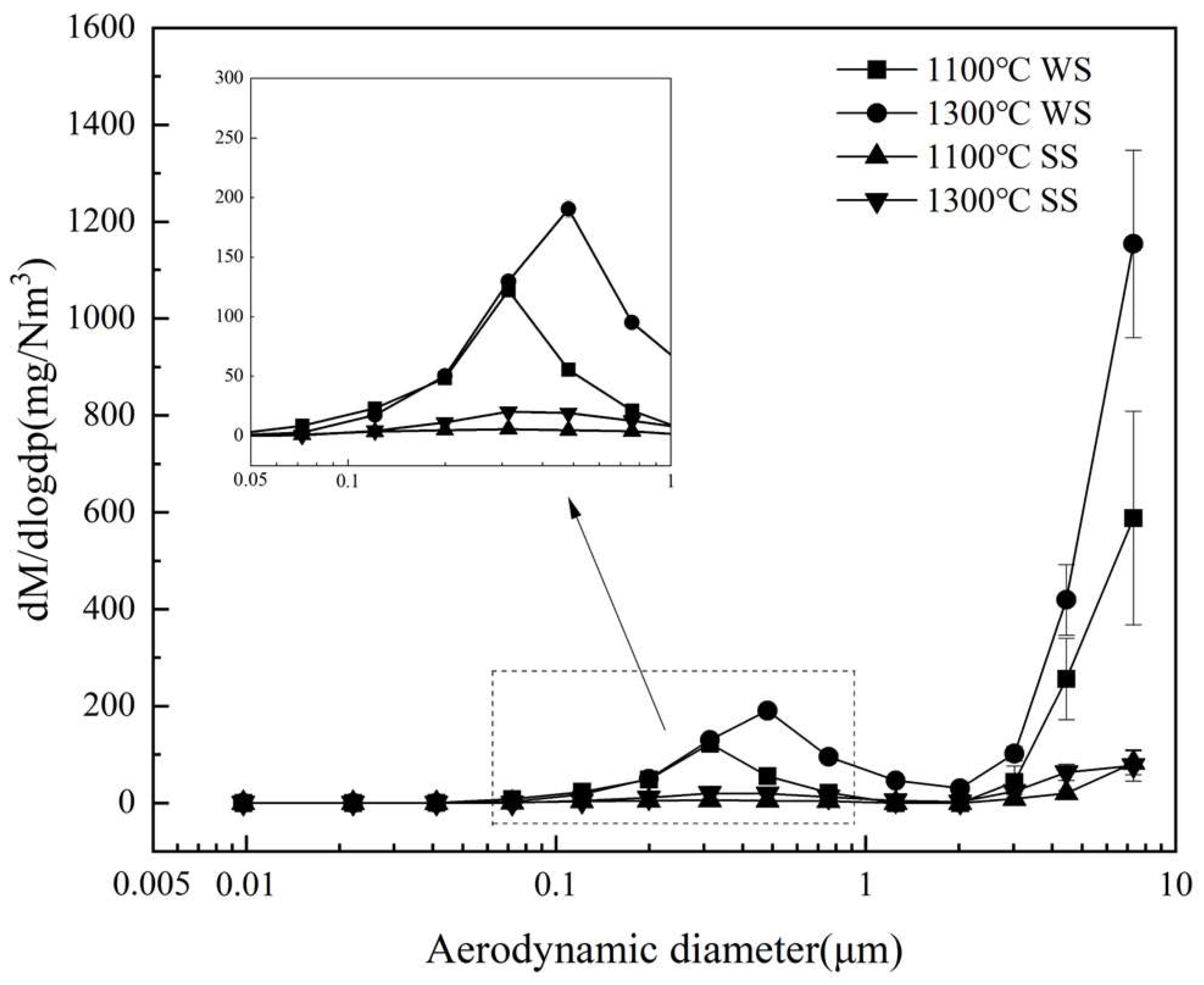
Figure 6 illustrates the ELPI-measured, mass concentration-based PSDs of the PM10 produced from burning WS and SS at two temperatures. Clearly, the PSDs all display a bimodal pattern, with a submicron mode located between 0.3 and 0.5 μm and a supermicron mode of particles larger than 2 μm, typical of PM10 generated from pulverized biomass combustion [37,38]. The productions of both submicron and supermicron particles from WS combustion are much higher than those from SS combustion. Increasing the combustion temperature from 1100 °C to 1300 °C increases the formation of submicron particles and leads to the shift of the mode diameter from 0.31 to 0.48 μm for WS and SS combustion. The reason is that higher temperature promotes the vaporization of inorganic matter during combustion [16], resulting in subsequently forming more PM1 and enhancing the growth of submicron particles by coagulation and condensation. Elevating the temperature also considerably increases the yield of supermicron particles from WS combustion.
The PSDs of PM10 generated from the combustion of three blends at 1300 °C are shown in Figure 7a, where those from burning WS and SS are represented for comparison. As can be seen, the PSD profiles of the blend ashes are similar to those of PM10 from burning the individual fuels. As the blending ratio of SS increases, the production of PM10 generally decreases, reflected by the continuous decline in the submicron peak and general reduction in supermicron particles. This suggests that blending SS with WS reduces PM10 and especially PM1 production. Increasing the furnace temperature from 1100 °C to 1300 °C also enhances the production of both submicron and supermicron particles, as shown in Figure 7b, with the results from WS80-SS20 combustion as an example.
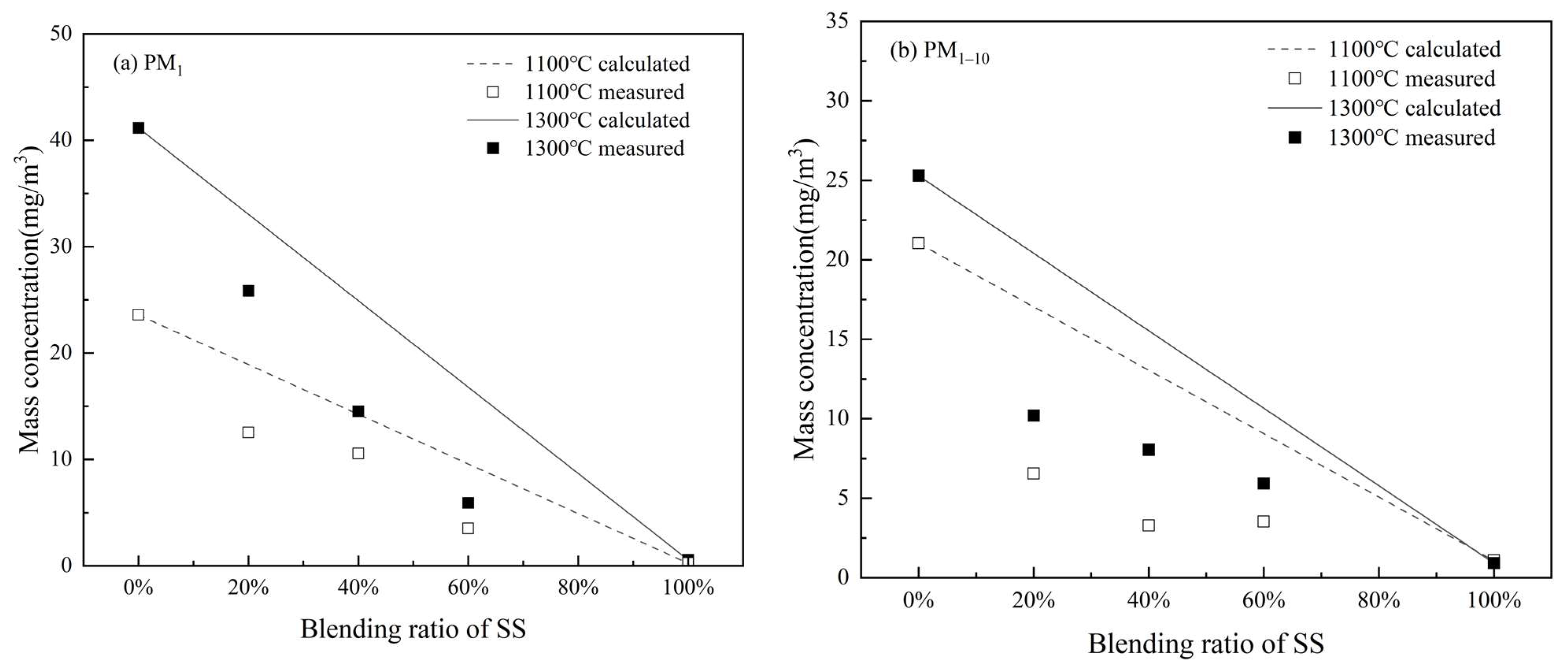
To quantify the effect of the blending ratio on PM10 production, cumulative yields of PM1 and PM1–10 from all experimental cases are summarized in Figure 8. It is clear that the PM1 yield decreases monotonously with increasing the blending ratio of SS for combustion at both temperatures (Figure 8a). Decreasing trends are also observable for the PM1–10 yields (Figure 8b). These are expected because of the dilution effect, where SS combustion produced much less PM10 and PM1 than WS combustion. Moreover, when compared to the theoretical yields, assuming the PM1 yield of a blend to be the additive sum of the PM1 productions from the individual fuels and denoted as the lines in Figure 8a, the measured PM1 yields from burning the blends are significantly lower, evidencing further PM1 reduction during co-combustion. Relative to the theoretically calculated values, the PM1 yield is reduced by 18.6%, 28.1%%, and 37.5% for the co-combustion of WS with 20%, 40%, and 60% SS at 1100 °C, respectively. The reductions are more significant at the higher temperature, i.e., 1100 °C (Figure 8a). The reduction is 21.1%, 34.3%, and 50.8% for the co-combustion of WS with 20%, 40%, and 60% SS, respectively. Such reductions imply the synergistic effect of the interaction reactions between submicron ash forming species from the parent fuels, which is discussed further in the following paragraph. In contrast, the measured PM1–10 yields scatter around the additive lines (Figure 8b), suggesting little synergistic effect on supermicron PM formation.
3.2.2. Elemental Composition of PM10
The EDS-measured elemental compositions of PM1 and PM1–10 from burning WS, SS, and their three blends at two temperatures are compiled in Figure 9. The compositions are the weighted averages of the particles collected in ELPI stages 1–9 and 10–14, respectively. As can be seen, K and Cl dominate the PM1 in WS combustion and their contents have no considerable change with the combustion temperature. In contrast, the PM1 in SS combustion is composed of the volatile elements K, Na, Cl, S, and P and the refractory elements Si, Al, Ca, and Fe, with K, S, P, and Si relatively dominating. As the temperature increased from 1100 °C to 1300 °C, the contents of K, Si, and S increased and that of P declined relatively. The composition of PM1–10 from WS combustion resembles that of the laboratory ash except for significantly lower K and Cl contents. Raising the combustion temperature increases the contents of K, S, and P, probably because higher temperatures enhance the release of these elements during combustion and they re-condense on or are captured by the fine residual ash particles, i.e., PM1–10 during ash formation. The compositions of PM1–10 from SS combustion are similar to that of the laboratory ash and are not considerably affected by the combustion temperature.
Figure 9a exhibits that the compositions of PM1 from the 1100 °C combustion of the blends are close to that of WS combustion, still dominated by K and Cl. No clear trend is observable for the influence of the blending ratio. As can be seen in Figure 9c, the compositions of PM1 from the 1300 °C combustion of the blends are also still relatively close to that of WS combustion. However, with increase in the SS blending ratio, the contents of K and particularly Cl decrease, while those of Na, S, P, and Si increase. The compositions of PM1–10 from the blends burning at two temperatures are generally similar to that of SS combustion (Figure 9b,d), suggesting that the SS in the blends dominate PM1–10 formation in contrast to WS controlling PM1 formation. The blending ratio has an unnoticeable influence on PM1–10 composition. Higher combustion temperatures generally increase the contents of K, Cl, and S in the PM1–10.
Figure 9 indicates that PM1 formed from co-combustion is mostly composed of K, Cl, S, and P, among which S and P originate mostly from SS and K and Cl from WS. This implies that the gas–gas and gas–solid interactions during ash formation may occur to affect these elements transforming into PM1 during co-combustion. Numerous studies [19,29,39] have demonstrated that submicron ash particles from biomass combustion consist of primarily alkali chlorides and sulfates as well as phosphates. To explore the possible interactions and their impacts, the molar ratios of the major elements forming the salts in the PM1 were examined. The calculated molar ratios for all the PM1 samples are summarized in Table 3, where P is counted as a monovalent, considering that alkali metaphosphates rather than phosphates are present dominantly in PM1 [40].
Table 3 indicates that, for all PM1 samples, the (Na + K)/(Cl + 2S) ratios are close to 1.0, confirming that PM1 is composed of mostly alkali chlorides and sulfates; the (Na + K)/(Cl + 2S + P) ratios are also mostly close to 1.0, suggesting the occurrence of alkali phosphates in PM1, but its contribution not significant. For PM1 generated from WS combustion, its (Na + K)/Cl ratios are close to 1.0, while the (Na + K)/2S and (Na + K)/(2S + P) ratios are much higher than 1.0. These suggest WS PM1 is exclusively composed of alkali chlorides. In contrast, for PM1 formed from SS combustion, while their (Na + K)/Cl ratios are greatly higher than 1.0, the (Na + K)/2S and (Na + K)/(2S + P) ratios are nearly 1.0, reflecting that alkali sulfates as well as phosphates are dominant.
For PM1 from co-combustion, the (Na + K)/Cl ratios are higher than, but not far from, 1.0, particularly for the PM1 formed at the lower temperature, suggesting that chlorides are still the dominant alkali salts. However, the (Na + K)/Cl ratio gradually increases and the (Na + K)/2S and (Na + K)/(2S + P) ratios greatly decrease with increasing the blending ratio of SS. This implies that S and P from SS partially replace Cl from WS to form alkali salts, contributing to submicron ash formation. The effect of such an interaction is more profound in the PM1 formation at higher-temperature co-combustion. It is worth noticing that the (Na + K)/(Cl + 2S + P) ratios of PM1 from co-combustion and individual fuel combustion deviate from 1.0. This is not surprising, because other elements, mostly Si and Ca from SS ash, are present to some extent in PM1 (Figure 9a,c). Moreover, some Ca minerals in ash can react with S- and P-bearing gaseous species, therefore affecting the interaction of S and P replacing Cl and, subsequently, submicron ash formation during co-combustion. Such an interaction and its effects require further study.
The interaction of S and P replacing Cl to form submicron ash may reduce Cl in PM1 formed during the co-combustion of WS and SS. It may also affect K in PM1. To examine these effects, mass concentrations of K and Cl emitting with PM10 were calculated from the measured mass concentration distributions (Figure 8) and elemental compositions (Figure 9) of PM10. The obtained cumulative mass concentrations of K and Cl in PM1 and PM1–10 generated from the combustion of WS, SS, and their blends are plotted against the SS blending ratio in Figure 10 and Figure 11, respectively.
Figure 10a shows that burning at 1300 °C generally emits more K with PM1 than at 1100 °C, obviously due to more K being released into the gas phase in higher-temperature combustion [16]. Clearly, the mass concentration of K emitted with PM1 decreases greatly with increasing the SS blending ratio at both temperatures. One reason is the dilution effect of blending SS with a lower K content. Moreover, the measured mass concentrations of K from the blend combustion are much lower than the additive estimations from the combustion of individual fuels (lines in Figure 10a). Relative to the estimations, the reduction in K emission is 34.4–37.3% for co-combustion at 1100 °C and 23.6–57.8%, increasing with the blending ratio of SS for co-combustion at 1300 °C. This means that blending SS with WS further reduces the transformation of K into PM1, caused by the capture of K-gas species by the minerals, mostly aluminosilicates as well as silicates and quartz, of SS ash [39]. The mass concentration of K in PM1–10 also declines with increasing SS blending (Figure 10b). The measured concentrations of K from the blend combustion at 1100 °C nearly match the additive values. However, the measured concentrations of K from the co-combustion at 1300 °C are considerably lower than the additive estimations. This suggests that K capture by the SS ash minerals also reduces the condensation of K salts on PM1–10.
Figure 11a shows that, similarly, the mass concentrations of Cl in PM1 produced at two temperatures also decrease significantly with increasing the SS blending ratio. The comparison of the measured and additive estimations indicates further a reduction in Cl with PM1 from co-combustion. Relative to the estimations, the reduction in K emission is 25.9–63.2% for co-combustion at 1100 °C and 21.8–64.7%, increasing with the blending ratio of SS for co-combustion at 1300 °C. The reduction is obviously due to S as well as P from SS partially substituting Cl from WS to form submicron ash particles. Co-combustion and increasing the SS blending ratio also greatly reduce Cl with PM1–10 (Figure 11b). The reason is that while S replaces Cl in submicron ash formation through sulfation, Cl occurs mainly as a gas species. As a consequence, Cl condensation on fine residual ash particles is greatly reduced.
The above results demonstrate that blending SS with WS not only involves the positive interaction of K captured by minerals from SS ash to reduce the submicron ash formation, but also involves the positive interaction of transforming alkali chlorides into alkali sulfates to reduce the corrosive potential of the submicron ash particles. Moreover, blending SS with WS can also reduce the condensing of alkali chloride on PM1–10 to lower the propensities of deposition and corrosion of these fine residual ash particles.
4. Conclusions
Ash formation during the co-combustion of WS and SS, two biomass fuels with significantly different ash compositions, under pulverized fuel combustion conditions were investigated through combustion experiments of the blends (WS blended with 20%, 40%, and 60% SS) and their parent fuels. Based on characterization of the resulting residual ash and PM10, interactions in ash chemistry and their impacts on the residual and submicron ash formation were studied. The main conclusions are drawn as follows:
- (1)
- Co-combustion influences the PSD of the residual ash particles formed. Co-combustion generally generates larger residual ash particles close to those of SS combustion. The interaction of K capture enhances the melting and therefore increases the production of large and melting ash particles during co-combustion, which may increase the propensity of slag formation in pulverized fuel combustion systems.
- (2)
- Blending SS with WS involves the positive interaction of K captured by aluminosilicates as well as silicate and quartz minerals from SS ash to significantly reduce submicron ash formation. The reduction is 18.6~37.5% and 21.1–50.8% during co-combustion at 1100 °C and 1300 °C, respectively, which increases with the blending ratio of SS from 20% to 60%. It also has the positive interaction of transforming alkali chlorides into alkali sulfates, which reduced 25.9~63.2% and 21.8–64.7% of Cl and 34.4~37.3% and 23.6–57.8% of K in PM1 at 1100 °C and 1300 °C, respectively, to reduce the corrosive potential of the submicron ash particles. Co-combustion of SS with WS can also reduce the condensing of alkali chloride on PM1–10 to lower the potentials of deposition and corrosion of the fine residual ash particles.
The investigated WS and SS have distinctly different ash formation behaviors. The interaction related to residual ash formation during their co-combustion requires further study to quantify its impact. The co-combustion of WS and SS presents some positive interactions of ash formation. Future studies may be extended to include other biomass fuels, such as the co-combustion of straw and woody biomass, to explore the interactions and their implications for the application of biomass co-combustion.
Author Contributions
Investigation, Y.S. and H.Z.; writing—original draft, Y.S.; writing—review and editing, C.S. All authors have read and agreed to the published version of the manuscript.
Funding
This research received no external funding.
Data Availability Statement
Data are contained within the article.
Conflicts of Interest
The authors declare no conflicts of interest.
Nomenclature
| Abbreviation | Explanation |
| WS | Narrowly sized wheat straw |
| SS | Narrowly sized sewage sludge |
| DTF | Drop tube furnace |
| ELPI | Electric low-pressure impactor |
| PSD | Particle size distribution |
| SEM | Scanning electron microscopy |
| PM10 | Particulate matter with an aerodynamic diameter of <10 μm |
| PM1–10 | Particulate matter with an aerodynamic diameter of 1–10 μm |
| PM1 | Particulate matter with an aerodynamic diameter of <1 μm |
| XRD | X-ray diffraction |
| EDS | Energy-dispersive X-ray spectroscopy |
References
- Agency, I.E. The Role of Low-Carbon Fuels in the Clean Energy Transitions of the Power Sector; IEA Publications: Paris, France, 2021. [Google Scholar]
- Jones, J.; Darvell, L.; Gudka, B. Bioenergy with Carbon Capture and Storage. International Centre for Sustainable Carbon. 18 May 2023, p. 122. Available online: https://www.sustainable-carbon.org/report/bioenergy-with-carbon-capture-and-storage/ (accessed on 15 January 2024).
- Zhang, X.; Meloni, S. Technology Developments in the Cofiring of Biomass; IEA, Clean Coal Centre: London, UK, 2021. [Google Scholar]
- Mo, W.; Du, K.; Sun, Y.; Guo, M.; Zhou, C.; You, M.; Xu, J.; Jiang, L.; Wang, Y.; Su, S.; et al. Technical-economic-environmental analysis of biomass direct and indirect co-firing in pulverized coal boiler in China. J. Clean. Prod. 2023, 426, 139119. [Google Scholar] [CrossRef]
- European, C.; Joint Research, C.; Camia, A.; Giuntoli, J.; Jonsson, R.; Robert, N.; Cazzaniga, N.; Jasinevičius, G.; Avitabile, V.; Grassi, G.; et al. The Use of Woody Biomass for Energy Production in the EU; Publications Office: Luxembourg, 2021. [Google Scholar]
- Rabaçal, M.; Pereira, S.; Costa, M. Review of Pulverized Combustion of Non-Woody Residues. Energy Fuels 2018, 32, 4069–4095. [Google Scholar] [CrossRef]
- Liu, H.; Qiao, H.; Liu, S.; Wei, G.; Zhao, H.; Li, K.; Weng, F. Energy, environment and economy assessment of sewage sludge incineration technologies in China. Energy 2023, 264, 126294. [Google Scholar] [CrossRef]
- Branco, V.; Costa, M. Effect of particle size on the burnout and emissions of particulate matter from the combustion of pulverized agricultural residues in a drop tube furnace. Energy Convers. Manag. 2017, 149, 774–780. [Google Scholar] [CrossRef]
- Shao, Y.; Wang, J.; Preto, F.; Zhu, J.; Xu, C. Ash Deposition in Biomass Combustion or Co-Firing for Power/Heat Generation. Energies 2012, 5, 5171–5189. [Google Scholar] [CrossRef]
- Niu, Y.; Tan, H.; Hui, S. Ash-related issues during biomass combustion: Alkali-induced slagging, silicate melt-induced slagging (ash fusion), agglomeration, corrosion, ash utilization, and related countermeasures. Prog. Energy Combust. Sci. 2016, 52, 1–61. [Google Scholar] [CrossRef]
- Bashir, M.S.; Jensen, P.A.; Frandsen, F.; Wedel, S.; Dam-Johansen, K.; Wadenbäck, J.; Pedersen, S.T. Ash transformation and deposit build-up during biomass suspension and grate firing: Full-scale experimental studies. Fuel Process. Technol. 2012, 97, 93–106. [Google Scholar] [CrossRef]
- Tobiasen, L.; Skytte, R.; Pedersen, L.S.; Pedersen, S.T.; Lindberg, M.A. Deposit characteristic after injection of additives to a Danish straw-fired suspension boiler. Fuel Process. Technol. 2007, 88, 1108–1117. [Google Scholar] [CrossRef]
- Wu, H.; Glarborg, P.; Frandsen, F.J.; Dam-Johansen, K.; Jensen, P.A. Dust-Firing of Straw and Additives: Ash Chemistry and Deposition Behavior. Energy Fuels 2011, 25, 2862–2873. [Google Scholar] [CrossRef]
- Míguez, J.L.; Porteiro, J.; Behrendt, F.; Blanco, D.; Patiño, D.; Dieguez-Alonso, A. Review of the use of additives to mitigate operational problems associated with the combustion of biomass with high content in ash-forming species. Renew. Sustain. Energy Rev. 2021, 141, 110502. [Google Scholar] [CrossRef]
- Häggström, G.; Karl Hannl, T.; Holmgren, P.; Broström, M.; Skoglund, N.; Öhman, M. Fate of phosphorus in pulverized fuel co-combustion of sewage sludge and agricultural residues. Fuel 2023, 335, 127059. [Google Scholar] [CrossRef]
- Damoe, A.J.; Jensen, P.A.; Frandsen, F.J.; Wu, H.; Glarborg, P. Fly Ash Formation during Suspension Firing of Biomass: Effects of Residence Time and Fuel Type. Energy Fuels 2017, 31, 555–570. [Google Scholar] [CrossRef]
- Garba, M.U.; Ingham, D.B.; Ma, L.; Porter, R.T.J.; Pourkashnian, M.; Tan, H.; Williams, A. Prediction of Potassium Chloride Sulfation and Its Effect on Deposition in Biomass-Fired Boilers. Energy Fuels 2012, 26, 6501–6508. [Google Scholar] [CrossRef]
- Wang, Y.; Li, X.; Wendt, J.O.L. On Ash Deposition Rates from Air and Oxy-Combustion of Pulverized Coal, Petroleum Coke, and Biomass. Energy Fuels 2019, 33, 5849–5858. [Google Scholar] [CrossRef]
- Jiménez, S.; Ballester, J. Influence of operating conditions and the role of sulfur in the formation of aerosols from biomass combustion. Combust. Flame 2005, 140, 346–358. [Google Scholar] [CrossRef]
- Jiménez, S.; Ballester, J. Formation of alkali sulphate aerosols in biomass combustion. Fuel 2007, 86, 486–493. [Google Scholar] [CrossRef]
- Aho, M.; Vainikka, P.; Taipale, R.; Yrjas, P. Effective new chemicals to prevent corrosion due to chlorine in power plant superheaters. Fuel 2008, 87, 647–654. [Google Scholar] [CrossRef]
- Sengeløv, L.W.; Hansen, T.B.; Bartolomé, C.; Wu, H.; Pedersen, K.H.; Frandsen, F.J.; Jensen, A.D.; Glarborg, P. Sulfation of Condensed Potassium Chloride by SO2. Energy Fuels 2013, 27, 3283–3289. [Google Scholar] [CrossRef]
- Li, B.; Sun, Z.; Li, Z.; Aldén, M.; Jakobsen, J.G.; Hansen, S.; Glarborg, P. Post-flame gas-phase sulfation of potassium chloride. Combust. Flame 2013, 160, 959–969. [Google Scholar] [CrossRef]
- Wang, G.; Poulsen, J.; Poulsen, S.; Jensen, P.A.; Frandsen, F.J. Influence of kaolin and coal fly ash addition on biomass ash deposition in an entrained flow reactor. Fuel 2022, 313, 123041. [Google Scholar] [CrossRef]
- Vassilev, S.V.; Vassileva, C.G.; Song, Y.-C.; Li, W.-Y.; Feng, J. Ash contents and ash-forming elements of biomass and their significance for solid biofuel combustion. Fuel 2017, 208, 377–409. [Google Scholar] [CrossRef]
- Jiang, L.; Sheng, C. Correlation of Sub-micrometer Ash Formation from Pulverized Biomass Combustion with Ash Composition. Energy Fuels 2019, 33, 5893–5902. [Google Scholar] [CrossRef]
- Yang, W.; Zhu, Y.; Li, Y.; Cheng, W.; Zhang, W.; Yang, H.; Tan, Z.; Chen, H. Mitigation of particulate matter emissions from co-combustion of rice husk with cotton stalk or cornstalk. Renew. Energy 2022, 190, 893–902. [Google Scholar] [CrossRef]
- Yang, W.; Zhu, Y.; Cheng, W.; Sang, H.; Yang, H.; Chen, H. Characteristics of Particulate Matter Emitted from Agricultural Biomass Combustion. Energy Fuels 2017, 31, 7493–7501. [Google Scholar] [CrossRef]
- Wang, X.; Hu, Z.; Wang, G.; Luo, X.; Ruan, R.; Jin, Q.; Tan, H. Influence of coal co-firing on the particulate matter formation during pulverized biomass combustion. J. Energy Inst. 2019, 92, 450–458. [Google Scholar] [CrossRef]
- Yao, X.; Zhou, H.; Xu, K.; Xu, Q.; Li, L. Investigation on the fusion characterization and melting kinetics of ashes from co-firing of anthracite and pine sawdust. Renew. Energy 2020, 145, 835–846. [Google Scholar] [CrossRef]
- Gao, X.; Wu, H. Effect of Sampling Temperature on the Properties of Inorganic Particulate Matter Collected from Biomass Combustion in a Drop-Tube Furnace. Energy Fuels 2010, 24, 4571–4580. [Google Scholar] [CrossRef]
- Trubetskaya, A.; Beckmann, G.; Wadenbäck, J.; Holm, J.K.; Velaga, S.P.; Weber, R. One way of representing the size and shape of biomass particles in combustion modeling. Fuel 2017, 206, 675–683. [Google Scholar] [CrossRef]
- Xu, M.; Sheng, C. Modelling particle size distribution of residual fly ash from pulverized biomass combustion. J. Biobased Mater. Bioenergy 2021, 15, 75–82. [Google Scholar] [CrossRef]
- Li, J.; Long, X.; Zhu, H.; Liu, Z.; Lu, X.; Zhang, D. Investigation into the fusibility of biomass ashes and their mineral phase transformations at elevated temperatures by using the HT-XRD technique. Biomass Bioenergy 2023, 173, 106812. [Google Scholar] [CrossRef]
- Hong-wei, S.; Wei, L.; Rui-yang, L. Study on Problems of Alkali Metal during Straw Combustion. Energy Conserv. Technol. 2009, 27, 24–31. [Google Scholar]
- Gale, T.K.; Wendt, J.O.L. Mechanisms and Models Describing Sodium and Lead Scavenging by a Kaolinite Aerosol at High Temperatures. Aerosol Sci. Technol. 2003, 37, 865–876. [Google Scholar] [CrossRef]
- JimÉNez, S.; Ballester, J. Particulate matter formation and emission in the combustion of different pulverized biomass fuels. Combust. Sci. Technol. 2006, 178, 655–683. [Google Scholar] [CrossRef]
- Gao, X.; Rahim, M.U.; Chen, X.; Wu, H. Inorganic PM10 emission from the combustion of individual mallee components and whole-tree biomass. Proc. Combust. Inst. 2017, 36, 3313–3319. [Google Scholar] [CrossRef]
- Wang, X.; Hu, Z.; Adeosun, A.; Liu, B.; Ruan, R.; Li, S.; Tan, H. Particulate matter emission and K/S/Cl transformation during biomass combustion in an entrained flow reactor. J. Energy Inst. 2018, 91, 835–844. [Google Scholar] [CrossRef]
- Liaw, S.B.; Wu, H. High-Phosphorus Fuel Combustion: Effect of Oxyfuel Conditions on PM10 Emission from Homo- and Heterogeneous Phases. Energy Fuels 2017, 31, 2317–2323. [Google Scholar] [CrossRef]
Figure 1.
Schematic of the experimental system of the DTF.
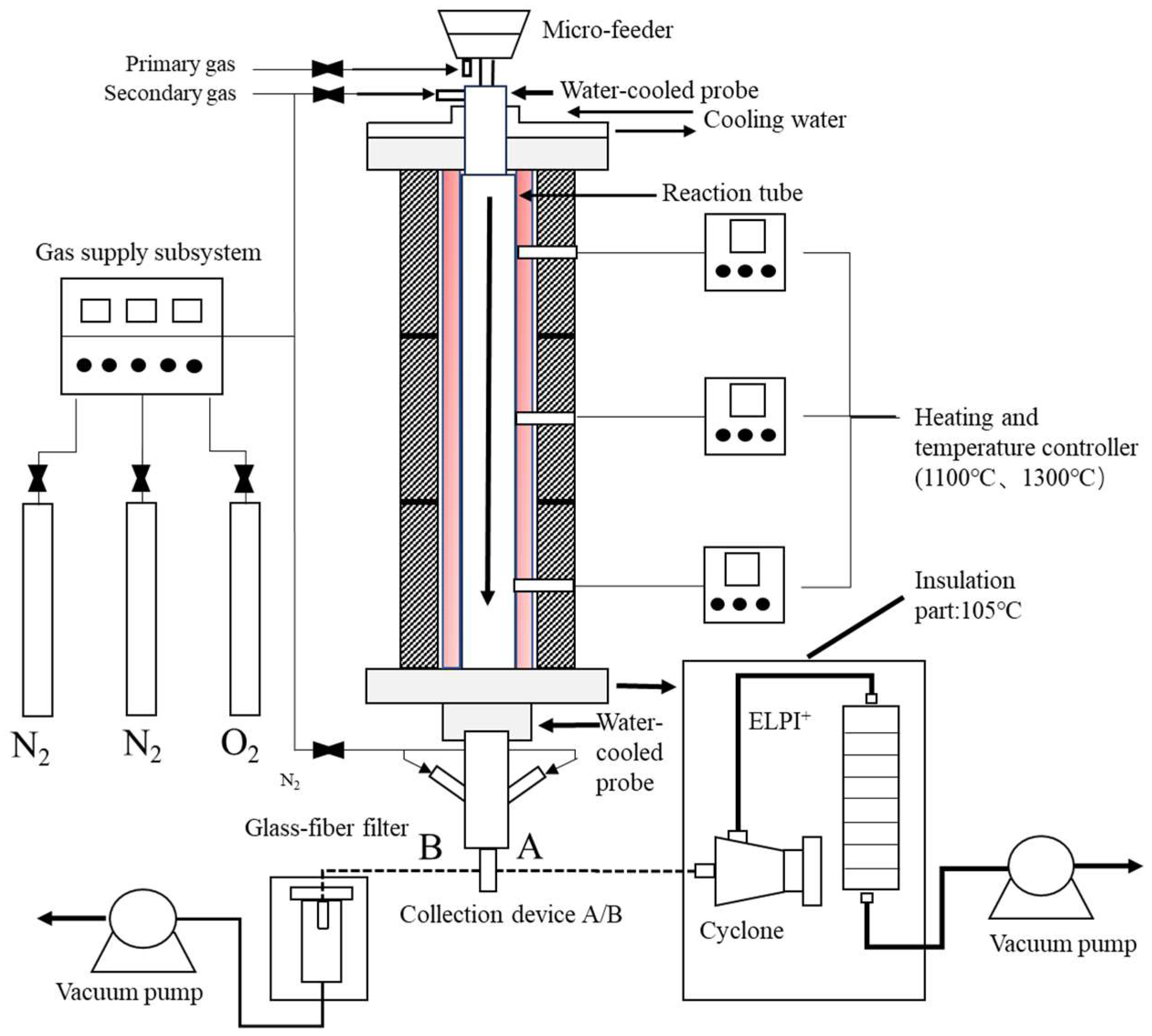
Figure 2.
PSDs of (a) WS and (b) SS and their residual ashes from the combustion at 1100 °C and 1300 °C.
Figure 2.
PSDs of (a) WS and (b) SS and their residual ashes from the combustion at 1100 °C and 1300 °C.
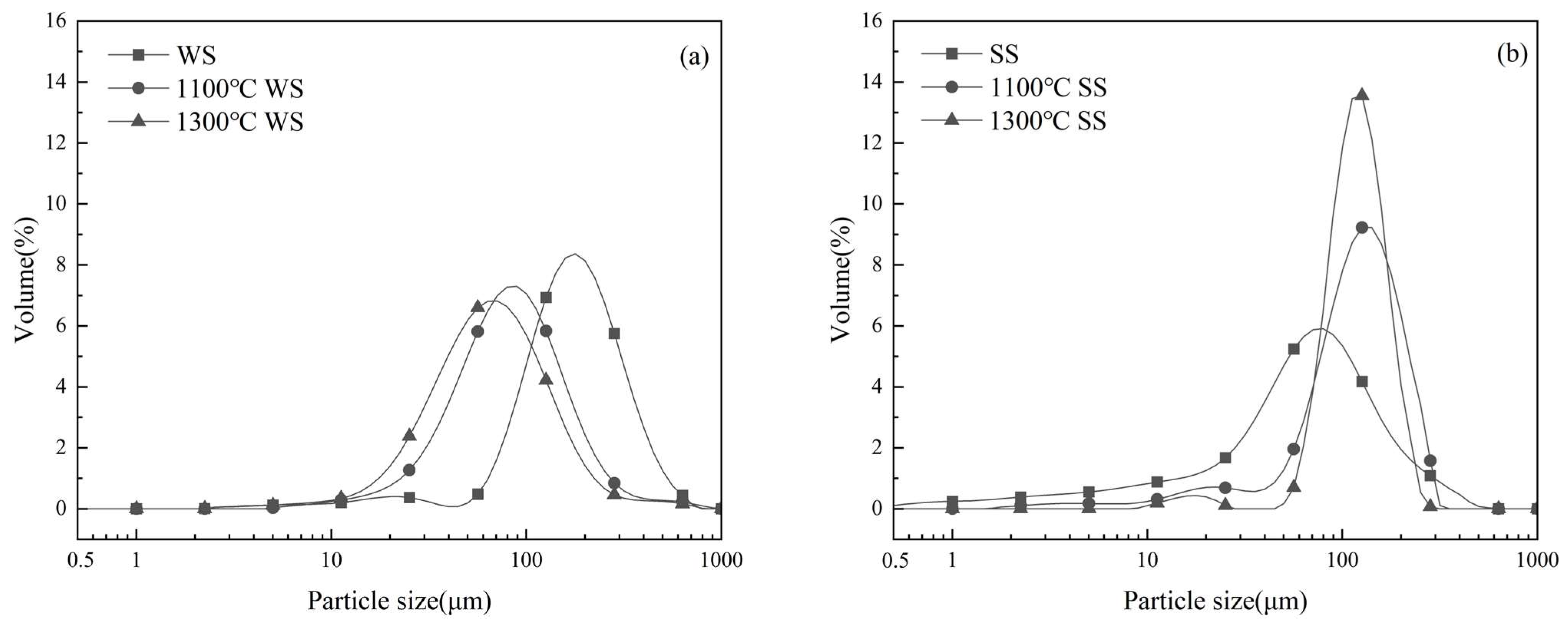
Figure 3.
SEM images (300×) of residual ash particles from the combustion of WS, SS, and their blends at (a–e) 1100 °C and (f–j) 1300 °C.
Figure 3.
SEM images (300×) of residual ash particles from the combustion of WS, SS, and their blends at (a–e) 1100 °C and (f–j) 1300 °C.


Figure 4.
Measured and additively calculated PSDs of the bulk ashes from the combustion of three blends of WS and SS at (a) 1100 °C and (b) 1300 °C.
Figure 4.
Measured and additively calculated PSDs of the bulk ashes from the combustion of three blends of WS and SS at (a) 1100 °C and (b) 1300 °C.

Figure 5.
XRD patterns of residual ashes: a—SiO2; b—AlPO4; c—KAlSi3O8; d—CaAl2Si2O8; e—KCl; f—Fe2O3; g—(Ca,Fe,Mg)2SiO4; h—CaSO4.
Figure 5.
XRD patterns of residual ashes: a—SiO2; b—AlPO4; c—KAlSi3O8; d—CaAl2Si2O8; e—KCl; f—Fe2O3; g—(Ca,Fe,Mg)2SiO4; h—CaSO4.
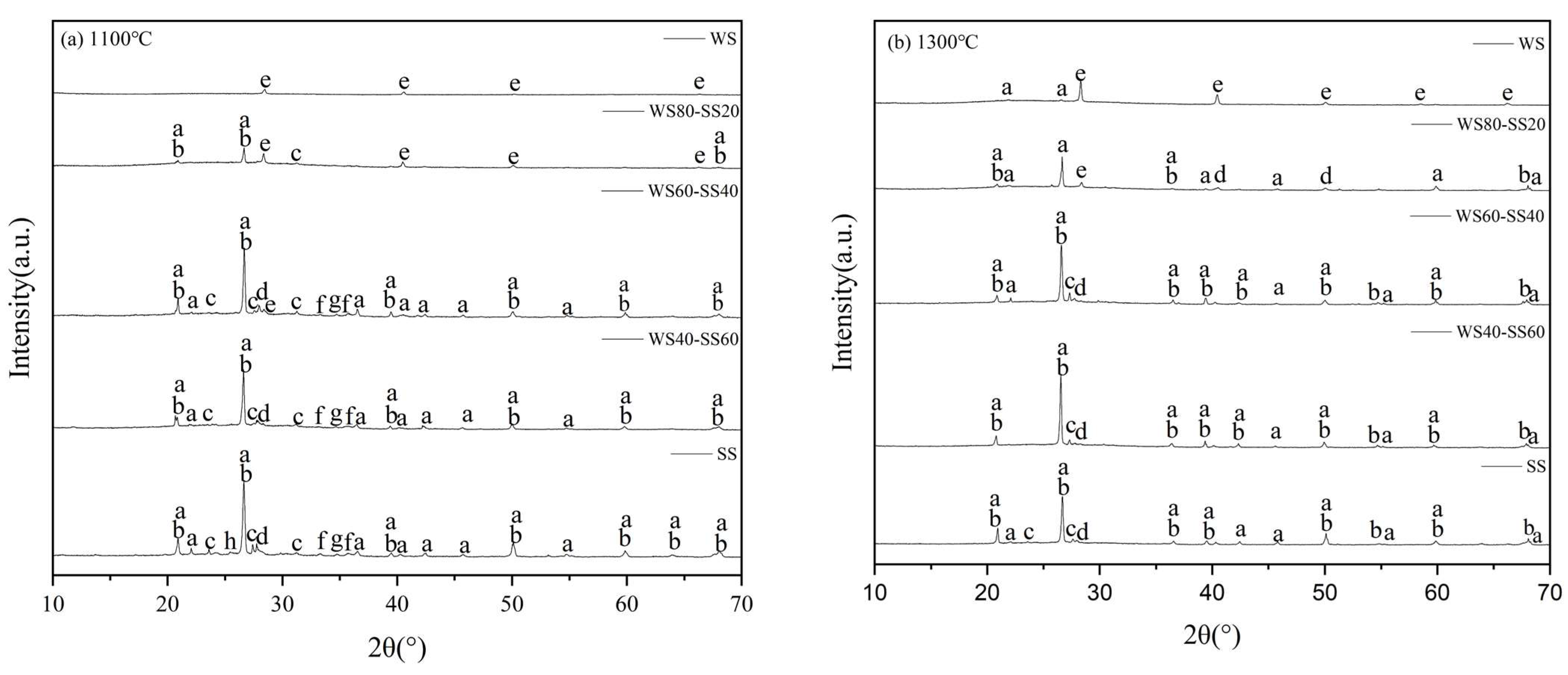
Figure 6.
Mass concentration-based PSDs of PM10 produced from WS and SS combustion at 1100 °C and 1300 °C.
Figure 6.
Mass concentration-based PSDs of PM10 produced from WS and SS combustion at 1100 °C and 1300 °C.

Figure 7.
Mass concentration-based PSDs of PM10 produced from (a) burning the three blends and parent fuels at 1300 °C and (b) burning WS80-SS20 at 1100 °C and 1300 °C.
Figure 7.
Mass concentration-based PSDs of PM10 produced from (a) burning the three blends and parent fuels at 1300 °C and (b) burning WS80-SS20 at 1100 °C and 1300 °C.

Figure 8.
Cumulative concentrations of (a) PM1 and (b) PM1–10 generated from the combustion at 1100 °C and 1300 °C, varying with the blending ratio of SS with WS.
Figure 8.
Cumulative concentrations of (a) PM1 and (b) PM1–10 generated from the combustion at 1100 °C and 1300 °C, varying with the blending ratio of SS with WS.
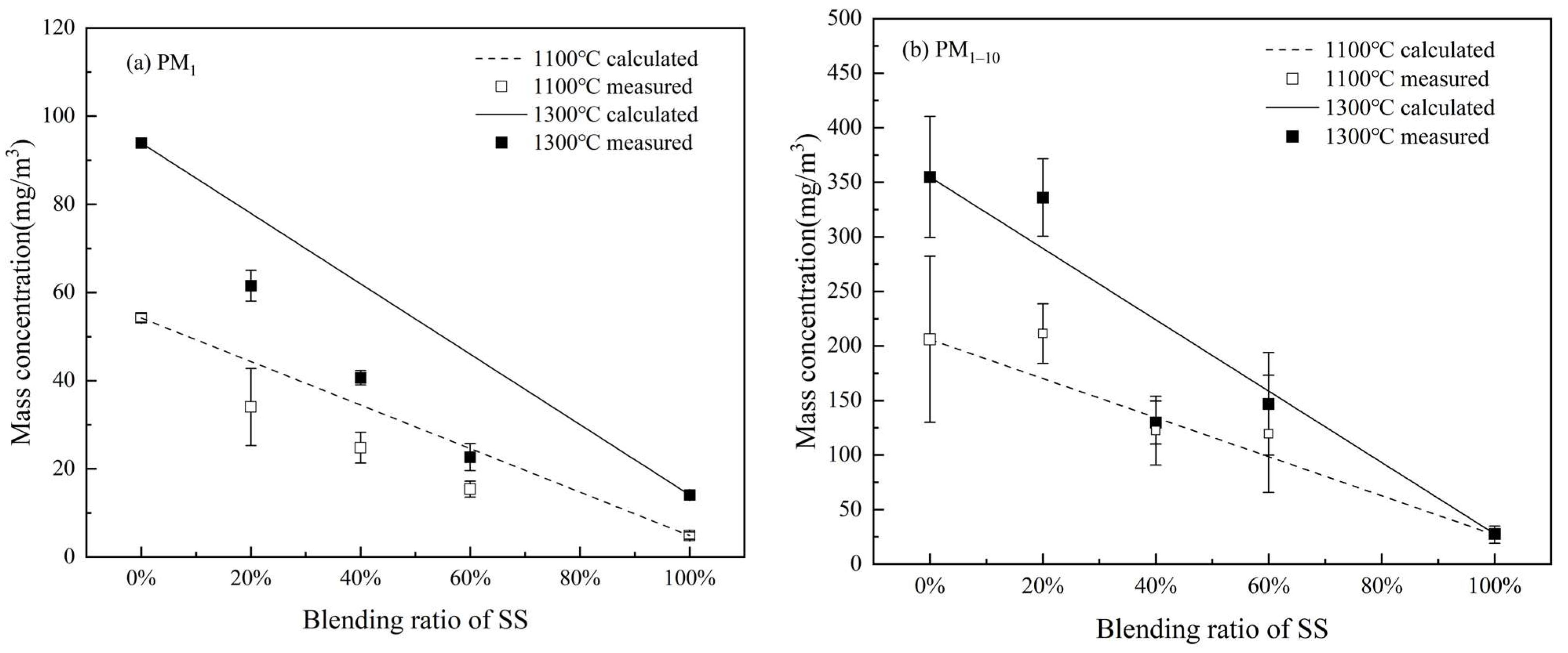
Figure 9.
Elemental compositions of PM1 and PM1–10 from the combustion of WS, SS, and their blends: (a) 1100 °C PM1, (b) 1100 °C PM1–10, (c) 1300 °C PM1, and (d) 1300 °C PM1–10.
Figure 9.
Elemental compositions of PM1 and PM1–10 from the combustion of WS, SS, and their blends: (a) 1100 °C PM1, (b) 1100 °C PM1–10, (c) 1300 °C PM1, and (d) 1300 °C PM1–10.

Figure 10.
Comparison of the experimental results with weighted calculations for K element at different temperatures in (a) PM1 and (b) PM1–10.
Figure 10.
Comparison of the experimental results with weighted calculations for K element at different temperatures in (a) PM1 and (b) PM1–10.
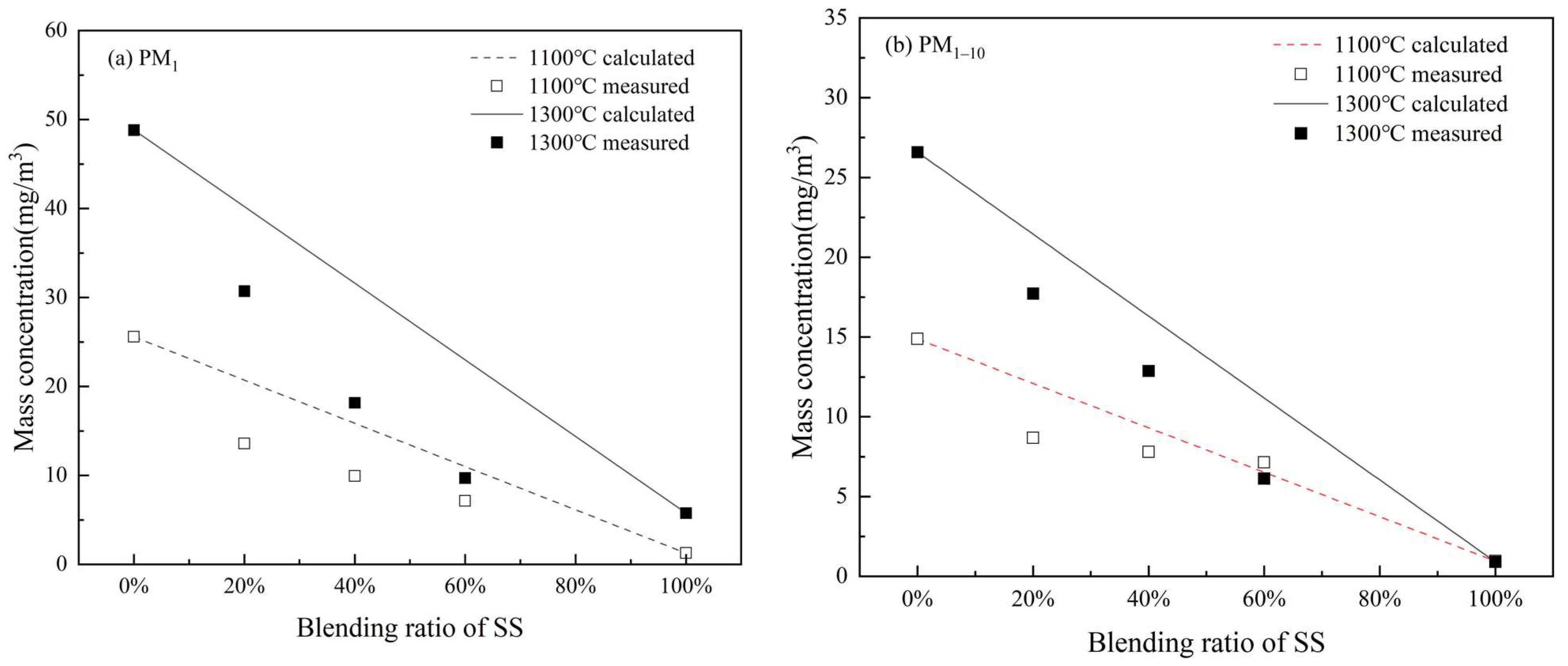
Figure 11.
Comparison of the experimental results with weighted calculations for Cl element at different temperatures in (a) PM1 and (b) PM1–10.
Figure 11.
Comparison of the experimental results with weighted calculations for Cl element at different temperatures in (a) PM1 and (b) PM1–10.

Table 1.
Proximate and ultimate analyses and heating values of the wheat straw and sewage sludge samples.
Table 1.
Proximate and ultimate analyses and heating values of the wheat straw and sewage sludge samples.
| Samples | Proximate Analysis (wt.%, Air-Dried) | Ultimate Analysis (wt.%, Air-Dried) | Lower Heating Value (MJ/kg, Air-Dried) | |||||||
|---|---|---|---|---|---|---|---|---|---|---|
| Moisture | Volatile Matter | Ash | Fixed Carbon | C | H | O | N | S | ||
| WS | 5.59 | 64.78 | 11.25 | 18.38 | 37.69 | 5.17 | 39.73 | 0.57 | <0.05 | 17.02 |
| SS | 5.25 | 36.11 | 53.73 | 4.91 | 21.18 | 3.47 | 12.64 | 3.17 | 0.56 | 8.95 |
Table 2.
Elemental compositions of the wheat straw and sewage sludge ashes (wt.%).
| Na | Mg | Al | Si | K | Ca | Fe | P | S | Cl | Others | |
|---|---|---|---|---|---|---|---|---|---|---|---|
| WS | 0.72 | 0.82 | 0.23 | 15.69 | 50.78 | 7.04 | 0.71 | 0.88 | 1.27 | 21.58 | 0.28 |
| SS | 1.21 | 2.47 | 12.17 | 31.04 | 5.24 | 14.50 | 15.29 | 11.09 | 3.20 | 1.00 | 2.79 |
Table 3.
Molar ratios of the major elements composed of PM1.
| Combustion Temperature | Blending Ratio of SS | (Na + K)/Cl | (Na + K)/2S | (Na + K)/(2S + P) | (Na + K)/(Cl + 2S) | (Na + K)/(Cl + 2S + P) |
|---|---|---|---|---|---|---|
| 1100 °C | 0% | 1.01 | 9.14 | 7.79 | 0.91 | 0.89 |
| 20% | 1.06 | 5.37 | 3.64 | 0.95 | 0.82 | |
| 40% | 1.09 | 5.27 | 4.07 | 0.90 | 0.86 | |
| 60% | 1.17 | 4.13 | 2.96 | 0.91 | 0.84 | |
| 100% | 6.09 | 1.04 | 0.69 | 0.89 | 0.62 | |
| 1300 °C | 0% | 1.12 | 38.44 | 21.1 | 1.09 | 1.06 |
| 20% | 1.18 | 8.59 | 4.26 | 1.04 | 0.93 | |
| 40% | 1.30 | 4.17 | 3.08 | 1.01 | 0.92 | |
| 60% | 1.57 | 3.23 | 1.66 | 1.05 | 0.80 | |
| 100% | 11.39 | 1.30 | 0.96 | 1.17 | 0.88 |
Disclaimer/Publisher’s Note: The statements, opinions and data contained in all publications are solely those of the individual author(s) and contributor(s) and not of MDPI and/or the editor(s). MDPI and/or the editor(s) disclaim responsibility for any injury to people or property resulting from any ideas, methods, instructions or products referred to in the content. |
© 2024 by the authors. Licensee MDPI, Basel, Switzerland. This article is an open access article distributed under the terms and conditions of the Creative Commons Attribution (CC BY) license (https://creativecommons.org/licenses/by/4.0/).
Share and Cite
MDPI and ACS Style
Shan, Y.; Zhou, H.; Sheng, C. Ash Formation and Associated Interactions during Co-Combustion of Wheat Straw and Sewage Sludge. Energies 2024, 17, 1486. https://doi.org/10.3390/en17061486
AMA Style
Shan Y, Zhou H, Sheng C. Ash Formation and Associated Interactions during Co-Combustion of Wheat Straw and Sewage Sludge. Energies. 2024; 17(6):1486. https://doi.org/10.3390/en17061486
Chicago/Turabian StyleShan, Yingnan, Hongfang Zhou, and Changdong Sheng. 2024. "Ash Formation and Associated Interactions during Co-Combustion of Wheat Straw and Sewage Sludge" Energies 17, no. 6: 1486. https://doi.org/10.3390/en17061486
Note that from the first issue of 2016, this journal uses article numbers instead of page numbers. See further details here.