Study on Proppant Transport and Placement in Shale Gas Main Fractures
Abstract
:1. Introduction
2. Liquid–Solid Two-Phase Flow Mathematical Model
2.1. Governing Equations
2.2. Constitutive Equation
2.3. Boundary Conditions
3. Experimental and Numerical Model Validation
3.1. Geometric Modeling and Meshing
3.2. Experimental Parameter Settings
3.3. Numerical Model Validation
4. Results
4.1. Effect of Displacement
4.2. Effect of Viscosity
4.3. Effect of Fracture Width
4.4. Effect of Shot Hole Location
5. Conclusions
- (1)
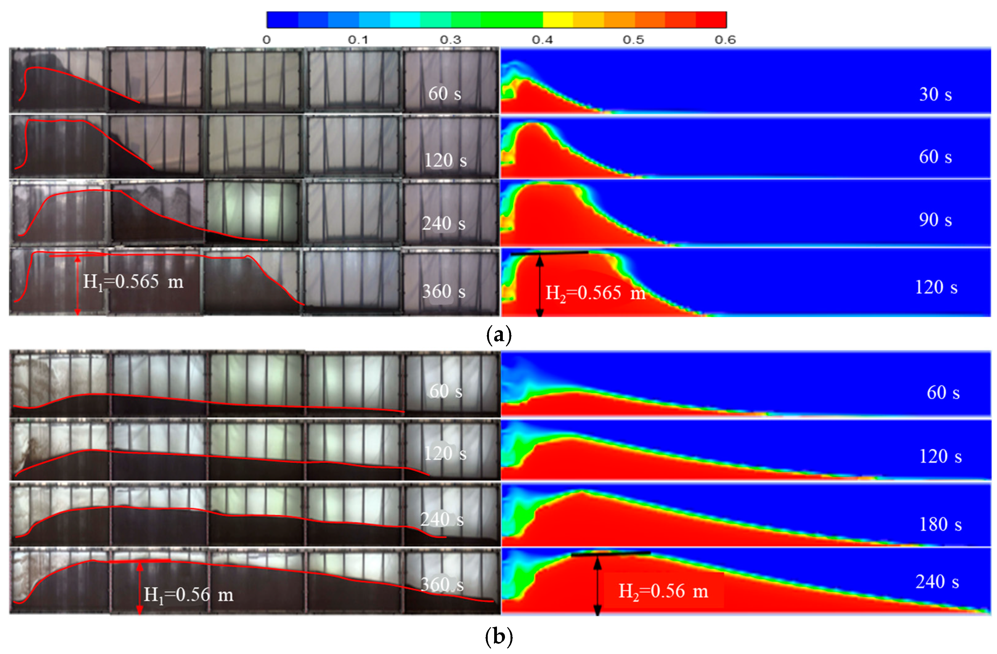
- The laboratory experiment was in good agreement with the simulation results, indicating that the Euler two-fluid method can reflect the flow of proppant in the fracture well, and the numerical model established is effective and feasible.
- (2)
- The process of proppant accumulation in the fracture can be divided into three stages. The first stage is the gravity settlement stage, which forms a small sand bank at the bottom of the fracture; The second stage is the vertical growth stage, in which the proppant accumulates in the vertical direction and the height increases. The third stage is the horizontal growth stage, when the proppant settles to the length beyond the equilibrium height.
- (3)
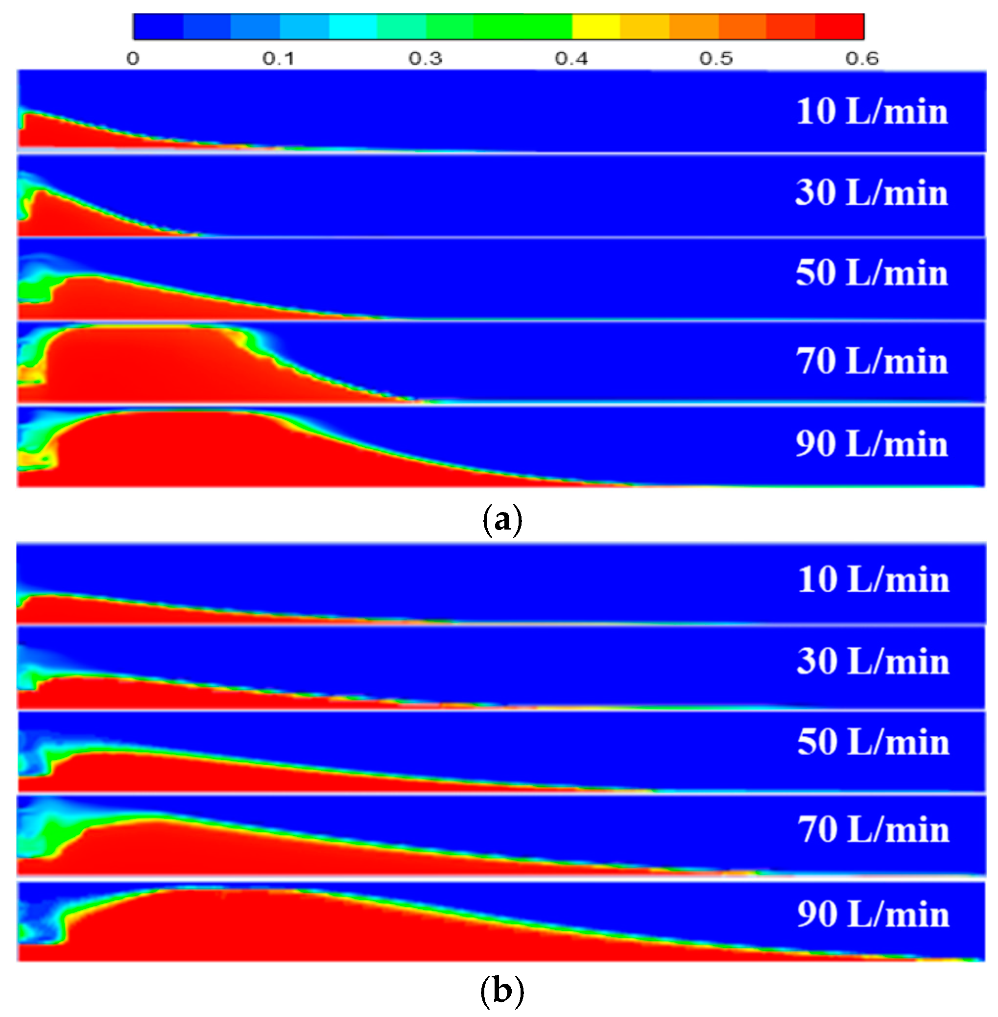
- The displacement mainly affects the proppant settlement distance, equilibrium height and equilibrium time in the early stage. The larger the displacement, the smaller the equilibrium height, the faster the proppant accumulation, and the farther the migration distance, but the larger the unfilled area at the inlet. Fracturing fluid viscosity mainly affects the settling rate and migration distance of the proppant. The greater the viscosity, the slower the settling rate of the proppant, which is more conducive to sending the proppant to the remote well zone.
- (4)
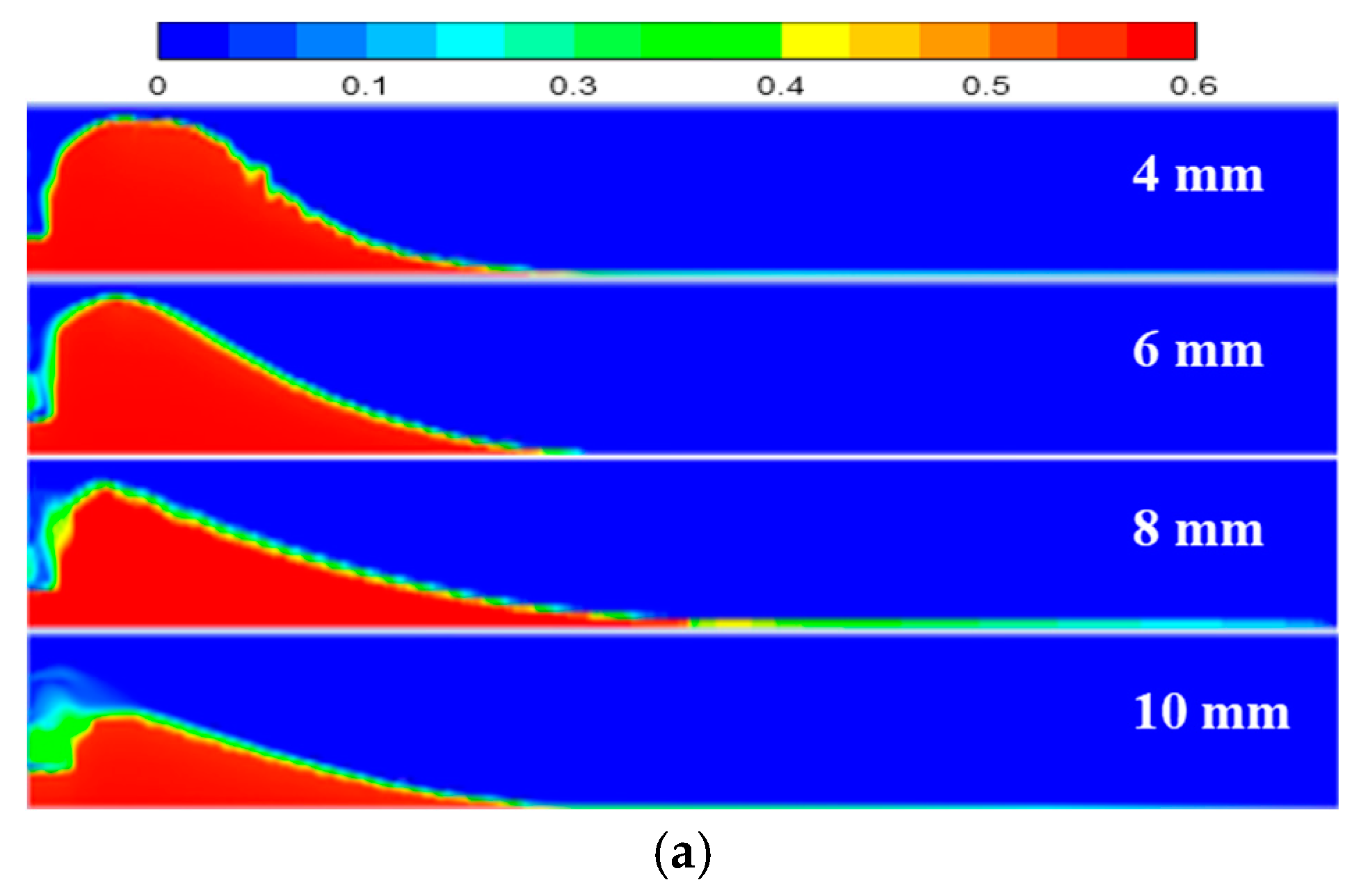
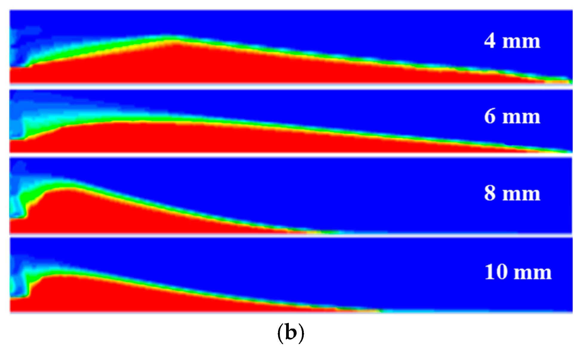
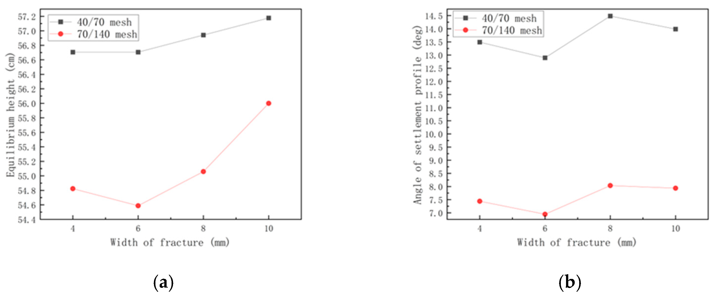
- The smaller the proppant particle size is, the easier it is for it to be carried deeper into the fracture by the fluid, the smaller the equilibrium height, and the smoother the inlet angle and settlement slope angle. The width of the fracture has little effect on proppant accumulation, but when the fracture is narrow, the proppant is affected more by the wall surface, and the upper end of the accumulation body will show pits. The injection position only affects the accumulation near the well, but has little influence on the far end of the fracture and the equilibrium height.
Author Contributions
Funding
Data Availability Statement
Conflicts of Interest
References
- Kern, L.R.; Perkins, T.K.; Wyant, R.E. The mechanics of sand movement in fracturing. J. Pet. Technol. 1959, 11, 55–57. [Google Scholar] [CrossRef]
- Fredrickson, S.E.; Broaddus, G.C. Selective placement of fluids in a fracture by controlling density and viscosity. J. Pet. Technol. 1976, 28, 597–602. [Google Scholar] [CrossRef]
- Liu, Y.; Sharma, M.M. Effect of fracture width and fluid rheology on proppant settling and retardation: An experimental study. In Proceedings of the SPE Annual Technical Conference and Exhibition, Dallas, TX, USA, 9–12 October 2005. SPE-96208-MS. [Google Scholar]
- Dayan, A.; Stracener, S.M.; Clark, P.E. Proppant transport in slick-water fracturing of shale-gas formations. In Proceedings of the SPE Annual Technical Conference and Exhibition, New Orleans, LA, USA, 4–7 October 2009. SPE-125068. [Google Scholar]
- Sahai, R.R.; Miskimins, J.L.; Olson, K.E. Laboratory results of proppant transport in complex fracture systems. In Proceedings of the SPE Hydraulic Fracturing Technology Conference, The Woodlands, TX, USA, 4–6 February 2014. SPE-168579-MS. [Google Scholar]
- Zhang, K.; Zhang, T.; Wu, S.; Li, N.; He, S. Simulation of proppant transport in fracture with different combinations of particle size. Reserv. Eval. Dev. 2019, 9, 72–77. [Google Scholar]
- Zhang, L.; Qu, Z.; Lyu, M. Support effect of different particle proppant combinations on complex fractures. Fault-Block Oil Gas Field 2021, 28, 278–283. [Google Scholar]
- Gao, J.; Hu, L.; Wang, G.; Yang, W. Experimental Study on the Effect of Fracturing Sand Ratio on Proppant Placement in Unconventional Reservoirs. Drill. Prod. Technol. 2022, 45, 90–95. [Google Scholar]
- Tang, T.; Guo, J.; Weng, D.; Shi, Y.; Xu, K.; Li, Y. Experimental study of proppant transport in flat fracture based on PIV/PTV. Pet. Drill. Tech. 2023, 51, 121–129. [Google Scholar]
- Tsuji, Y.; Kawaguchi, T.; Tanaka, T. Discrete particle simulation of two-dimensional fluidized bed. Powder Technol. 1993, 77, 79–87. [Google Scholar] [CrossRef]
- Zhang, T.; Li, C.; Shi, Y.; Mu, K.; Wu, C.; Guo, J.; Lu, C. Numerical simulation of proppant directly entering complex fractures in shale gas. J. Nat. Gas Sci. Eng. 2022, 107, 104792. [Google Scholar] [CrossRef]
- Zhang, T.; Guo, J.; Liu, W. CFD simulation of proppant transport settlement behavior in clear water fracturing. J. Southwest Pet. Univ. (Nat. Sci. Ed.) 2014, 36, 74–82. [Google Scholar]
- Zhou, D.; Zhang, Z.; Hui, F.; Shi, Y.; Zhao, C.; Zhou, Y. Experimental and numerical simulation of proppant transport in main fracture of slick water fracturing. Oil Drill. Prod. Technol. 2017, 39, 499–508. [Google Scholar]
- Kong, X.; McAndrew, J. A computational fluid dynamics study of proppant placement in hydraulic fracture networks. In Proceedings of the SPE Canada Unconventional Resources Conference, Calgary, AB, Canada, 15–16 February 2017. D011S002R004. [Google Scholar]
- Hao, L. CFD Numerical simulation of proppant settlement and migration in complex fractures. Petrochem. Appl. 2020, 39, 30–32,48. [Google Scholar]
- Srivastava, A.; Sundaresan, S. Analysis of a frictionalkinetic model for gas-particle flow. Powder Technol. 2003, 129, 72–78. [Google Scholar] [CrossRef]
- Gidaspow, D.; Bezburuah, R.; Ding, J. Hydrodynamics of Circulating Fluidized Beds, Kinetic Theory Approach; Department of Chemical Engineering: Chicago, IL, USA, 1991; pp. 75–82. [Google Scholar]
- Benyahia, S.; Syamlal, M.; O’Brien, T.J. Evaluation of boundary conditions used to model dilute, turbulent gas/solids flows in a pipe. Powder Technol. 2005, 156, 62–72. [Google Scholar] [CrossRef]






| Site Displacement (m3/min) | Height of Artificial Crack (m) | Height of Flatbed Unit (m) | Number of Perforation Clusters | Experimental Displacement (L/min) |
|---|---|---|---|---|
| 12 | 30 | 0.6 | 12 | 10 |
| 18 | 10 | 0.6 | 6 | 90 |
| Proppant Size | Displacement (L/min) | Fluid Viscosity (mPa∙s) | Width of Crack (mm) | Position of Injection |
|---|---|---|---|---|
| 40/70, 70/140 | 70 | 2.5 | 10 | Three-hole injection |
| Displacement (L/min) | Proppant Size (mesh) | Fluid Viscosity (mPa·s) | Width of Fracture (mm) |
|---|---|---|---|
| 50 | 70/140 | 2.5 | 10 |
Disclaimer/Publisher’s Note: The statements, opinions and data contained in all publications are solely those of the individual author(s) and contributor(s) and not of MDPI and/or the editor(s). MDPI and/or the editor(s) disclaim responsibility for any injury to people or property resulting from any ideas, methods, instructions or products referred to in the content. |
© 2024 by the authors. Licensee MDPI, Basel, Switzerland. This article is an open access article distributed under the terms and conditions of the Creative Commons Attribution (CC BY) license (https://creativecommons.org/licenses/by/4.0/).
Share and Cite
Liang, T.; Xiu, N.; Fu, H.; Jian, Y.; Zhang, T.; Du, X.; Tu, Z. Study on Proppant Transport and Placement in Shale Gas Main Fractures. Energies 2024, 17, 1537. https://doi.org/10.3390/en17071537
Liang T, Xiu N, Fu H, Jian Y, Zhang T, Du X, Tu Z. Study on Proppant Transport and Placement in Shale Gas Main Fractures. Energies. 2024; 17(7):1537. https://doi.org/10.3390/en17071537
Chicago/Turabian StyleLiang, Tiancheng, Nailing Xiu, Haifeng Fu, Yinlin Jian, Tao Zhang, Xingyang Du, and Zhicheng Tu. 2024. "Study on Proppant Transport and Placement in Shale Gas Main Fractures" Energies 17, no. 7: 1537. https://doi.org/10.3390/en17071537
APA StyleLiang, T., Xiu, N., Fu, H., Jian, Y., Zhang, T., Du, X., & Tu, Z. (2024). Study on Proppant Transport and Placement in Shale Gas Main Fractures. Energies, 17(7), 1537. https://doi.org/10.3390/en17071537


