
Principles for the Design of a Biomass-Fueled Internal Combustion Engine

1
Department of Energy and Fuels, E.T.S. Ingenieros de Minas y Energía, Universidad Politécnica de Madrid, Ríos Rosas 21, 28003 Madrid, Spain
2
Research and PhD Sub-Directorate, Escuela Politécnica Superior del Ejército, Joaquín Costa 6, 28006 Madrid, Spain
3
Department of Weapon Systems Industrial Technologies, Research and PhD Sub-Directorate, Escuela Politécnica Superior del Ejército, Joaquín Costa 6, 28006 Madrid, Spain
4
Escuela Politécnica Superior del Ejército, Joaquín Costa 6, 28006 Madrid, Spain
*
Author to whom correspondence should be addressed.
Energies 2024, 17(7), 1700; https://doi.org/10.3390/en17071700
Submission received: 29 February 2024
/
Revised: 20 March 2024
/
Accepted: 29 March 2024
/
Published: 2 April 2024
(This article belongs to the Special Issue Internal Combustion Engine: Research and Application—2nd Edition)
Abstract
:Biomass-fueled engines are a promising way to reduce the consumption of and dependence on fossil fuels. To create a working prototype, a detailed study of the thermodynamic cycle was developed. The dead volume was revealed to be the most limiting parameter for the engine efficiency. The cycle efficiency is reduced from 51.8% to 30.5% for the given example. The engine needs to be properly designed to minimize energy losses. In addition, the optimal compression ratio of the cycle is very low (about 3.5), losing energy in the exhaust gases and contributing to an inefficient engine. However, using a turbocharger can improve the cycle efficiency, combining the basic cycle with a Brayton cycle. Moreover, a two-stroke engine design is recommended for biomass-fueled engines. It allows minimization of the dead volume, is less sensitive to dirt, and avoids gas exchange with the combustion chamber during scavenging. Finally, the combustion chamber of the initial prototype was redesigned, based on the aforementioned improvements and allowing the successful start-up of the engine. This work demonstrates that biomass is a viable alternative to fossil fuels in applications where internal combustion engines are required.
1. Introduction
Today our society depends on fossil fuels. Fundamental activities, such as agriculture, transportation, and mining, are powered by internal combustion engines that use petroleum-based fuels. The replacement of these fuels is a priority: (1) as the latest Intergovernmental Panel on Climate Change (IPCC) report presages, the emission of greenhouse gases is causing climate change that threatens future society [1]; (2) the location of crude oil reserves is a source of continuous conflicts [2]; and (3) petroleum is a finite resource that, at current consumption rates, can be depleted in a few decades [3].
Numerous studies have addressed this issue. One of the most promising methods is the development of alternative fuels [4,5,6,7,8,9,10,11,12,13,14,15,16,17,18,19,20,21], which are expected to replace fossil fuels in the near future. In this method, the required energy is stored in fuel tanks. The stored energy can be replenished quickly by refueling the machine. In contrast, electric machines need heavy and bulky batteries because of the low energy density of current batteries [22]. In addition, the electric power supply needed to recharge the batteries may be restricted to a few hours [23] and require a significant amount of time. Consequently, electrically powered machines are currently restricted to specific applications [24,25].
But the development of a suitable alternative fuel has proved to be difficult. To date, most of the research has been only partially successful [4,5,6,7,8,9,10,11,12,13,14,15,16,17,18,19,20,21]. Additionally, the fuels obtained are sometimes of very poor quality and problematic in engines [18]. Biomass could be a suitable alternative to petroleum-based fuels. As an alternative fuel, biomass pellets have two main advantages: (1) they are available in large quantities so they can replace a large amount of the petroleum fuels that are currently used. Biomass is a poorly used power source [26,27] and has great potential. Specifically, the potential production of biomass in Spain [28] equals the amount of diesel fuel consumed [29], both measured in terms of power. In addition, (2) biomass pellets can be safely stored in the machine. This contrasts with other proposed alternative fuels such as hydrogen [30,31,32].
However, the use of biomass as a fuel is currently restricted to heating applications. Biomass boilers are very successful [33], but biomass burns in the solid state and cannot be used in diesel or spark-ignition engines that use liquid or gas fuels. There have been attempts to build solid fuel engines (Table 1, Figure 1) which could be fueled by biomass, but they have been unsuccessful [34,35,36,37,38].
Nevertheless, these engines would allow the acquisition of energy from agricultural and forestry by-products, which can be found in practically every part of the world. Climate change, conflicts, and the crude-oil price increase make the development of these engines very attractive.
However, because biomass resources are limited, engines must be efficient for practical use. The optimal compression ratio for a biomass-fueled engine is extremely low for current standards [39,40]. Modern engines are designed to have a compression ratio higher than 10, because higher compression ratios improve engine efficiency. As the compression of an Otto cycle is adiabatic, gases are heated when compressed. Thus, a higher compression ratio allows the compressed gases to become warmer before combustion. This raises mean combustion (heat absorption) temperature and improves the Carnot factor and cycle efficiency. The low optimal compression ratio of the cycle of a biomass-fueled engine means that the efficiency will be much lower than equivalent diesel engines. This could limit the future applications of biomass-fueled engines.
Fortunately, there is a suitable solution for that problem: to fit a turbocharger to the engine. This way, intake air can be compressed (and, thus, adiabatically heated) before entering the cylinder. The mean combustion temperature is increased, thereby improving cycle efficiency. Furthermore, as in diesel engines, the fuel is not previously mixed with the intake air. Therefore, there is no detonation risk, and the intake air can be heavily compressed.
But more important than compressing the intake air is to fully expand the exhaust gases, taking advantage of their energy. The lower the compression ratio, the lower the work performed during expansion. With a low compression ratio, most of the available energy is released by the exhaust gases. When, at the end of the expansion stroke, the exhaust port is uncovered, some pressure remains in the cylinder. Gases are released almost instantaneously and accelerated through the exhaust duct. Thus, the pressure energy is mainly converted into kinetic energy. That energy is wasted in a non-turbocharged engine. But in a turbocharged engine, part of that energy is taken by the turbine to compress the intake air.
However, the energy that can be obtained from exhaust gases is greater than the energy needed to compress the intake air. This is because the exhaust temperature is higher. Even in turbocharged engines, some energy from exhaust gases is wasted. To avoid this, the turbocompound technology was developed. Turbocompound engines are fitted with a second turbine that takes the remnant energy from the exhaust gases and transfers it to the crankshaft. Most of the current turbocompound engines are diesel engines. Diesel engines have a high compression ratio. Therefore, a lot of work is performed during the expansion stroke, and very little energy is released in the exhaust gases. As a result, in diesel engines, turbocompound technology slightly improves engine efficiency [41]. In contrast, due to their low compression ratio, turbocompound technology can significantly improve the efficiency of biomass-fueled engines.
This article has the following objectives: (1) to define the concept of ‘dead volume’ and quantify its impact on engine performance; (2) find out the optimal compression ratio value for biomass-fueled engines; (3) establish other principles for engine design; (4) quantify how much the turbocompound technology can improve engine efficiency; (5) estimate if the biomass resources are abundant enough to replace currently used petroleum-based fuels; and (6) make a design proposal for a combustion chamber suitable for biomass-fueled internal combustion engines.
2. Methodology
2.1. First Prototype
The aim of this research is to demonstrate the feasibility of using biomass as an alternative to fossil fuels for use in internal combustion engines. Thus, an engine prototype was manufactured from a diesel engine. Standard biomass pellets [42] were selected as fuel because of their widespread availability. The combustion chamber and fuel feeder dimensions must be significantly greater than the biomass pellet length. Otherwise, the fuel feeder may become clogged, preventing the fuel from reaching the bottom of the combustion chamber and thus stopping the engine. Consequently, the largest displacement single-cylinder engine (Figure 2a) was selected: the Lombardini LDA 820 (Lombardini Srl, Reggio Emilia, Italy). Its basic technical specifications are shown in Table 2.
The engine runs on a four-stroke cycle; therefore, gas exchange is carried out through poppet valves located at the engine head. To save funding, the manufacture of a new four-stroke engine head was discarded. Instead, the cylinder was modified to create a two-stroke engine; thus, the gas exchange ports were opened in the cylinder wall. A vacuum cleaner motor was used for performing the cylinder scavenging (Figure 2b). The engine was relocated to achieve a nearly horizontal cylinder engine. Thus, a new oil pan was fitted and the oil suction pipe was extended (Figure 3).
With a horizontal cylinder, the exhaust port can point downward to evacuate ash and other particles from the cylinder as quickly as possible. Furthermore, the piston was modified by removing the combustion chamber and placing an aluminum cap. Thus, a flat-head piston was achieved (Figure 2b). Additionally, minor changes were made to the engine. For example, the oil slip ring was removed. Subsequently, a simple, disk-shaped combustion chamber was attached as a cylinder head chamber (Figure 4a). A diesel engine glow plug (Figure 4a) and an air injector (Figure 5) were fitted for cold starting. A large ceramic grille was fitted to keep the fuel in the combustion chamber (Figure 4b). Finally, a basic fuel feeder was attached to the top of it (Figure 5) and a drain plug was fitted to the bottom.
But the first prototype did not start. As the available grille was quite thick, it was suspected that some of the air remained in the grille holes after the compression stage instead of entering the combustion chamber. Fortunately, this fact can be simulated in the thermodynamic cycle [39]. Thus, the concept of ’dead volume’ was developed (Figure 6).
Figure 6 shows the process followed to achieve a functional prototype. After the dead volume impact was established, the combustion chamber was redesigned to minimize it.
2.2. The Dead Volume
2.2.1. Dead Volume Definition
The thermodynamic cycle of a biomass-fueled engine [39] was defined as being carried out in an ideal engine. In this case, all the gases present in the cylinder fully entered the combustion chamber at the end of the compression stroke. However, a gap between the cylinder head and the piston is necessary when the piston reaches the top dead center (TDC). Otherwise, the piston would collide with it, damaging the engine. In other engines, this volume is part of the combustion chamber. Therefore, the air that remains there always takes part in the combustion. However, in a biomass-fueled engine, the grille effectively separates the volume of the cylinder and the combustion chamber. Consequently, the air which remains in the cylinder when the piston reaches the TDC cannot take part in the combustion. The fuel is kept in the combustion chamber, and only the air that crosses the grille reacts with it. As a result, the gap between the piston and the cylinder head makes a ‘dead volume’. The air contained within this volume never participates in the combustion process.
The dead volume of the cylinder is very small. The minimum distance between the piston head and the grille can be less than one millimeter. In contrast, piston stroke can be larger than a hundred millimeters. However, the compressed air remains in the holes of the grille too. Moreover, during engine operation, there is little time to complete combustion. In current engines, combustion occurs when the fuel is in the gas state and mixed with the air (spark-ignition engines) of finely sprayed (diesel engines). In both cases, combustion can progress very quickly and become complete in a short period of time. However, in biomass-fueled engines, combustion is much slower. If the engine spins quickly, combustion cannot be completed. Consequently, part of the air that enters the combustion chamber is unable to react with the fuel before the gases exit the combustion chamber during the expansion stroke. This effect contributes to an increase in the dead volume. The higher the engine speed, the shorter the time to complete combustion and the higher the dead volume. Hence, there are three contributors to the dead volume: (1) the gap between the grille and the piston head at the TDC, (2) the volume of the holes of the grille, and (3) the air that is unable to react with the fuel.
The dead volume of the cylinder and the grille can be calculated geometrically, but the amount of air that is unable to react with the fuel depends on the engine speed, and it must be estimated. The dead volume causes the compression stage to become incomplete. The gases are expanded before they fully enter the combustion chamber. Thus, a new parameter () must be defined. indicates the maximum compression progress. is defined by the following equation:
where is the calculated dead volume and is the volume of the cylinder at the beginning of the compression stroke, just when the exhaust port is fully covered.
2.2.2. Calculation Method
The work performed during compression stroke () can be calculated by the developed methods [39]. But the dead volume effect makes the cycle calculation more difficult. If , at the beginning of the expansion stroke, both in the cylinder and in the combustion chamber there are gases with different temperatures. This fact would make the expansion calculation as complex as compression calculation. To avoid this, an equivalent temperature () is defined:
Then, the gases both in the cylinder and in the combustion chamber are assumed to be at the same temperature (). This way, expansion can be calculated as a simple adiabatic expansion. Thus, the work performed during the expansion stroke is:
2.3. Improving Biomass-Fueled Engine Efficiency
As shown in the Introduction, the efficiency of biomass-fueled engines can be improved by fitting them with a turbocharger and using turbocompound technology to take advantage of the energy of the exhaust gases. In short, the biomass-fueled engine cycle must be combined with a Brayton cycle. For the cycle calculations, both cycles must be solved separately. It should be noted that the Brayton cycle is carried out with moles. This is because the gases which remain in the combustion chamber during cylinder scavenging do not perform the Brayton cycle. Firstly, the intake air is compressed adiabatically from the ambient pressure () and temperature ().
where is the pressure ratio of the compressor. and are the initial conditions of the cylinder’s cycle, as defined in [39]. The work consumed by the compressor is:
After that, the engine cycle has to be solved using methods previously defined [39]. Initial conditions will be , , , , and . Cycle solving allows determination of and . These conditions are those that exist in the cylinder when the exhaust port is uncovered. Next, the exhaust gases are considered to be fully expanded by the turbine. The turbine outflow temperature () is:
And the work performed by the turbine is:
The total work is , plus the work performed by the cycle in the cylinder (). Combined cycle efficiency is obtained by dividing the total work by the heat absorbed ().
2.4. Proposal for Combustion Chamber Design
The main differences between the proposed engine and other internal combustion engines are the layout of the combustion chamber and the presence of a separator grille. Correct combustion is essential for the proper functioning of the engine. Therefore, the combustion chamber must be adapted to burn a fuel with completely different physical characteristics than usual fuels. In the proposed engine, combustion takes place in a chamber attached to the cylinder but separated from it by the grille.
The design of the combustion chamber must meet several requirements. Some of the most important are the following:
- The shape must be similar to a sphere to minimize heat loss.
- One of the walls of the chamber must be the grille.
- Dead volume must be reduced as much as possible.
- The chamber must allow the free movement of the fuel. Therefore, the separation between the walls must be significantly greater than the granulometry of the fuel.
- The filling of the chamber is carried out by gravity. Thus, the fuel feeder must be attached to the upper part of the chamber.
- At the bottom of the chamber, there must be an emptying system to evacuate the ash produced and enable the chamber to be emptied, if necessary.
- It must allow the heating system components to be accommodated for cold starting.
A combustion chamber was designed based on these requirements.
3. Results
3.1. Dead Volume Impact on the Thermodinamic Cycle
As shown in a previous publication [39], the compressed air enters the combustion chamber mainly at the end of compression. Even if the compression is not completed by a small percentage, there is a significant impact on the cycle efficiency. For example, Figure 7 and Table 3 show the impact of on a typical cycle:
As shown in Figure 5, the work obtained is less than half, and the cycle efficiency is greatly reduced. This is because (with the initial conditions shown in Figure 5) when , 21.2% of the compressed air is unable to pass through the grille and enter the combustion chamber. Therefore, the absorbed heat () and the obtained work () are lower. In addition, the mean temperature of combustion is reduced, thus the Carnot factor is lower and, consequently, the cycle efficiency () is also lower (Table 3).
In addition, Figure 8 shows , , and as functions of for different values of .
Figure 8 shows that , , and are reduced dramatically with a small decrease in for all values of . But the most interesting fact is that the lines intersect at a certain value of . Whereas high values of improve when is close to 1, lower values of improve when is less than 0.986. The same occurs for q and . Thus, it is interesting to plot as a function of and for different values of (Figure 9).
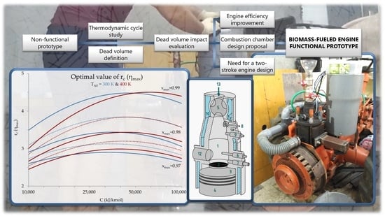
As Figure 9 shows, for (a typical value for an engine) maximum cycle efficiency occurs when . In addition, higher values of lead to poor cycle efficiency except when , a situation which never occurs. Thus, it is more appropriate to plot a graph like Figure 8, which shows the optimum value of for each value of .
The representative value of depends on the quality of the fuel burned and the heat loss of the engine. But, to describe the cycle of a partially loaded engine, a lower value of must be selected. When an engine is partially loaded, or simply idling, the blower pressure is not enough to perform a total scavenging of the cylinder gases. The cylinder gases are only partially replaced. Thus, there is less oxygen in the compressed gases and less heat is released during combustion. Furthermore, because the cylinder gases are hotter than the intake air, the temperature of the mixed gases in the cylinder prior to compression is higher. Consequently, when the engine is partially loaded, is lower and higher. For this reason, graphs for and are plotted in Figure 10.
Therefore, it is interesting to study the optimal value of over a wide range of , from very low values to the highest possible value. In addition, higher values than room temperature must be considered for low values. The optimal value of depends on , , and ; but it is independent of . Consequently, does not appear in Figure 10.
3.2. Optimal Compression Ratio of the Engine
The cycle efficiency depends on the initial conditions (,, , and ) and the value of xmax. However, the initial pressure () is similar (for a non-supercharged engine) to atmospheric pressure (), the initial temperature () depends on room temperature (), and the calorific value () of fuel depends on the available fuel and the engine heat loss. However, these three initial conditions cannot be controlled. Thus, the interesting initial condition is the compression ratio (), which can be effectively selected during the engine design.
The optimal compression ratio of the engine can be estimated using the chart in Figure 10. First, the value of must be calculated geometrically by summing the cylinder and grille dead volumes. An additional value can be added to estimate the dead volume of air that enters the combustion chamber but is unable to react with the fuel. Subsequently, the value of can be calculated by using Equation (1). This allows for the selection of the right curves in Figure 10.
Subsequently, the value of , representative of full load conditions, must be selected. The calculated value of for cellulose is 94,500 kJ/kmol; however, as the engines have large heat loses, the actual value of is estimated to be lower. For example, a value of 50,000 kJ/kmol is used. Lower values of must be selected to calculate the optimal value of when the engine is partially loaded. Nevertheless, partial-load situations can be largely ignored. The engine efficiency is less important when partially loaded. The compression ratio should be optimized under full-load conditions.
For a value of of 50,000 kJ/kmol, the optimal value of in an engine with is 3.8 both for high and low intake air temperatures. In contrast, if the same engine runs faster, the dead volume will be greater because oxygen has less time to react with the fuel. Consequently, decreases, for example, to 0.975. In this case, the optimal value of is 3.1 when , but rises to 3.2 if the engine is turbocharged and is much higher than room temperature. If the intake air is previously compressed, it enters the cylinder at a higher temperature. Initial temperature increases if the engine is also partially loaded. But, in the case of a fully loaded turbocharged engine, the cylinder gases are totally replaced during scavenging, and the value of remains independent of the value of the intake temperature.
However, a single value for must be selected. The compression ratio of the engine is a fixed value that cannot be modified based on the working conditions. Consequently, different full-load working conditions must be investigated to determine the optimal value for . Furthermore, the combustion chamber is always partially filled with the fuel. Thus, the actual value for depends on the filling degree of the chamber. This must be considered when designing the combustion chamber.
3.3. Engine Efficiency Improvement
To demonstrate the extent to which the efficiency of biomass-fueled engines can be improved, several examples are presented. Table 4 shows the differences among a plain cycle, a cycle that takes advantage of the exhaust energy, a turbocompound cycle, and a turbocompound cycle with an intercooler (in which compressed gases are cooled and the intake temperature is lower).
It is important to highlight that the Bryton cycle runs only with , the gases scavenged in the cylinder. Thus, both compressor and turbine work must be multiplied by . The cases presented in Table 4 are only examples of how cycle efficiency can be improved with the available technology. Different combined efficiency values can be obtained by modifying the values of the initial conditions (the first six rows of Table 4). Table 4 shows that intake air cooling lowers the cycle efficiency. Thus, at this point of the research, it can be said that intercoolers will make no sense in biomass-fueled engines.
However, certain limitations are expected when implementing turbocompound technology in biomass-fueled engines. First, the lower compression ratio makes exhaust gases hotter than in current engines. Consequently, the turbine will endure higher flow temperatures and more expensive materials will be required for the turbine-manufacturing process. Furthermore, the exhaust flow is expected to drag ash and burning fuel particles (Figure 11). Therefore, a filter must be fitted to the exhaust flow prior to turbine intake.
3.4. Real Engine Efficiency Estimation
It is known that the actual engine efficiency is much lower than the theoretical cycle efficiency. For example, Hatz 1D90 [43], a simple single-cylinder diesel engine, runs on an Otto cycle with the following values: ambient pressure, 100 kPa; ambient temperature, 297 K (25 °C); compression ratio, 21.5; and specific heat of the fuel, 94,500 kJ/kmol. By solving the cycle, the efficiency of the theoretical Otto cycle performed by the engine is 70%. In contrast, Hatz declares that the 1D90 engine has a specific fuel consumption of 231 g/kW·h [43]. Considering a diesel fuel lower heating value (LHV) of 11.9 kW·h/g [44], the actual engine efficiency is 36%. Thus, the actual efficiency of the engine is approximately half of the theoretical cycle efficiency.
According to Table 4, the cycle efficiency of a biomass-fueled engine will reach 70% in the best cases. Thus, the actual efficiency of these engines can be as high as 35%. In comparison, a fully developed 13-L diesel engine [45] has a specific fuel consumption of 190 g/kW·h under optimal conditions. Considering a diesel fuel LHV of 11.9 kW·h/g [44], the engine efficiency is 44%. This means that fully developed biomass-fueled engines will be less efficient than modern diesel engines. A fully developed biomass-fueled engine will use 25% more energy than a similar diesel engine to perform the same work.
This result is important because biomass resources are limited [28]. Knowing the efficiency of both types of engines, it is possible to estimate the biomass fuel demand for a particular application. In the case of Spain, the diesel fuel demand in 2019 (before the COVID-19 pandemic and the Ukrainian war) was 2.77 × 10¹⁰ kg/year [29], which is roughly half of the total petroleum-based fuel consumption. Considering a diesel fuel LHV of 43,000 J/g [44], the amount of energy used in diesel engines in 2019 was 1.2 × 10¹⁸ J/year. If all diesel engines were replaced by biomass engines, the biomass energy demand would be 25% larger, or approximately 1.5 × 10¹⁸ J/year. Considering a biomass LHV of 13,500 J/g [44], the amount of biomass needed to replace the consumed diesel fuel will be 1.11 × 10¹¹ kg/year.
A previous study [28] set the biomass potential production of Spain at 8.87 × 10¹⁰ kg/year. Thus, in the case of Spain, the potential production of biomass will be able to replace 80% of the diesel fuel currently used. However, this result must be observed. The biomass-fueled engines will be unable to replace all diesel engines. A biomass-powered machine must meet the following conditions: (1) the engine must be large enough to allow the combustion chamber dimensions to be greater than the pellet maximum length, (2) the machine must be capable of withstanding an increase in weight, and (3) it must be suitable for installing a biomass fuel tank. Many machines currently in use accomplish these three conditions: agricultural machinery, trucks, excavators, power generators, etc. In addition, these machines consume large quantities of fuel; however, the exact figure cannot be determined. Many other machines (e.g., diesel cars) that cannot be biomass-powered use the same type of fuel. Only the fuel consumed by agricultural machinery and fishing boats can be exactly determined as it is taxed differently [29]. Nevertheless, the development of biomass-fueled engines will make it possible to replace a large part of petroleum-based fuels. This will promote the country’s energy independence by taking advantage of its own biomass resources.
3.5. Need for a Two-Stroke Engine Design
The dead volume has been revealed to be the most limiting parameter for the engine efficiency. It must be reduced as much as possible in the engine design process. For this reason, two-stroke engines may take advantage of more typical four-stroke engines. In four-stroke engines, the gas exchange is performed using valves located at the cylinder head. For biomass-fueled engines, this means that valves must share a location with the grille. Thus, the grille and valves will have to be smaller, making gas exchange more difficult, thus limiting the engine power and efficiency. On the other hand, valves add complexity to the cylinder head. To keep the dead volume as low as possible, the piston and the cylinder head must fit perfectly at the TDC. Valves make it more difficult to fit them. In contrast, in two-stroke engines, gas exchange can be performed through ports located in the cylinder wall. The cylinder head is free, and the grille can have a large area. In addition, both the piston and cylinder head can be flat surfaces, so it is easy to fit them perfectly at the TDC. Therefore, dead volume is reduced to a minimum value.
However, there are other reasons that make four-stroke engines inadvisable. Biomass-fueled engines operate at low compression ratios. Consequently, the combustion chamber is very large. In a four-stroke engine, the intake and exhaust can be fully independent, and thus, their pressures can be different. If the exhaust pressure is higher than the intake pressure, the gases exit the combustion chamber when the intake valve opens. Therefore, exhaust gases enter the intake manifold, preventing fresh air from entering the cylinder during the intake stroke. Even worse, if the intake pressure is higher than the exhaust pressure, fresh air enters the combustion chamber during the intake stroke, resuming fuel burning. Both situations degrade engine efficiency. However, both the intake and exhaust pressures are very similar in two-stroke engines. The intake pressure must be slightly higher than the exhaust pressure; otherwise, scavenging is not possible. Therefore, in a two-stroke engine, gases do not enter or exit the combustion chamber during the gas exchange. This is a significant advantage over four-stroke engines.
Finally, there is one additional disadvantage to four-stroke engines. In these engines, gas exchange is usually carried out through poppet valves. Poppet valves are quite sensitive to dirt and other particles. Particles can accumulate on the valve seal, rendering the seal deficient. Sleeve valves can be a solution, but engines fitted with them are uncommon today. By contrast, the port system of a two-stroke engine is less sensitive to dirt and particles. If a particle is placed at the edge of a port, it will be pulverized by the piston rings. This fact is important in a biomass-fueled engine. During engine operation (Figure 11), hot burning fuel particles cross the grille and pass through the cylinder to be expelled with exhaust gases. In a four-stroke engine, all of those particles would go through exhaust valves. During engine operation, exhaust poppet valves would become unable to seal within a short period of time.
3.6. Combustion Chamber Design Proposal
Based on the requirements of the methodology, a spindle-shaped combustion chamber is proposed (Figure 12). The axis of the chamber is vertical to allow fuel feeding from the upper part and ash removal from the lower part. The grille is located in the lower part of the chamber, where the fuel is retained, and combustion takes place. As the dead volume must be reduced to a minimum, a flat-head piston and a flat grille are proposed. Thus, the piston head and grille can be perfectly coupled at the TDC. In addition, if the grille is located in the lower part of the combustion chamber, the gases that enter the combustion chamber during the compression stroke will be immediately placed in contact with the fuel. These facts reduce the dead volume to a minimum, thereby improving the engine efficiency.
- Combustion chamber inner volume.
- Grille.
- Cylinder.
- Piston.
- Fuel feeder.
- Glow plug (cold-start heating system).
- Air injector (cold-start heating system).
- Exhaust valve (cold-start heating system).
- Filling sensor.
- Cooling envelope.
- Ash removal device.
- Drain plug.
- Fuel inlet.
- Ash outlet.
There are two different layouts for the proposed combustion chamber. They differ by the grille position. If the grille is placed vertically, the cylinder must be placed horizontally. This is because the grille has to be parallel to the cylinder head. On the contrary, if the grille is placed horizontally, at the bottom of the chamber, cylinder must be vertical. The second layout is simpler, but there is no room for an ash removal device. The ash is forced to pass through the grille and is finally evacuated with exhaust gases. Thus, the grille could be easily clogged by the melting ash. Moreover, the cylinder wall and piston rings may suffer from accelerated wear owing to the abrasive components of the ash. For these reasons, a vertical grille layout is considered more convenient. An intermediate layout with a sloped grille is possible; however, it is considered to have no additional advantages in comparison with the two shown layouts.
On other hand, the combustion chamber must be sufficiently large to allow fuel pellets to move freely. The size of the combustion chamber is related to the cylinder size via the compression ratio [39]. Therefore, the cylinder must be large enough to achieve an appropriate compression ratio. A larger cylinder allows a larger combustion chamber at the same compression ratio. A large combustion chamber will allow better movement of the fuel through it, and it will allow a better design of the fuel feeder. It must be considered that biomass pellets have a very low density, so the friction against the walls and between them causes them to easily get stuck, preventing proper feeding of the chamber.
A problem that needs to be solved is the heating of the fuel for cold starting. The fuel must be above the ignition temperature before cranking. Heating the fuel using electrical resistance would require a large amount of electrical energy and a large battery capacity. Therefore, alternative solutions are required. The proposed chamber layout includes a glow plug, similar to that used for cold-starting diesel engines. The glow plug heats the fuel around it. Subsequently, the air injector introduces air into the chamber close to the glow plug, allowing combustion and the ignition of the fuel. The heat released causes combustion to progress. To evacuate the combustion gases, the chamber is supplied with a release valve in the upper part, which allows the gases to be evacuated. As the process consumes some of the fuel present in the chamber, it is necessary for the fuel system to replenish the fuel as it is consumed.
Finally, during engine operation, it is necessary to determine the degree of chamber filling. The fuel present in the chamber is gradually consumed during engine operation. If the chamber is emptied, the power delivered by the motor will decrease. In contrast, if the chamber is completely filled, the correct circulation of gases inside the chamber may be prevented or the fuel feeder may become clogged. To determine the degree of filling of the chamber, the pressure can be controlled using a piezoelectric sensor [46]. The higher the filling level, the higher the maximum pressure during combustion. It would be desirable to control the filling of the chamber using a level sensor, but no suitable model is known. The pressure and temperature conditions in the combustion chamber during engine operation are extremely demanding. In addition, the pressure sensor can be located in the cylinder, where the pressures are similar but the temperatures are lower.
According to this proposal, a new combustion chamber was manufactured and fitted to the prototype engine. A spindle-shaped vertical combustion chamber was mounted. To make the axis of the combustion chamber vertical, the engine was relocated to its original position with the cylinder placed vertically. The original oil pan and oil suction pipe were installed. To maintain the dead volume as low as possible, the grille was significantly reduced. Then, after a six-minute warm-up and five seconds of cranking time, the prototype engine started. Figure 13 shows the prototype engine. Video S1 shows the prototype engine startup. It can be downloaded from Supplementary Materials.
As the combustion chamber design proved to be a success, a patent was applied for it. The application was admitted to the Spanish Patent Office (OEPM), with number 202,330,777.
4. Conclusions
Biomass-fueled engines are a promising way to reduce the use of and dependence on fossil fuels. Therefore, a prototype engine was made, but it failed to start. A deeper study of the thermodynamic cycle was needed to understand the reasons. Consequently, the dead volume was found to be the most limiting parameter for engine efficiency. It must be reduced as much as possible in the engine design process. In addition, an extremely low compression ratio must be chosen. The typical dead volume makes the optimal compression ratio, for which the cycle efficiency is maximum, approximately 3.5. The dead volume and low compression ratio lead to a poorly efficient thermodynamic cycle.
However, biomass-fueled engines can be improved to achieve a high efficiency. Engines can be turbocharged to increase their average combustion temperature. This increases the Carnot factor, and thus the cycle efficiency. In addition, turbocompound technology must be used to take power from the expansion of exhaust gases. With these methods, it is estimated that the efficiency of biomass-fueled engines will increase up to 35%.
In addition, it was concluded that two-stroke engine designs are highly recommended. First, the two-stroke design does not require valves at the cylinder head, thereby reducing the dead volume. Additionally, it is less sensitive to dirt and other particles which can make poppet valve seals deficient. Finally, a two-stroke design automatically balances the intake and exhaust pressures, preventing gas exchange with the combustion chamber during scavenging.
But the more important result is the successful start-up of the prototype engine. This demonstrates that biomass is a viable alternative to fossil fuels in applications where internal combustion engines are required. In addition, as the total diesel fuel consumption and the current diesel engines efficiencies are known, the amount of energy used by diesel engines is also known. Thus, the total amount of biomass needed to replace diesel fuel can be estimated. In the case of Spain, the potential production of biomass could replace 80% of the diesel fuel currently used. Consequently, the development of biomass-fueled engines will allow the replacement of a large part of petroleum-based fuels, taking advantage of the country’s own biomass resources.
These results become even more important if the potential applications of biomass-fueled engines are considered. Biomass-fueled engines are intended to power large mobile machines such as trucks or agricultural machines. Those machines are some of the main parts of economic systems. In addition, the decarbonization of large mobile machines has proven difficult. Thus, biomass-fueled engines are revealed as a promising way to make the economic system independent of petroleum-based fuels.
However, biomass-fueled engines are in their early stages of development. Future research should include the manufacturing of fully functional engines. Fortunately, most of the research conducted on current internal combustion engines can be applied to biomass-fueled engines. This can accelerate their development in a great way. Subsequently, engines must be tested to determine their performance and emissions. After several hours of testing, the durability and reliability of biomass-fueled engines can be established. Biomass-fueled engines are expected to require more frequent and intensive maintenance than the current engines. First, the ash may create incrustations in the grille or other parts of the engine, forcing frequent engine disassembly for cleaning. In addition, ash may cause accelerated wear of the piston, piston rings, and cylinder wall, forcing frequent replacement. Finally, biomass combustion products may degrade the engine oil within a short period of time.
Other interesting results are expected from future studies. For example, more accurate values of C and are expected to be determined for different engine working conditions (load and speed). This will allow for the calculation of a more accurate optimal value for . Those results will allow redrawing of Figure 10 by tracing more accurate lines. Furthermore, because the dead volume increases with engine speed, biomass-fueled engines are expected to have a maximum operating speed. Over it, there is no time to complete the combustion. The gases present in the combustion chamber exit and expand in the cylinder before oxygen is depleted. Determining the value of the maximum operating engine speed is an objective of future research.
5. Patents
A patent was applied for the design of the combustion chamber. The application was admitted to the Spanish Patent Office (OEPM), with number 202,330,777.
Supplementary Materials
The following supporting information can be downloaded at: https://www.mdpi.com/article/10.3390/en17071700/s1, Video S1: prototype engine startup.
Author Contributions
Conceptualization, G.S. and D.B.; methodology, G.S.; software, G.S.; validation, G.S., D.B. and A.C.; formal analysis, D.B. and A.C.; investigation, G.S.; resources, G.S.; data curation, G.S.; writing—original draft preparation, G.S.; writing—review and editing, G.S. and D.B.; visualization, G.S.; supervision, D.B.; project administration, D.B., J.I.Y. and A.C.; funding acquisition, G.S., D.B., J.I.Y. and A.C. All authors have read and agreed to the published version of the manuscript.
Funding
This research received no external funding.
Data Availability Statement
The data that support the findings of this study are available on request from the corresponding author. The data are not publicly available due to it is part of an ongoing PhD. project.
Acknowledgments
To the staff of the Armored Systems Workshop No. 1 (PCMASA1) and the Department of Land Vehicles and Platforms of INTA, for their collaboration in the manufacturing of parts necessary for the prototype engine. Thank you all.
Conflicts of Interest
The authors declare no conflicts of interest.
Abbreviations
| TDC | Top dead center |
| LHV | Lower heating value |
| Exponent of adiabatic transformation | |
| Cycle efficiency | |
| Combined efficiency | |
| Calorific value of fuel per kmol of air consumed | |
| Compressor pressure ratio | |
| Number of moles present in the cylinder volume | |
| Number of moles present in the combustion chamber | |
| Number of moles present in the cylinder volume at the beginning of the compression stage. | |
| Atmospheric pressure | |
| Cylinder intake pressure | |
| Cylinder exhaust pressure | |
| Heat absorbed | |
| Ideal gas constant | |
| Compression ratio | |
| Room temperature | |
| Peak temperature, at the end of compression stroke | |
| Temperature at the end of the expansion stroke | |
| Cylinder gas temperature | |
| Cylinder intake temperature | |
| Combustion chamber gas temperature | |
| Cylinder exhaust temperature | |
| Equivalent temperature of the gases at the beginning of expansion stroke | |
| Turbine outflow temperature | |
| Volume at the beginning of the compression stage | |
| Volume at the beginning of the expansion stage | |
| Cylinder volume at the beginning of the compression stage | |
| Total dead volume | |
| Total work performed during the compression stroke | |
| Total work performed during the expansion stroke | |
| Work consumed by the compressor | |
| Work performed by the turbine | |
| Dimensionless variable indicating compression progression: 0 onset; 1 final | |
| Maximum compression stage progress |
Extensive quantities () are shown in uppercase. However, when referring to a kmol of gases, they are shown in lowercase ().
References
- Masson-Delmotte, V.; Zhai, P.; Pörtner, H.O.; Roberts, D.; Skea, J.; Shukla, P.R.; Pirani, A.; Moufouma-Okia, W.; Péan, C.; Pidcock, R.; et al. Global Warming of 1.5 °C. IPCC 2019, 1, 175. [Google Scholar]
- Chowdhury, A.; Corendea, C. Russia-Ukraine war could derail a renewable energy future. Hindustan Times, 20 July 2022. [Google Scholar]
- Jaffe, A.M.; Medlock, K.B., III; Soligo, R. The status of world oil reserves: Conventional and unconventional resources in the future supply mix. James A Bak. III Inst. Public Policy Rice Univ. 2011, 1, 40. [Google Scholar]
- Stančin, H.; Mikulčić, H.; Wang, X.; Duić, N. A review on alternative fuels in future energy system. Renew. Sustain. Energy Rev. 2020, 128, 109927. [Google Scholar] [CrossRef]
- Pimentel, D. Ethanol fuels: Energy balance, economics, and environmental impacts are negative. Nat. Resour. Res. 2003, 12, 127–134. [Google Scholar] [CrossRef]
- Kumari, D.; Singh, R. Pretreatment of lignocellulosic wastes for biofuel production: A critical review. Renew. Sustain. Energy Rev. 2018, 90, 877–891. [Google Scholar] [CrossRef]
- Gupta, A.; Verma, J.P. Sustainable bio-ethanol production from agro-residues: A review. Renew. Sustain. Energy Rev. 2015, 41, 550–567. [Google Scholar] [CrossRef]
- Brethauer, S.; Wyman, C.E. Review: Continuous hydrolysis and fermentation for cellulosic ethanol production. Bioresour. Technol. 2010, 101, 4862–4874. [Google Scholar] [CrossRef] [PubMed]
- Sala-Lizarraga, J.M.; López-González, L.M. Plantas de Valorización Energética de la Biomasa; Editorial Ochoa: Logroño, Spain, 2002; p. 311. ISBN 84-7359-545-91. [Google Scholar]
- Bacenetti, J.; Negri, M.; Fiala, M.; González-García, S. Anaerobic digestion of different feedstocks: Impact on energetic and environmental balances of biogas process. Sci. Total Environ. 2013, 463, 541–551. [Google Scholar] [CrossRef] [PubMed]
- Sawatdeenarunat, C.; Surendra, K.C.; Takara, D.; Oechsner, H.; Khanal, S.K. Anaerobic digestion of lignocellulosic biomass: Challenges and opportunities. Bioresour. Technol. 2015, 178, 178–186. [Google Scholar] [CrossRef] [PubMed]
- Pohl, M.; Heeg, K.; Mumme, J. Anaerobic digestion of wheat straw–Performance of continuous solid-state digestion. Bioresour. Technol. 2013, 146, 408–415. [Google Scholar] [CrossRef] [PubMed]
- Ahring, B.K.; Angelidaki, I.; de Macario, C.C.; Gavala, H.N.; Hofman-Bang, J.; Elfering, S.O.; Raskin, L.; Stams, A.J.; Wester-mann, P.; Zheng, D. Biomethanation I; Springer: Berlin/Heidelberg, Germany, 2003; p. 231. [Google Scholar]
- Fore, S.R.; Porter, P.; Lazarus, W. Net energy balance of small-scale on-farm biodiesel production from canola and soybean. Biomass Bioenergy 2011, 35, 2234–2244. [Google Scholar] [CrossRef]
- Kallivroussis, L.; Natsis, A.; Papadakis, G. RD—Rural Development: The Energy Balance of Sunflower Production for Bio-diesel in Greece. Biosyst. Eng. 2002, 81, 347–354. [Google Scholar] [CrossRef]
- Smith, E.G.; Janzen, H.H.; Newlands, N.K. Energy balances of biodiesel production from soybean and canola in Canada. Can. J. Plant Sci. 2007, 87, 793–801. [Google Scholar] [CrossRef]
- Martinez Thomas, L. Producción de Combustibles de Emergencia a Partir de Biomasa; ESPOL: Madrid, Spain, 2015; p. 342. [Google Scholar]
- Chiaramonti, D.; Bonini, M.; Fratini, E.; Tondi, G.; Gartner, K.; Bridgwater, A.V.; Grimm, H.P.; Soldaini, I.; Webster, A.; Baglioni, P. Development of emulsions from biomass pyrolysis liquid and diesel and their use in engines—Part 2: Tests in diesel engines. Biomass Bioenergy 2003, 25, 101–111. [Google Scholar] [CrossRef]
- Karczewski, M.; Chojnowski, J.; Szamrej, G. A review of low-CO2 emission fuels for a dual-fuel RCCI engine. Energies 2021, 14, 5067. [Google Scholar] [CrossRef]
- Tanwar, M.D.; Torres, F.A.; Alqahtani, A.M.; Tanwar, P.K.; Bhand, Y.; Doustdar, O. Promising bioalcohols for low-emission vehicles. Energies 2023, 16, 597. [Google Scholar] [CrossRef]
- Nguyen, V.N.; Ganapathi, R.; Omprakash, B.; Sharma, P.; Pham, N.D.K.; Nguyen, P.Q.P.; Tran, V.D.; Le, D.T.N. Investigations and development of novel fuel blends using biodiesel and butylated hydroxytoluene: Optimization using D-optimal design and desirability. Energy Sources Part A Recovery Util. Environ. Eff. 2023, 45, 13021–13040. [Google Scholar] [CrossRef]
- Wen, J.; Zhao, D.; Zhang, C. An overview of electricity powered vehicles: Lithium-ion battery energy storage density and energy conversion efficiency. Renew. Energy 2020, 162, 1629–1648. [Google Scholar] [CrossRef]
- Sarkar, T.; Bhattacharjee, A.; Mukhopadhyay, K.; Bhattacharya, K.D.; Saha, H. Energy non-availability in distribution grids with heavy penetration of solar power: Assessment and mitigation through solar smoother. Energies 2018, 11, 709. [Google Scholar] [CrossRef]
- Zhang, R.; Fujimori, S. The role of transport electrification in global climate change mitigation scenarios. Environ. Res. Lett. 2020, 15, 034019. [Google Scholar] [CrossRef]
- Farmann, A.; Waag, W.; Marongiu, A.; Sauer, D.U. Critical review of on-board capacity estimation techniques for lithi-um-ion batteries in electric and hybrid electric vehicles. J. Power Sources 2015, 281, 114–130. [Google Scholar] [CrossRef]
- Ortega, M.A.C.; Alpírez, G.M.; González, C.G.; Sánchez, A.P.; Pelayo, L.J.P. Emisiones de las quemas de residuos agrícolas en el Valle de Mexicali, 1987–2010. SIIR 2011, 1, 5. [Google Scholar]
- Camia, A.; Robert, N.; Jonsson, K.; Pilli, R.; Garcia, C.S.; Lopez, L.R.; Van, D.; Ronzon, T.; Gurria, A.P.; M’Barek, R. Biomass production, supply, uses and flows in the European Union: First results from an integrated assessment. JRC Publ. Repos. 2018, 1, 47–67. [Google Scholar]
- Cabrera, M.; Vera, A.; Cornejo, J.M.; Ordás, I.; Tolosana, E.; Ambrosio, Y.; Martínez, I.; Vignote, S.; Hotait, N.; Lafarga, A.; et al. Evaluación del Potencial de Energía de la Biomasa; Estudio Técnico PER 2011–2020; IDAE: Madrid, Spain, 2011; p. 196. [Google Scholar]
- CORES. Informe Estadístico Anual 2019. CORES 2019. Available online: https://www.cores.es/es/mapa/publicaciones/informe-estadistico-anual (accessed on 28 March 2024).
- Moradi, R.; Groth, K.M. Hydrogen storage and delivery: Review of the state of the art technologies and risk and reliability analysis. Int. J. Hydrogen Energy 2019, 44, 12254–12269. [Google Scholar] [CrossRef]
- Airgas. Safety Data Sheet: Hydrogen. Available online: https://www.airgas.com/msds/001026.pdf (accessed on 28 March 2024).
- González, M.S.; Rojas-Hernández, I. Hydrogen embrittlement of metals and alloys in combustion engines. Tecnol. Marcha 2018, 31, 3–13. [Google Scholar]
- EUROPA PRESS Castilla y León. 400.000 Viviendas Usan en España Calderas y Estufas de Biomasa; Europapress: London, UK, 2021. [Google Scholar]
- Schnürle, A. Verbrennungskraftmaschine. 1924, DE000000398997A, 4. Available online: https://depatisnet.dpma.de/DepatisNet/depatisnet?action=pdf&docid=DE000000398997A&xxxfull=1 (accessed on 28 March 2024).
- US4412511; Char and Oil Burning Engine. 1983; p. 20. Available online: https://ppubs.uspto.gov/dirsearch-public/print/downloadPdf/4412511 (accessed on 28 March 2024).
- US4653436; Untimed Refuel, and Ash Removal for Char Burning Engines. 1987; p. 14. Available online: https://ppubs.uspto.gov/dirsearch-public/print/downloadPdf/4653436 (accessed on 28 March 2024).
- Piriou, B.; Vaitilingom, G.; Veyssière, B.; Cuq, B.; Rouau, X. Potential direct use of solid biomass in internal combustion engines. Prog. Energy Combust. Sci. 2013, 39, 169–188. [Google Scholar] [CrossRef]
- US7784435B1; Particulate Deflagration Combustion Engine. 2010; p. 8. Available online: https://ppubs.uspto.gov/dirsearch-public/print/downloadPdf/7784435 (accessed on 28 March 2024).
- Suanes, G.; Bolonio, D.; Cantero, A. Definition of the Thermodynamic Cycle of a Biomass-Fueled Internal Combustion Engine. Energies 2023, 16, 896. [Google Scholar] [CrossRef]
- Lombardini. 4 LD 820 Workshop Manual. 2024. Available online: https://comercialmendez.es/img/cms/pdfs/Motores%20Lombardini/Manual-de-usuario-Lombardini-4LD.pdf (accessed on 28 March 2024).
- Nuvolari, E.y.; Matteo, D. La Técnica Turbocompound de Scania. 2020. Available online: https://talleractual.com/mas-productos/vehiculos-pesados/mercado-de-vehiculos/8093-la-tecnica-turbocompound-de-scania (accessed on 28 March 2024).
- ISO 17225-2; Solid Biofuels, Fuel Specifications and Classes, Part 2: Graded Wood Pellets. International Organization for Standardization: Vernier, Switzerland, 2021.
- Motorenfabrik Hatz GmbH &, Co. KG 1D90. 28 March 2023. Available online: https://www.hatz-diesel.com/en/d-series/1d90-1(accessed on 28 March 2024).
- IDAE Poderes Caloríficos Inferiores de las Principales Fuentes Energéticas. 2020. Available online: https://www.idae.es/sites/default/files/estudios_informes_y_estadisticas/poderes-calorificos-inferiores_pci_v_1-00_2020.xlsx (accessed on 28 March 2024).
- Scania DC13 320A. 2023. Available online: https://www.scania.com/content/dam/www/market/master/products/power-solutions/engine-pdfs/power-generation/DC13-320A_397-404kW_ATS.pdf (accessed on 28 March 2024).
- Kistler. Cylinder Pressure Sensors for Low and Medium Speed Engines, 2- and 4-stroke (0 … 250 bar)/6613C. Available online: https://www.kistler.com/ES/es/cp/cylinder-pressure-sensors-6613c/P0000457 (accessed on 28 March 2024).
Figure 1.
Patented engine schematic (patent no. DE000000398997A) [34].
Figure 1.
Patented engine schematic (patent no. DE000000398997A) [34].

Figure 2.
(a) Base engine fitted in the tractor; (b) engine with the modified cylinder and piston. The blower with the air filter is placed at the top right.
Figure 2.
(a) Base engine fitted in the tractor; (b) engine with the modified cylinder and piston. The blower with the air filter is placed at the top right.

Figure 3.
(a) Extended oil suction pipe; (b) oil pan fitted to the relocated engine.

Figure 4.
(a) First prototype’s combustion chamber; (b) engine grille.

Figure 5.
First prototype engine finished.

Figure 6.
Process followed to achieve the functional prototype.

Figure 7.
Cycle solved for (blue) and (dashed orange).

Figure 8.
(a) Values of and as a function of for values of of 3 (light brown or green), 4, 5, 6, and 8 (dark brown of green); (b) values of as a function of for values of of 3 (light blue), 4, 5, 6, and 8 (dark blue).
Figure 8.
(a) Values of and as a function of for values of of 3 (light brown or green), 4, 5, 6, and 8 (dark brown of green); (b) values of as a function of for values of of 3 (light blue), 4, 5, 6, and 8 (dark blue).

Figure 9.
(a) Values of as a function of for values of of 1 (top, dashed blue), 0.99 (continuous dark blue), 0.98, and 0.97 (bottom, light blue); (b) Values of as a function of for values of of 1 (top, dashed brown), 0.99 (continuous dark brown), 0.98, and 0.97 (bottom, light brown).
Figure 9.
(a) Values of as a function of for values of of 1 (top, dashed blue), 0.99 (continuous dark blue), 0.98, and 0.97 (bottom, light blue); (b) Values of as a function of for values of of 1 (top, dashed brown), 0.99 (continuous dark brown), 0.98, and 0.97 (bottom, light brown).

Figure 10.
Optimal value of as a function of , for initial temperatures (blue) and (red). axis in logarithmic scale.
Figure 10.
Optimal value of as a function of , for initial temperatures (blue) and (red). axis in logarithmic scale.

Figure 11.
Biomass-fueled engine prototype idling.

Figure 12.
(a) Proposed combustion chamber for a horizontal cylinder; (b) proposed combustion chamber for a vertical cylinder. The numbered components are listed below.
Figure 12.
(a) Proposed combustion chamber for a horizontal cylinder; (b) proposed combustion chamber for a vertical cylinder. The numbered components are listed below.

Figure 13.
(a) Biomass-fueled prototype engine; (b) close-up of the combustion chamber and fuel feeder.
Figure 13.
(a) Biomass-fueled prototype engine; (b) close-up of the combustion chamber and fuel feeder.


Table 1.
Description of the markings in Figure 1.
Table 1.
Description of the markings in Figure 1.
| Marking | Description |
|---|---|
| a | Cylinder (externally finned for cooling) |
| b | Piston |
| c | Fuel pellets |
| d | Exhaust port |
| e | Intake port |
| f | Intake duct |
| g | Intake check valve |
| h | Throttle valve |
| i | Grille |
| k | Fuel feeder |
| l | Ash removal device |
| m | Ash chamber |
| n | Ash extraction |
| o | Combustion chamber register |
Table 2.
Lombardini LDA 820 technical specifications [40].
Table 2.
Lombardini LDA 820 technical specifications [40].
| Bore | 102 mm |
| Stroke | 100 mm |
| Displacement | 817 cm3 |
| Compression ratio | 17:1 |
| Cooling | Air cooled (ducted fan) |
| Lubrication | Pressure lubrication, gear pump, wet sump |
| Max. engine speed | 2600 rpm |
| Peak power | 13 kW @ 2600 rpm |
| Peak torque | 48 Nm @ 1600 rpm |
Table 3.
Values of , , and ; for and .
| xmax | q | w | η |
|---|---|---|---|
| (kJ/kmol) | (kJ/kmol) | ||
| 1 | 46,975 | 24,326 | 51.8% |
| 0.98 | 36,260 | 11,050 | 30.5% |
Table 4.
Comparison of different types of cycles.
| Plain Cycle | Cycle with Exhaust Gas Expansion | Turbocompound Cycle | Turbocompound Cycle with Intercooler | |||
|---|---|---|---|---|---|---|
| Pressure ratio | 1 | 1 | 4 | 4 | ||
| Compression ratio | 3.3 | 3.3 | 3.3 | 3.3 | ||
| Maximum compression progress | 0.98 | 0.98 | 0.98 | 0.98 | ||
| Atmospheric pressure | kPa | 100 | 100 | 100 | 100 | |
| Ambient temperature | K | 300 | 300 | 300 | 300 | |
| Calorific value of fuel | kJ/kmol | 50,000 | 50,000 | 50,000 | 50,000 | |
| Intake pressure | kPa | 100 | 100 | 400 | 400 | |
| Intake temperature | K | 300 | 300 | 446 | 350 | |
| Peak temperature | K | 2822 | 2822 | 3181 | 2951 | |
| Peak pressure | kPa | 2029 | 2029 | 6495 | 7435 | |
| Compression work (compressor) | kJ/kmol | 0 | 0 | −2707 | −2707 | |
| Compression work (cylinder) | kJ/kmol | −7806 | −7806 | −10,388 | −8719 | |
| Expansion work (cylinder) | kJ/kmol | 19,112 | 19,112 | 22,198 | 20,240 | |
| Expansion work (turbine) | kJ/kmol | 0 | 9749 | 14,746 | 16,670 | |
| Total work | kJ/kmol | 11,306 | 21,056 | 26,556 | 25,484 | |
| Absorbed heat | kJ/kmol | 37,315 | 37,315 | 37,576 | 37,451 | |
| Combined efficiency | 30.3% | 56.4% | 70.7% | 68% |
Disclaimer/Publisher’s Note: The statements, opinions and data contained in all publications are solely those of the individual author(s) and contributor(s) and not of MDPI and/or the editor(s). MDPI and/or the editor(s) disclaim responsibility for any injury to people or property resulting from any ideas, methods, instructions or products referred to in the content. |
© 2024 by the authors. Licensee MDPI, Basel, Switzerland. This article is an open access article distributed under the terms and conditions of the Creative Commons Attribution (CC BY) license (https://creativecommons.org/licenses/by/4.0/).
Share and Cite
MDPI and ACS Style
Suanes, G.; Bolonio, D.; Cantero, A.; Yenes, J.I. Principles for the Design of a Biomass-Fueled Internal Combustion Engine. Energies 2024, 17, 1700. https://doi.org/10.3390/en17071700
AMA Style
Suanes G, Bolonio D, Cantero A, Yenes JI. Principles for the Design of a Biomass-Fueled Internal Combustion Engine. Energies. 2024; 17(7):1700. https://doi.org/10.3390/en17071700
Chicago/Turabian StyleSuanes, Gonzalo, David Bolonio, Antonio Cantero, and José Ignacio Yenes. 2024. "Principles for the Design of a Biomass-Fueled Internal Combustion Engine" Energies 17, no. 7: 1700. https://doi.org/10.3390/en17071700
Note that from the first issue of 2016, this journal uses article numbers instead of page numbers. See further details here.