
Identification System for Short-Circuit Fault Points in Concentrated Stator Windings of Motors

1
Department of Electrical and Electronic Engineering, School of Engineering, Chukyo University, 101-2, Yagotohonmachi, Showa-ku, Nagoya 466-8666, Japan
2
Department of Electrical and Mechanical Engineering, Nagoya Institute of Technology, Gokiso-cho, Showa-ku, Nagoya 466-8555, Japan
*
Author to whom correspondence should be addressed.
Energies 2024, 17(9), 1984; https://doi.org/10.3390/en17091984
Submission received: 27 March 2024
/
Revised: 13 April 2024
/
Accepted: 20 April 2024
/
Published: 23 April 2024
(This article belongs to the Section D: Energy Storage and Application)
Abstract
:Motors serve as the primary power sources in a wide range of industrial fields. In recent years, their application has been expanded to electric and hybrid electric vehicles. As the performance of the motors installed in electric vehicles directly affects human life, it is critical to diagnose the condition of the windings. The objective of this article is to establish a method to identify the short-circuit fault points in concentrated stator windings based on the magnetic flux density distribution near the stator windings. Unlike with distributed windings, the coils are wound around the teeth in concentrated windings. Thus, it is expected that the accurate position specification of the short circuit can be realized if a detailed magnetic flux density distribution over the teeth is obtained with an appropriate magnetic field sensor. The problem of sensor positioning is solved with two stepper motors moving the search coil in the rotational and longitudinal directions independently at specified intervals. The excellent capability of the proposed system is verified through experiments using the stator winding employed in hybrid electric vehicles. The accuracy and sensitivity of the proposed identification system for short-circuit fault points may enable its practical application in industries, for example, shipping and periodic inspections as well as the production management of motors with concentrated stator windings.
1. Introduction
Electric motors are employed as power sources in various industrial fields, and their importance continues to increase. Failures in the stator winding account for nearly 40% of all motor failures [1], with approximately 80% of these failures related to electrical insulation [2]. As a result, numerous techniques have been proposed to diagnose the winding conditions. Several methods have been reported for diagnosing short-circuit faults, with machine current signature analysis being the most popular method [3,4,5]. In addition, the winding function approach [6,7,8], finite element approach [9,10], frequency signature analysis [11,12], frequency response analysis [13,14], and sound analysis [15] have been studied.
Among the proposed methods, the layer test is effective and has been employed in practical applications [16,17]. This test involves applying an impulse voltage to both ends of the winding. The voltage waveforms observed at both ends of the winding differ between normal and abnormal windings. By calculating the area of the misaligned waveforms, it is possible to identify the phase in which the short circuit has occurred. Several diagnostic studies applying the layer test have been reported [18,19]. However, although this test is useful, it cannot specify the position of the short circuit, that is, where the short circuit actually occurs.
There are two main types of stator windings: distributed and concentrated windings. The motors installed in electric vehicles adopt concentrated windings, in which coils are wound around iron cores called teeth. An offline diagnosis method has been reported that identifies the slot in which the short-circuit fault of the coil occurs, and its effectiveness has been verified through experiments [20]. By identifying the slots in which short-circuit faults are likely to occur, this information can be fed back to the design stage to develop strategies to prevent short-circuit faults, such as reevaluating the insulation and mechanical strength and improving the stator assembly process. Consequently, this information can be utilized to improve the quality of electric motors.
In contrast to distributed windings, in concentrated windings, the coil is wound around one tooth. The structure of the coil wound in the longitudinal direction of the tooth enables the simple measurement of the magnetic field. Based on this, experiments have demonstrated that, by focusing on the magnetic field generated by the coil wound around the tooth, it is possible to identify the precise location of the short circuit [21]. However, this method is in its preliminary stages and has not yet reached the level of practical application.
Therefore, as a first step toward practical application, this study develops a prototype identification system for short-circuit fault points in concentrated stator windings. First, the principle of identifying the short-circuit fault points is briefly explained. Next, the components of the system for identifying the short-circuit fault positions in the concentrated stator windings are described. The system has a movable search coil installed above the concentrated stator winding. The search coil is controlled to the desired position, and the magnetic flux density is measured at that point. The fault points are then determined based on the changes in the magnetic flux density. Finally, evaluation tests on the concentrated stator windings actually employed in hybrid electric vehicles are performed to validate the effectiveness of the developed identification system.
2. Overview of Method for Identifying Short-Circuit Points
When the magnetic flux interlinking with a metal coil changes, an electromotive force is induced according to Faraday’s law of induction. The magnitude of the induced electromotive force is proportional to the rate of change in the magnetic flux and the number of turns of the coil N as shown in Equation (1). The negative sign means that the direction of the induced electromotive force and induced current in a closed-loop coil opposes the change in the magnetic flux producing it (Lenz’s law).
The principle of electromagnetic induction is utilized to locate the short-circuited point in the motor winding. The concept is described briefly in this chapter, which is a summary of the detailed explanation in our previous paper [20].
Figure 1a,b show the windings schematically with no fault and a one-turn short-circuit fault, respectively. In the case of Figure 1b, a conducting closed-loop coil drawn in red is formed by the short circuit. The coil is electrically isolated from the rest of the winding. When an alternating current flows in the winding, most of the induced magnetic flux will penetrate the closed-loop coil . An electromotive force is then generated in the closed-loop coil subjected to Equation (1), resulting in the generation of short-circuit current and the resultant magnetic flux .
Magnetic flux around the winding is provided by the vectorial sum of two magnetic fluxes and , as shown in Figure 1c. Since the magnitude of is large only around the closed-loop coil, the short-circuit point can be located based on the singularity in magnetic flux profile obtained by measurement close to the winding. In the experiment, magnetic flux density is measured, which is defined as magnetic flux passing unit area.
3. Development of Identification System for Short-Circuit Fault Points
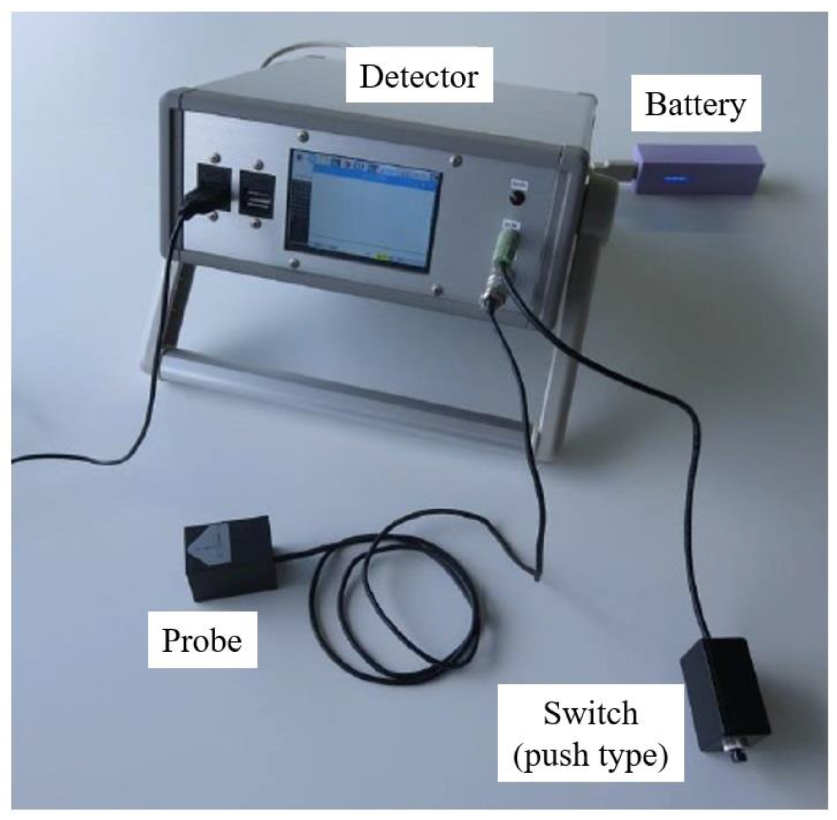
Figure 2 illustrates the developed identification system for short-circuit fault points in concentrated stator windings. The system mainly consists of five components: an oscillator, a drive unit, a control unit, a control panel, and a PC. Figure 3 displays the appearance of the system except the oscillator. The function of each component is described subsequently.
The oscillator supplies current to the stator winding, resulting in the generation of magnetic flux density. The output terminal from the oscillator is connected to the terminal of the concentrated stator winding. The frequency of the AC voltage to be applied to the stator windings is predetermined on the PC side, and the information is transmitted to the oscillator to generate a magnetic field around the windings. The amplitude of the AC voltage from the oscillator is 2 V.
The drive unit controls the position of the search coil. It consists of a search coil and two stepper motors (PJP28T40E16, 3.23 V, 0.95 A, Nippon Pulse Motor, Tokyo, Japan). The search coil serves as a sensor of the magnetic flux density generated by the stator winding, which is composed of a wire conductor wound on an acrylic rod, as illustrated in Figure 4. Each stepper motor can move the search coil in the rotational and longitudinal directions independently.
The control unit has a programmable logic controller to control the stepper motors. The position of the search coil can be adjusted by signals sent from the controller to the stepper motors, where the measurement of magnetic flux density is performed. The search coil can be moved at 1 mm intervals in the longitudinal direction of the teeth and at 1° intervals in the circumferential direction. For reliable measurement, the search coil remains stationary for 0.2 s at each measurement point.
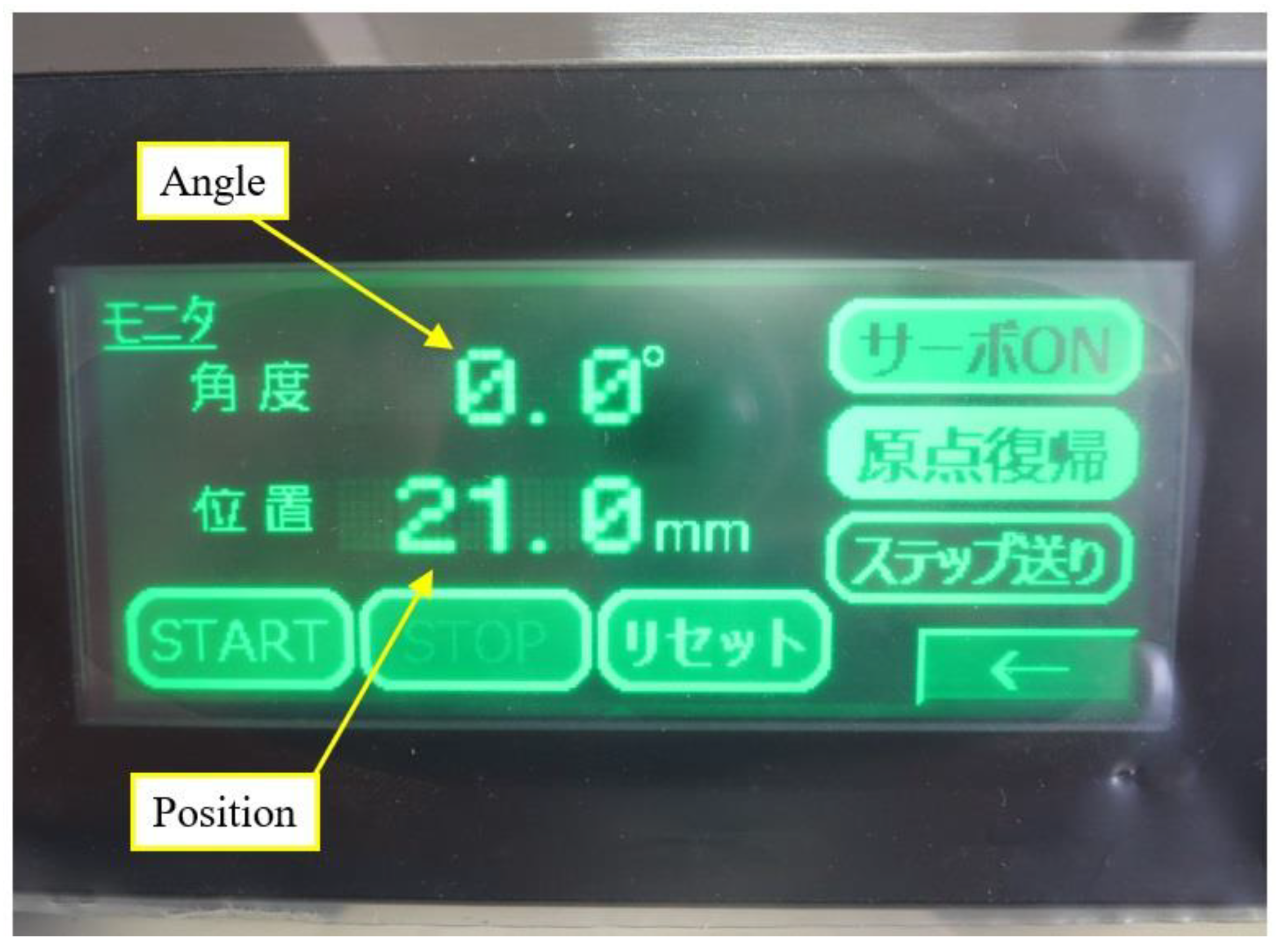
On the control panel screen, the operational commands of the rotation angle and movement distance of the search coil can be input, as illustrated in Figure 5, and the current position of the search coil during measurement is displayed.
When the system is under operation, the position of the search coil is indicated on the control panel by the circumferential angle and longitudinal distance. As the drive unit sequentially moves the search coil, the information on the control panel changes accordingly.
The PC displays the value of magnetic flux density measured and saves both data of the search coil position and magnetic flux density. An example of the PC screen is displayed in Figure 6. The waveforms of the voltage applied to the winding and the output voltage of the search coil are displayed at the top of the screen. The waveform in the middle of the screen displays the output voltage of the search coil after passing through a low-pass filter to remove noise. Finally, the phase difference between the voltage measured by the search coil and the applied voltage is calculated, and the polarity of the voltage measured by the search coil is determined and visualized at the bottom of the screen.
In this case, the PC screen before starting the measurement is illustrated. When the measurement starts, the visualization of the distribution of the magnetic flux density disappears, and different colors are displayed at corresponding positions on the screen, depending on the value of the magnetic flux density at the measurement points on the teeth. Continuous-tone color is adopted, namely dark green when the output voltage from the search coil is −50 mV and orange when the output voltage from the search coil is 50 mV. The voltage measured by the search coil can be calibrated and converted into magnetic flux density. However, in this study, this conversion is not performed, and the voltage output from the search coil is directly used as the magnetic flux density. Data related to the voltage applied to the windings, magnetic flux density, and search coil position are all stored on the PC.
4. Verification Test
4.1. Orbit Setting of Search Coil
To verify the validity of the prototype system, tests were conducted using the stator windings employed in hybrid electric vehicles. These tests were conducted on the stator windings both in a normal state and with a one-turn short circuit. Each phase of the teeth was repeated in the order of U, V, and W in the rotation direction. In this test, a one-turn short-circuit fault was intentionally created 20 mm from the inside to the outside of Tooth No. 2, corresponding to the V phase. As the stator winding employed in the test had 18 teeth, the search coil was moved at angular intervals of 20° in the circumferential direction to move directly above each tooth. In addition, the coil was moved at intervals of 2 mm in the longitudinal direction.
4.2. Test Results
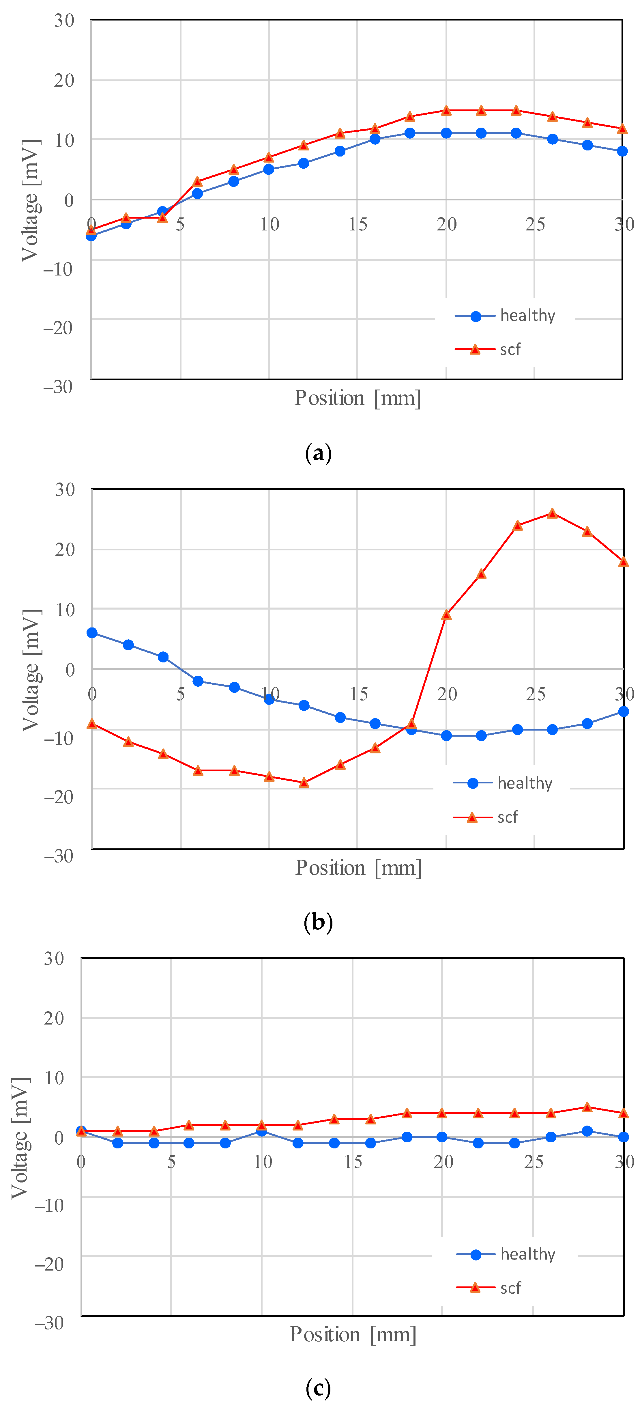
The search coil was initially positioned at the center of the inner side of the teeth at 0 mm, as illustrated in Figure 7. The magnetic flux density was measured at points from the inside toward the outside of the teeth. When a short-circuit fault occurs in a concentrated winding, the direction of the magnetic flux density becomes opposite to that observed under normal conditions at that point [21]. Based on this principle, the results from the search coil observed around Teeth Nos. 1–3 were examined for both the normal and short-circuit states when AC voltage was applied between U–V, V–W, and W–U. The output voltages are presented in Figure 8, Figure 9 and Figure 10. The voltage observed around Teeth Nos. 4–18 was the same as that observed around Teeth Nos. 1–3 and was thus omitted for the sake of brevity.
In Figure 8, Figure 9 and Figure 10, the horizontal axis represents the distance from the inside of the teeth toward the outside, while the vertical axis represents the voltage observed by the search coil, which is proportional to the magnetic flux density. The results indicate that the distribution of magnetic flux density throughout the stator changed due to the short circuit in the winding. Notably, as illustrated in Figure 8, the magnetic flux density of Tooth No. 2 (displayed in Figure 8b) changed from negative to positive at approximately 20 mm, in contrast to the normal winding. This indicates that the direction of the magnetic field was reversed at this position, signifying that the short-circuit fault occurred here.
Similarly, Figure 9 displays the magnetic flux density around Teeth Nos. 1–3 when an AC voltage was applied between the V and W phases. Similar to Figure 8, in Tooth No. 2 (displayed in Figure 9b), the magnetic flux density changed from positive to negative at approximately 20 mm, indicating that a short-circuit fault occurred at this point.
Figure 10 presents the magnetic flux density around Teeth Nos. 1–3 when an AC voltage was applied between the W and U phases. The short-circuit fault was generated in the V phase. Therefore, when an AC voltage was applied between the W and U phases displayed in Figure 10, no current flowed through the coil of Tooth No. 2. Consequently, in Tooth No. 2 in Figure 10b, the observed magnetic flux density was almost zero regardless of the winding condition.
Figure 11 presents a three-dimensional representation of the magnetic flux density on all the teeth between U and V. In this figure, the x- and y-axes denote the positions of the stator windings. However, as described in Section 4.2, the search coil moves from the inside of the teeth toward the outside. Therefore, the origin is the center point inside each tooth. The z-axis denotes the output voltage from the search coil, which is proportional to the magnetic flux density.
As illustrated in Figure 8, the magnetic flux density in the teeth takes a positive value for Tooth No. 1, a negative value for Tooth No. 2, and a value of zero for Tooth No. 3. This trend is repeated for Teeth Nos. 4–18. As a result, six peaks and six valleys appear in the distribution in Figure 11. The left side of Figure 11 displays the results when the winding is normal, while the right side displays the results when the winding is short-circuited. The red arrow indicates the point where the short-circuit fault occurs. Comparing the two results reveals that the magnetic flux density changes considerably at the point where the short-circuit fault occurs. Consequently, it becomes possible to identify easily and visually the position of a short circuit in the teeth.
5. Discussion
In this study, the position of the search coil was controlled by stepper motors. When the magnetic flux density induced by a short circuit was measured, the stepper motors were fixed at the measurement position but became excited. Therefore, the magnetic field generated by the excited stepper motors may affect the measurement results. Here, the effect of the stepper motors on the measurements is discussed in terms of the distance dependence of the magnetic flux density due to the stepper motors. The same stepper motor as described in Section 3 was employed. The magnetic flux density was measured using the sensor illustrated in Figure 12, which was developed in a previous study [22].
First, the magnetic sensor probe was placed adjacent to the stepper motor, as illustrated in Figure 13. The distance dependence of the magnetic flux density was measured twice in the perpendicular direction to the motor axis. The results are presented in Table 1. Very similar results were obtained in the two trials. The magnetic flux density decreases as the distance from the stepper motor increases. Since the background magnetic flux density is approximately 0.1 µT, it is considered that 60 mm is suitable for avoiding the effect of the magnetic field generated by the motor.
Next, the magnetic flux density was measured twice by changing the distance in the axial direction of the motor, as illustrated in Figure 14. The results in Table 2 demonstrate that the magnetic flux density is almost the same as the background value.
According to the aforementioned results, the effect of the magnetic field generated by the stepper motor becomes negligible 60 mm away from it. The developed identification system described in Section 3 enables the detection of short circuits in the motor windings using the magnetic flux density because the distance between the search coil and the stepper motor is at least 60 mm.
6. Conclusions
The experiments demonstrated clearly that the magnetic flux density near the motor windings is sensible for one-turn short circuits. A simple magnetic field sensor and its precise positioning with stepper motors enabled the highly reliable identification of the short-circuit fault points in concentrated stator windings based on the magnetic flux density distribution. The proposed method has flexibility and adaptability regarding operation because the size of the field sensor and the number of measuring points regarding the magnetic flux density can be changed easily depending on the type and/or the size of the target motor windings. Use of the proposed method will be expected in shipping and periodic inspections of motor windings. The reliable product management of motors, such as the improvement of the electrical insulation and the revision of the manufacturing process, may also be achieved based on the analysis of the short-circuit points in the windings.
Future work will focus on improving the efficiency of the system. It takes approximately 570 s to measure the magnetic flux density for all 18 teeth. Furthermore, to ensure the reliable measurement of the magnetic flux density, the search coil is stopped for 0.2 s at each measurement point. It is anticipated that the time can be considerably reduced by providing the same number of search coils as the number of teeth.
Author Contributions
Conceptualization, H.N. and Y.M.; methodology, H.N.; software, H.N.; validation, H.N. and Y.M.; formal analysis, H.N. and Y.M.; investigation, H.N. and Y.M.; resources, H.N.; data curation, H.N.; writing—original draft preparation, H.N. and Y.M.; writing—review and editing, H.N. and Y.M.; visualization, H.N.; supervision, H.N. and Y.M.; project administration, H.N.; funding acquisition, H.N. All authors have read and agreed to the published version of the manuscript.
Funding
This research received no external funding.
Data Availability Statement
The original contributions presented in the study are included in the article, further inquiries can be directed to the corresponding author.
Conflicts of Interest
The authors declare no conflicts of interest.
References
- Albrecht, P.F.; Appiarius, J.C.; McCoy, R.M.; Owen, E.L.; Sharma, D.K. Assessment of the Reliability of Motors in Utility Applications -Updated. IEEE Trans. Energy Convers. 1986, 1, 39–46. [Google Scholar] [CrossRef]
- IEEE Motor Reliability Working Group. Report of large motor reliability survey of industrial and commercial installations. IEEE Trans. Ind. Appl. 1985, 1A-21, 853–872. [Google Scholar]
- Aubert, B.; Régnier, J.; Caux, S.; Alejo, D. Kalman-filter-based indicator for online interturn short circuits detection in permanent-magnet synchronous generators. IEEE Trans. Ind. Electron. 2015, 62, 1921–1930. [Google Scholar] [CrossRef]
- Barcelos, A.S.; Cardoso, A.J.M. Current-Based Bearing Fault Diagnosis Using Deep Learning Algorithms. Energies 2021, 14, 2509. [Google Scholar] [CrossRef]
- Chen, L.; Shen, J.; Xu, G.; Chi, H.; Feng, Q.; Zhou, Y.; Deng, Y.; Wen, H. Induction Motor Stator Winding Inter-Tern Short Circuit Fault Detection Based on Start-Up Current Envelope Energy. Sensors 2023, 23, 8581. [Google Scholar] [CrossRef] [PubMed]
- Kim, T.; Lee, H.; Kwak, S. The internal fault analysis of brushless DC motors based on the winding function theory. IEEE Trans. Magn. 2009, 45, 2090–2096. [Google Scholar]
- Kim, K.; Park, J.; Hur, J.; Kim, B. Comparison of the fault characteristics of IPM-type and SPM-type BLDC motors under inter-turn fault conditions using winding function theory. IEEE Trans. Ind. Appl. 2014, 50, 986–994. [Google Scholar] [CrossRef]
- Mei, Z.; Li, G.J.; Zhu, Z.Q.; Clark, R.; Thomas, A.; Azar, Z. Scaling Effect on Inter-Turn Short-Circuit Fault of PM Machines for Wind Power Application. IEEE Trans. Ind. Appl. 2023, 59, 789–800. [Google Scholar] [CrossRef]
- Ge, B.; Xiao, S.; Liu, Z.; Tao, D.; Sun, X. Improved model of synchronous generators internal faults based on circuit-coupled FEM. IEEE Trans. Energy Convers. 2017, 32, 876–884. [Google Scholar] [CrossRef]
- Berzoy, A.; Mohamed, A.A.S.; Mohammed, O. Impact of inter-turn short-circuit location on induction machines parameters through FE computations. IEEE Trans. Magn. 2017, 53, 8105504. [Google Scholar] [CrossRef]
- Garcia-Calva, T.A.; Morinigo-Sotelo, D.; Duque-Perez, O.; Garcia-Perez, A.; Romero-Troncoso, R.d.J. Time-Frequency analysis based on minimum norm spectral estimation to detect induction motor faults. Energies 2020, 13, 4102. [Google Scholar] [CrossRef]
- Gyftakis, K.N.; Garcia-Calva, T.A.; Skarmoutsos, G.A.; Morinigo-Sotelo, D.; Mueller, M.; de Jesus Romero-Troncoso, R. Demagnetization Monitoring Identification in PM Generators with Concentrated Windings During Transient Conditions. IEEE Trans. Ind. Appl. 2023, 59, 1510–1518. [Google Scholar] [CrossRef]
- Mugarra, A.; Mayora, H.; Guerrero, J.M.; Platero, C.A. Frequency Response Analysis (FRA) Fault Diagram Assessment Method. IEEE Trans. Ind. Appl. 2022, 58, 336–344. [Google Scholar] [CrossRef]
- Zheng, D.; Lu, G.; Zhang, P. An Improved Online Stator Insulation Monitoring Method Based on Common-Mode Impedance Spectrum Considering the Effect of Aging Position. IEEE Trans. Ind. Appl. 2022, 58, 3558–3566. [Google Scholar] [CrossRef]
- Nakamura, H.; Asano, K.; Usuda, S.; Mizuno, Y. A Diagnosis Method of Bearing and Stator Fault in Motor Using Rotating Sound Based on Deep Learning. Energies 2021, 14, 1319. [Google Scholar] [CrossRef]
- Wiedenbrug, E.; Frey, G.; Wilson, J. Early Intervention. IEEE Ind. Appl. Mag. 2004, 10, 34–40. [Google Scholar] [CrossRef]
- Hioki, E.E. Corporation. Available online: https://www.hioki.com/us-en/products/electrical-safety-testers/impulse/id_6745 (accessed on 23 March 2024).
- Grubic, S.; Restrepo, J.; Aller, J.M.; Lu, B.; Habetler, T.G. A New Concept for Online Surge Testing for the Detection of Winding Insulation Deterioration in Low-Voltage Induction Machines. IEEE Trans. Ind. Appl. 2011, 47, 2051–2058. [Google Scholar] [CrossRef]
- Nakamura, H.; Mizuno, Y. Method for Diagnosing a Short-Circuit Fault in the Stator Winding of a Motor Based on Parameter Identification of Features and a Support Vector Machine. Energies 2020, 13, 2272. [Google Scholar] [CrossRef]
- Ohki, Y. News from Japan. IEEE Electr. Insul. Mag. 2016, 32, 56–58. [Google Scholar] [CrossRef]
- Nakamura, H. Proposal of Method for Identifying Short-Circuit Fault Points in Concentrated Winding of Motor Stators. IEEJ Trans. Ind. Appl. 2018, 138, 623–629. (In Japanese) [Google Scholar] [CrossRef]
- Nakamura, H.; Mizuno, Y.; Pandarakone, S.E. Development of High-Performance Magnetic Field Sensor and Its Application to a Magnetic Field Visualization System Using the Augmented Reality Technique. J. Sens. 2019, 2019, 5848514. [Google Scholar] [CrossRef]
Figure 1.
Schematic changes in winding configuration induced by a short-circuit fault. (a) Healthy winding (No fault); (b) One-turn short-circuit; (c) Formation of closed-loop coil in winding.
Figure 1.
Schematic changes in winding configuration induced by a short-circuit fault. (a) Healthy winding (No fault); (b) One-turn short-circuit; (c) Formation of closed-loop coil in winding.

Figure 2.
Specifications of identification system for short-circuit fault points.

Figure 3.
Developed identification system for short-circuit fault points.

Figure 4.
Search coil in drive unit.

Figure 5.
Control panel.

Figure 6.
PC screen.

Figure 7.
Measured points on each tooth.

Figure 8.
Measured voltage on each tooth (U–V). (a) Tooth No. 1; (b) Tooth No. 2; (c) Tooth No. 3.

Figure 9.
Measured voltage on each tooth (V–W). (a) Tooth No. 1; (b) Tooth No. 2; (c) Tooth No. 3.

Figure 10.
Measured voltage on each tooth (W–U). (a) Tooth No. 1; (b) Tooth No. 2; (c) Tooth No. 3.

Figure 11.
Change in the magnetic flux density distribution due to a short-circuit fault (U–V). The magnitude of the magnetic flux density is indicated with continuous-tone color. The red arrow indicates the short-circuit fault point.
Figure 11.
Change in the magnetic flux density distribution due to a short-circuit fault (U–V). The magnitude of the magnetic flux density is indicated with continuous-tone color. The red arrow indicates the short-circuit fault point.

Figure 12.
Magnetic field sensor developed in a previous study [22].
Figure 12.
Magnetic field sensor developed in a previous study [22].

Figure 13.
Distance from the side direction of the stepper motor.

Figure 14.
Distance from the axial direction of the stepper motor.


Table 1.
Measured values of magnetic flux density [µT] (perpendicular direction).
| Trial | Distance [mm] | |||
|---|---|---|---|---|
| 0 | 20 | 40 | 60 | |
| 1 | 15.02 | 2.27 | 0.58 | 0.18 |
| 2 | 14.97 | 2.29 | 0.60 | 0.16 |
Table 2.
Measured values of magnetic flux density [µT] (axial direction).
| Trial | Distance [mm] | ||
|---|---|---|---|
| 25 | 40 | 60 | |
| 1 | 0.13 | 0.13 | 0.12 |
| 2 | 0.15 | 0.22 | 0.12 |
Disclaimer/Publisher’s Note: The statements, opinions and data contained in all publications are solely those of the individual author(s) and contributor(s) and not of MDPI and/or the editor(s). MDPI and/or the editor(s) disclaim responsibility for any injury to people or property resulting from any ideas, methods, instructions or products referred to in the content. |
© 2024 by the authors. Licensee MDPI, Basel, Switzerland. This article is an open access article distributed under the terms and conditions of the Creative Commons Attribution (CC BY) license (https://creativecommons.org/licenses/by/4.0/).
Share and Cite
MDPI and ACS Style
Nakamura, H.; Mizuno, Y. Identification System for Short-Circuit Fault Points in Concentrated Stator Windings of Motors. Energies 2024, 17, 1984. https://doi.org/10.3390/en17091984
AMA Style
Nakamura H, Mizuno Y. Identification System for Short-Circuit Fault Points in Concentrated Stator Windings of Motors. Energies. 2024; 17(9):1984. https://doi.org/10.3390/en17091984
Chicago/Turabian StyleNakamura, Hisahide, and Yukio Mizuno. 2024. "Identification System for Short-Circuit Fault Points in Concentrated Stator Windings of Motors" Energies 17, no. 9: 1984. https://doi.org/10.3390/en17091984
Note that from the first issue of 2016, this journal uses article numbers instead of page numbers. See further details here.