Review

Insulation for Rotating Low-Voltage Electrical Machines: Degradation, Lifetime Modeling, and Accelerated Aging Tests

by
Xuanming Zhou
1,
Paolo Giangrande
2,*,
Yatai Ji
3,
Weiduo Zhao
1,
Salman Ijaz
4 and
Michael Galea
5
1
Key Laboratory of More Electric Aircraft Technology of Zhejiang Province, University of Nottingham Ningbo China, Ningbo 315100, China
2
Department of Engineering and Applied Sciences, University of Bergamo, 24100 Bergamo, Italy
3
Department of Electrical Engineering, Tsinghua University, Beijing 100084, China
4
Control System Laboratory, University of Nottingham Ningbo China, Ningbo 315100, China
5
Department of Electrical Engineering, University of Malta, 650000 Valletta, Malta
*
Author to whom correspondence should be addressed.
Energies 2024, 17(9), 1987; https://doi.org/10.3390/en17091987
Submission received: 17 March 2024 / Revised: 15 April 2024 / Accepted: 19 April 2024 / Published: 23 April 2024
(This article belongs to the Special Issue Reliability and Condition Monitoring of Electric Motors and Drives)

Abstract

:
The low-voltage electric machine (EM) is a core technology for transportation electrification, and features like high power density and compact volume are essential prerequisites. However, these requirements are usually in conflict with the reliability property of EM, especially in the safety-critical industry such as aviation. Therefore, an appropriate balance between high-performance and reliability needs to be found. Often, the over-engineering method is applied to ensure safety, although it might have a detrimental effect on the EM volume. To address this issue, the EM reliability assessment is included at the EM design stage through the physics of failure (PoF) theory. In EMs, the windings play a key role in electromechanical energy conversion, but their insulation system is subject to frequent failure and represents a reliability bottleneck. Therefore, in-depth research on the root causes of insulation breakdown is beneficial for EM reliability improvement purposes. Indeed, increasing awareness and knowledge on the mechanism of the insulation degradation process and the related lifetime modeling enables the growth of appropriate tools for achieving reliability targets since the first EM design steps. In this work, the main aspects of the insulation system, in terms of materials and manufacturing, are first reviewed. Then, the principal stresses experienced by the winding insulation system are deeply discussed with the purpose of building a profound understanding of the PoF. Finally, an overview of the most common insulation lifetime prediction models is presented, and their use for accomplishing the reliability-oriented design (RoD) and the remaining useful life (RUL) estimation are examined.

1. Introduction

Nowadays, transportation electrification has been becoming increasingly common in our daily lives and has made a great contribution to reducing greenhouse gas emissions and fuel consumption [1]. The electrical machine (EM) serves as one of the most important parts for achieving electrified transportation [2,3], and its performance is frequently pushed to the design limited for achieving more power density in a constrained volume [4,5]. However, EM performance is usually compromised by insulation over-engineering, which prevents an optimal design (e.g., thicker insulation and lower winding temperature) [6]. Therefore, a more careful methodology is advised, aiming at reaching a trade-off between performance and demanded reliability level and enabling appropriate insulation exploitation.
Generally, EM’s principal failures are either of a mechanical or electrical nature; the former mostly involves the bearings, whereas the latter affects the winding insulation. Research on bearings failures is relatively mature enabling a deep understanding of the physical degradation processes, which in turn allowed the development of advanced monitoring techniques [7,8]. For this reason, the mechanical failures are not included here, and focus is given to only winding insulation failures. In low-voltage (LV) EM, the failure probability of winding insulation is around 36% of the total failures [9], while the corresponding value is boosted up to 66% for high-voltage (HV) EM [10]. The detail failure percentages of the various EM components are listed in Table 1.
Increased DC bus voltage and wide bandgap devices enhance the partial discharge (PD) activity increasing the vulnerability of the insulation system [11,12], which becomes the bottleneck for EM reliability. According to IEC standards, the insulation systems could be classified as Type I and Type II insulation systems. Type I insulation systems are commonly made with polymers like polyetherimide (PEI) and polyimide, which are assumed to have failed once PD is triggered. On the other hand, Type II insulations, such as the mica and aramid-based paper, feature the ability to operate under the PD regime [13,14]. Sometimes, an extra inorganic layer (i.e., inorganic over-coat) is added to the organic base-coat to enhance the capability of withstanding PD activity (i.e., corona-resistant wires).
Normally, EM windings withstand a synergistic aging effect from four kinds of stresses: thermal, electrical, mechanical, and ambient (TEAM). Thus, the winding insulation is gradually degraded from healthy condition to failure according to a peculiar trend driven by the TEAM stresses experienced throughout the EM service. In practice, a constant failure rate is often assumed, which might lead to significant discrepancies between actual and predicted lifetime [15]. At present, the failure rate data sets for EMs are outdated due to technological advancements in the fields of materials and control strategies. For this reason, they are not suitable for the new generation of EMs employed in transportation applications. A more effective and innovative strategy to identify the failure rate and ensure an appropriate reliability level consists of relying on the physics of failure (PoF) philosophy [16,17]. PoF is not an entirely new concept since it has been successfully applied to power electronics devices and bearings [16,18,19], and mature know-how has been achieved for practical applications. Nevertheless, the extension of PoF to EM winding is relatively new. Since the insulation winding system is subjected to independent or combined stresses, it is hard to describe the actual degradation process by a simple equation [6,7]. The complexity arises from the multitude of phenomena involved, emphasizing the inherently multi-physics nature of the challenge [20]. Under the assumption of a dominant stress, a single stress aging model might represent a potential solution, although its suitability and accuracy are challenged by the mutual contribution of the ambient stresses (e.g., low pressure, moister, etc.).
Assuming the insulation system as the primary failure point, a PoF-based design strategy has the potential to significantly enhance EM lifetime and reliability [17,21]. However, conducting real PoF-based analyses requires the availability of a wide range of data, but magnet wire (i.e., enameled wire for EM winding) and insulation manufacturers only provide basic information such as thermal class and grade. In essence, there is a lack of data on “lifetime” and “degradation” to conduct a precise PoF-based assessment without extra experimental tests. Consequently, Accelerated Lifetime Testing (ALT) [22] is required in order to have available a complete set of experimental data and perform a comprehensive statistical analysis. Specifically, regarding winding insulation, in accordance with technical standards [23] and supported by practical experience [6], it is important to note that the insulation lifetime of magnet wire can substantially differ from that of the EM in which it is installed. Indeed, the winding insulation lifetime assessment accounts only for electrical failures, while an EM might experience failures of other nature (e.g., mechanical failures).
In the early age, EM lifetime research focuses on HV EMs such as fans, power plant generators, etc. Nevertheless, the insulation materials employed in HV EMs differ in terms of composition from those typical of LV EMs. Indeed, Type II insulation materials are adopted in HV EMs, as prescribed by the technical standard [24], and their main source of degradation is represented by electrical stress. Accordingly, the related lifetime research has some referential value but could not be directly applied to LV EMs. For the LV EM insulation, the lifetime estimation based on accelerated thermal aging tests at constant temperature is investigated in [6,22,25]. In [25], the PoF method is applied to the EM design, and case studies are presented to prove the PoF applicability. Different from HV applications where the EM is likely to experience a continuous service, LV EMs meant for transport applications, such as electric vehicle (EV), electrical vertical take-off and landing aircraft (eVTOL), more electric aircraft (MEA) and rail traction, operate with an intermittent duty. Consequently, frequent starts and stops lead to variable temperature profiles (TP), and results coming from constant temperature thermal aging tests might affect the reliability assessment [20,26]. In this scenario, cyclic temperature thermal aging tests might deliver more suitable outcomes, as proven in [26,27,28]. Considering traction motors, intensive numerical analyses are performed in [29,30] to assess the insulation fatigue caused by periodic temperature cycles. In [31,32], a substantial reduction in lifetime due to the thermal cycling effect is revealed, and the mismatch between loss-of-life and Arrhenius’s equation is observed. The mentioned papers on lifetime prediction and reliability research highlight the demand for further efforts in this field to acquire a more comprehensive understanding of insulation degradation.
In this paper, an overview of insulation challenges and potential solutions is presented, focusing on LV EMs for transportation electrification. The LV insulation system is comprehensively reviewed in Section 2. Then, the degradation and aging stresses are introduced and discussed in Section 3. Based on the stress analysis, the corresponding lifetime models are reviewed in Section 4, and the associated accelerated aging tests are examined in Section 5. Finally, the reliability-oriented design (RoD) and the remaining useful life (RUL) methodologies are analyzed in Section 6, proving their effectiveness as viable strategies for ensuring reliability.

2. EM Development and Insulation System

2.1. EM Modern Applications

In EMs history, their volume is reducing for the same power, i.e., the power density is increasing due to the EM technology developments [33]. With the increasing maturity of EM technology and the ongoing trend of decreasing carbon emissions, a transition from internal combustion engines to high-performance EMs is recently taking place in the automotive sector [34]. In parallel to the electrification of the automobile, the aerospace sector is also experiencing a shift towards more electric solutions driven by the desire for performance enhancement and the need to reduce operating and maintenance expenses [35]. The introduction of MEA initiatives has led to a predominant use of electric drive systems over other secondary power sources such as mechanical, pneumatic, and hydraulic power, resulting in reduced weight of airborne equipment systems [36]. Over time, this progression has significantly increased the proportion of electric components in onboard systems, as depicted in Figure 1 [37].
The MEA can be defined as incorporating a high-capacity power supply system and electric power actuation technology. For example, the Electric Taxiing System is a significant advancement in aircraft dispatch systems, reducing carbon emissions while increasing efficiency and lowering systematic complexity [38]. Simultaneously, the concept of all-electric aircraft (AEA) has been proposed to replace traditional air-breathing fuel engines. Under this concept, eVTOL aircraft is an emerging industry that will soon be used for commercial operations with EMs as their primary means of propulsion. Unlike motors in electric vehicles, eVTOLs require high-torque and low-speed motors to reduce propeller tip speed and noise [1,39].
With the ongoing trend, the requirements for power (and torque) per unit weight and/or volume of EMs are becoming increasingly stringent [40]. Additionally, apart from performance considerations, safety is also a crucial aspect of the aerospace industry. Unfortunately, reducing failure probability comes at the cost of sacrificing power density in EMs. Several methods to enhance EM power density and performance include advanced cooling systems, boosted DC voltage link values, and utilization of fast switching devices [41]. However, these choices elevate the stress levels, introducing potential side effects on winding insulation systems, which might result in a shorter lifetime for EMs.

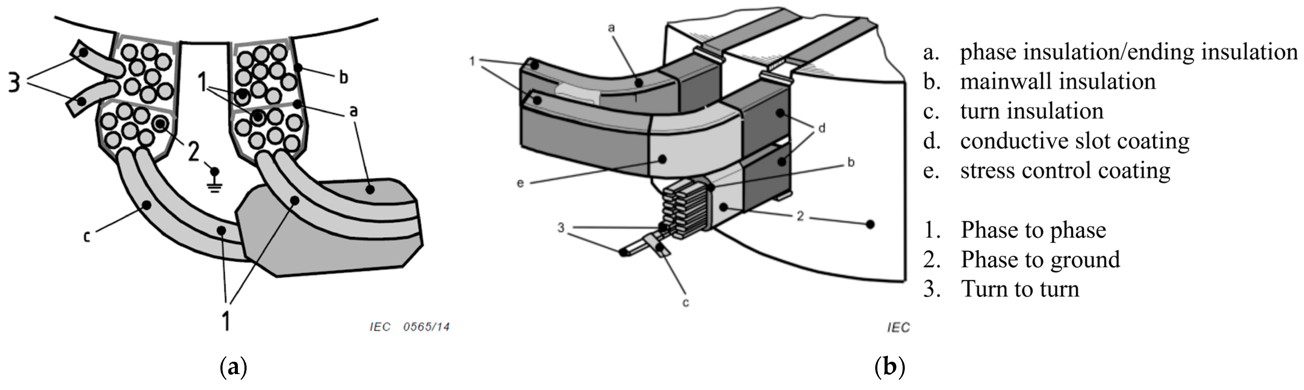
2.2. Winding and Insulation System

The winding, as one of the most critical components, plays a pivotal role in ensuring the EM functionality and the electric insulation system (EIS) is responsible for the dielectric capability of windings [42]. Thus, the design of EMs requires careful consideration of the quality and performance of their EIS, two common configurations of EIS system are shown in Figure 2. The development of insulation materials has kept pace with advancements in electrical equipment, with increasing amounts of synthetic materials becoming available. Important characteristics of electrical insulation materials include dielectric strength, resistivity, dielectric constant or relative permittivity, and dielectric power loss [43]. The type and amount of insulation material required for a given application dictate the size and operating limitations of the equipment [30].
Modern materials include high-temperature polymers, such as polyamideimide (PAI) and polyetherimide (PEI), which are classified as Type I insulation materials, e.g., coating of the copper conductors used in LV EMs [45]. On the other side, mixed organic/inorganic materials (Type II), such as polyamide, plastic, rubber, and inorganic substances (such as silicone and nanocomposites) [46], are preferred in HV EM due to the capability of withstanding PD activity. The degradation level of the Type II insulation system varies depending on the types of PD, i.e., surface charge, slot discharge, corona discharge at the slot exit, and bar-to-bar discharge [47,48]. Therefore, the maintenance scheduling and procedure are not only determined by the PD amplitude, but also by the occurring PD types [49]. In the aerospace industry, corona-resistant wires using Polyvinyl Chloride, PAI, silica gel, and PEI are normally employed. Apart from these materials, fluoro-polymers, like Polyfluorinated Ethylene and Ethyl Tetra Fluoro Ethylene, have progressively taken over conventional insulating materials due to their exceptional mechanical properties and heat resistance [50].
As shown in Figure 2, there are commonly two kinds of windings: random-wound windings and form wound windings [24]. Random-wound winding is usually applied on LV EMs with a rated voltage below 1 kVrms [51], and three subsystems (i.e., turn-to-turn, phase-to-phase and phase-to-ground) are identified. In the subsystems, many different components exist, such as slot liner, separator, wedge, phase separator, coil-nose tapes, and bracing [52]. Research on different insulation components is summarized as following three points:
  • The enameled round wires (i.e., round copper conductors insulated by the organic insulation) ensure the insulation among turns, and turn-to-turn insulation breakdown might quickly escalate to more severe failures [53]. For this reason, several investigations are focused on the dielectric behavior of inter-turn insulation [11,54,55];
  • The phase-to-phase insulation consists of an insulation paper sheet, which is located between the phase’s coils, increasing the dielectric strength [56]. Phase separators are also placed in the end winding region [57,58], where the probability of failure occurrence is higher. Common insulation papers are made of aramid (i.e., Nomex in Dupont trade), polyester film (Mylar), or polyester fleece (Dacron) [52];
  • The phase-to-ground insulation also employs insulation paper, namely slot liner, to prevent contact between coils and the stator core. The slot liner’s thickness depends on the voltage class of EMs [59], and a possible failure triggers an asymmetric fault.
Random-wound windings are often impregnated with epoxy-based resins, which are applied via a trickle process to increase the level of protection against ambient contamination and moisture corrosion [60]. Apart from the trickle process, the random-wound windings impregnation is also obtained through a dipping process, although this might result in an irregular distribution of the resin between turns [61]. The salient aspects regarding the insulation subsystems and materials are summarized in Table 2.
Random-wound windings offer flexibility in selecting the number of conductors within the slot, allowing a versatile optimization of the EM electromagnetic design [62]. Further, smaller conductors’ diameters contribute to AC power loss reduction. However, the turn with the highest electric potential (i.e., input terminal) might likely be adjacent to the one at the lowest electric potential (i.e., neutral point) in random-wound windings [63]. Therefore, the enameled wire grade (i.e., insulation thickness) selection is critical for enabling the appropriate voltage withstand capability. Indeed, phase-to-phase and phase-to-ground failures are the generally originated as escalation of an initial turn-to-turn fault, which is triggered by repeated temperature rising and/or PD inception [64].
Form-wound windings (Figure 2b) are commonly employed in EMs with a rated voltage higher than 1 kVrms [51], and the conductors are pre-shaped and covered by polyimide film before being placed into the stator slots. In this arrangement, a degree of control on the voltage difference between adjacent turns is permissible due to the predefined position of the coil conductors [65]. Therefore, the risk of turn-turn short-circuits and PD inception can be easily minimized by coordinating the effective turn insulation material and thickness.
In e-mobility applications, a new winding solution, namely hairpin winding, is adopted by many manufacturers due to the faster takt time and the assembling process automatization [66]. The hairpin winding is composed of rectangular conductors and shares similarities with the form-wound winding, as shown in Figure 3. From the design perspective, the great benefit of hairpin winding is represented by the possibility of reaching fill factor values up to 70%, which improves the EM power density. An illustrative evaluation of the achievable slot fill factor is reported in Figure 4, where the hairpin winding solution is compared against the random-wound one. It is important to underline that the rectangular conductor requires a lower insulation material per unit copper volume and delivers better heat dissipation performance [67]. The latter aspect contributes either to lowering the thermal stress and extending the EIS lifetime or to increasing the current density for a more compact design [68]. Another advantage of the hairpin winding is the end-winding reduced length that leads to shorter axial length and smaller copper loss. Despite the mentioned benefits, the hairpin windings feature a limited number of conductors (i.e., 8–10), resulting in larger copper cross-sections. Consequently, the impact of AC losses becomes more pronounced, especially in high-speed applications [67]. Research on EIS reliability and the aging process of harping windings is currently limited due to the relatively recent adoption of such enabling technology.

3. EM Development and Insulation System

Regardless of the winding configuration, a certain amount of energy is inevitably dissipated as heat during EM operations due to Joule and Iron losses [70]. The thermal stress is further exacerbated by fluctuations in temperature caused by the EM mission profile. Aside from the thermal stress, advanced control technologies such as variable speed drives (VSDs) employing pulse width modulation (PWM) have significantly improved controllability but increased the electrical stress experienced by the EMs [71]. Furthermore, ambient and mechanical stresses might significantly contribute to the EIS deterioration process [72]. Thus, it is crucial to gather information on how TEAM stresses interact with EIS to prevent premature failures [59].

3.1. Thermal Stress and Aging

Thermal degradation is the dominant failure mode in complex polymer insulation materials. The deterioration process is based on an oxidizing reaction and material decomposition [73]. In this process, a large amount of gaseous, liquid, and solid products is produced. When the temperature rises above an approximate value of 160 °C, volatiles solvents start turning into gases, while a temperature of 180 °C causes the chemical decomposition of the insulation resin. Additionally, more massive compounds in the resin reach the boiling temperature point, and heavier hydrocarbon gases, such as ethylene, are generated [74]. Over a long time-span, the pyrolyzing activity could produce different substances, weakening the dielectric properties and increasing the chance of electrical breakdown. The temperature escalation accelerates the aging process, resulting in a substantial reduction of winding insulation lifetime. As a general rule of thumb, the temperature increase of 10 °C corresponds to a 50% decrease in the insulation lifetime value [75].
In general, thermal aging is a slow process and does not lead to an immediate failure, but the insulation exposed to thermal stress becomes more susceptible to the influence of other stresses. For example, a thermally aged EIS is more prone to PD risk due to thinner insulation thickness [76], as well as the impact of mechanical stress (e.g., vibration) is enhanced by the insulation brittleness triggered by the thermal aging process. Voltage variations and unbalanced phase voltage can activate intense thermal stress, resulting in a significant loss of life. For instance, a 3.5% phase voltage unbalance causes a 25% temperature rise in the phase carrying the highest current [75].

3.2. Electrical Stress and PD

The advent of VSD is also the beginning of considerable electrical stress in LV EM, which is attributable to the repetitive and impulsive shape of the applied voltage. The move from BJT to IGBT and MOSFET resulted in an increased switching frequency that led to several tens of kV/μs rise fronts and a pulse repetition frequency of 50 kHz [22]. Despite the undoubtable improvements in terms of efficiency, lightweight and compact system [77], the breakthrough in wide bandgap (WBG) semiconductors, such as SiC and GaN, amplified the electrical stress.
According to IEC 60034-18-41, the voltage value at the EM terminals may double that at the inverter ones because of the impedance mismatch [14], and this phenomenon is accounted for through the overvoltage factor (OF). An example of how cable length and rise time (i.e., VSD parameters) affect the OF and, consequently, the EM terminal voltage is depicted in Figure 5, where the lowest raise time is equal to 10 ns. In [78], the OF is determined for even lower rise time values (i.e., 6.5 ns). As a consequence, propagation speed v = 1 / L C , where L and C are the line inductance and capacitance), excessively steep voltage pulses also lead to nonlinearity in voltage distribution [79], causing a much higher percentage of voltage concentrated across the initial turns [59].
A source of electrical aging is represented by the tracking process, which is essentially the formation of an instantaneous conductive path on the surface of the insulation material [75]. On the other hand, the PD, i.e., an electric discharge that partially bridges two conductors’ insulation [80], is an indication of electrical stress. According to the IEC standard, partial discharge inception voltage (PDIV) is defined as the minimum voltage level required to trigger the PD activity [14]. Therefore, when the voltage stressing the EIS exceeds the PDIV, the PD is triggered and leads to the end-of-life in Type I insulation or electrical aging in Type II insulation.

3.3. Ambient Stress

Pollution, elevated humidity, corrosive chemicals, radiation in nuclear facilities, or salt concentration in applications near the seashore are grouped as environmental or ambient stress [59]. The individual ambient factor alone may not induce aging, but when combined with other stresses, it can contribute to aging. Consequently, ambient stress is typically regarded as an “influential factor” that contributes to the aging induced by the predominant stress (e.g., temperature, vibration, or voltage amplitude). For instance, dust and impurity contaminations can lead to lower heat dissipation, increasing thermal deterioration. Alternatively, the dust and impurity contaminations contribute to the formation of a thin layer of conductive material [81], which promotes the circulation of surface currents and electrical tracking. Aggressive chemicals make the EIS more susceptible to mechanical stresses [25], while salty working environments compromise the EIS integrity, shortening the EM lifetime [48].
In literature, numerous studies investigate the correlation between ambient factors (i.e., humidity, pressure, ambient temperature, etc.) and PDIV [81,82,83,84,85,86]. Considering EMs for MEA, the low-pressure conditions decrease PDIV value [12,13,83], and severe electrical aging is observed in corona-resistant wires [87,88].

3.4. Mechanical Stress

Mechanical stresses are broadly classified into internal and external stresses [89], where the former is generated by the EM windings (i.e., the electromagnetic force and thermal expansion), while the latter is produced by the surrounding environment (i.e., vibrations) or the EM rotor. The electromagnetic force is directly proportional to the square of the EM current and reaches its maximum magnitude during startup. The ensuing conductor movement poses a risk of insulation damage due to friction.
Internal mechanical stresses can also be thermally induced. In fact, the materials constituting the EIS (e.g., copper and coating layer) feature different thermal expansion coefficients (TECs), and the thermal expansion driven by the temperature generates mutual friction on the contact surface. Silicone, epoxy, and urethane polymers are common resins for impregnation and potting, and they reveal a strong adhesion and retain flexibility even at extremely low temperatures due to the low glass transition temperature (Tg) [63]. These elastomeric properties ensure resistance to cracking during thermal cycling and/or thermal shock. However, aging and operating temperatures above Tg weaken the elastomeric properties, resulting in rigidity and reduced ability to absorb vibration energy [90].
Studies on external mechanical stress are commonly carried out using vibration tables, as depicted in Figure 6, which allow to set amplitude, frequency and acceleration of the applied vibrations [91]. Nevertheless, this approach overlooks potential distortion and attenuation that may occur during vibration transmission and presents challenges in terms of control [92]. An alternative method to apply the mechanical stress to the EIS consists of using vibrating electrodes. Such a choice minimizes distortion and attenuation during vibration transmission [92], although the design of the experiment results is challenging.
Finally, mechanical stress produces microcracks within the insulation layer, which subsequently promotes the PD inception. This represents an example of a synergic effect between mechanical and electrical stresses [93].
Figure 6. External vibration platform [94].
Energies 17 01987 g006

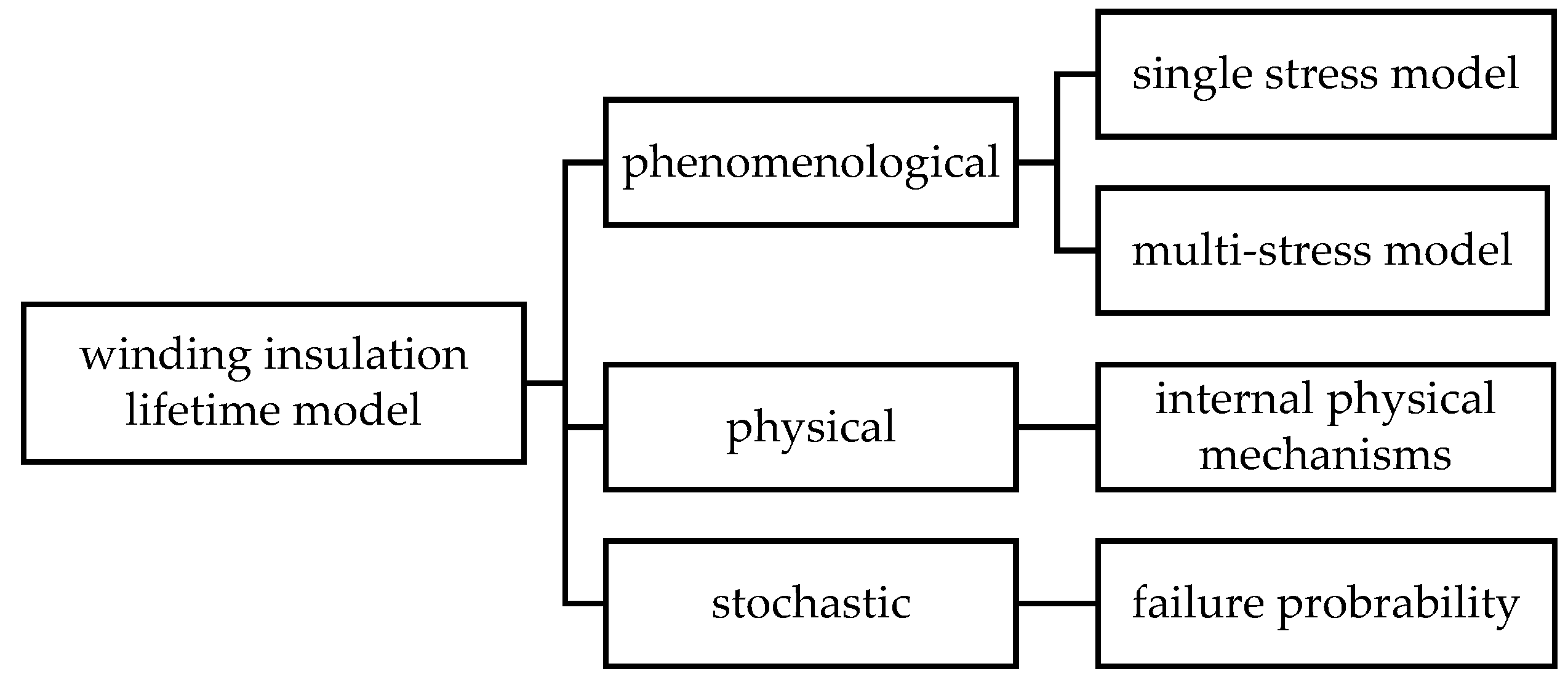
4. Insulation Lifetime Modelling

After reviewing the TEAM stresses, the most popular lifetime modeling methodologies are discussed in this Section.

4.1. Thermal Lifetime Models

4.1.1. Thermal Lifetime Modelling at Constant Temperature

The insulation deterioration modeling is traced back to the 1930s with Montsinger’s [95] and Dakin’s research, where the well-known Arrhenius equation is used to correlate the relationship between thermal aging and chemical reaction rate theory.
L θ = A θ e H k θ
where Lθ is the insulation lifetime expressed in hours, θ is the absolute temperature in K, k is the Boltzmann constant (k = 1.380649 × 10⁻²³ J/K), Aθ is a constant independent of temperature, which depends on the end-of-life criterion of the insulation and the aging process chemical reaction rate constant, and H is the corresponding activation energy in J.
The relationship between log(Lθ) and 1/θ is linear, and this information is often used to verify the consistency between experimental results and theoretical models. According to the research in [96], Eyring proposed a modified Arrhenius equation, which states that the pre-exponential factor Aθ is a function of absolute temperature T, i.e., Aθ = A0θm, where m is a dimensionless constant. Although the updated equation could make a more accurate lifetime prediction, the dimensionless constant is seldom considered since it increases the complexity of the thermal lifetime model. Thermal lifetime models are normally based on the Arrhenius Equation (1), which is often rearranged in the form given in (2).
L θ = L 0 e [ B ( 1 θ 0 1 θ ) ]
where Lθ denotes the insulation lifetime under thermal stress at temperature θ, L0 represents the lifetime at a reference temperature θ0, while the parameter B is associated with the activation energy of the degradation process.

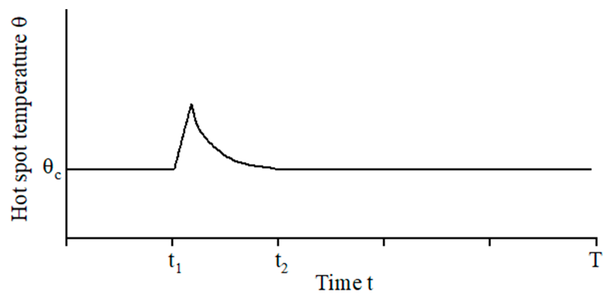
4.1.2. Thermal Lifetime Modelling at Variable Temperature

The thermal lifetime model expressed by (2) is suitable for EMs operating in continuous service since the working temperature is constant. In the case of EMs subject to a variable temperature profile, Equation (2) is combined with the cumulative damage law for obtaining the loss of life within infinitesimal intervals where the temperature can be assumed constant [20,27,31].
A TP characterized by a temporary thermal overload is shown in Figure 7. Outside the time interval [ t 1 ÷ t 2 ], the temperature is constant at θc, and the thermal lifetime is predicted relying on (2). Within the time interval [ t 1 ÷ t 2 ], the temperature varies as a function of time, and the corresponding loss of life is separately calculated. The lifetime, as a function of a time-variant temperature, L(θ(t)), is given by (3).
L ( θ ( t ) ) = L 0 e B ( 1 θ ( t ) 1 θ 0 )
Considering the infinitesimal interval of time 𝑑𝑡, and assuming the temperature constant within the interval, the infinitesimal loss of life 𝑑LF is determined according to (4).
d L F = d t L ( θ ( t ) )
By applying the cumulative damage law, the cumulated lifetime loss fraction LF is calculated using (5).
L F = t 1 t 2 1 L ( θ ( t ) ) d t
Subsequently, the loss of life in the temperature overload period [ t 1 ÷ t 2 ] is determined in (6).
L 1 , 2 = L F L ( θ c )
Considering that the TP in Figure 7 is repeated for n times (i.e., n cycles) of duration T (i.e., period), the overall lifetime is obtained using (7).
L t o t = L ( θ c ) + n ( t 2 t 1 ) n L 1 , 2   with   n L t o t T
For some specific applications, the time interval [ t 1 ÷ t 2 ] could be extended to a whole period TP, as illustrated in Figure 8. Then, Equation (5) is updated as in (8), and the corresponding total lifetime is given by (9).
L F c y c l e = 0 Δ t c y c l e 1 L 0 e B ( 1 θ ( t ) 1 θ 0 ) d t
when the variable temperature aging is assumed as a periodic temperature profile situation
L t o t = Δ t c y c l e L F c y c l e
To characterize the thermal lifetime model, accelerated lifetime tests (ALTs) are performed on the EIS in order to collect the time to failure and determine the thermal lifetime parameters. Applicative examples of the thermal lifetime model at variable temperatures are available in [20], where the lifetime of an LV EM meant for aerospace landing gear is predicted, and in [20], where an automotive case study is considered. For implementing the thermal lifetime model at variable temperatures, the following knowledge is required:
  • application mission profile;
  • windings temperature profile;
  • lifetime model parameters obtained through ALT.
The application mission profile is used to evaluate the EM loss, which is the input of the thermal model that estimates the winding temperature profile. The latter is then applied as input to the thermal lifetime model for predicting the lifetime.

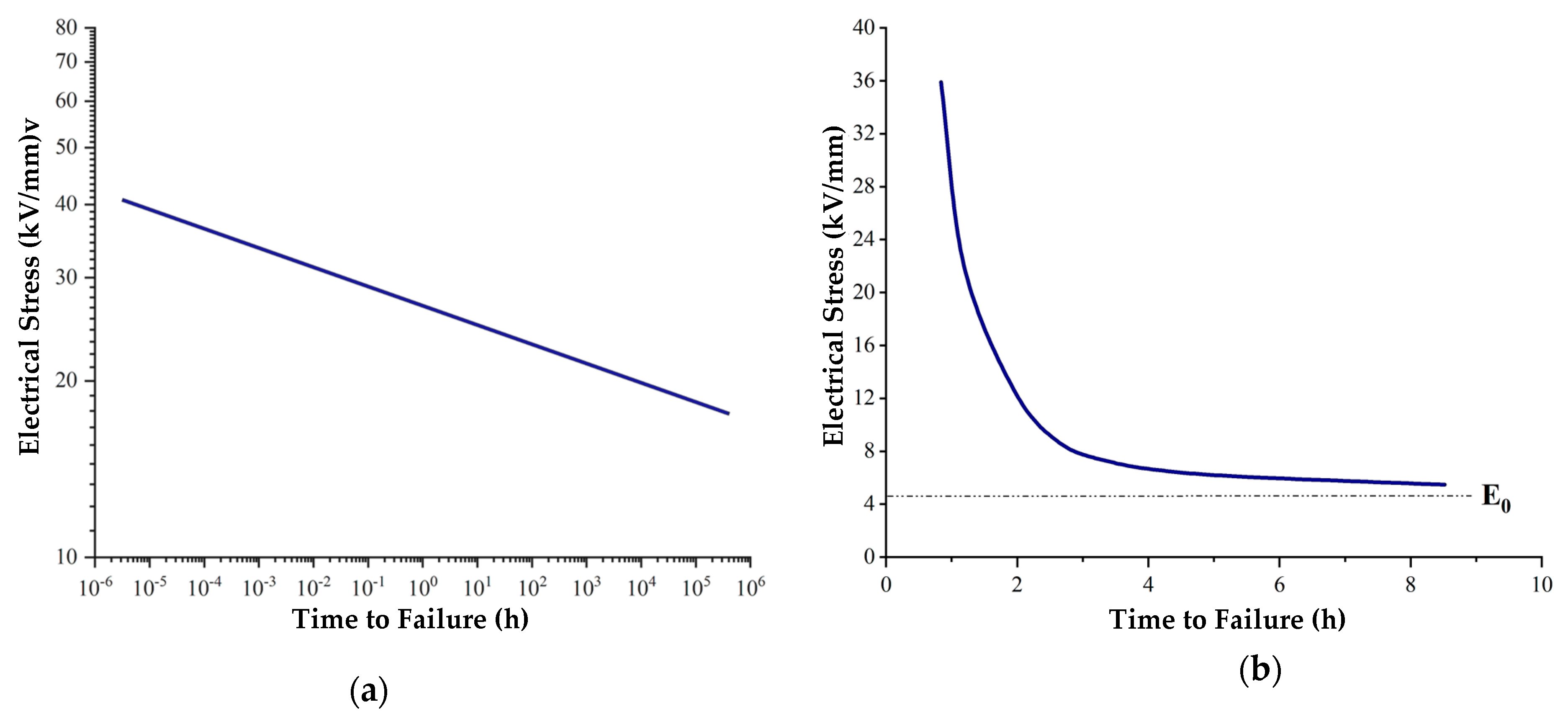
4.2. Electric Stress Lifetime Modelling

In LV EM employing Type I insulation, the electrical stress is not considered a source of aging [97] but affects the end-of-life of the EIS. Differently, the aging caused by electrical stress is typical of Type II insulation. Electrical stress aging is commonly modeled via two lifetime models: the inverse power law model (IPM) and the exponential law model (ELM) [98]. In Figure 9, the relationship between the lifetime and electrical stress level is illustrated: (a) is in the form of a log–log graph for IPM, and (b) is plotted in a normal coordinate system for ELM. The lifetime model based on the inverse power law is expressed as in (10):
L e = c G n
where Le is the failure time, G is the applied electrical stress, and c and n are constants.
The lifetime model ruled by the exponential law is given in (11):
L e = k e ( h G )
where the constants k and h are constants.
The constants c and k are the model parameters whose specific value is determined by the electrical lifetime test results. The parameters n and h represent the voltage-endurance coefficient (VEC), which is the slope of the life graph between the applied electrical stress and the lifetime. The higher VEC value represents the stronger resistant to electrical stress of insulation material.
Equation (11) represents a straight line with slope h on semi-log paper (i.e., log(L) vs. G). The lifetime graph associated with the ELM gradually approaches the electrical threshold E0, and when the field strength is lower than E0, the electrical stress does not induce aging. The initial expressions of Equations (10) and (11) have been modified by introducing a threshold parameter G 0 [99], and their refined form is reported in (12) and (13).
Figure 9. Electrical stress vs. insulation lifetime: (a) IPM graph (logarithmic plot) and (b) ELM graph (semi-log plot) [100].
Energies 17 01987 g009
L e = L t ( G G 0 G t G 0 ) n
L e = L t e ( h ( G G 0 ) ( G G 0 ) / ( G t G 0 )
where Lt indicates the electrical aging life of insulation materials under the electrical stress Gt, and G0 is the threshold electric field strength, which depends on the considered material.
Both lifetime model types are obtained from empirical data. However, IPM Equation (10) is consistent with Weibull statistics, and it is frequently applied in pure electrical stress situations, and it is widely used for extruded cable insulation [100]. On the contrary, the ELM is suitable for modeling combined thermo-electrical stress [98]. In [101,102], the IPM is adopted to evaluate the impact of voltage amplitude and frequency on the EM lifetime. In [12,103], the IPM is applied to extrapolate the electrical lifetime at nominal voltage.

4.3. Lifetime Modelling under Thermo-Electrical Stress

In actual operating conditions, the EIS is exposed to combined stresses, and the thermal lifetime model based on chemical reaction rate theory is modified to account for the electrical stress contribution to the aging process. The oxidation process of polymer materials is still considered the primary aging factor ruled by thermal stress, while electric stress affects the oxidation process parameters (i.e., reaction rate, etc.). Therefore, three thermo-electrical lifetime models are developed, namely Simoni’s, Fallou’s, and Ramu’s [97,98].

4.3.1. Simoni’s Model

In 1981, Simoni proposed a thermo-electrical aging model according to the formulation shown in (14).
R = A e ( B T ) e [ ( a + b T ) f ( G ) ]
where f(G) is the function of the electric field; A, B, a, b are all constants, which are obtained by experiments performed on the EIS. For f(G), two forms are considered according to the IPM and ELM electrical stress model [98]. One is based on inverse power law f(G) = ln(G/G0), whereas the other is based on exponential law f(G) = GG0. To obtain the thermo-electrical lifetime model, it is necessary to define the aging rate that corresponds to the aging amount F. The function of F is dependent on a parameter p that characterizes the insulating properties of the material. For insulation polymer material, the aging amount F corresponds to the change in the degree of polymerization, which is represented by ΔDP. Meanwhile, R represents the rate of decrease in the degree of polymerization, which could be expressed as R = d(DP)/dt. Under constant electrical and thermal stresses, the aging rate R is approximated as a constant; therefore, the relationship between F and R becomes as in (15).
F ( p ) = R t
When p reaches the critical value pL, the insulation fails, and the aging time t is equal to lifetime L. Therefore, by substituting Equation (14) into (15), the thermo-electrical lifetime model equation is obtained (16).
L ( T , G ) = L 0 e B Δ T e ( n b Δ T ) f ( G )     where     a + b T 0 = n
where L(T, G) is the multi-stress lifetime; L0 is the lifetime when the electrical stress is G0.

4.3.2. Fallou’s Model

Based on the combined thermo-electrical aging tests and single-factor aging theory, Fallou proposed a semi-empirical model (17) in 1979 [104]. In this model, the threshold value G0 of electrical stress was not considered, implying that any G greater than 0 was regarded as having an impact on the insulation lifetime.
L = e ( A F + B F T ) ,   E > 0
In (17), AF = A1 + A2G; BF = B1 + B2G, where A1, A2, B1, and B2 are all constants, which means the AF I and BF parameters are changed with electrical stress G. By expressing the terms AF into (17), Equation (18) is derived.
L ( T , G ) = e ( A 1 + B 1 T ) e ( ( A 2 + B 2 T ) G )
Fallou’s model application is restricted to the exponential law electrical stress lifetime model, and the experimental results at room temperature do not align with those delivered by the model.

4.3.3. Ramu’s Model

In 1985, Ramu proposed a thermo-electrical aging model (19) based on the classical single-factor aging model [105]. The temperature variation is regarded as a factor that could affect the constant in the electrical aging inverse power law model.
L ( T , G ) = K ( T ) G n ( T ) e ( B   D T ) G > G 0
where
K ( T ) = e ( K 1 K 2 D T ) ,   and   n ( T ) = n 1 n 2 D T
K1, K2, n1, n2 are all constants which are obtained via experimental tests. In the case where the threshold G0 is integrated in Equation (19) and the electrical field E, temperature T, and aging time L are maintained at their reference values of E0, T0, and L0, the function n(T) can be eliminated. In this scenario, Ramu’s model is equivalent to Simoni’s one.
To summarize, thermal aging is triggered by an oxidative decomposition, which is modeled using chemical reaction rate theory (1). Under sole thermal stress, the time required for the material’s properties to degrade to a certain level is established based on the chemical reaction/kinetic equation. On the other hand, the impact of electrical stress on the performance of insulation is modeled as a probabilistic distribution (i.e., stochastic distribution) [98,106,107].

4.4. Lifetime Modelling under Thermo-Electrical Stress

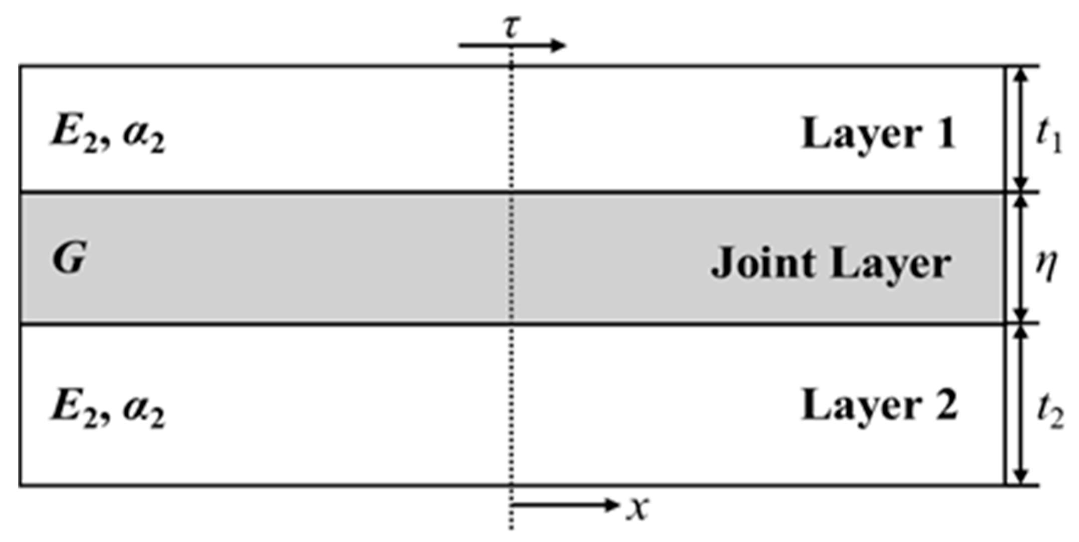
4.4.1. Thermal-Induced Mechanical Stress Model

As described in Section 3.4, the thermo-mechanical stress is generated from the inside structure of EIS, which makes it hard to place a sensor to detect the inside deformation. However, the existence of internal mechanical stress is verified through numerical simulations [31,89,108].
The finite element analysis (FEA) on internal mechanical stress is conducted in [89]. As shown in Figure 10, the enameled magnet wire layout is simplified to three symmetric layers, where the wire structure consisting of a copper layer (i.e., layer 1), a coating layer (i.e., joint layer), and an epoxy layer (i.e., as layer 2). As an outcome of the study, the internal thermal-induced mechanical stress is modeled via the analytical equations in (21) and (22).
τ = ( α 1 α 2 ) G Δ T sinh ( β x ) β η cosh ( β l )
β 2 = G η ( 1 E 1 t 1 + 1 E 2 t 2 )
The physical parameters in (21) and (22) hold the following meaning and unit: τ represents the shear stress in Pascal (Pa), α denotes the TEC in parts per million per degree Celsius (ppm/°C), E is the elastic moduli of the top and bottom layers, G signifies the shear modulus of the joint layer, L represents the length in the x-direction, while t1 and t2 are the thicknesses of top and bottom layers. The peak shear stress τmax (23) at the extremity of the bonded layers is independent of the total length l, and it is derived from (21) assuming tanh(βl) ≈ 1.
τ max = ( α 1 α 2 ) G Δ T tanh ( β l ) β η ( α 1 α 2 ) G Δ T β η
In [31], the lifetime loss due to pure thermal stress aging and thermo-mechanical stress aging are separated. The cycling temperature experiments are performed, and based on the experiment results, the difference between the peak temperature and the lowest temperature has an impact on insulation aging. In particular, a higher difference leads to a quicker aging rate.
The damage derived from the thermal-induced mechanical stress resulting from periodic temperature profiles is regarded as material fatigue. Thus, the cumulative failure law, i.e., the Miner’s Law, is employed assuming Ni as the number of cycles to failure at the i-th stress level for a specific material. If the material undergoes a number of cycles ni at the stress i-th level, then the ratio ni/Ni represents the cumulative damage fraction consumed by the i-th stress level. The sum of mechanical damage fractions M across all stress levels is calculated by (24).
M = i n i N i
Then, the refined multi-stress loss of life fraction (LFTM) is expressed in (25).
L F T M 1 = 1 L 0 e B ( 1 θ ( t ) 1 θ 0 ) d t + i , j N c y c l e s ( Δ θ i , θ p e a k j ) N i , j %
Finally, the total lifetime is determined according to (25), which features a similar structure as (9).
L t o t = Δ t c y c l e L F T M 1
The first term in (25) is referred to as the thermal factor term, whereas the second term reveals an increment in loss of life due to the cyclic mechanical stress induced by thermal expansion. Ni,j represents the number of cycles that experience a temperature swing of Δθi and a peak temperature of θpeakj; the data are obtained by a counting algorithm (such as the rain-flow counting method). In general, Equation (25) expresses the thermal-mechanical lifetime loss fraction, while the total lifetime is calculated by (26). Finally, the specific calculation of mechanical stress magnitude can be obtained by combining Equations (23) and (24).

4.4.2. Thermal-Induced Mechanical Stress Model

In [32], the constant thermo-mechanical stress in EM insulation is related to the rate of temperature change over time, denoted as v. The insulation lifetime under mechanical stress (27) is modeled using an inverse power law equation, where LM represents the lifetime and k and N are parameters determined through accelerated aging tests.
L M ( v ) = ( 1 + k | v | ) N
In (27), mechanical stress is considered a secondary influential factor akin to the thermal-electrical model previously discussed. Specifically, the mechanical stress is presumed to be associated with v and subsequently incorporated into the thermal model, LT, through a corrective term. Consequently, the thermal-mechanical model is expressed as an equation that incorporates temperature and the rate of temperature change, yielding to (28).
L T M ( T , v ) = L T ( T ) L M ( v ) G ( T , v )
The corrective term G in (28) has the form expressed in (29).
G ( T , v ) = ( 1 + k | v | ) N ( B T B T 0 )
Same as the lifetime fraction in previous sections, the LFTM is calculated as in (30).
L F T M 2 = t 0 t f 1 L ( T ( t ) , v ( t ) ) d t
Then, the total lifetime could be determined by (31).
L t o t = Δ t c y c l e L F T M 2
In Equation (27), the parameters N and k are derived through accelerated aging tests. The developed thermal-induces mechanical stresses model relies on the precondition of incorporating the mechanical term modification, as proposed in [109], where both mechanical and electrical stresses are accounted for in the thermal model by introducing the corresponding modification terms.

4.5. Summary of Insulation Lifetime Models

The lifetime models can be grouped into three main categories: phenomenological, physical, and stochastic [110], as shown in Figure 11.
Phenomenological models are empirical models obtained by fitting experimental data, and they are regarded as a mathematical representation that connects the winding failure time to the suffered stresses. On the other hand, physical lifetime models aim to capture the underlying physical processes and internal mechanisms that govern the degradation and failure of materials or components. They strive to establish cause-and-effect relationships between suffered stresses and the changing of material properties (microstructure layer). In stochastic models, the insulation failure is expressed as a probability that increases with the stresses aging. For example, models in (2), (9), and (14) are more phenomenological ones, while models in (22) and (25) are physical ones; and finally, the model in (10) is mainly a stochastic one.

5. Accelerate Lifetime Tests

Collecting lifetime data under normal operating conditions is time-consuming, costly, and, in some cases, impracticable. As a consequence, electrical insulation design engineers and material scientists have devised methodologies to expedite the aging process by applying abnormal stresses that accelerate insulation deterioration. The data collected under abnormal operating conditions are then used to extrapolate the EIS lifetime at normal conditions. In this Section, procedures and specimens considered in thermal ALTs at constant and periodic temperatures are discussed, as well as in electrical endurance tests.

5.1. Thermal ALT at Constant Temperature

Thermal ALTs at constant temperature are performed at least at three temperature values in order to meet the extrapolation function. The selection of the three temperature values is constrained by the glass transition temperature (e.g., 290 °C for polyamide-imide enameled wire), which leads to a secondary reaction that compromises the recorded results [111]. Therefore, the highest thermal ALT temperature needs to be lower than the glass transition temperature. On the other hand, the lowest thermal ALT temperature must be higher than the insulation thermal class. The test procedure, specimens and diagnostic session are regulated by technical standards [23,112,113,114].

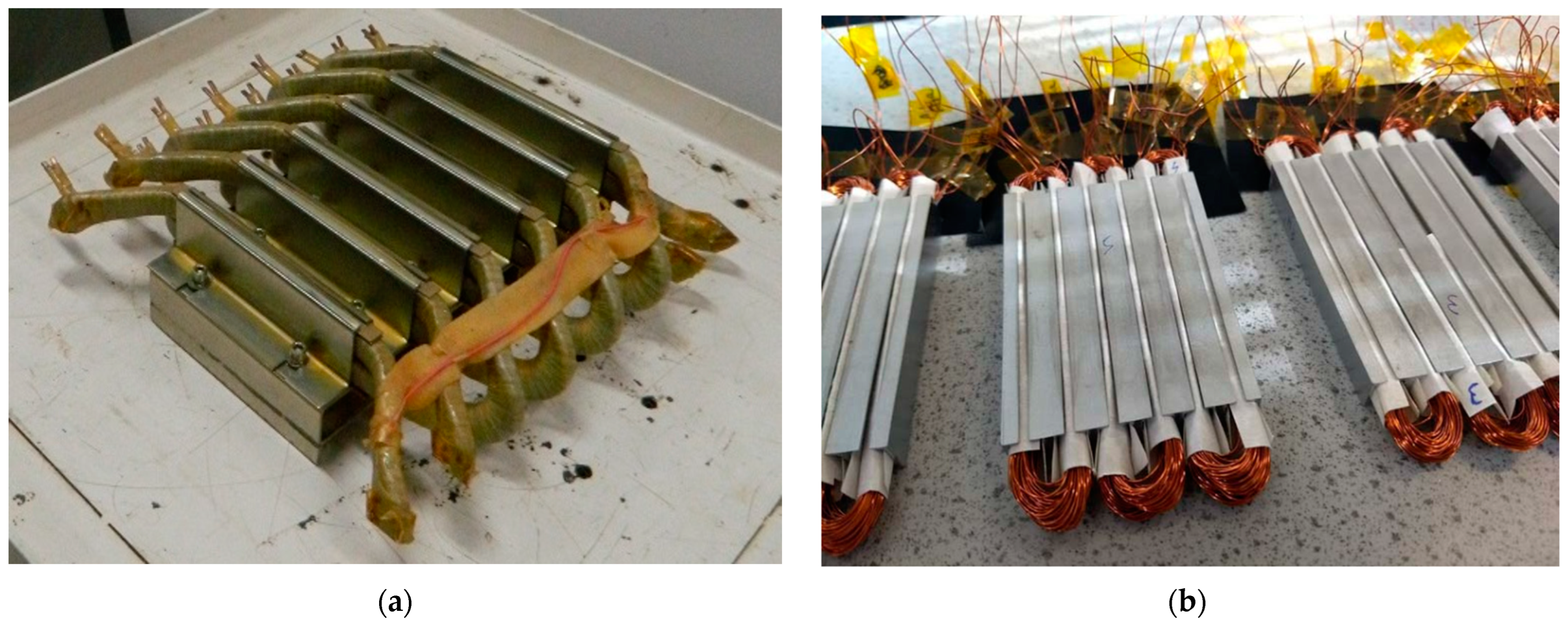
5.1.1. Experimental Setup

The experiment platforms for thermal ALTs at constant temperature are relatively simple, the crucial component is the ventilated oven, which is required to reach a high precision and an even temperature distribution [6,25]. The ventilated performance and structure are important to keep the samples’ temperature consistent in the oven. However, a small temperature difference (±3 °C) is unavoidable, and the data post-processing will cover the deviation. According to the standard IEC 60505 [80], apart from pure thermal stress aging, external mechanical aging could be combined to achieve the stress synergies effect. In [21], the vibration shaker system is used to impose mechanical stress on the samples, which are located in a ventilated oven for simultaneous thermal exposure. This synergies effect is achieved using a bar plugged into the oven that transfers the vibration produced by the shaker; the experimental platform schematic is shown in Figure 12. Then, the specimens (coupled bars) are stuck on the beam and simultaneously suffer from the thermal stress from the oven.

5.1.2. Specimens’ Choice

As depicted in Figure 13, the specimens’ topologies employed in ALT are various, ranging from complex to simple, which encompasses the entire motor, stator winding, motorettes (b)/formettes (a) (i.e., segment stator/rotor), coils and twist pairs. In [115], three kinds of specimens are aged at three constant temperatures (250 °C, 270 °C, 290 °C), and the Weibull probability density plot is given to evaluate the failure time. Technical standards [14,114] prescribe the use of whole EMs as samples, but this choice might be very expensive and time-consuming due to the manufacturing time. For these reasons, motorettes are also recommended, and they are the most frequently used sample in thermal ALTs because they enable a good trade-off between cost and mirroring of the actual EIS laying condition. The sample’s winding consists of two parallel strands, for evaluating the inter-turn dielectric properties.

5.1.3. Diagnostic Session

The diagnostic session would be conducted every 24/48 h according to related regulation suggestions and the temperature index of magnet wires [114], which could also be called the AC hi-pot test [14]. It is usually executed through the dissipation factor tester (i.e., Megger® Delta 4000). In this evaluation, a 500 Vrms sinusoidal voltage with a frequency of 50 Hz is applied for a duration of one minute across parallel terminals within the same coil. Then, the diagnostic voltage amplitude is intentionally set at the PDIV value of the magnet wire for the purpose of obtaining a more conservatively estimated lifetime. The criterion for determining the end of the coil’s operational life is predicated on the occurrence of dielectric breakdown. Once the coil can no longer withstand the diagnostic voltage, it is considered to have reached its ‘death’, and the end-of-life is identified as happening in the middle of the last exposure. As a result, the failure time is equal to adding the total duration of thermal exposure and subtracting half of the thermal cycle period. Subsequent to the diagnostic session, all alive coils continue to carry the accelerating test until all test specimens reach failure in the final thermal exposure.

5.2. Thermal ALT at Variable Temperature

Thermal ALT at variable temperatures consists of cyclically applying a predefined temperature profile to the specimens. Since no specific technical standard regulates the test procedure, common sense is recommended during the design of the experiment. However, the diagnostic session is totally the same as constant aging ALTs.

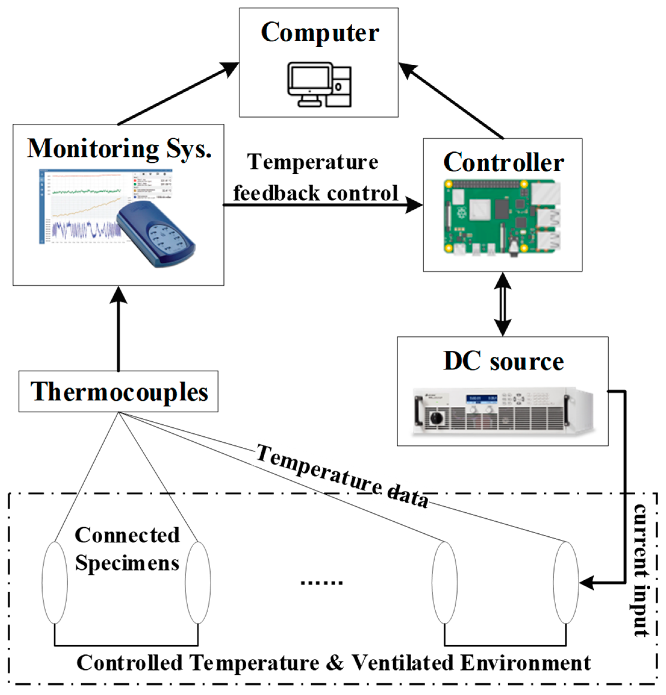
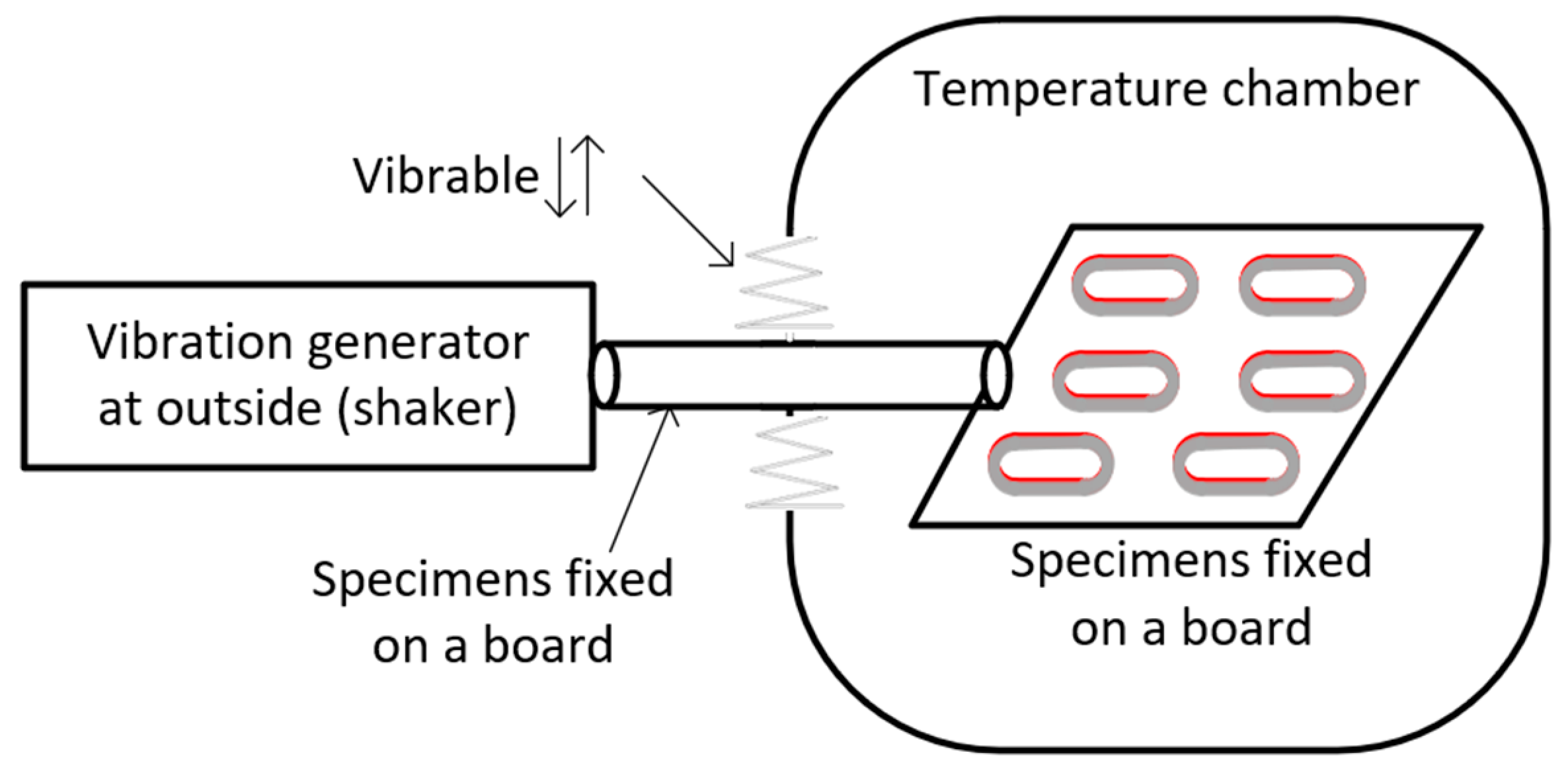
5.2.1. Experimental Setup

In order to generate the periodic temperature profile and be sure that the temperature applied to the specimens follows the desired trend, a temperature control system is implemented, as schematically illustrated in Figure 14. The computer serves as the central hub for interconnecting various components and monitoring/recording information. The controller is equipped with programs for transferring the signal to the DC source, which can make current input increase or decrease. At the same time, the controller is also receiving the real-time temperature data to achieve the feedback control system. Finally, the coils are connected to each other in series or parallel and placed in an ambient chamber.
In [108], the specimens’ temperatures are not directly measured via thermal sensors, but they are obtained through real-time resistance measurements exploiting the relationship in (32).
R ( T ) = R 0 [ 1 + α ( T T 0 ) ]
In [20], the temperatures are directly measured using thermocouples, and the specimens are hung to a PTFE rod and inserted into a fume, as reported in Figure 15.
In [89], water-cooled motorettes are used as test samples, which are shown in Figure 16, and both the water flowing rate and DC current are controlled to match the desired temperature profile. Similarly, air-cooled motorettes are thermally aged in [117], and the corresponding test bench is shown in Figure 17.
Challenges of thermal ALTs at variable temperatures are represented by the controller tuning [118] and the delay in the temperature feedback. These aspects result in changes in the applied temperature profiles making difficult the results comparison.

5.2.2. Specimens’ Choice

The samples used in thermal ALTs at variable temperatures are generally similar to those for constant-temperature thermal aging. However, due to the temperature fluctuations, ensuring accurate temperature measurements is challenging and the thermal sensor location becomes crucial. Sometimes thermal model or FEA of the sample under test is developed to precisely identify the exact winding hot-spot location and consequently install the thermal sensors [108,118]. An example of a motorette and associated lumped parameter thermal network is depicted in Figure 18.
In some other cases, multiple thermal sensors embedded inside the motorette are also used, and by post-processing the recorded temperature profiles, the effect of the temperature fluctuations is mitigated, as in [117,118,119].
Although the coils are not specimens prescribed by technical standards, experimental studies carried out on coils revealed a more balanced temperature distribution [20], and compared to specimens, such as motorettes and twisted pairs, coils exhibit a shorter lifetime [115], which makes them more prone to deliver conservative lifetime predictions. As for the twist pair specimens, the structure features nearly no heat capacity, making them unsuitable for thermal ALTs at variable temperatures.

5.3. Electrical Endurance and PD Tests

Electrical aging tests are less time-consuming than thermal aging tests, and parameters, such as amplitude, raising time, and frequency of the applied voltage, are varied to evaluate their impact on the EIS lifetime. As recommended by IEC 60034-27-5 [120], PD measurements are performed on the insulation status during the diagnostic session that follows the stress application (thermal or electrical).

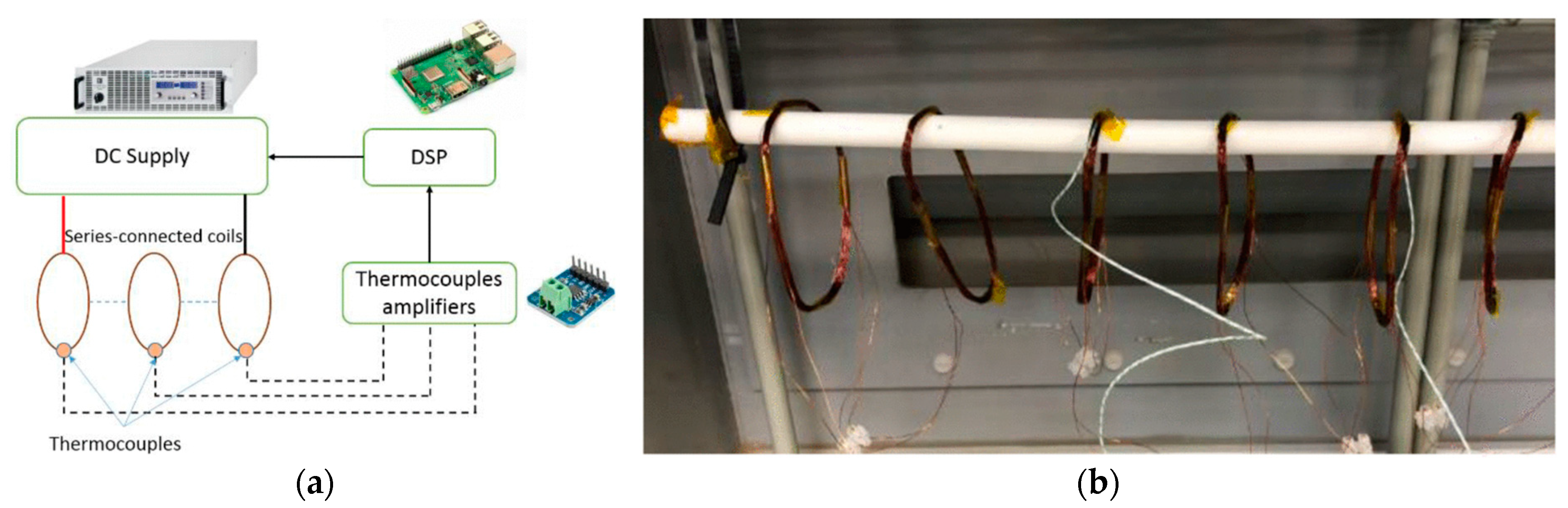
5.3.1. Experimental Platform Setup for Electrical Aging

The platform for the PD measurements is depicted in Figure 19, where the PD is detected using a photomultiplier tube (PMT), which is immune to electromagnetic noise. Apart from the PMT, an ultrahigh-frequency sensor can be adopted as a PD detector. Since the PD signal can reach a frequency of up to 1.5 GHz, while the switching noise is mainly located between 0 and 400 MHz, a 500 MHz high-pass filter is often used to eliminate the switching noise.
The HV pulser is powered by an HV DC supply, and its output is regulated by a signal generator. In this way, the unipolar square waveform voltage with controllable pulse width is transferred to the specimens and the rise time of the excitation voltage could be adjusted by regulating the load impedance. The specimens can be placed in the chamber for controlling temperature and pressure during the PD measurements. Finally, a scope is used for monitoring and recording the PD inception signal.

5.3.2. Specimens’ Choice

Following the recommendation of the standard IEC 60851-5 [112], twist pair is the most common specimen in electrical aging tests, and examples of twisted pairs are illustrated in Figure 20. The specimens are usually preconditioned before starting the test to remove impurities, and the preconditioning is accomplished by a thermal exposure at 120 °C for 1 h. In some cases, the electrical endurance tests are performed on impregnated twist pairs [11].

6. Reliability Oriented Design and Remaining Useful Life

Based on the post-processing of ALT data, the parameters required to characterize the lifetime model are determined [25,122], and the tuned lifetime model can be either used for predicting the remaining useful lifetime (RUL) of an in-service EMs or for estimating the time-to-failure of EMs under design with the purpose of meeting the reliability constraint and implement the reliability-oriented design (RoD). These two approaches must characterize the EIS evolution from the early design stage, where RoD is implemented to support the insulation design, to the in-service operations, where RUL is adopted for monitoring the EIS health condition and scheduling maintenance actions. In Figure 21, the integration and the synergy between RUL and RoD strategies are schematically highlighted.
In RUL prediction, real-time monitoring techniques are used to acquire specific diagnostic markers from the EIS. These diagnostic markers define the EIS health status, and the RUL is determined relying on the lifetime model. If the estimated RUL is below a certain threshold, an early warning is issued before the EIS failure occurs and maintenance or replacement is properly scheduled. On the other hand, RoD is used at the EM design stage to verify the fulfillment of the reliability requirements. In fact, the lifetime model is used to forecast the time-to-failure of an EM under design, and if the reliability level required by the application at hand is not met, the insulation design, as well as the EM design can be accordingly revised. The flowchart of the RoD methodology is given in Figure 22.
Although the RoD enables the achievement of the reliability constraints, the ultimate prototype must undergo thorough qualification before attaining market readiness. However, a continual exploration of the dielectric domain empowers EM designers to evaluate reliability during the design phase, moving beyond the insulation over-engineering. In summary, EM reliability is a target that contains many fields that are interconnected with each other, and the main aspects are shown in Figure 23. The fundamental objectives consist of meeting the design requirements while ensuring an adequate reliability level for obtaining technical standards certification. Simultaneously, monitoring and maintenance are good practice methodologies that allow to ensure the EM operativity and minimize the downtimes. Finally, the degradation rules and PoF research provide the essential tools for enabling an EM design that accounts for reliability since the early-stage design promotes the paradigm shift from performance-oriented design to RoD.

7. Conclusions and Future Perspectives

High-performance and reliable EMs are demanded in transportation electrification, and the winding EIS partially represents a reliability bottleneck. However, the understanding of EIS failure and EM reliability is relatively limited compared to the advancements in EM performance. Therefore, the PoF analysis of winding EIS represents a crucial research area in the field of EM reliability. For this reason, a compressive review of EIS for EMs was presented considering winding technology, EIS stressing factors, lifetime modeling, and prediction and monitoring of insulation health conditions. Knowledge of the aging process and methodologies for accurate lifetime estimation are relevant aspects for ensuring EMs’ safe operations and achieving better exploitation of insulating materials.
A variety of lifetime models are available in the literature, ranging from single-stress lifetime models to multi-stress ones. The formers are easy to develop and tune, but their applicability is limited to specific circumstances and/or applications since a prevailing aging factor is assumed, while in reality, the EIS is exposed to several degradation factors. Multi-stress lifetime models include the influence of two or more aging factors, but multiple parameters are required for achieving a good fitting quality of experimental data. Hence, the development of lifetime model research should be a trade-off to identify more optimal directions for lifetime predictions. Furthermore, the design of ALT platforms is also a considerable aspect of enhancing the research on lifetime prediction. Although the choice of the lifetime model might result in challenges and its tuning might be time-consuming due to the necessity of performing ALTs, their employment at the design stage (RoD) and during the EM service (RUL) promotes safe operations, improves the design of insulation and minimize downtime. Based on the deep research of PoF of insulation, then combining RoD and RUL methodologies, the EIS undergoes a thorough development process that ensures the reliability standard via an appropriate design of insulation and enables its condition monitoring during the service life.
Many fields, from dielectric material science to health monitoring condition strategies passing through innovative thermal management methodologies, contribute and cooperate to accomplish a more reliable EM design. While in-depth research in each field is necessary, it is equally important to establish bridges between them in order to move from a component to a system perspective. In the future, when a more profound understanding of windings’ PoF is reached, and a larger set of data collected on in-service EMs is available, machine learning and artificial intelligence might be employed for developing more comprehensive and accurate lifetime models for assessing and predicting EM reliability.

Funding

This work was supported by the Ningbo Natural Science Foundation under Grant 2023J192.

Data Availability Statement

The article information collected in this review is data available publicly accessible repositories: IEEE Xplore (https://ieeexplore.ieee.org/Xplore/home.jsp); Scopus (https://www.scopus.com); and were accessed on 15 April 2024.

Conflicts of Interest

The authors declare no conflict of interest.

Abbreviation

AEAAll Electric Aircraft
ALTAccelerated Lifetime Test
EMElectric Machine
EVElectric Vehicle
EISElectric Insulation System
ELMExponential Law Model
eVTOLelectrical Vertical Take-Off and Landing aircraft
FEAFinite Element Analysis
HVHigh Voltage
IECInternational Electrotechnical Commission
IPMInverse Power Law Model
LVLow Voltage
MEAMore Electric Aircraft
OFOvervoltage Factor
PAIPolyamideimide
PDPartial Discharge
PDIVPartial Discharge Inception Voltage
PEIPolyetherimide
PMTPhotomultiplier Tube
PoFPhysics of Failure
RoDReliability-oriented Design
PWMPulse Width Modulation
RULRemaining Useful Life
TEAMThermal, Electrical, Ambient, Mechanical
TgTransition to Glass
TPTemperature Profile
TECThermal Expansion Coefficient
VECVoltage-Endurance Coefficient
VSDVariable Speed Drive
WBGWide Bandgap

References

  1. Swaminathan, N.; Reddy, S.R.P.; Rajashekara, K.; Haran, K.S. Flying Cars and eVTOLs—Technology Advancements, Powertrain Architectures, and Design. IEEE Trans. Transp. Electrif. 2022, 8, 4105–4117. [Google Scholar] [CrossRef]
  2. European Comission. Annual Analyses of the EU Air Transport Market; European Comission: Brussels, Belgium, 2016. [Google Scholar]
  3. IEA. Global EV Outlook 2021—Accelerating Ambitions Despite the Pandemic; Technical Report; IEA: Paris, France, 2021; p. 101. [Google Scholar]
  4. El-Refaie, A.; Osama, M. High Specific Power Electrical Machines: A System Perspective. CES Trans. Electr. Mach. Syst. 2019, 3, 88–93. [Google Scholar] [CrossRef]
  5. Galea, M.; Giangrande, P.; Madonna, V.; Buticchi, G. Reliability-Oriented Design of Electrical Machines: The Design Process for Machines’ Insulation Systems MUST Evolve. IEEE Ind. Electron. Mag. 2020, 14, 20–28. [Google Scholar] [CrossRef]
  6. Han, C. Lifetime evaluation of class e electrical insulation for small induction motors. IEEE Electr. Insul. Mag. 2011, 27, 14–19. [Google Scholar] [CrossRef]
  7. Yang, D.; Liu, X. Remaining Useful Life Prediction for bearing based on Online Oil Parameters and Vibration Signals. In Proceedings of the 2022 Global Reliability and Prognostics and Health Management (PHM-Yantai), Yantai, China, 13–16 October 2022; pp. 1–5. [Google Scholar] [CrossRef]
  8. Liu, Q.; Ma, G.; Cheng, C. Generative Adversarial Network Based Multi-class Imbalanced Fault Diagnosis of Rolling Bearing. In Proceedings of the 2019 4th International Conference on System Reliability and Safety (ICSRS), Rome, Italy, 20–22 November 2019; pp. 318–324. [Google Scholar] [CrossRef]
  9. Albrecht, P.; Appiarius, J.; Sharma, D. Assessment of the Reliability of Motors in Utility Applications—Updated. IEEE Trans. Energy Convers. 1986, EC-1, 39–46. [Google Scholar]
  10. He, J.; Somogyi, C.; Strandt, A.; Demerdash, N.A.O. Diagnosis of stator winding short-circuit faults in an interior permanent magnet synchronous machine. In Proceedings of the 2014 IEEE Energy Conversion Congress and Exposition (ECCE), Pittsburgh, PA, USA, 14–18 September 2014; pp. 3125–3130. [Google Scholar] [CrossRef]
  11. Ji, Y.; Giangrande, P.; Zhao, W.; Madonna, V.; Zhang, H.; Galea, M. Derivation of Ambient Enhancement Factors of Impregnated Twisted pairs for Partial Discharge Risk Evaluation. IEEE Trans. Transp. Electrif. 2023, 10, 485–495. [Google Scholar] [CrossRef]
  12. Ji, Y.; Giangrande, P.; Wang, H.; Zhao, W.; Madonna, V.; Zhang, H.; Galea, M. Time-to-failure analysis of short-duty cycle, inverter-fed electrical machines exposed to prevailing electrical stress. IEEE Trans. Aerosp. Electron. Syst. 2023, 59, 9368–9378. [Google Scholar] [CrossRef]
  13. Ji, Y.; Giangrande, P.; Zhao, H.; Zhao, W.; Madonna, V.; Zhang, H.; Galea, M. Electrical Machine Design Considering Corona-Resistant Wire for More Electric Aircraft Applications. IEEE Trans. Transp. Electrif. 2023, 9, 3192–3202. [Google Scholar] [CrossRef]
  14. IEC 60034-18-41:2014; IEC 60034 Rotating Electrical Machines—Part 18–41: Partial Discharge Free Electrical Insulation Systems (Type I) Used in Rotating Electrical Machines Fed from Voltage Converters—Qualification and Quality Control Tests. International Electrotechnical Commission: London, UK, 2014.
  15. MI-HDBK-217F; Reliability Prediction of Electronic Equipment. Department Defence, United States of America: Washington, DC, USA, 1991.
  16. Wang, H.; Liserre, M.; Blaabjerg, F.; Rimmen, P.d.P.; Jacobsen, J.B.; Kvisgaard, T.; Landkildehus, J. Transitioning to physics-of-failure as a reliability driver in power electronics. IEEE J. Emerg. Sel. Top. Power Electron. 2014, 2, 97–114. [Google Scholar] [CrossRef]
  17. Madonna, V.; Giangrande, P.; Galea, M. Introducing physics of failure considerations in the electrical machines design. In Proceedings of the 2019 IEEE International Electric Machines & Drives Conference (IEMDC), San Diego, CA, USA, 12–15 May 2019; pp. 2233–2238. [Google Scholar] [CrossRef]
  18. Lee, S.B.; Kang, T.J.; Kim, H.; Kong, T.; Lim, C. Case studies of stator winding turn insulation failures in medium voltage motors. In Proceedings of the 2017 Annual Pulp, Paper and Forest Industries Technical Conference (PPFIC), Tacoma, WA, USA, 18–23 June 2017; pp. 1–8. [Google Scholar] [CrossRef]
  19. Cheng, C.; Ma, G.; Zhang, Y.; Sun, M.; Teng, F.; Ding, H.; Yuan, Y. A Deep Learning-Based Remaining Useful Life Prediction Approach for Bearings. IEEE/ASME Trans. Mechatron. 2020, 25, 1243–1254. [Google Scholar] [CrossRef]
  20. Madonna, V.; Giangrande, P.; Lusuardi, L.; Cavallini, A.; Gerada, C.; Galea, M. Thermal Overload and Insulation Aging of Short Duty Cycle, Aerospace Motors. IEEE Trans. Ind. Electron. 2020, 67, 2618–2629. [Google Scholar] [CrossRef]
  21. Mancinelli, P.; Stagnitta, S.; Cavallini, A. Qualification of Hairpin Motors Insulation for Automotive Applications. IEEE Trans. Ind. Appl. 2017, 53, 3110–3118. [Google Scholar] [CrossRef]
  22. Ghassemi, M. Accelerated insulation aging due to fast, repetitive voltages: A review identifying challenges and future research needs. IEEE Trans. Dielectr. Electr. Insul. 2019, 26, 1558–1568. [Google Scholar] [CrossRef]
  23. IEC 60172-2020; Test Procedure for the Determination of the Temperature Index of Enamelled and Tape Wrapped Winding Wires. International Electrotechnical Commission: London, UK, 2015.
  24. IEC 60034-18-42:2017; IEC 60034: Rotating Electrical Machines—Part 18–42: Partial Discharge Resistant Electrical Insulation Systems (Type II) Tests Used in Rotating Electrical Machines Fed from Voltage Converters-Qualification. International Electrotechnical Commission: Geneva, Switzerland, 2017.
  25. Giangrande, P.; Madonna, V.; Nuzzo, S.; Galea, M. Moving toward a Reliability-Oriented Design Approach of Low-Voltage Electrical Machines by Including Insulation Thermal Aging Considerations. IEEE Trans. Transp. Electrif. 2020, 6, 16–27. [Google Scholar] [CrossRef]
  26. Kokko, V.I.J. Ageing due to thermal cycling by start and stop cycles in lifetime estimation of hydroelectric generator stator windings. In Proceedings of the 2011 IEEE International Electric Machines & Drives Conference (IEMDC), Niagara Falls, ON, Canada, 15–18 May 2011; pp. 318–323. [Google Scholar] [CrossRef]
  27. Rothe, R.; Hameyer, K. Life expectancy calculation for electric vehicle traction motors regarding dynamic temperature and driving cycles. In Proceedings of the 2011 IEEE International Electric Machines & Drives Conference (IEMDC), Niagara Falls, ON, Canada, 5–18 May 2011; pp. 1306–1309. [Google Scholar] [CrossRef]
  28. Mitsui, H.; Inoue, Y.; Kenjo, S.; Corporation, T. Thermal Cyclic Degradation of Coil Insulation for Rotating Machines. IEEE Trans. Power Appar. Syst. 1983, PAS-102, 67–73. [Google Scholar] [CrossRef]
  29. Huang, Z.; Reinap, A.; Alaküla, M. Degradation and fatigue of epoxy impregnated traction motors due to thermal and thermal induced mechanical stress—Part I: Thermal mechanical simulation of single wire due to evenly distributed temperature. In Proceedings of the 8th IET International Conference on Power Electronics, Machines and Drives (PEMD 2016), Glasgow, UK, 19–21 April 2016; pp. 1–6. [Google Scholar] [CrossRef]
  30. Huang, Z.; Reinap, A.; Alaküla, M. Degradation and fatigue of epoxy impregnated traction motors due to thermal and thermal induced mechanical stress—Part II: Thermal mechanical simulation of multiple wires due to evenly and unevenly distributed temperature. IET Conf. Publ. 2016, 2016, 1–5. [Google Scholar] [CrossRef]
  31. Griffo, A.; Tsyokhla, I.; Wang, J. Lifetime of machines undergoing thermal cycling stress. In Proceedings of the 2019 IEEE Energy Conversion Congress and Exposition (ECCE), Baltimore, MD, USA, 29 September–3 October 2019; pp. 3831–3836. [Google Scholar] [CrossRef]
  32. Sciascera, C.; Galea, M.; Giangrande, P.; Gerada, C. Lifetime consumption and degradation analysis of the winding insulation of electrical machines. IET Conf. Publ. 2016, 2016, 1–5. [Google Scholar] [CrossRef]
  33. Mikami, H.; Ide, K.; Shimizu, Y.; Senoo, M.; Seki, H. Historical evolution of motor technology. Hitachi Rev. 2011, 60, 38–45. [Google Scholar]
  34. Emadi, A.; Lee, Y.J.; Rajashekara, K. Power electronics and motor drives in electric, hybrid electric, and plug-in hybrid electric vehicles. IEEE Trans. Ind. Electron. 2008, 55, 2237–2245. [Google Scholar] [CrossRef]
  35. Cao, W.; Mecrow, B.C.; Atkinson, G.J.; Bennett, J.W.; Atkinson, D.J. Overview of electric motor technologies used for more electric aircraft (MEA). IEEE Trans. Ind. Electron. 2012, 59, 3523–3531. [Google Scholar] [CrossRef]
  36. Wheeler, P.; Bozhko, S. The more electric aircraft: Technology and challenges. IEEE Electrif. Mag. 2014, 2, 6–12. [Google Scholar] [CrossRef]
  37. Madonna, V.; Giangrande, P.; Galea, M. Electrical Power Generation in Aircraft: Review, Challenges, and Opportunities. IEEE Trans. Transp. Electrif. 2018, 4, 646–659. [Google Scholar] [CrossRef]
  38. Lukic, M.; Hebala, A.; Giangrande, P.; Klumpner, C.; Nuzzo, S.; Chen, G.; Gerada, C.; Eastwick, C.; Galea, M. State of the Art of Electric Taxiing Systems. In Proceedings of the 2018 IEEE International Conference on Electrical Systems for Aircraft, Railway, Ship Propulsion and Road Vehicles & International Transportation Electrification Conference (ESARS-ITEC), Nottingham, UK, 7–9 November 2018. [Google Scholar] [CrossRef]
  39. Electric Propulsion for a Disruptive Mobility Concept. 2021. Available online: https://www.rolls-royce.com/products-and-services/electrical/propulsion/air-taxis.aspx (accessed on 15 April 2024).
  40. Sarlioglu, B.; Morris, C.T. More Electric Aircraft: Review, Challenges, and Opportunities for Commercial Transport Aircraft. IEEE Trans. Transp. Electrif. 2015, 1, 54–64. [Google Scholar] [CrossRef]
  41. Kaufhold, M.; Auinger, H.; Berth, M.; Speck, J.; Eberhardt, M. Electrical stress and failure mechanism of the winding insulation in PWM-inverter-fed low-voltage induction motors. IEEE Trans. Ind. Electron. 2000, 47, 396–402. [Google Scholar] [CrossRef]
  42. Qi, Y.; Zafarani, M.; Akin, B.; Fedigan, S.E. Analysis and Detection of Inter-Turn Short-Circuit Fault Through Extended Self-Commissioning. IEEE Trans. Ind. Appl. 2017, 53, 2730–2739. [Google Scholar] [CrossRef]
  43. Toliyat, H.A.; Kliman, G.B. Handbook of Electric Motors; CRC Press: Boca Raton, FL, USA, 2004; p. 805. [Google Scholar]
  44. Petri, T.; Keller, M.; Parspour, N. The Insulation Resilience of Inverter-Fed Low Voltage Traction Machines: Review, Challenges, and Opportunities. IEEE Access 2022, 10, 104023–104049. [Google Scholar] [CrossRef]
  45. Handbook of Electrical and Electronic Insulating Materials|IEEE eBooks|IEEE Xplore. Available online: https://ieeexplore.ieee.org/book/5273622 (accessed on 12 April 2023).
  46. Hemmati, R.; Wu, F.; El-Refaie, A. Survey of insulation systems in electrical machines. In Proceedings of the 2019 IEEE International Electric Machines & Drives Conference (IEMDC), San Diego, CA, USA, 12–15 May 2019; pp. 2069–2076. [Google Scholar] [CrossRef]
  47. Li, C.; Lin, C.; Hu, J.; Liu, W.; Li, Q.; Zhang, B.; He, S.; Yang, Y.; Liu, F.; He, J. Novel HVDC spacers by adaptively controlling surface charges—Part i: Charge transport and control strategy. IEEE Trans. Dielectr. Electr. Insul. 2018, 25, 1238–1247. [Google Scholar] [CrossRef]
  48. Yamamot, M.; Ohashi, K. Salt Contamination of External Insulation of High-Voltage Apparatus and its Countermeasures. Trans. Am. Inst. Electr. Eng. Part III Power Appar. Syst. 1961, 80, 380–387. [Google Scholar] [CrossRef]
  49. IEC 60034-27-1:2017; Rotating Electrical Machines—Part 27-1: Off-Line Partial Discharge Measurements on the Winding Insulation. International Electrotechnical Commission: Geneva, Switzerland, 2017.
  50. Jiang, J.; Li, Z.; Li, W.; Ranjan, P.; Wei, X.; Zhang, X.; Zhang, C. A review on insulation challenges towards electrification of aircraft. High Volt. 2023, 8, 209–230. [Google Scholar] [CrossRef]
  51. IEC TS 62749:2020; Assessment of Power Quality—Characteristics of Electricity Supplied by Public Networks. International Electrotechnical Commission: Geneva, Switzerland, 2020.
  52. Chapman, M.; Frost, N.; Bruetsch, R. Insulation systems for rotating low-voltage machines. In Proceedings of the Conference Record of IEEE International Symposium on Electrical Insulation, Vancouver, BC, Canada, 9–12 June 2008; pp. 257–260. [Google Scholar] [CrossRef]
  53. Schump, D.E. Testing to assure reliable operation of electric motors. In Proceedings of the IEEE conference record of Forty-Second annual Conference of Electrical Engineering Problems in the Rubber and Plastics Industry, Seattle, WA, USA, 7–12 October 1990; pp. 41–46. [Google Scholar] [CrossRef]
  54. Ji, Y.; Giangrande, P.; Zhao, W.; Madonna, V.; Zhang, H.; Galea, M. Determination of Hotspot Temperature Margin for Rectangular Wire Windings Considering Insulation Thermal Degradation and Partial Discharge. IEEE Trans. Transp. Electrif. 2023, 10, 2057–2069. [Google Scholar] [CrossRef]
  55. Driendl, N.; Pauli, F.; Hameyer, K. Influence of Ambient Conditions on the Qualification Tests of the Interturn Insulation in Low-Voltage Electrical Machines. IEEE Trans. Ind. Electron. 2022, 69, 7807–7816. [Google Scholar] [CrossRef]
  56. Menemenlis, C.; Anis, H.; Harbec, G. Phase-to-phase insulation Part I: Generalized effects of stress parameters and gap geometry. IEEE Trans. Power Appar. Syst. 1976, 95, 643–650. [Google Scholar] [CrossRef]
  57. Rumi, A.; Marinelli, J.G.; Barater, D.; Cavallini, A.; Seri, P. The Challenges of Reliable Dielectrics in Modern Aerospace Applications: The Hazard of Corona Resistant Materials. IEEE Trans. Transp. Electrif. 2022, 8, 4646–4653. [Google Scholar] [CrossRef]
  58. Wei, Z.; You, H.; Fu, P.; Hu, B.; Wang, J. Partial Discharge Inception Characteristics of Twisted Pairs Under Single Voltage Pulses Generated by Silicon-Carbide Devices. IEEE Trans. Transp. Electrif. 2022, 8, 1674–1683. [Google Scholar] [CrossRef]
  59. Stone, G.C.; Culbert, I.; Boulter, E.A.; Dhirani, H. Electrical Insulation for Rotating Machines: Design, Evaluation, Aging, Testing, and Repair; Wiley: Hoboken, NJ, USA, 2004. [Google Scholar]
  60. Barré, O.; Napame, B. The insulation for machines having a high lifespan expectancy, design, tests and acceptance criteria issues. Machines 2017, 5, 7. [Google Scholar] [CrossRef]
  61. Weege, T. Basic impregnation techniques for windings. In Proceedings of the Electrical Insulation Conference and Electrical Manufacturing and Coil Winding Conference, Rosemont, IL, USA, 25 September 1997; pp. 709–715. [Google Scholar] [CrossRef]
  62. Bailoni, M.; Nategh, S.; Gaussens, B.; Shtyka, O.; Tajallipour, A. A Study on Insulation Components of High Voltage Electrical Machines Used in Electric Vehicles. In Proceedings of the IECON 2022—48th Annual Conference of the IEEE Industrial Electronics Society, Brussels, Belgium, 17–20 October 2022. [Google Scholar] [CrossRef]
  63. Nategh, S.; Barber, D.; Lindberg, D.; Boglietti, A.; Aglen, O. Review and Trends in Traction Motor Design: Primary and Secondary Insulation Systems. In Proceedings of the 2018 XIII International Conference on Electrical Machines (ICEM), Alexandroupoli, Greece, 3–6 September 2018; pp. 2607–2612. [Google Scholar] [CrossRef]
  64. Madonna, V.; Giangrande, P.; Galea, M. Phase to ground insulation in low voltage machines: Lifetime evaluation under enhanced thermal stress. IET Conf. Proc. 2020, 2020, 361–366. [Google Scholar] [CrossRef]
  65. Khang, H.V.; Saari, J.; Arkkio, A. Form-wound stator winding for high-speed induction motors. In Proceedings of the 2014 International Conference on Electrical Machines (ICEM), Berlin, Germany, 2–5 September 2014; pp. 169–175. [Google Scholar] [CrossRef]
  66. Berardi, G.; Nategh, S.; Bianchi, N.; Thioliere, Y. A Comparison between Random and Hairpin Winding in E-mobility Applications. In Proceedings of the IECON 2020 the 46th Annual Conference of the IEEE Industrial Electronics Society, Singapore, 18–21 October 2020; pp. 815–820. [Google Scholar] [CrossRef]
  67. Zou, T.; Gerada, D.; La Rocca, A.; Moslemin, M.; Cairns, A.; Cui, M.; Bardalai, A.; Zhang, F.; Gerada, C. A Comprehensive Design Guideline of Hairpin Windings for High Power Density Electric Vehicle Traction Motors. IEEE Trans. Transp. Electrif. 2022, 8, 3578–3593. [Google Scholar] [CrossRef]
  68. Berardi, G.; Nategh, S.; Bianchi, N. Inter-turn voltage in hairpin winding of traction motors fed by high-switching frequency inverters. In Proceedings of the 2020 International Conference on Electrical Machines (ICEM), Gothenburg, Sweden, 23–26 August 2020; pp. 909–915. [Google Scholar] [CrossRef]
  69. Selema, A.; Ibrahim, M.N.; Sergeant, P. Electrical Machines Winding Technology: Latest Advancements for Transportation Electrification. Machines 2022, 10, 563. [Google Scholar] [CrossRef]
  70. Xue, S.; Zhu, Z.Q.; Wang, Y.; Feng, J.; Guo, S.; Li, Y.; Chen, Z.; Peng, J. Thermal-Loss Coupling Analysis of an Electrical Machine Using the Improved Temperature-Dependent Iron Loss Model. IEEE Trans. Magn. 2018, 54, 8105005. [Google Scholar] [CrossRef]
  71. Kilper, M.; Fickel, S.; Naumoski, H.; Hameyer, K. Effects of fast switching semiconductors operating variable speed low voltage machines. In Proceedings of the 2019 9th International Electric Drives Production Conference (EDPC), Esslingen, Germany, 3–4 December 2019. [Google Scholar] [CrossRef]
  72. Allen, P.H.G.; Tustin, A. The Aging Process in Electrical Insulation: A Tutorial Summary. IEEE Trans. Electr. Insul. 1972, EI-7, 153–157. [Google Scholar] [CrossRef]
  73. Simoni, L. A General Phenomenological Life Model for Inulating Materials Under Combined Stress. IEEE Trans. Dielectr. Electr. Insul. 1999, 6, 250–258. [Google Scholar] [CrossRef]
  74. Tavner, P.J. Review of condition monitoring of rotating electrical machines. IET Electr. Power Appl. 2008, 2, 215–247. [Google Scholar] [CrossRef]
  75. Grubic, S.; Aller, J.M.; Lu, B.; Habetler, T.G. A survey on testing and monitoring methods for stator insulation systems of low-voltage induction machines focusing on turn insulation problems. IEEE Trans. Ind. Electron. 2008, 55, 4127–4136. [Google Scholar] [CrossRef]
  76. Szczepanski, M.; Fetouhi, L.; Sabatou, M.; Dreuilhe, S.; Pin, S.; Van de Steen, C.; Belijar, G. How does PDIV change during isothermal aging of magnet wire. In Proceedings of the 2022 IEEE Electrical Insulation Conference (EIC), Knoxville, TN, USA, 19–23 June 2022; pp. 266–271. [Google Scholar] [CrossRef]
  77. Cavallini, A.; Fabiani, D.; Montanari, G. Power electronics and electrical insulation systems—Part 1: Phenomenology overview. IEEE Electr. Insul. Mag. 2010, 26, 7–15. [Google Scholar] [CrossRef]
  78. Madonna, V.; Giangrande, P.; Zhao, W.; Zhang, H.; Gerada, C.; Galea, M. On the design of partial discharge-free low voltage electrical machines. In Proceedings of the 2019 IEEE International Electric Machines & Drives Conference (IEMDC), San Diego, CA, USA, 12–15 May 2019; pp. 1837–1842. [Google Scholar] [CrossRef]
  79. Persson, E. Transient Effects in Application of PWM Inverters to Induction Motors. IEEE Trans. Ind. Appl. 1992, 28, 1095–1101. [Google Scholar] [CrossRef]
  80. IEC 60505:2011; Evaluation and Qualification of Electrical Insulation Systems. International Electrotechnical Commission: Geneva, Switzerland, 2011.
  81. Muttaqin, L.F.; Asfani, D.A.; Negara, I.M.Y. Analysis of acceleration in aging insulation due to the effect of humidity and contaminant in induction motor loaded. In Proceedings of the 2017 International Seminar on Intelligent Technology and Its Applications (ISITIA), Surabaya, Indonesia, 28–29 August 2017; pp. 169–174. [Google Scholar] [CrossRef]
  82. Zheng, C.; Wang, Q.; Shen, Z.; Bak, C.L.; Da Silva, F.F.; Wang, H. Influence of Pressure on the PD and Induced Aging Behavior of Polyimide Insulation Under Repetitive Pulse Voltage. IEEE Trans. Dielectr. Electr. Insul. 2023, 30, 1283–1293. [Google Scholar] [CrossRef]
  83. Montanari, G.C.; Schwartz, S.; Cuzner, R. On the Characterization of Partial-Discharge Endurance of Dielectric Materials for Aerospace Applications. IEEE Trans. Aerosp. Electron. Syst. 2023, 59, 7590–7599. [Google Scholar] [CrossRef]
  84. Sili, E.; Cambronne, J.P.; Naude, N.; Khazaka, R. Polyimide lifetime under partial discharge aging: Effects of temperature, pressure and humidity. IEEE Trans. Dielectr. Electr. Insul. 2013, 20, 435–442. [Google Scholar] [CrossRef]
  85. Hassan, W.; Hussain, G.A.; Mahmood, F.; Amin, S.; Lehtonen, M. Effects of Environmental Factors on Partial Discharge Activity and Estimation of Insulation Lifetime in Electrical Machines. IEEE Access 2020, 8, 108491–108502. [Google Scholar] [CrossRef]
  86. Busch, R.; Pohlmann, F.; Müller, K. The influence of several environmental conditions on the partial discharge characteristics and on the lifetime of magnet wires under inverter pulse operation. In Proceedings of the 2001 International Symposium on Electrical Insulating Materials (ISEIM 2001), 2001 Asian Conference on Electrical Insulating Diagnosis (ACEID 2001), 33rd Symposium on Electrical and Ele, Himeji, Japan, 22 November 2001; pp. 645–648. [Google Scholar] [CrossRef]
  87. Rumi, A.; Marinelli, J.G.; Seri, P.; Kohler, M.; Cavallini, A. Performance of Corona Resistant Insulation for Aerospace. In Proceedings of the 2021 IEEE Electrical Insulation Conference (EIC), Denver, CO, USA, 7–28 June 2021; pp. 22–25. [Google Scholar] [CrossRef]
  88. Alkhalid, K.; Fu, P.; Wang, J.; Grosjean, D.; Schweickart, D.; Alsaif, F.; Wei, Z.; Hu, B. Degradation of Aviation Wires Due to Partial Discharge Under High dv/dt Square-Wave Voltages and Low Pressure. In Proceedings of the 2022 IEEE Transportation Electrification Conference & Expo (ITEC), Anaheim, CA, USA, 15–17 June 2022; pp. 507–511. [Google Scholar] [CrossRef]
  89. Huang, Z. Modeling and Testing of Insulation Degradation due to Dynamic Thermal Loading of Electrical Machines. Ph.D. Thesis, Lund University, Lund, Sweden, 2017. [Google Scholar]
  90. Nategh, S.; Boglietti, A.; Liu, Y.; Barber, D.; Brammer, R.; Lindberg, D.; Aglen, O. A Review on Different Aspects of Traction Motor Design for Railway Applications. IEEE Trans. Ind. Appl. 2020, 56, 2148–2157. [Google Scholar] [CrossRef]
  91. Mazzanti, G.; Montanari, G.C.; Simoni, L.; Srinivas, M.B. Combined electro-thermo-mechanical model for life prediction of electrical insulating materials. In Proceedings of the 1995 Conference on Electrical Insulation and Dielectric Phenomena, Virginia Beach, VA, USA, 22–25 October 1995; pp. 274–277. [Google Scholar] [CrossRef]
  92. Choudhary, M.; Shafiq, M.; Kiitam, I.; Hussain, A.; Palu, I.; Taklaja, P. A Review of Aging Models for Electrical Insulation in Power Cables. Energies 2022, 15, 3408. [Google Scholar] [CrossRef]
  93. Montanari, G.C.; Seri, P.; Dissado, L.A. Aging mechanisms of polymeric materials under DC electrical stress: A new approach and similarities to mechanical aging. IEEE Trans. Dielectr. Electr. Insul. 2019, 26, 634–641. [Google Scholar] [CrossRef]
  94. Ji, Y.; Madonna, V.; Giangrande, P.; Zhang, H.; Zhao, W.; Galea, M. Impact of Vibrations Exposure Cycles on Wire Insulation Lifetime during Thermal Qualification. In Proceedings of the 2022 IEEE Transportation Electrification Conference and Expo, Asia-Pacific (ITEC Asia-Pacific), Haining, China, 28–31 October 2022. [Google Scholar] [CrossRef]
  95. Putman, H.V.; Dann, W.M. Loading Transformers by Copper Temperature. Trans. Am. Inst. Electr. Eng. 1939, 58, 504–514. [Google Scholar] [CrossRef]
  96. O.T. Physical chemistry—An advanced treatise. J. Mol. Struct. 1977, 37, 336. [Google Scholar] [CrossRef]
  97. Pattini, G.; Simoni, L. Discussion on Modeling of Voltage Endurance. In Proceedings of the 1980 IEEE International Conference on Electrical Insulation, Boston, MA, USA, 9–11 June 1980; p. 15. [Google Scholar] [CrossRef]
  98. Simoni, L. A General Approach to the Endurance of Electrical Insulation under Temperature and Voltage. IEEE Trans. Electr. Insul. 1982, EI-17, 375. [Google Scholar] [CrossRef]
  99. Dakin, T.W.; Studniarz, S.A. The voltage endurance of cast epoxy resins. In Proceedings of the 1978 IEEE International Conference on Electrical Insulation, Philadelphia, PA, USA, 12–14 June 1978; pp. 216–221. [Google Scholar] [CrossRef]
  100. Cygan, P.; Laghari, J.R. Models for Insulation Aging under Electrical and Thermal Multistress. IEEE Trans. Electr. Insul. 1990, 25, 923–934. [Google Scholar] [CrossRef]
  101. Lahoud, N.; Faucher, J.; Malec, D.; Maussion, P. Electrical ageing modeling of the insulation of low voltage rotating machines fed by inverters with the design of experiments (DoE) method. In Proceedings of the 8th IEEE Symposium on Diagnostics for Electrical Machines, Power Electronics & Drives, Bologna, Italy, 5–8 September 2011; pp. 272–277. [Google Scholar] [CrossRef]
  102. Lahoud, N.; Faucher, J.; Malec, D.; Maussion, P. Electrical aging of the insulation of low-voltage machines: Model definition and test with the design of experiments. IEEE Trans. Ind. Electron. 2013, 60, 4147–4155. [Google Scholar] [CrossRef]
  103. Ji, Y.; Giangrande, P.; Zhao, W.; Madonna, V.; Zhang, H.; Galea, M. Lifetime estimation of corona-resistance wire for electrical machines operating under the partial discharge regime. In Proceedings of the 2023 IEEE Workshop on Electrical Machines Design, Control and Diagnosis (WEMDCD), Newcastle upon Tyne, UK, 13–14 April 2023; pp. 1–6. [Google Scholar] [CrossRef]
  104. Fallou, B. First approach on multiple accelerated life testing on electrical insulation. In Proceedings of the 1979 Annual Report of CEIDP, Whitehaven, PA, USA, 21–24 October 1979; pp. 621–628. [Google Scholar]
  105. Ramu, T.S. On The Estimation of Life of Power Apparatus Insulation Under Combined Electrical and Thermal Stress. IEEE Trans. Electr. Insul. 1985, EI-20, 70–78. [Google Scholar] [CrossRef]
  106. Occhini, E.; Pirelli, S.A. A Statistical Approach to the Discussion of the Dielectric Strength in Electric Cables. IEEE Trans. Power Appar. Syst. 1971, PAS-90, 2671–2682. [Google Scholar] [CrossRef]
  107. Cacciari, M.; Montanari, G.C.; Industriale, E.; Ingegneria, F.; Bologna, U. Probabilistic models for life prediction of insulating materials. J. Phys. D Appl. Phys. 1990, 23, 1592–1598. [Google Scholar] [CrossRef]
  108. Yang, L.; Pauli, F.; Hameyer, K. Influence of thermal-mechanical stress on the insulation system of a low voltage electrical machine. Arch. Electr. Eng. 2021, 70, 233–244. [Google Scholar] [CrossRef]
  109. Montanari, G.C.; Simoni, L. Aging Phenomenology and Modeling. IEEE Trans. Electr. Insul. 1993, 28, 755–776. [Google Scholar] [CrossRef]
  110. Pietrini, G.; Barater, D.; Immovilli, F.; Cavallini, A.; Franceschini, G. Multi-stress lifetime model of the winding insulation of electrical machines. In Proceedings of the 2017 IEEE Workshop on Electrical Machines Design, Control and Diagnosis (WEMDCD), Nottingham, UK, 20–21 April 2017; Volume 2, pp. 268–274. [Google Scholar] [CrossRef]
  111. Liaw, D.J.; Chen, W.H. High glass transitions of novel organosoluble polyamide-imides based on noncoplanar and rigid diimide-dicarboxylic acid. Polym. Degrad. Stab. 2006, 91, 1731–1739. [Google Scholar] [CrossRef]
  112. IEC 60851-5; Winding Wires—Test Methods—Part 5: Electrical Properties. International Electrotechnical Commission: London, UK, 2008.
  113. IEC 60034-18-21; Rotating electrical machines—Part 18–21, Functional Evaluation of Insulation Systems-Test Producer for Wire-Wound Winding Thermal Evaluation and Classification. International Electrotechnical Commission: London, UK, 2012.
  114. IEEE Std 117-2015 (Revision of IEEE Std 117-1974); IEEE Standard Test Procedure for Thermal Evaluation of Systems of Insulating Materials for Random-Wound AC Electric Machinery. IEEE Xplore: Piscataway, NJ, USA, 2016.
  115. Madonna, V.; Giangrande, P.; Galea, M. On specimens choice for thermal lifetime assessment of low voltage electrical machines insulation. In Proceedings of the 10th International Conference on Power Electronics, Machines and Drives (PEMD 2020), Online Conference, 15–17 December 2020; pp. 38–43. [Google Scholar] [CrossRef]
  116. ELTEK International Laboratories. What is an Electrical Insulation System? 2014. Available online: https://elteklabs.com/test-capabilities/eis/ (accessed on 15 April 2024).
  117. Pin, S.; Dreuilhe, S.; Fetouhi, L.; Szczepanski, M.; Stemmer, S.; Belijar, G. Lifetime estimation of type I random-wound electrical machines under active thermal cycling. In Proceedings of the 2022 IEEE Electrical Insulation Conference (EIC), Knoxville, TN, USA, 19–23 June 2022; pp. 294–298. [Google Scholar] [CrossRef]
  118. Dreuilhe, S.; Pin, S.; Fetouhi, L.; Stemmer, S.; Belijar, G.; Albert, L. Ageing in aircraft electromechanical chain: Design of thermal cycling bench for winding elements. In Proceedings of the 2021 IEEE Electrical Insulation Conference (EIC), Denver, CO, USA, 7–28 June 2021; pp. 42–46. [Google Scholar] [CrossRef]
  119. Tshiloz, K.; Smith, A.C.; Mohammed, A.; Djurovic, S.; Feehally, T. Real-time insulation lifetime monitoring for motor windings. In Proceedings of the 2016 XXII International Conference on Electrical Machines (ICEM), Lausanne, Switzerland, 4–7 September 2016; pp. 2335–2340. [Google Scholar] [CrossRef]
  120. IEC 60034; Rotating Electrical Machines—Part 27–5: Off-Line Measurement of Partial Discharge Inception Voltage on Winding Insulation Under Repetitive Impulse Voltage. International Electrotechnical Commission: London, UK, 2021.
  121. Ji, Y.; Giangrande, P.; Zhao, W.; Wang, H.; Madonna, V.; Zhang, H.; Galea, M. Moving toward Partial Discharge-Free Design of Electrical Machines for More Electric Aircraft Applications. IEEE Trans. Transp. Electrif. 2023, 9, 4668–4679. [Google Scholar] [CrossRef]
  122. Feilat, E.A. Lifetime Assessment of Electrical Insulation. In Electric Field; IntechOpent: Rijeka, Croatia, 2018. [Google Scholar] [CrossRef]
Figure 1. Evolution of electrical power needed in aircraft (gray: short- to medium-range, and black: medium- to long-range) [37].
Energies 17 01987 g001
Figure 2. Type I EIS for Random-wound winding (a); Type II EIS for Form-wound winding (b) [44].
Energies 17 01987 g002
Figure 3. Types of rectangular windings (Left) hairpin winding; (Right) continuous multi-layer Winding [69].
Energies 17 01987 g003
Figure 4. Slot fill factor comparison for random-wound (left) and hairpin windings (right); yellow parts are winding wires, red parts are iron core.
Energies 17 01987 g004
Figure 5. Voltage enhancement at the EM terminals as a function of cable length and rise times [78].
Energies 17 01987 g005
Figure 7. Temperature profile with temporary thermal overload.
Energies 17 01987 g007
Figure 8. Generic temperature profile [20].
Energies 17 01987 g008
Figure 10. Thermal-induced mechanical stress in bonded layers of copper wire.
Energies 17 01987 g010
Figure 11. Lifetime models properties.
Energies 17 01987 g011
Figure 12. Combined stress aging platform: shaker, specimens, and connecting components inside the high-temperature oven.
Energies 17 01987 g012
Figure 13. Specimens for thermal ALTs: (a) formette for hairpin winding with permission of ELTEK International Laboratories [116]; (b) motorette for double-layer winding [25].
Energies 17 01987 g013
Figure 14. Schematic for thermal ALTs at variable temperature.
Energies 17 01987 g014
Figure 15. Test bench (a) and samples (b) hung to a PTFE rod inside the fume hood [20].
Energies 17 01987 g015
Figure 16. Test rig schematic (a) for cyclic temperature and tailored motorettes (b) with cooling groove.
Energies 17 01987 g016
Figure 17. Test rig for cyclic temperature with air vent cooling.
Energies 17 01987 g017
Figure 18. Double layer winding motorette specimen (a) and corresponding thermal model circuit (b) [108].
Energies 17 01987 g018
Figure 19. Typical test setup schematic of an electrical aging test [121].
Energies 17 01987 g019
Figure 20. (a) Twisted pair [121] and (b) Impregnated twist pair [11].
Energies 17 01987 g020
Figure 21. Comprehensive reliability assessment based on RoD and RUL.
Energies 17 01987 g021
Figure 22. Flowchart of RoD process for EM, from design requirements to final design.
Energies 17 01987 g022
Figure 23. EM reliability scope and the relationship between the different related fields.
Energies 17 01987 g023
Table 1. Failure percentages of each component of LV & HV EM [9,10].
Components HV EMLV EM
Stator Insulation Failure66%36%
Rotor Failure13%9%
Bearing 13%41%
Other8%14%
Table 2. Summary of insulation material in LV machines.
ComponentsTurn to TurnPhase to PhasePhase to GroundAll the EM
Nameenameled wiresslot separatorslot linerslot wedgeresin and varnishes
MaterialsPAI, PEI, Polyvinyl Chloride. etc.Aramid paper (i.e., Nomex in Dupont trade), polyester film (Mylar), or polyester fleece (Dacron)Same as slot separator tapesRigid laminates and molded parts; pre-preg and B-stagePolyesters, epoxies, and polyesterimides (liquids)
Disclaimer/Publisher’s Note: The statements, opinions and data contained in all publications are solely those of the individual author(s) and contributor(s) and not of MDPI and/or the editor(s). MDPI and/or the editor(s) disclaim responsibility for any injury to people or property resulting from any ideas, methods, instructions or products referred to in the content.

