Article

Improved Switchable Heat Pipe Based on Adsorption: Against-Gravity Operation and Enhanced Dynamics

1
Fraunhofer Institute for Physical Measurement Technology IPM, Georges-Koehler-Allee 301, 79110 Freiburg, Germany
2
Institute of Technical Thermodynamics ITT, Karlsruhe Institute of Technology KIT, Engelbert-Arnold-Straße 4, 76131 Karlsruhe, Germany
3
Fraunhofer Institute for Chemical Technology ICT, Joseph-von-Fraunhofer Strasse 7, 76327 Pfinztal, Germany
*
Author to whom correspondence should be addressed.
Energies 2024, 17(9), 2088; https://doi.org/10.3390/en17092088
Submission received: 1 March 2024 / Revised: 18 April 2024 / Accepted: 25 April 2024 / Published: 26 April 2024
(This article belongs to the Section J: Thermal Management)

Abstract

:
Controlling heat transfer through components with adjustable thermal resistance can be of great benefit in a wide range of applications such as the thermal management of spacecraft or electric vehicles. A novel concept for both thermal switching and thermal regulation is the use of a water-loaded adsorbent within a reservoir that a regular heat pipe is expanded with. By reversibly desorbing or adsorbing water, states of low and high thermal resistance can be achieved. This concept has been studied so far only in thermosiphons that rely on gravity support. To expand potential application fields, we successfully investigated the utilization of heat pipes with a capillary structure, achieving against-gravity operation. Adsorption-based heat pipe demonstrators were experimentally examined regarding their characteristic properties. Thermal resistances during the on and off state of 0.25 KW−1 and 6.5 KW−1, respectively, were measured, yielding switching ratios of up to 26. Furthermore, the role of the adsorbent reservoir heat exchanger was examined and found to have a significant potential to yield an improvement with regards to dynamic performance. With an improved demonstrator design, the dynamic performance was enhanced as the hysteresis behavior was reduced and a minimum switching time of 5 min was recorded.

1. Introduction

Controlling heat transfer through components with adjustable thermal resistance can be of great benefit in a wide range of applications, such as the thermal management of spacecraft or electric vehicles [1,2]. Thermal switches and regulators are two terminal components that link a heat source and a heat sink and can change between a high and low thermal resistance state. Both have great potential applicability in reducing the cost and improving the efficiency of thermal management systems. A review article by Wehmeyer et al. [3] identified further possible applications and reported on various concepts and their underlying physical mechanisms for thermal switches and regulators. Numerous concepts exist that relate to such thermal components, based on many physical mechanisms and approaches: conduction-based switches (such as solid–solid contacts, liquid bridge switches, thermal expansion, materials with changing thermal conductivities in different phases etc.), convection-based switches (based on fluids, heat pipes, jumping droplets, electrowetting etc.) and radiation-based switches. More recently, for multi-layered nanocomposites, size-dependent effects at the nanoscale and their influence on thermal conductivity have also been taken into account [4,5].
Thermal switches and regulators are defined by their transfer function R t h = f(x), which specifies a relation between the component’s thermal resistance and any parameter x . Thermal switches have a control-dependent transfer function and are actively controlled by a non-thermal control parameter, i.e., an electrical current. Thermal regulators have a non-linear transfer function that enables a sharp transition between their off and on states, and are passively controlled by a thermal parameter such as the applied temperature difference Δ T between heat source and heat sink. An important characteristic property that can be derived from the transfer function is the switching ratio. It specifies the ratio r = R t h , o f f / R t h , o n , where R t h , o f f and R t h , o n are the thermal resistances in the off and on state of the switch, respectively. The switching ratios achieved can vary significantly, ranging from 1.1 to over 500 [3]. Furthermore, the transfer function of a thermal regulator specifies its steady state switching temperature T s at which the component transits between states of high and low thermal resistance. In addition to the maximum heat transfer rate Q ˙ m a x , other important characteristics encompass dynamic properties. These include the time response, i.e., the time Δ t required for a thermal switch to transition between its off and on state and vice versa, or the deviation from the steady state switching temperature for thermal regulators.
Thermal switches and regulators based on heat pipes represent a special subgroup of thermal components. Heat pipes are passive and efficient heat transfer components that transfer high heat flow densities through phase change. This is achieved by circulating a fluid in a closed container between a heat source that evaporates the fluid (evaporator) and a heat sink that condenses the fluid (condenser). The high effective thermal conductivity that is typical for heat pipes is achieved by the low thermal resistances of the phase change and the vapor flow from evaporator to condenser [6]. The fluid transfer cycle is completed by returning the liquid back to the evaporator. This requires a driving force by which heat pipes are classified. In thermosiphons, gravity is used as the driving force of liquid return. For operation in against-gravity orientation, heat pipes are equipped with a capillary structure (wick).
To achieve the above-mentioned realization of thermal switches and regulators with heat pipes, different concepts were studied, some of which shall be briefly repeated here. One way of achieving a thermal switch is by combining a heat pipe with a solid–solid contact using a spring system consisting of “bias springs” and counteracting shape memory alloy (SMA) springs. Once the SMA undergoes a phase change above a certain temperature, the bias springs overcome the force of the SMA spring, bringing the heat pipe into contact with the object to be cooled. This design was investigated by Benafan et al. [7] to address NASA’s requirements for advanced thermal management in spacecraft applications.
Another concept that has been investigated in the context of thermal management in spacecraft applications, in which both thermal switching and regulation can be realized, is the Vapor Modulation concept in loop heat pipes. In loop heat pipes, the vapor and liquid flow are separated in dedicated lines. By placing a valve in the vapor line, the vapor flow and thus the latent heat transfer can be controlled [8].
The variable conductance heat pipe (VCHP) is a widely studied concept that was already used, e.g., in the primary thermal control system of a transmitter package of a satellite in 1975 [9]. The VCHP is a thermal regulator where a non-condensable gas (NCG) blocks the condenser at low evaporation temperatures, preventing the condensation of the fluid. In this case, heat is transferred by conduction through the container/wick material, yielding a comparably high thermal resistance. As the evaporator temperature increases, the NCG is compressed, increasing the condensation area, which results in a lower thermal resistance. With VCHPs, switching ratios of around 200 can be achieved [10].
In summary, there are various concepts that can be used to realize thermal switches and regulators, but many of them exhibit drawbacks. The solid–solid contact-based switch, as well as the vapor modulated loop heat pipe, are bulky and complex systems with several moving parts. One disadvantage of VCHPs is that they perform worse than standard heat pipes due to the presence of NCG. This performance difference becomes more pronounced when the VCHP is oriented against gravity, even at slight inclination angles [11].
A novel heat pipe-based approach was presented by Winkler et al. [12,13]. Here, a water-loaded adsorbent was integrated into the evaporator region of a copper–water heat pipe. The adsorbent releases a significant amount of the heat pipe’s working fluid by desorption once a certain temperature threshold at the evaporator is exceeded, thus lowering the heat pipe’s thermal resistance. If the temperature falls below the threshold, the working fluid is reversibly adsorbed, leading to a higher thermal resistance. Figure 1 illustrates the basic principle of the adsorption-based heat pipe.
With the adsorption-based heat pipe approach, it is possible to realize cost-efficient thermal regulators and switches that do not have any moving parts and do not require an NCG. Hence, the adsorption-based heat pipe has the potential to outperform many existing heat pipe-based approaches.
In the first publication on adsorption-based heat pipes, Winkler et al. [12] experimentally characterized the adsorbent material, TAPSO-34, which is also used in this study. Together with the adsorption equilibria data and the potential theory modified by Dubinin [14], a model was created for designing adsorption-based heat pipes. Subsequently, a first proof-of-concept was provided with TAPSO-34 in a glass thermosiphon, wherein a switching effect was observed. In another publication, a functional demonstration was carried out in a copper thermosiphon, significantly improving the switching ratio [13]. The latest publication in this field examines the applicability of adsorption-based heat pipes for cooling the batteries of electric vehicles [2]. Compared to the state of the art presented in reference [13], the current work includes several significant enhancements to the methodology, experimental setup, and theory:
  • Against-gravity operation—The adsorption-based heat pipe concept has been studied so far only in thermosiphons, which are a simple type of heat pipes that use gravity for the liquid return and hence only work if the condenser is located above the evaporator [12,13]. Therefore, this work aims to examine demonstrators based on heat pipes with a capillary structure (wick) to ensure against-gravity operation. This, for example, is necessary for thermal management in electrical vehicles, where the battery (heat source) is located above or on the same level as the heat sink [2];
  • New demonstrator design—In the previous work given in reference [13], the heat pipe’s evaporator region served as a reservoir for adsorbent grains. In this work, a two-system design is introduced, separating the heat pipe and adsorbent reservoir. This improves the performance and enables a more extensive and systematic investigation of each system;
  • Experimental characterization—The aim of previous works on adsorption-based heat pipes was developing a proof-of-concept of a passive regulator [12], as well as the determination and improvement of the switching ratio [13]. For this purpose, a simple experimental routine was designed. In this work, several advanced experimental characterization schemes were developed to examine the adsorption-based heat pipe both as a thermal switch and as regulator in terms of their characteristic properties, such as the maximum heat transfer rate, switching ratio, switching time, as well as the hysteresis behavior;
  • Dynamic performance improvement: Since previous works have only investigated the static properties of adsorption-based heat pipe demonstrators [12,13], this study aims to examine and improve the dynamic behavior, which involves the processes of switching between the on and off states. For this purpose, a demonstrator featuring an adsorbent reservoir with a finned tube adsorption heat exchanger is designed and tested. Significant improvements regarding the dynamic properties, i.e., switching time and hysteresis behavior, are achieved;
  • Improved evaporator heater—With the aim of achieving higher switching ratios with a lower thermal resistance in the on state, an improved heater design is used to enhance the heat transfer coefficient between the heat source and the heat pipe’s evaporator section. In the previous work, as given in [13], the evaporator heater wire was identified as a bottleneck in terms of the heat transfer coefficient.

2. Materials and Methods

2.1. Experimental Setup

The experimental setup is shown in Figure 2. The basis of the experimental setup is the demonstrator, an adsorption-based heat pipe, which consists of a copper–water heat pipe, a separate copper adsorbent reservoir, and a flange. In this work, two demonstrators were designed that differ regarding the adsorbent reservoir design. All components except the flange are made of copper (alloy type CW024A) and are laser-welded to a T-piece. The flange is made of brass and is soldered to a tube that connects to the T-piece. All welding seams and the solder joint are coated with synthetic rubber (HumiSeal by Ellsworth Adhesives, Germantown, WI, USA) to ensure vacuum tightness. The demonstrator is wrapped in a tubular thermal insulation with a thickness of 20 mm. The insulation material is HT/Armaflex, an elastomer foam provided by Armacell Enterprise (Manchester, UK), with a nominal thermal conductivity of 0.042 Wm−1K−1 at 40 °C.
The flange (KF-ISO) connects the demonstrator to the filling station, which in turn is connected to a vacuum pump. The filling station consists of three small flange vacuum components, two valves and a container in between, and is used to degas water with which the demonstrator’s adsorbent is loaded. The demonstrator and filling station are mounted on an adjustable rack to study the effects of the inclination of the heat pipe on the performance.

2.1.1. Heat Pipe

In this work, a copper–water heat pipe with sintered wick from Situs Technicals (model HP-N10-100-900SA, Wuppertal, Germany) was used, with a length of 400 mm. The heat pipe’s required water amount of 4.5 g was determined by measuring the weight before and after cutting the heat pipe’s head end open and allowing it to dry. After that, the open end of the heat pipe with a remaining total length of 390 mm was laser-welded to the T-piece. The open end reaches ca. 5 mm into the T-piece.
The heat pipe’s evaporator is located above the T-piece and has a length of 100 mm. Heat is supplied electrically through a DC power supply (Korad KA3005P, Dongguan City, China) that powers an enameled copper heating wire. The wire has a total diameter of 0.5 mm, which allows for a winding density of 2 mm−1. With a significant increase in winding density, this yields an improved heat transfer compared to previous demonstrators as proposed by Winkler et al. [13]. The adiabatic zone is located above the evaporator with a length of 80 mm. The remaining part is the condenser section, with a length of 200 mm. Here, heat is removed using a cooling block into which the heat pipe is inserted. The cooling block is circulated with a water–glycol mixture that flows directly around the heat pipe. The water–glycol mixture is provided by a circulating cooler (Unichiller 007) from Huber (Offenburg, Germany). The heat pipe’s foot end protrudes from the cooling block’s sealing by 5 mm (see Figure 2). The most important data of the heat pipe are summarized in Table 1.

2.1.2. Adsorbent Material

The basic working principle of the switchable heat pipes based on adsorption has been described in previous works [12] and is briefly repeated here. The amount of working fluid, which can also be referred to as adsorptive in this context, bound per mass of adsorbent is defined as the loading x of the adsorbent. The loading depends on the adsorbent temperature T a d s and the adsorptive pressure p a d , which is usually represented by adsorption isotherms x = f   ( T = c o n s t ,   p ) . The basic concept of the adsorption-based heat pipe is that the adsorbent loading is governed by (i) the adsorbent temperature and (ii) the temperature and resulting vapor pressure in the heat pipe’s condenser, where the condensation of the working fluid takes place.
The adsorbent temperature can either be actively controlled by an external heater (thermal switch) or be passively governed (thermal regulator). In the case of the latter, it must be ensured that the adsorbent reservoir and the heat source have the same temperature. For a thermal regulator, an adsorbent material is required that releases its fluid as abruptly as possible upon reaching a specified temperature. This requirement is satisfied by adsorbents that exhibit adsorption isotherms of type IV and V, as specified by IUPAC [15]. One material fulfilling this criterion is titano-silico-alumino-phosphate (TAPSO-34) [16]. It is also compatible with water and therefore used in this work. Provided by Clariant AG, it comes in the form of grains with a diameter in the range of 1.5 mm to 3 mm and a maximum loading of approximately 21% [12]. Furthermore, a dry grain bulk density of ca. 0.75 g cm−3 was measured.
The switching temperature of the adsorption-based heat pipe is a characteristic imposed on it by the adsorption characteristic. This property is of great importance, especially in the construction of a passive thermal regulator. At a pressure of 24 mbar (corresponding vapor pressure of water at ca. 20 °C), TAPSO-34 exhibits a sharp drop in its adsorption isotherm at ca. 60 °C [12]. Therefore, it is desired to desorb the necessary amount of 4.5 g of water (see Section 2.1.1) at this temperature. It will be referred to as the steady state switching temperature. Using the modified potential theory by Dubinin [14] and adsorption equilibria data from Teicht [17], a required quantity of 28 g of dry adsorbent grains was calculated. This corresponds to a total water loading of 6 g.

2.1.3. Adsorbent Reservoir

In this work, the adsorbent is not filled into the evaporator region as in [12,13], but the demonstrator features a separate adsorbent reservoir as proposed by [13]. The idea behind this proposal is the prevention of the cooling of the adsorbent when the working fluid evaporates. This was identified as a problem in [13] and solved by implementing one dedicated heater each for the evaporator and the adsorbent. Furthermore, a constructional separation between heat pipe and adsorbent reservoir is necessary because the above-mentioned required amount of 28 g cannot be accommodated inside the vapor region of the heat pipe. With the aim of achieving against-gravity operation, the amount of working fluid must at least be enough to fully saturate the wick for optimal performance [18].
The adsorbent reservoir consists of an outer 22 × 1 mm tube and an inner tube, the left end of which is sealed with a cap (see Figure 3). Another cap connects the outer and inner tube on their right, covering the annular gap. The space between inner and outer tube is filled with dried TAPSO-34 grains at a mass of 28 g. The grains are fixed by a vacuum filter and a circlip (DIN 472).
The adsorbent is heated by another heat pipe, the protruding end of which on its right-hand side features an enameled copper heating wire (same wire material as the evaporator heater). Using a heat pipe is a measure to ensure uniform temperature profile alongside the inner tube. Power is supplied via a PPS-16005 power supply from Conrad Electronics (Hirschau, Germany). The power supply is temperature-controlled by a redlion (York, PA, USA) PXU controller (see Figure 2). This heating system will be referred to as reservoir heater in the following to avoid confusion with the actual heat pipe. The gap between the reservoir heater and inner tube is filled with liquid metal (Liquid Ultra by Coollaboratory, Magdeburg, Germany) to increase the heat transfer.
Due to the purpose of examining the influence of the adsorbent reservoir heat exchanger’s design on the dynamic properties, two different demonstrators, D1 and D2, were built. Since adsorption is a thermally driven process, efficient heat transfer between the reservoir heater and the adsorbent is crucial for applications with high requirements for dynamic properties. To improve heat transfer, instead of using a regular inner tube, D2 uses an inner tube with spiral-shaped fin to increase the heat transfer area. Figure 3 shows a cross-sectional view of the adsorbent reservoir of D1 and D2.
The core of the finned tube has a diameter of 12 mm, and the fins have a height of 3.5 mm. Therefore, an annular clearance of 0.5 mm between the fin and the outer tube remains for the vapor flow. The distance between the fins is ca. 2.3 mm. To accommodate the adsorbent grains between the fins, D2 uses shredded grains with a diameter of 0.5–1 mm. The most important data of the adsorbent reservoirs of D1 and D2 are summarized in Table 2.

2.1.4. Measurement Technology

The temperature at the experimental setup was measured using calibrated type T fine-wire thermocouples (TC) from TC Mess- und Regeltechnik (Mönchengladbach, Germany) that were fixed with Kapton tape with a thickness of 50 µm and thermal conductivity of 0.46 Wm−1K−1 from CMC Klebetechnik (Frankenthal, Germany). To ensure electrical insulation, there is an additional layer of Kapton tape between the TC and the surface.
TCs at the evaporator are labeled E1, E2 and E3 and are positioned a distance of 30 mm, 60 mm and 90 mm, respectively, from the lowest point of the evaporator heating wire (see Figure 2). The TCs are fixed on top of the heating wire. At the condenser, the temperature is measured at the outside of the cooling block and is labeled with a C. The TCs at the outside of the adsorbent reservoir are labeled AR1, AR2 and AR3 and are evenly distributed along the outer tube (see Figure 2). TCs at the inside of the adsorbent reservoir are labeled RH1, RH2 and RH3 and are evenly distributed along the reservoir heater. TCs RH1 and RH2 are located in the annular gap between inner tube and reservoir heater. RH3 is attached to the reservoir heater’s protruding part. RH2 serves as input to the temperature controller (see Figure 2).
In addition to the temperature measurement, the voltage and the current (measured via a measuring resistance) of the electrical circuit of the evaporator and reservoir heater were measured. The power P of the evaporator and reservoir heater, resulting from the multiplication of voltage and current, are labeled EH and RH, respectively.
All measuring signals were processed by a data logger (midi LOGGER GL840WV-B-565 from Graphtec) with a sampling interval of 200 ms. Measurement uncertainties are summarized in Table 3.

2.2. Preparation Procedure

Once the demonstrator has been integrated into the experimental platform, a preparation procedure is carried out that includes adsorbent loading, demonstrator start-up and NCG removal.

2.2.1. Water Loading Procedure

In the previous works given in references [12,13], the adsorbent was loaded into a closed vessel under controlled humidity over a duration of one week. In this work, a faster in-situ adsorbent loading procedure is established.
Firstly, the detachable container of the loading station (see Figure 2) is filled with 6 g of deionized water with both valves closed. Secondly, to minimize the amount of dissolved NCGs, the water is degassed. For this purpose, water is frozen by applying a liquid nitrogen bath to the container, and subsequently the remaining gases are removed using the vacuum pump by opening valve 2. Afterwards, the water is thawed, and the process is repeated 2–3 times.
After degassing, demonstrator loading is commenced by opening valve 1, allowing the water to enter the demonstrator. The water’s transport into the demonstrator is supported by applying a bath with boiling water to the container and setting the condenser temperature to 10 °C. Hence, the water enters the heat pipe circulation and is gradually adsorbed by the adsorbent. Valve 1 is closed after 30 min. The adsorption process is finished after approximately 3 h.
To empty the demonstrator, the reservoir heater is set to 130 °C and the valves 1 and 2 are opened. To protect the vacuum pump against water droplets, a liquid nitrogen bath applied to the container provides a cold trap. After 4 h, both valves are closed, and the container is emptied.

2.2.2. Demonstrator Start-Up

To ensure the comparability of the results, all experimental investigations are launched from the same initial state. At this state, the condenser temperature is at 20 °C and the heat pipe evaporator heater supplies a power P E H , 0 of 7 W. The power supplied by the reservoir heater is zero. However, the temperature T R H 2 , 0 at the reservoir heater is slightly above room temperature due to the influence of the evaporator heater.
To minimize the undesirable effect of NCGs inside the demonstrator as far as possible, at the beginning of each experiment the demonstrator is evacuated by opening the valves 1 and 2 for approximately 1 s.

2.3. Experiments

2.3.1. Characterization Schemes

To analyze the demonstrator regarding its characteristic properties that are described in the introduction of this work, 3 dedicated experiments have been developed. The objective is to obtain information about the demonstrator’s thermal resistance in both the off and on state at various heat input levels, as well as the transient response, which refers to the temporal progression of the thermal resistance. The experiments differ in terms of the boundary conditions that are applied via the temperature-controlled reservoir heater and the heat pipe evaporator heater. Figure 4 shows the temporal progression of the imposed boundary conditions.
  • The ramp experiment is conducted to determine the demonstrator’s deviation from its steady state switching temperature in the case of ramp profiles. In this experiment, the reservoir heater temperature T R H 2 is gradually increased (ramp-up) to 100 °C with a rate of 0.2 Kmin−1, held for 2 h, and then gradually decreased (ramp-down) with the same rate. Accordingly, the demonstrator’s switching on and off processes can be observed. The heat pipe evaporator heat input remains at P E H , 0 = 7 W. The experiment is terminated once the demonstrator returns to its initial state.
  • The jump experiment is conducted to determine how fast the demonstrator can switch between its on and off states. In this experiment, a temperature step profile with a set temperature of 100 °C is applied to the reservoir heater. The heat pipe evaporator heat input remains at P E H , 0 = 7 W. The experiment is terminated once the demonstrator’s heat pipe reaches a steady (on) state.
  • The max Q ˙ experiment is conducted to determine the maximum heat transfer rate of the heat pipe. In this experiment, the demonstrator is in the on state, hence the reservoir heater temperature T R H 2 remains at 100 °C. The maximum heat transfer rate is determined by increasing the heat pipe evaporator heat input in 10 W increments. Each power level is maintained until the temperature profile along the heat pipe is temporally constant. Once the heat pipe evaporator reaches temperatures of 150 °C, the experiment is terminated, and the corresponding heat transfer rate is considered as the performance limit.
Each experiment is conducted with 3 inclination angles ϕ: 90° (vertical orientation), 0° (horizontal orientation) and −16° (against-gravity orientation). For all experiments, the condenser temperature is kept at 20 °C and the demonstrator’s water loading is 6 g. The max Q ˙ experiments are conducted with a water loading of 6 g and 6.5 g (see Section 3.1). Furthermore, for all experiments, the ambient temperature is kept between 20 and 22 °C.
Ramp and jump experiment, aiming to determine dynamic properties of the demonstrator, are repeated with demonstrator D2 to examine the influence of the adsorbent reservoir heat exchanger’s design. For the further investigation of the dynamic properties of each demonstrator, the ramp experiment in a vertical orientation is repeated with ramp rates of 0.05 Kmin−1 and 0.63 Kmin−1.

2.3.2. Data Evaluation

Typically, the thermal performance of the adsorption-based heat pipe is characterized by its thermal resistance and the adsorbent temperature.
In general, the thermal resistance R t h is defined as the temperature difference Δ T that results from a heat flow Q ˙ through a body divided by the heat flow. In the case of heat pipes, the temperature difference between the evaporator and the condenser T E T C is divided by the heat input applied to the evaporator P E H .
R t h = T E     T C P E H   with   T E = T E 1 + T E 2 + T E 3 3
Here, TE is the average temperature of all TCs at the evaporator heater TE1, TE2 and TE3, and TC is the temperature measured at the condenser’s cooling block. P E H is calculated by multiplying the voltage and current of the heat pipe evaporator heater’s electrical circuit.
Furthermore, in addition to thermal resistance, information about the degree of evaporator dry-out should be obtained. For this purpose, the thermal resistance between the TC at the evaporator and the condenser is measured. The standard deviations of these thermal resistances serve as a measure of dry-out at the evaporator.
R t h , i = T i T C P E H   with   i = E 1 ,   E 2 ,   E 3   and   s = 1 2 i = 1 3 R t h , i R t h 2
In addition to the thermal resistance, the temperature of the adsorbent is important for determining the state of the demonstrator. However, it is challenging to measure the adsorbent temperature directly. Therefore, the average adsorbent reservoir temperature T r e s is chosen to provide an approximation. It is calculated by averaging the temperatures at the outer tube and the temperatures between reservoir heater and inner tube.
T r e s = T A R 1 + T A R 2 + T A R 3 3 + T R H 1 + T R H 3 2 2  

2.3.3. Uncertainty of Evaluated Data

To estimate the uncertainty of the evaluated data, the Gaussian error propagation law was applied.
u y = i = 1 N y x i · u x 2  
Here, u y represents the uncertainty of the calculated quantity, such as the thermal resistance R t h or the averaged reservoir temperature T r e s . Measured quantities that are included in the respective data evaluation are referred to as x i . The measurement uncertainty of each included quantity is represented by u x (see Table 3).
By applying the Gaussian error propagation law, the uncertainty of the evaluation of the thermal resistance and the average adsorbent reservoir temperature can be estimated. Table 4 summarizes the respective uncertainties. Because of different temperature distributions along the heat pipe, the uncertainty of the thermal resistance is calculated separately for the off and on states. Due to the low uncertainties and due to graphical reasons, line plots will not include a representation of these uncertainties.

3. Results

3.1. Maximum Heat Transfer Rate and Thermal Resistance

Figure 5 shows the evaluated data of the max Q ˙ experiments with different orientations ϕ of the heat pipe of demonstrator D1. Each dot represents the heat pipe’s thermal resistance R t h at steady state for different evaporator heater powers P E H . The error bars represent an indicator of temperature deviations along the evaporator region, indicating the degree of evaporator dry-out (see Section 2.3.2). Due to the suspicion that insufficient amounts of desorbed water lead to increased temperature deviations along the evaporator region, the experiments were repeated with a water loading of 6.5 g. In Figure 5, limits of the demonstrator’s heat transfer rate in different orientations and various water loadings can be observed.
The main figures of the results of the experiments are summarized in Table 5. For each orientation and for each demonstrator’s water loading, the maximum evaporator power input, and the evaporator power input at minimum thermal resistance, are provided, as well as the minimum thermal resistance and the thermal resistance at maximum evaporator power input.

3.1.1. Maximum Heat Transfer Rate

The highest performance limits (definition of the performance limit given in Section 2.3.1), reaching up to 204 W, are achieved in vertical orientation. In horizontal and against-gravity orientation, the recorded performance limits are significantly lower, at 83 W and 57 W, respectively. This is due to the influence of gravity on the liquid return. While in vertical orientation the liquid return is gravity-assisted, similarly to in a thermosiphon, while in horizontal orientation gravity does not affect the liquid’s axial flow. As a result, the capillary limit of the heat pipe is reached at lower evaporator power input levels compared to vertical orientation. In the against-gravity orientation, the capillary pressure must overcome not only the pressure losses due to friction but also the liquid’s pressure head due to gravity. Hence, the performance limit in against-gravity orientation is even lower.
It is worth noting that with a small increase in the amount of water the demonstrator is loaded with, significantly higher power limits can be achieved in vertical orientation. No negative influence of larger fluid quantities on the minimum thermal resistance is observed in this case, unlike in other studies [19]. This could be due to gravity forcing excess water to drip into the area of the T-piece at the bottom of the evaporator instead of blocking the evaporator area. In other orientations, this effect is not observed.

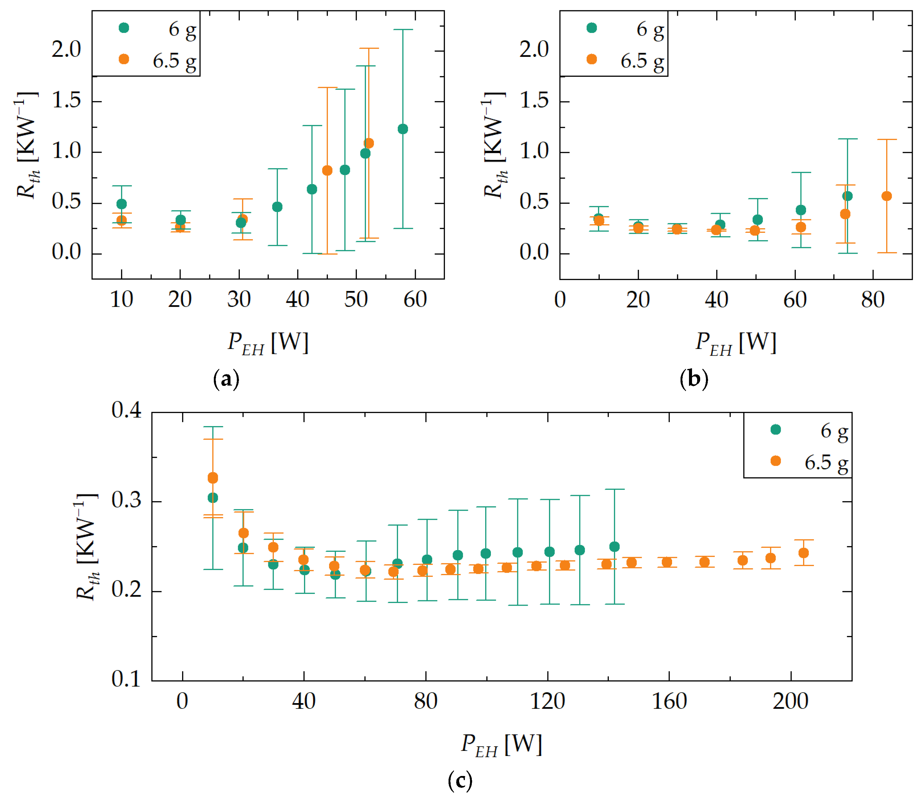
3.1.2. Thermal Resistance

In all orientations, minimum thermal resistances of ca. 0.25 KW−1 were observed. In all experiments, a slight decrease in thermal resistance can be observed for lower evaporator heat inputs in the range of 10 to 30 W. It is assumed that this is due to a kind of VCHP effect. Increasing heat inputs at the evaporator and correspondingly higher temperatures result in an increase in vapor pressure, leading to the compression of the NCG that accumulated in the condenser, thus lowering the thermal resistance.
The dry-out indicators show that the experiments with a demonstrator’s water loading of 6.5 g yield better results. Before reaching the heat transfer limit, the temperature deviations at the evaporator are smaller for all orientations. Furthermore, the indicators show that the heat pipe reached its heat transfer limitation before reaching the experiment termination temperature of 150 °C for the experiments with horizontal and against-gravity orientation. In vertical orientation, the heat pipe does not show any significant evaporator dry-out even at the experiment termination temperature. Compared to the experiments with other orientations, the temperature deviations remain at a low level.

3.1.3. Interim Summary

In general, it can be observed that an adsorption-based heat pipe can be operated in against-gravity orientation. The evaluated minimum thermal resistances of 0.25 KW−1 are comparable to conventional heat pipes similar in dimensions (0.15 to 0.75 KW−1) [20], and represent a significant improvement over the previous work given in reference [13], where minimum thermal resistances of ca. 7 KW−1 were measured. The use of an enameled copper wire with significantly increased winding density has proven to be an enhancement.
The measured power limits are in the same order of magnitude as the manufacturer’s specification of 100 W in a vertical orientation. Furthermore, theoretical studies on the capillary limit have shown that heat pipes with a wick in horizontal or against-gravity orientation exhibit significantly lower power limits compared to the vertical orientation [21]. It can be assumed that due to the structural modifications (integration of heat pipe in demonstrator), there is no significant influence on the maximum heat transfer rate of the heat pipe.

3.2. Switching Temperature and Hysteresis

3.2.1. Influence of Orientation

The results of the ramp experiments with demonstrator D1 with different orientations ϕ, a water loading of 6 g and a ramp rate of 0.2 Kmin−1 are shown in Figure 6. The graph shows the heat pipe’s thermal resistance R t h plotted against the average adsorbent reservoir temperature T r e s . Differences in hysteresis behavior due to the varying influence of gravity can be observed. In particular, the hysteresis behavior in the vertical orientation differs from the hysteresis behavior of the other examined orientations, as will be explained below.
During the ramp-up phase, the switching on process in vertical orientation starts at an average adsorbent reservoir temperature of ca. 57 °C and is completed at approximately 66 °C. The thermal resistance decreases from ca. 7 KW−1 during off state operation to approximately 0.5 KW−1 during on state operation. After the temperature is further raised to a value of approximately 85 °C, it is maintained at a plateau, followed by the ramp-down phase. During the ramp-down phase, the transition between off and on state starts at an average adsorbent reservoir temperature of ca. 60 °C, and is completed at approximately 53 °C. After the switching off process, the demonstrator returns to its initial state.
It is noticeable that the switching on process occurs at higher average adsorbent reservoir temperatures than the switching off process. This is due to the thermal resistance between the reservoir heater and the adsorbent. The resulting hysteresis has a width of ca. 10 K, meaning that ramp rates with magnitudes of 0.2 K min−1 result in a 5 K deviation from the steady state switching temperature of 60 °C.
The hysteresis in horizontal and against gravity-orientation differs compared to vertical orientation. The hysteresis appears to be shifted towards higher average adsorbent reservoir temperatures. In general, reaching similar thermal resistances at higher adsorbent reservoir temperatures suggests an increased fluid demand in the respective orientation. This is due to the influence of gravity. In vertical orientation, the wick primarily fills in the axial direction. Consequently, the heat pipe becomes wetted in the longitudinal direction, even at low wick saturation, resulting in lower thermal resistances. In contrast, in the other orientations, gravity does not support the axial flow of water, and the wick primarily fills in the radial direction. Accordingly, more fluid is required to achieve the same wetting in the longitudinal direction compared to the vertical orientation. Iverson [22] and Zhao [23] have observed a similar behavior, noting that heat transport capabilities of saturated wick structures are less affected by the applied heating power in horizontal and against-gravity orientations compared to the vertical orientation.
In addition to the shift, the lower part of the hysteresis appears to be distorted towards higher average adsorbent reservoir temperatures. In this case, the cause is suspected to be the unfavorable design of the adsorbent reservoir heat exchanger of D1, which promotes high temperature variations within the adsorbent grain bed. Grains not in direct contact with a heated surface experience a slower temperature rise, causing a delayed desorption of water. This effect is not observed in the vertical orientation since a lower amount of water is required to achieve a low thermal resistance. This assumption will be further investigated in the next section.

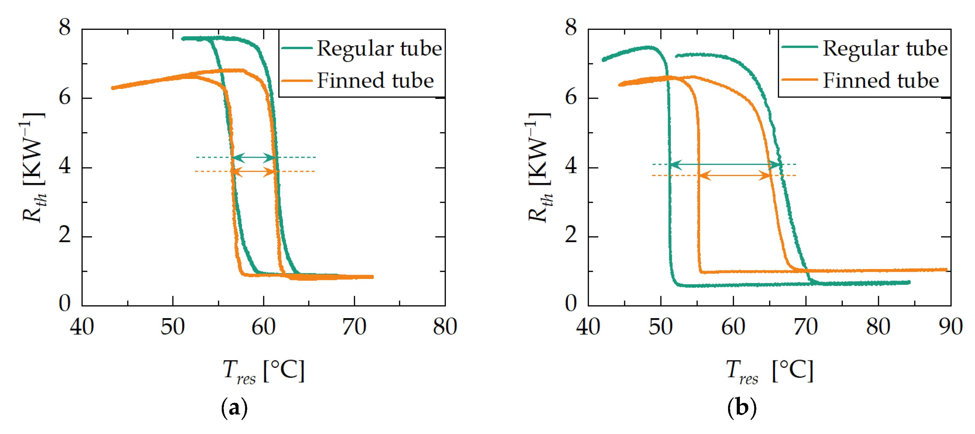
3.2.2. Influence of Ramp Rate and Adsorbent Reservoir Heat Exchanger Design

To assess how the heat exchanger design affects the dynamic properties of switchable heat pipes based on adsorption, an additional ramp experiment was conducted. In this experiment, the behaviors of the two demonstrators D1 and D2 at high and low ramp rates in vertical orientation (ϕ = 90 °) were examined. The graphs in Figure 7 display the heat pipe’s thermal resistance R t h plotted against the average adsorbent reservoir temperature T r e s , with a ramp rate of 0.05 Kmin−1 on the left and 0.63 Kmin−1 on the right. It can be observed that the demonstrators exhibit different hysteresis behaviors with respect to varying ramp rates.
At low ramp rates, both forms of hysteresis are approximately symmetric and roughly overlap with each other. The width of the hysteresis, which is interpreted as the temperature difference between the switch on and switch off curves at mean thermal resistance ( R t h , o f f + R t h , o n )/2 (see arrows in Figure 7), amounts to 5 K for both demonstrators. Consequently, the deviation from the steady state switching temperature of 60 °C (see Section 2.1.2) is the same for both demonstrators, amounting to 2–3 K.
At high ramp rates, both hysteresis forms are similar in shape but do not overlap with each other. Demonstrator D1 exhibits a hysteresis width of 15 K, while Demonstrator D2 has a hysteresis width of 10 K. Consequently, D2 exhibits smaller deviations from the steady state switching temperature than D1, although the deviations are generally higher compared to the low-ramp-rate experiment. Furthermore, both hysteresis forms are asymmetric. The switching on process extends across a larger range of average adsorbent reservoir temperatures, whereas the switching off process occurs at a nearly constant average adsorbent reservoir temperature.
It can be observed that lower ramp rates lead to narrower hysteresis around the steady state switching temperature. Consequently, it is expected that when passing through steady states, the transfer function of the demonstrator will be obtained. With higher ramp rates, dynamic effects come into play, which result in deviations from the steady-state behavior and strongly depend on the design of the heat exchanger.
For the adsorbent grain beds used in this study, the heat-up is mainly determined by (i) the thermal resistance between the heated surface and the grains and (ii) the thermal resistance between the grains. At low ramp rates and a corresponding slow heat-up, the transport of heat to the adsorbent bed is limited by the thermal resistance between the heated surface and the grains. Roughly all parts of the bed show an equilibrium curve of the adsorbent at approximately the same rate. The result is the demonstrator’s transfer function, which is a superposition of the adsorption characteristic and the thermal resistance of the heat pipe in terms of its fluid load.
At high ramp rates and a correspondingly fast heat-up, the transport of heat to the adsorbent bed is limited by the thermal resistance between the grains. As a result, parts of the bed close to the heated surface reach the target temperature faster and desorb significant amounts of water, while other parts of the bed remain at a lower temperature. The resulting curve of the thermal resistance plotted against the average adsorbent reservoir temperature diverges from the transfer function.
The different shapes of the on and off processes at high ramp rates are due to the equalization of temperature differences within the adsorbent bed through the deposition of adsorption heat, resulting in the off process occurring at approximately constant temperature.

3.2.3. Interim Summary

With the ramp experiment, the impacts of the heat pipe’s orientation and the design of two loose grain adsorbent reservoir heat exchangers on the demonstrator’s dynamic properties and the deviation of its steady-state transfer function was examined. It can be concluded that the orientation affects the demonstrator’s dynamic properties. This is because heat pipes with wicks in different orientations achieve the same thermal resistance at different fluid loads. Furthermore, demonstrator D2 delivers better results in terms of its dynamic properties due to a significantly larger heat transfer surface area, smaller adsorbent grains, and thus improved heat transfer between its heat exchanger structure and the adsorbent grains.
The necessity of an improved adsorbent heat exchanger with increased space requirements depends on the specific application of the adsorption-based heat pipe. If the heat source is expected to undergo only very slow temperature increases, an adsorbent reservoir without a special heat exchanger structure may be sufficient.

3.3. Switching Time

This section focuses on presenting the influence of the adsorbent heat exchanger design and the power supply limitations of the experimental setup.

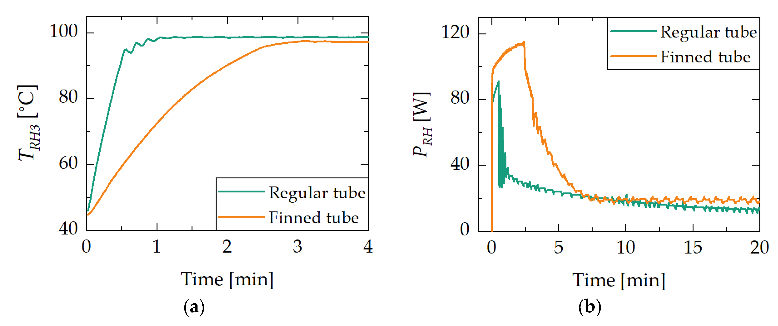
3.3.1. Influence of Adsorbent Heat Exchanger Design

Figure 8 compares the results of the jump experiment in vertical orientation (ϕ = 90°) with the demonstrators D1 and D2, each loaded with 6 g of water. The graph shows the heat pipe’s thermal resistance plotted against time. It can be observed that the finned tube adsorbent reservoir demonstrator D2 reaches its minimum thermal resistance significantly faster than the regular tube adsorbent reservoir demonstrator D1. The switching time is interpreted as the duration between the start of the temperature jump and the point at which the inflection tangent of the jump response intersects the level of minimum thermal resistance (see lines in Figure 9). Hence, demonstrator D2 has a lower switching time than D1.
The reservoir heater temperature step starts at 0 s. At the beginning of the experiment, both demonstrators are in the off state and have a thermal resistance of 6.5 KW−1. Upon activation and reaching the on state, the thermal resistance drops to ca. 0.5 KW−1. While the regular tube adsorbent reservoir demonstrator D1 reaches its on state after ca. 12.5 min, the finned tube adsorbent reservoir demonstrator D2 takes only about 5 min.
As already shown in the ramp experiments, an improved adsorbent heat exchanger design leads to improved dynamic properties of the demonstrator. This is also reflected in the switching time. Demonstrator D2 requires ca. 60% less time than D1 for the switching on process.

3.3.2. Power Supply and Limitations

A look at the temperature profile of the reservoir heater and the supplied power provides insights into the limitations of the experimental setup. Figure 9 compares the reservoir heater temperature (Figure 9a) and the supplied power at the reservoir heater (Figure 9b), each plotted against the time for the demonstrators D1 and D2 during the jump experiment. It can be observed that the regular tube adsorbent reservoir demonstrator D1 reaches the target temperature T R H 3 = 100   ° C faster, while the finned tube adsorbent reservoir of D2 reaches thermal equilibrium faster.
Figure 9. Results of the jump experiment with demonstrator D1 and D2. Figure (a) shows the temperature T R H 3 of the reservoir heater plotted against time. Figure (b) shows the reservoir heater’s supplied power P R H plotted against time. The regular tube adsorbent reservoir demonstrator D1 reaches the target temperature T R H 3 = 100   ° C faster, while the finned tube adsorbent reservoir of D2 reaches thermal equilibrium faster.
Energies 17 02088 g009
In Figure 9a, it can be seen that the reservoir heater of demonstrator D1 reaches the target temperature of 100 °C after 1 min, while D2 takes ca. 3 min. Figure 9b shows that the power supplied to the reservoir heater also differs between D1 and D2. The maximum supplied power for D2 amounts to ca. 115 W and to 90 W for D1. After ca. 1 min and 2.5 min a sharp drop in the supplied power is observed for D1 and D2, respectively. Furthermore, D2 reaches an approximately constant power level after 7 min, while D1 takes ca. 17 min. The respective power levels are 12 W for D1 and 18 W for D2.
To achieve the same temperature step in the reservoir heater in the same amount of time, D2 generally requires more energy. This is due to the increased thermal mass resulting from the increased length and more material (finning of the tube). An analysis of the voltage and current data has revealed that for both jump experiments, the power supply runs into its current limit (5 A) during the first minutes of the experiment. Hence, it can be expected that with a larger power supply unit the target temperature would have been reached faster, further reducing the switching time of D2.
The fact that the temperature-controlled power supply reaches an approximately constant level in the case of D2 earlier than D1 supports the hypothesis that the design of the adsorbent heat exchanger in D1 promotes larger temperature differences within the adsorbent grain bed, and therefore exhibits poorer dynamic characteristics. This proves that the heat exchanger design of D2 is more effective in reaching its thermal equilibrium.

3.3.3. Interim Summary

It has been demonstrated that the adsorption-based heat pipe can be used as a thermal switch. With the improved adsorbent heat exchanger design of demonstrator D2, minimum switching on durations of approximately 5 min were measured. This indicates that the design of the adsorbent heat exchanger is the key to improving the adsorption-based heat pipe with regard to its dynamic characteristics.
Furthermore, it has been demonstrated that the power supply controlling the adsorbent reservoir also plays an important role. In general, the switching time strongly depends on the amount of supplied power. The higher the power limit of the supply, the shorter the potential switching on duration. However, it is important to consider that there is a thermal coupling between the adsorbent reservoir and heat pipe. Consequently, an inefficient input of heat at the adsorbent reservoir may lower the heat pipe’s power limit during the switching on process because the heat pipe may remove portions of the heat input at the adsorbent reservoir.

3.4. Switching Ratio

By considering the evaluated thermal resistances of 6.5 KW−1 in the off state from the jump experiment and a minimum thermal resistance of 0.25 KW−1 in the on state from the max Q ˙ experiment, a switching ratio of 26 is obtained. This value represents an improvement compared to the previous work as given in [13], which is mainly attributed to the reduction in thermal resistance in the on state.

4. Conclusions

In this work, thermal switching and regulation using a heat pipe and a water-loaded adsorbent were examined. For this purpose, a comprehensive experimental characterization of two new developed demonstrators was conducted. From the obtained results, we conclude the following:
  • Against-gravity operation—With the extension of a heat pipe with wick structure by an adsorbent reservoir, a system was built that can be used both as a thermal switch and a thermal regulator, which can be operated also in against-gravity orientation. The results of the experimental investigations suggest that the thermal resistance and the maximum heat transfer rate in the on state of the component correspond to those of a conventional heat pipe. Thereby, it has been demonstrated that the adsorption-based heat pipe has the potential to compensate for the drawbacks of the existing solutions, as presented in the introduction of this work;
  • Dynamic performance—Investigations of dynamic properties have revealed that the heat exchanger design of the adsorbent reservoir is crucial for achieving short switching times and minimal deviations of the steady state switching temperature. The results of the experimental investigations have shown that a finned tube heat exchanger with loose adsorbent grains provides significant improvements in terms of dynamic properties compared to a regular tube heat exchanger. Thus, the adsorption-based heat pipe is suitable for applications that impose high demands on the time response of thermal components;
  • Size and weight—In this work, the adsorbent reservoir and the heat pipe are approximately the same size. The use of heat exchanger structures such as finned tubes further increases the weight and volume of the system. Hereby, a conservative design specification is proposed, which assists in the design of thermal management systems using adsorption-based heat pipes.
Furthermore, potential limitations of the assumptions that were made, as well as of the current design and the experimental setup, were identified:
  • Constant condenser temperature—Unlike in this study, the temperature of the heat sink and therefore the temperature of the condenser is not necessarily constant in real-life applications;
  • Power supply limitation—The power supply of the reservoir heater ran into its current limitation during the jump experiments with the finned tube adsorbent reservoir demonstrator D2;
  • Adsorbent and Adsorptive—As mentioned in Section 2.1.2, the characteristics of the adsorbent–adsorptive pairing have a significant influence on the switching temperature of the adsorption-based heat pipe thermal regulator. With the materials used in this work, TAPSO-34 and water, switching temperatures of 60 °C can be achieved within an operating range of 0–100 °C, which therefore may only serve a limited range of applications.
As an outlook, we identify several possible aspects of future research:
  • Varying condenser temperature—Since the condenser temperature affects the pressure within the adsorption-based heat pipe and thus the adsorption characteristics, the influence of a varying condenser temperature will be investigated in future studies;
  • Upgrade experimental setup—Implementation of a power supply for the reservoir heater with current limitation larger than 5 A to achieve lower switching times. Implementation of pressure measurement to gain deeper understanding of the adsorption and desorption processes within the adsorbent reservoir;
  • Dynamic performance—To achieve further significant improvements regarding dynamic performance, coated adsorbent heat exchangers could make an important contribution. While Guilleminot et al. [24] measured comparably low heat transfer coefficients of 20 Wm−2K−1 between the wall and loose adsorbent grains, coating the heated surface with the adsorbent material yields heat transfer coefficients up to 700 Wm−2K−1 [25];
  • Considering potential applications to better align research effort. Possible applications could include the cooling of the batteries of electric vehicles [2] or the thermal management of spacecraft [1]. Depending on the application, we can explore alternative adsorbent–adsorptive pairings for specifically altering the characteristics of the thermal component, such as the switching temperature, as well as the operating range.

5. Patents

The concept of realizing a thermal switch based on an adsorption material in a heat pipe was filed for patent (reference EP20180665.0).

Author Contributions

Conceptualization, S.B., M.W., C.T., D.S. and J.S.; methodology, S.B., D.S. and J.S.; investigation, S.B., D.S. and J.S.; writing—original draft preparation, S.B.; writing—review and editing, M.W., R.S., C.T., D.S., J.S., K.B., O.S.-W. and S.P.; visualization, S.B.; supervision, R.S., K.B. and O.S.-W.; project administration, M.W.; funding acquisition, M.W. and K.B. All authors have read and agreed to the published version of the manuscript.

Funding

This research was funded by the Fraunhofer Cluster of Excellence Programmable Materials (Funding number PT3).

Data Availability Statement

All data presented and discussed in this study are represented in the figures shown in this work, and thus are publicly available.

Conflicts of Interest

The authors declare no conflicts of interest.

References

  1. Celotti, L.; Solyga, M.; Nadalini, R.; Kravets, V.; Khairnasov, S.; Baturkin, V.; Lange, C.; Findlay, R.; Ziach, C.; Ho, T. MASCOT thermal subsystem design challenges and solution for contrasting requirements. In Proceedings of the 45th International Conference on Environmental Systems, Bellevue, WA, USA, 12–16 July 2015. [Google Scholar]
  2. Illner, M.; Thüsing, K.; Salles, A.; Trettenhann, A.; Albrecht, S.; Winkler, M. Switchable Heat Pipes for Eco-Friendly Battery Cooling in Electric Vehicles: A Life Cycle Assessment. Energies 2024, 17, 938. [Google Scholar] [CrossRef]
  3. Wehmeyer, G.; Yabuki, T.; Monachon, C.; Wu, J.; Dames, C. Thermal diodes, regulators, and switches: Physical mechanisms and potential applications. Appl. Phys. Rev. 2017, 4, 41304. [Google Scholar] [CrossRef]
  4. Li, C.; Guo, H.; Tian, X.; He, T. Size-dependent thermo-electromechanical responses analysis of multi-layered piezoelectric nanoplates for vibration control. Compos. Struct. 2019, 225, 111112. [Google Scholar] [CrossRef]
  5. Li, C.; Tian, X.; He, T. An investigation into size-dependent dynamic thermo-electromechanical response of piezoelectric-laminated sandwich smart nanocomposites. Int. J. Energy Res. 2021, 45, 7235–7255. [Google Scholar] [CrossRef]
  6. Asselman, G.A.A.; Green, B.B. Heat pipes. Philips Tech. Rev. 1973, 1973, 104–113. [Google Scholar]
  7. Benafan, O.; Notardonato, W.U.; Meneghelli, B.J.; Vaidyanathan, R. Design and development of a shape memory alloy activated heat pipe-based thermal switch. Smart Mater. Struct. 2013, 22, 105017. [Google Scholar] [CrossRef]
  8. Prado-Montes, P.; Campo, S.; García, A.; Torres, A.; Munì, M.; Negri, F. ExoMars 2020 LHPs: From the concept to the flight models. In Proceedings of the 47th International Conference on Environmental Systems, Charleston, SC, USA, 16–20 July 2017. [Google Scholar]
  9. Mock, P.R.; Marcus, D.B.; Edelman, E.A. Communications Technology Satellite: A Variable Conductance Heat Pipe Application. J. Spacecr. Rocket. 1975, 12, 750–753. [Google Scholar] [CrossRef]
  10. Tarau, C.; Ababneh, M.; Anderson, W.; Alvarez-Hernandez, A.; Ortega, S.; Farmer, J.; Hawkins, R. Advanced Passive Thermal eXperiment (APTx) for Warm Reservior Hybrid Wick Variable Conductance Heat Pipes on the International Space Station. In Proceedings of the 48th International Conference on Enviornmental Systems (ICES), Albuquerque, NM, USA, 8–12 July 2018. [Google Scholar]
  11. Leriche, M.; Harmand, S.; Lippert, M.; Desmet, B. An experimental and analytical study of a variable conductance heat pipe: Application to vehicle thermal management. Appl. Therm. Eng. 2012, 38, 48–57. [Google Scholar] [CrossRef]
  12. Winkler, M.; Teicht, C.; Corhan, P.; Polyzoidis, A.; Bartholomé, K.; Schäfer-Welsen, O.; Pappert, S. Thermal Switch Based on an Adsorption Material in a Heat Pipe. Energies 2021, 14, 5130. [Google Scholar] [CrossRef]
  13. Winkler, M.; Schipper, J.; Teicht, C.; Corhan, P.; Polyzoidis, A.; Bartholomé, K.; Schäfer-Welsen, O.; Pappert, S. Improved Thermal Switch Based on an Adsorption Material in a Heat Pipe. Energies 2022, 15, 3271. [Google Scholar] [CrossRef]
  14. Dubinin, M.M. Theory of the physical adsorption of gases and vapors and adsorption properties of adsorbents of various natures and porous structures. translated version. Russ. Chem. B 1960, 9, 1072–1078. [Google Scholar] [CrossRef]
  15. Thommes, M.; Kaneko, K.; Neimark, A.V.; Olivier, J.P.; Rodriguez-Reinoso, F.; Rouquerol, J.; Sing, K.S. Physisorption of gases, with special reference to the evaluation of surface area and pore size distribution (IUPAC Technical Report). Pure Appl. Chem. 2015, 87, 1051–1069. [Google Scholar] [CrossRef]
  16. Sauerbeck, S.; Manoylova, O.; Tissler, A.; Dienersberger, M. Titano-Silico-Alumino-Phosphate. U.S. Patent 2013/0334460 A1, 19 December 2013. [Google Scholar]
  17. Teicht, C. An easy-to-use modification of the potential theory of adsorption and creation of an adsorbent data base. Energy 2023, 263, 125968. [Google Scholar] [CrossRef]
  18. Reay, D.A.; Kew, P.A.; McGlen, R.J. Heat Pipes: Theory, Design and Applications, 6th ed.; Butterworth-Heineman: Oxford, UK, 2013. [Google Scholar]
  19. Mahdavi, M.; Tiari, S.; de Schampheleire, S.; Qiu, S. Experimental study of the thermal characteristics of a heat pipe. Exp. Therm. Fluid Sci. 2018, 93, 292–304. [Google Scholar] [CrossRef]
  20. Faghri, A. Heat Pipes: Review, Opportunities and Challenges. Front. Heat Pipes 2014, 5, 1–48. [Google Scholar] [CrossRef]
  21. Nemec, P.; Čaja, A.; Malcho, M. Mathematical model for heat transfer limitations of heat pipe. Math. Comput. Model. 2013, 57, 126–136. [Google Scholar] [CrossRef]
  22. Iverson, B.D.; Davis, T.W.; Garimella, S.V.; North, M.T.; Kang, S.S. Heat and Mass Transport in Heat Pipe Wick Structures. J. Thermophys. Heat Transf. 2007, 21, 392–404. [Google Scholar] [CrossRef]
  23. Zhao, T.S.; Liao, Q.; Cheng, P. Variations of Buoyancy-Induced Mass Flux From Single-Phase to Two-Phase Flow in a Vertical Porous Tube with Constant Heat Flux. J. Heat Transf. 1999, 121, 646–652. [Google Scholar] [CrossRef]
  24. Guilleminot, J.J.; Choisier, A.; Chalfen, J.B.; Nicolas, S.; Reymoney, J.L. Heat transfer intensification in fixed bed adsorbers. Heat Recovery Syst. CHP 1993, 13, 297–300. [Google Scholar] [CrossRef]
  25. Frazzica, A.; Füldner, G.; Sapienza, A.; Freni, A.; Schnabel, L. Experimental and theoretical analysis of the kinetic performance of an adsorbent coating composition for use in adsorption chillers and heat pumps. Appl. Therm. Eng. 2014, 73, 1022–1031. [Google Scholar] [CrossRef]
Figure 1. Basic concept of the adsorption-based heat pipe: A heat pipe is extended by an adsorbent reservoir that holds adsorbent grains, which desorb (left) and adsorb (right) the working fluid of the heat pipe. In the on state on the left side, heat is transferred by the evaporation and condensation of the working fluid. In the off state on the right side, heat is only transferred by conduction through the container/wick material.
Energies 17 02088 g001
Figure 2. Schematic of the experimental setup at vertical orientation (ϕ = 90°). The labels of temperature and power measuring points are explained in Section 2.1.4.
Energies 17 02088 g002
Figure 3. Cross-sectional view of the adsorbent reservoir of D1 and D2.
Energies 17 02088 g003
Figure 4. Temporal progression of the supplied power at the evaporator heater P E H and the controller’s set reservoir heater temperature T R H 2 for the ramp, jump and max Q ˙ experiment.
Energies 17 02088 g004
Figure 5. Results of the max Q ˙ experiment with against-gravity (a), horizontal (b) and vertical orientations (c) of the heat pipe and different water loadings of demonstrator D1. Each dot represents the heat pipe’s thermal resistance R t h in a steady state for different evaporator heater powers P E H . The error bars represent an indicator of temperature deviations along the evaporator region, indicating the degree of evaporator dry-out. Limits of the heat transfer rate in different orientations can be observed.
Energies 17 02088 g005
Figure 6. Results of the ramp experiment with demonstrator D1. Each curve represents the heat pipe’s thermal resistance R t h plotted against the average adsorbent reservoir temperature T r e s for different orientations ϕ with a water loading of 6 g. Differences in hysteresis behavior can be observed.
Energies 17 02088 g006
Figure 7. Results of the ramp experiment with regular tube adsorbent reservoir demonstrator D1 and finned tube adsorbent reservoir demonstrator D2. Each curve represents the heat pipe’s thermal resistance R t h plotted against the average adsorbent reservoir temperature T r e s for vertical orientation (ϕ = 90°) with a water loading of 6 g. Figure (a,b) show the ramp experiment with a ramp rate of 0.05 Kmin−1 and 0.63 Kmin−1, respectively. Differences in hysteresis behavior can be observed. Arrows represent hysteresis width.
Energies 17 02088 g007
Figure 8. Results of the jump experiment using demonstrator D1 and D2. Each curve represents the heat pipe’s thermal resistance R t h plotted against the time for vertical orientation with a water loading of 6 g. The finned tube adsorbent reservoir demonstrator D2 has a significantly lower switching time than the regular tube adsorbent reservoir demonstrator D1. Dashed line and arrow: see explanation above graph.
Energies 17 02088 g008
Table 1. Heat pipe properties.
PropertyUnitValue
Original state lengthmm400
Total length 1mm390
Evaporator lengthmm100
Adiabatic zone lengthmm80
Condenser lengthmm200
Outer diametermm10
Wall thicknessmm0.5
Average wick thicknessmm0.87
1 Remaining length of the heat pipe after its head end was cut off.
Table 2. Adsorbent reservoir properties of demonstrator D1 and D2.
PropertyUnitValue
D1D2
Adsorbent grain sizemm1.5 to 30.5 to 1
Outer tube length l R o mm172249
Inner tube length l R i mm152230
Outer tube outer diametermm22
Inner tube outer diameter mm1012
Outer tube wall thicknessmm1
Inner tube wall thicknessmm1
Inner tube outside area per lengthm2m−10.030.18
Reservoir heater length l R H mm200300
Reservoir heater diameter d R H mm810
Table 3. Measurement uncertainties.
PropertyUnitValue
TemperatureK±0.33 1
VoltageµV±(0.05% of m.v. 2 + 10)
Electrical resistance±0.0375
1 The temperature measurement uncertainties were determined from the calibration data of the respective thermocouple. This calibration was performed by TC Regeltechnik and Dostmann electronic (Wertheim, Germany). 2 m.v. = measured value.
Table 4. Uncertainty of evaluated data.
PropertyUnitUncertainty
Average adsorbent reservoir temperature T r e s K0.16
Off state thermal resistance R t h , o f f KW−10.07
On state thermal resistance R t h , o n KW−10.05
Table 5. Main figures of max Q ˙ experiments.
PropertyUnitValue
Orientation°900−16
Loadingg66.566.566.5
P m a x W14220472835752
P @ R t h , m i n W506930493020
R t h , m i n KW−10.220.220.250.230.280.25
R t h @ P m a x KW−10.250.240.570.571.231.09
Disclaimer/Publisher’s Note: The statements, opinions and data contained in all publications are solely those of the individual author(s) and contributor(s) and not of MDPI and/or the editor(s). MDPI and/or the editor(s) disclaim responsibility for any injury to people or property resulting from any ideas, methods, instructions or products referred to in the content.

