A Method to Use Solar Energy for the Production of Gas from Marine Hydrate-Bearing Sediments: A Case Study on the Shenhu Area


Abstract
:
1. Introduction
2. Solar Energy Method
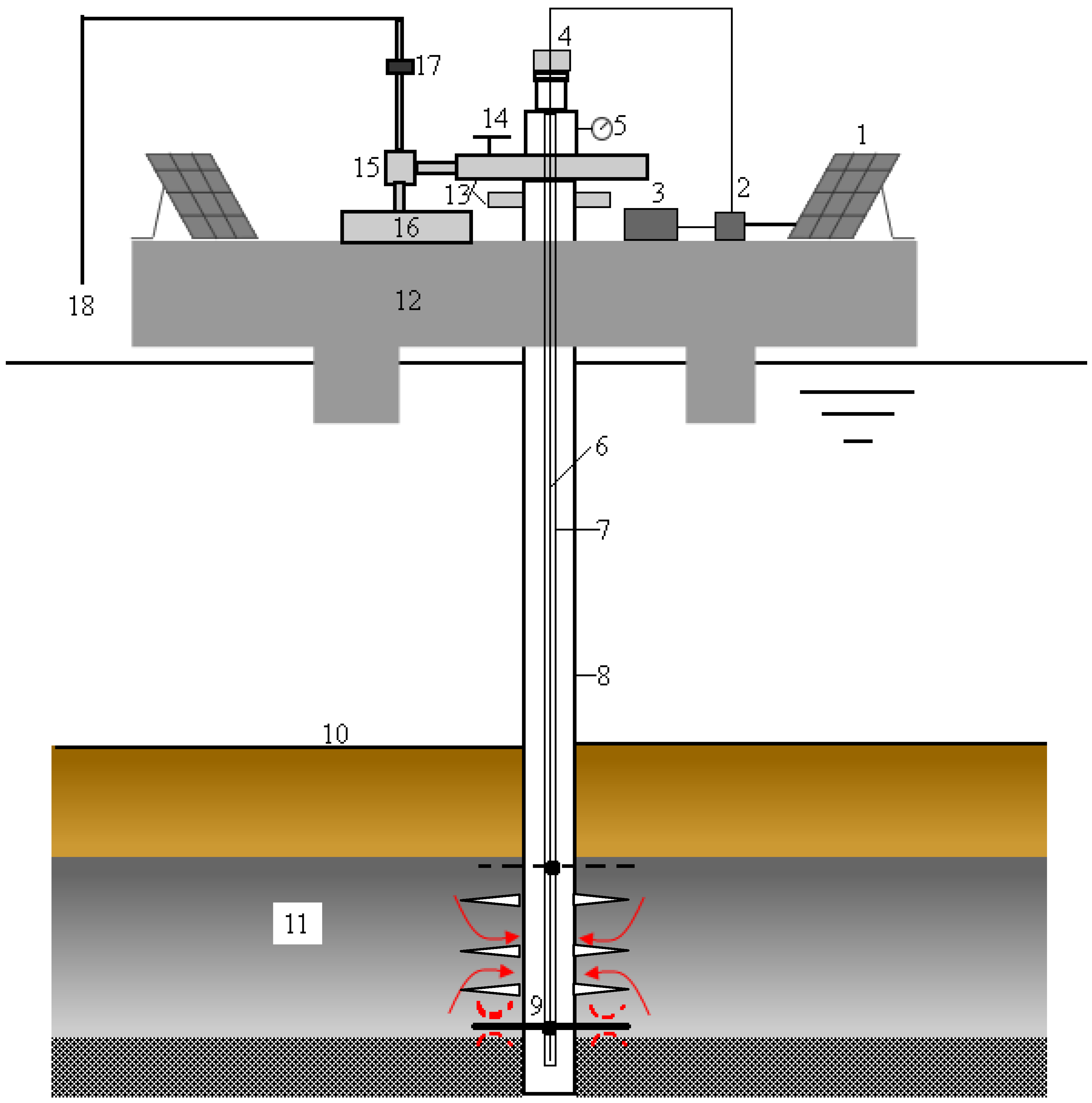
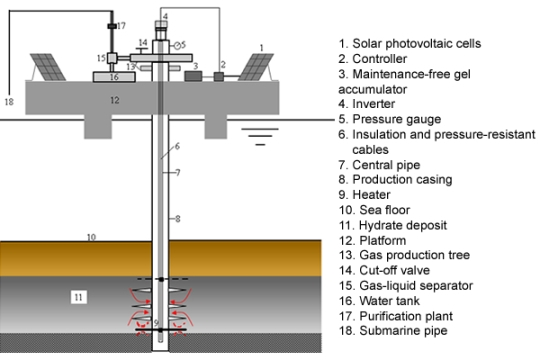
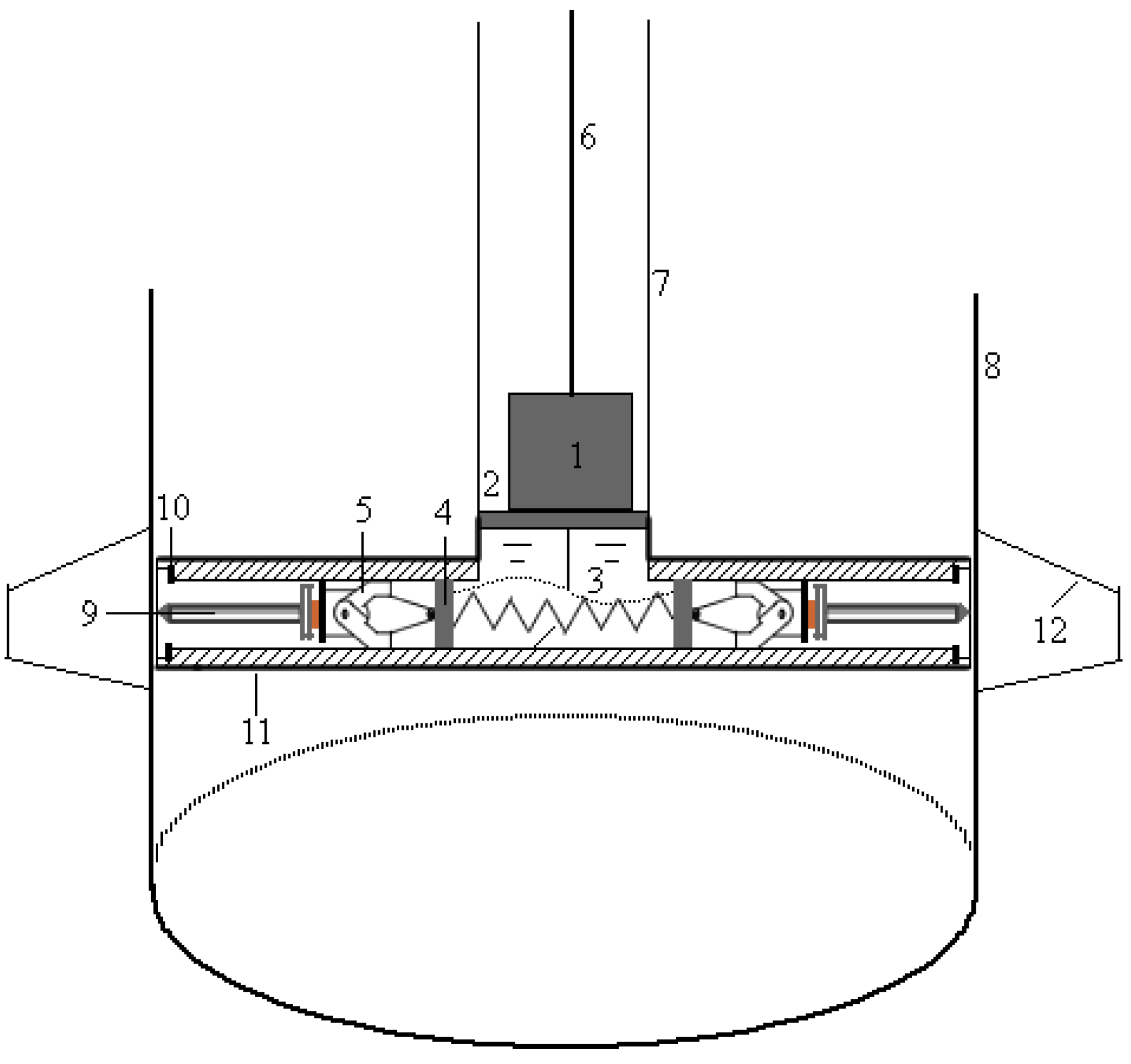
2.1. Principle Description
2.2. System Composition
2.3. Operational Procedures

3. Basic Parameters
3.1. Power of the Heaters
- Q hyd: Quantity of heat needed to make hydrates decompose (J).
- : Quantity of heat needed to make the hydrate-sediment temperature increase degree (J).
- QL: Various heat losses during the heating hydrate-bearing sediment (J).
- mhyd: Mass of hydrates (kg).
- mwater: Mass of water (kg).
- mform: Mass of the matrix of hydrate-bearing formation (kg).
- Chyd: Heat capacity of methane hydrate at constant pressure (J/kg.°C).
- Cwater: Heat capacity of water at constant pressure (J/kg.°C).
- Cform: Heat capacity of the sediment matrix at constant pressure (J/kg.°C).
- qmeth: Average daily production (standard condition, m3/d).
- rg: Degree of gas recovery, %.
- ρmeth: Methane density (standard condition, kg/m3).
- ρwater: Water density (kg/m3).
- ρhyd: Density of methane hydrate (kg/m3).
- ρform: Density of matrix of hydrate-bearing formation (kg/m3).
- Hh: Heat of hydrate decomposition (J/mol).
- Mmeth: Molecular weight of methane.
- Mwater: Molecular weight of water.
- Mhyd: Molecular weight of hydrate, Mhyd = Mmeth + 6 Mwater.
- Swater: Water saturation.
- Shyd: Hydrate saturation, .
- : Porosity of sediment.
- Teqm: Hydrate equilibrium temperature, °C.
- Tform: Sediment temperature, °C.
- Therefore, the power needed for each heater can be estimated by using Equation 3:
- P: Heater power (kW).
- S: Safety margin, normally range between 1.1–1.2.
- n: Number of heaters.
- t: Work time of the heater (h).
- : Thermal-conversion efficiency of the heater, which normally has a value between 0.9–1.
3.2. Power of the Solar Cell Array
- Step 1: Calculate the accumulator capacity:
- Cb: Capacity of the accumulator (Ah).
- U: Operating voltage of heaters (V).
- Nl: The longest lasting days which are rainy/cloudy days (d)
- Tm: Correction coefficient of temperature, its value is 1 when the ambient temperature is above 0 °C; it is 1.1 when the temperature is between −10–0 °C; and 1.2 when the temperature is below −10 °C.
- CC: Depth of discharge of the accumulation, normally equal to 0.8.
- ηc: Conversion efficiency of the inverter, normally equal to 0.9.
- Step 2: Calculate the number of serial panels Ns:
- Ns: The number of serial panels.
- UR: Minimum output voltage of the solar array (V).
- Uoc: Optimum operating voltage of single module of the solar cell (V).
- Uf: Floating charge voltage of the accumulator battery (V).
- UD: Diode drop, normally equal to 0.7V.
- UC: Voltage drop caused by other factors (V).
- Step 3: Calculate the number of parallel panels Np:
- Np: The number of parallel panels.
- Nw: Minimum number of days between two longest lasting days which are rainy/cloudy days. During this period, the power generated is not only for load working, but it is also compensating for the loss of accumulator energy which is consumed during the longest lasting days under rainy/cloudy day.
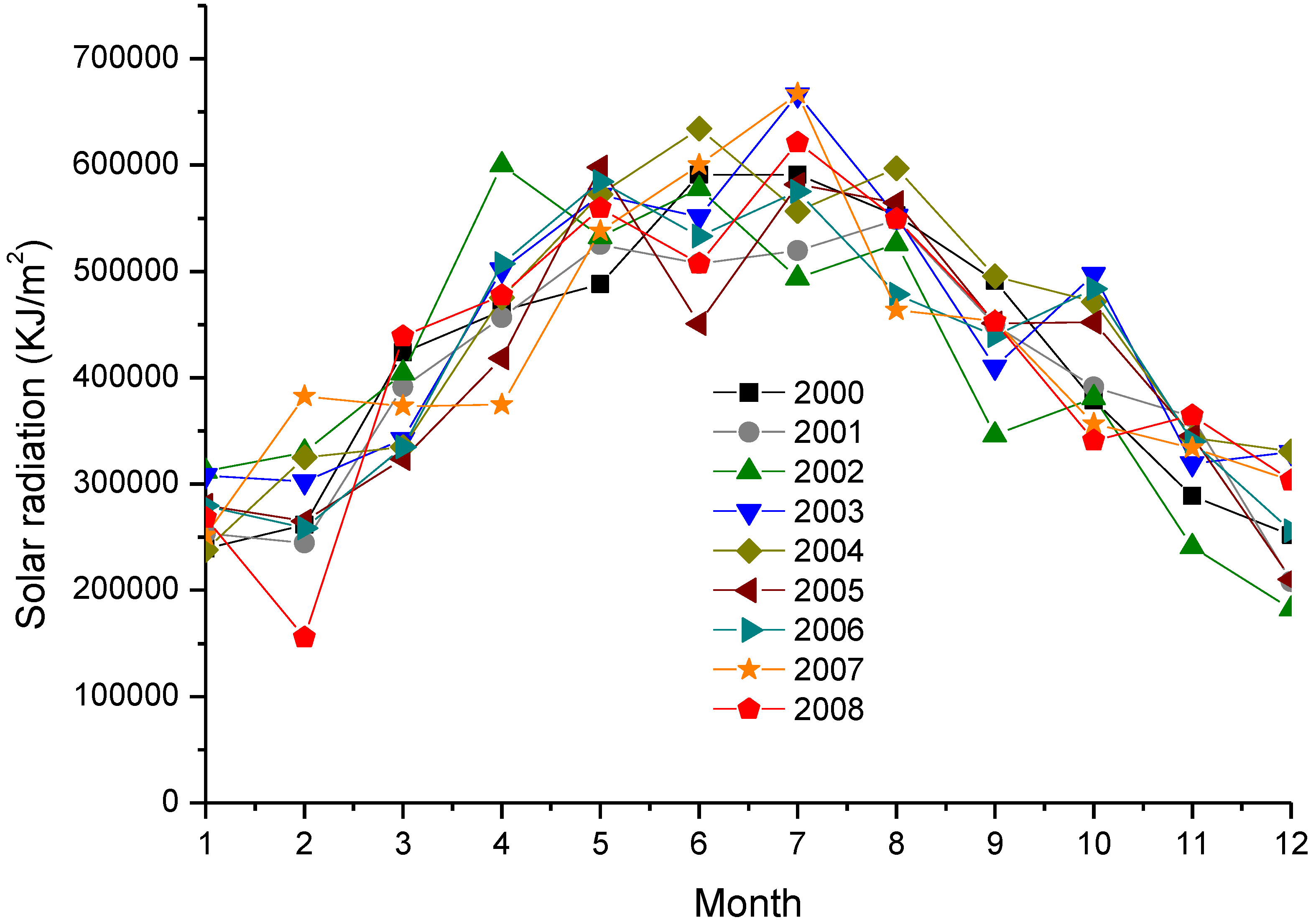
- Ht: Annual average of daily solar radiation at the water level of the hydrates-bearing zone (kJ/m2).
- Cz: Correction factor, considering the loss of combination, attenuation, dust, and controller efficiency, normally equal 0.8.
- Ioc: Optimum operating current of a single module of solar cell (A).
- Kop: Coefficient of incline correction.
- Step 4: Calculate the power of the solar array (unit: W):
- Ps: Power of the solar array (W).
- Po: Rated power of a single module of solar battery (W).
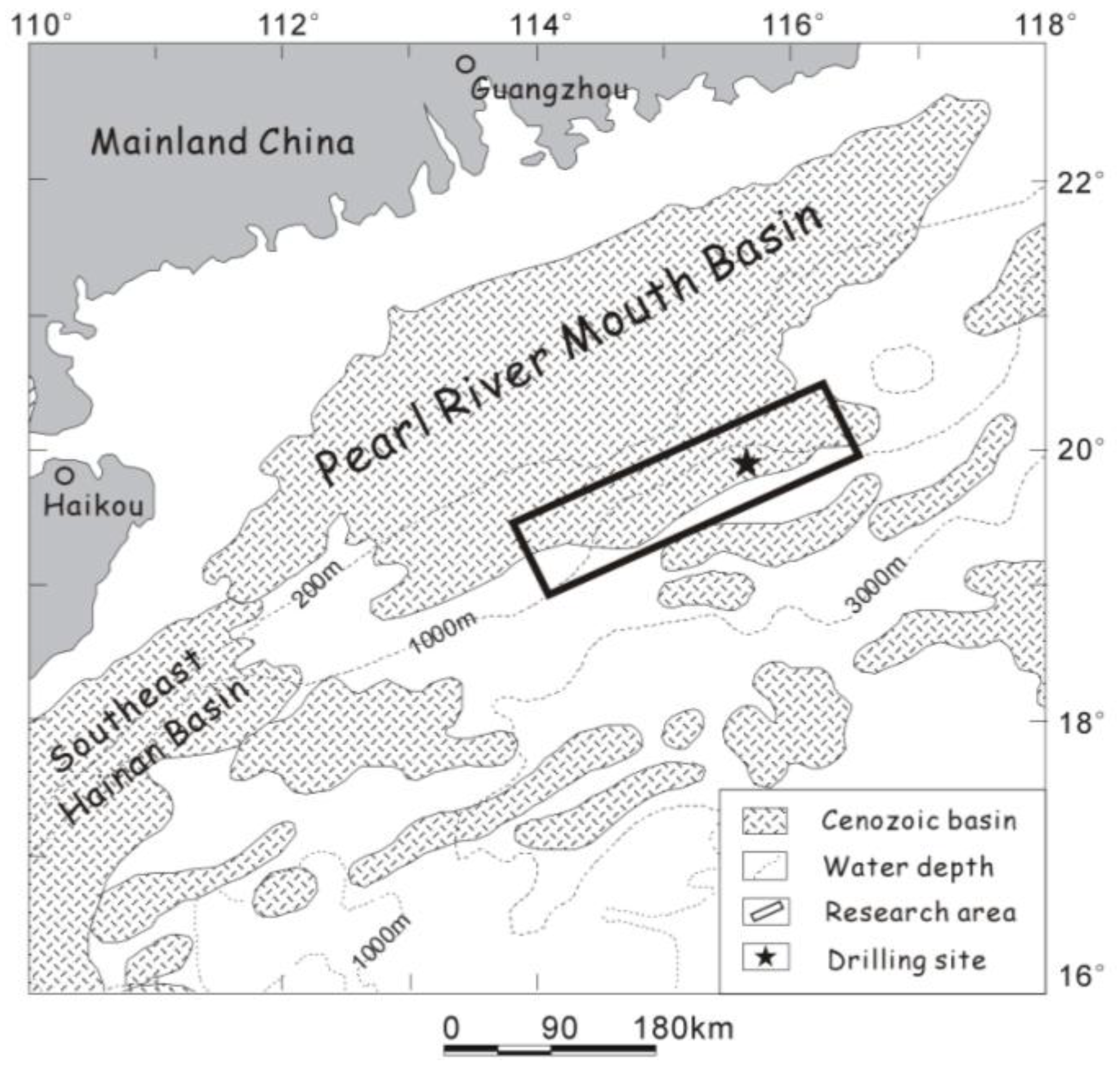
4. An Example from the Shenhu Arza, in the South China Sea
4.1. Background Information
4.2. Calculations

| Parameter | Value | Parameter | Value | Parameter | Value |
|---|---|---|---|---|---|
| qmeth | 10,000 m3/d | rg | 0.8 | ρmeth | 0.714 kg/m3 |
| ρwater | 1,000 kg/m3 | ρhyd | 910 kg/ m3 | ρform | 2,000 kg/m3 |
| Chyd | 2,500 J/kg.°C | Cwater | 4,200 J/kg. °C | Cform | 880 J/kg.°C |
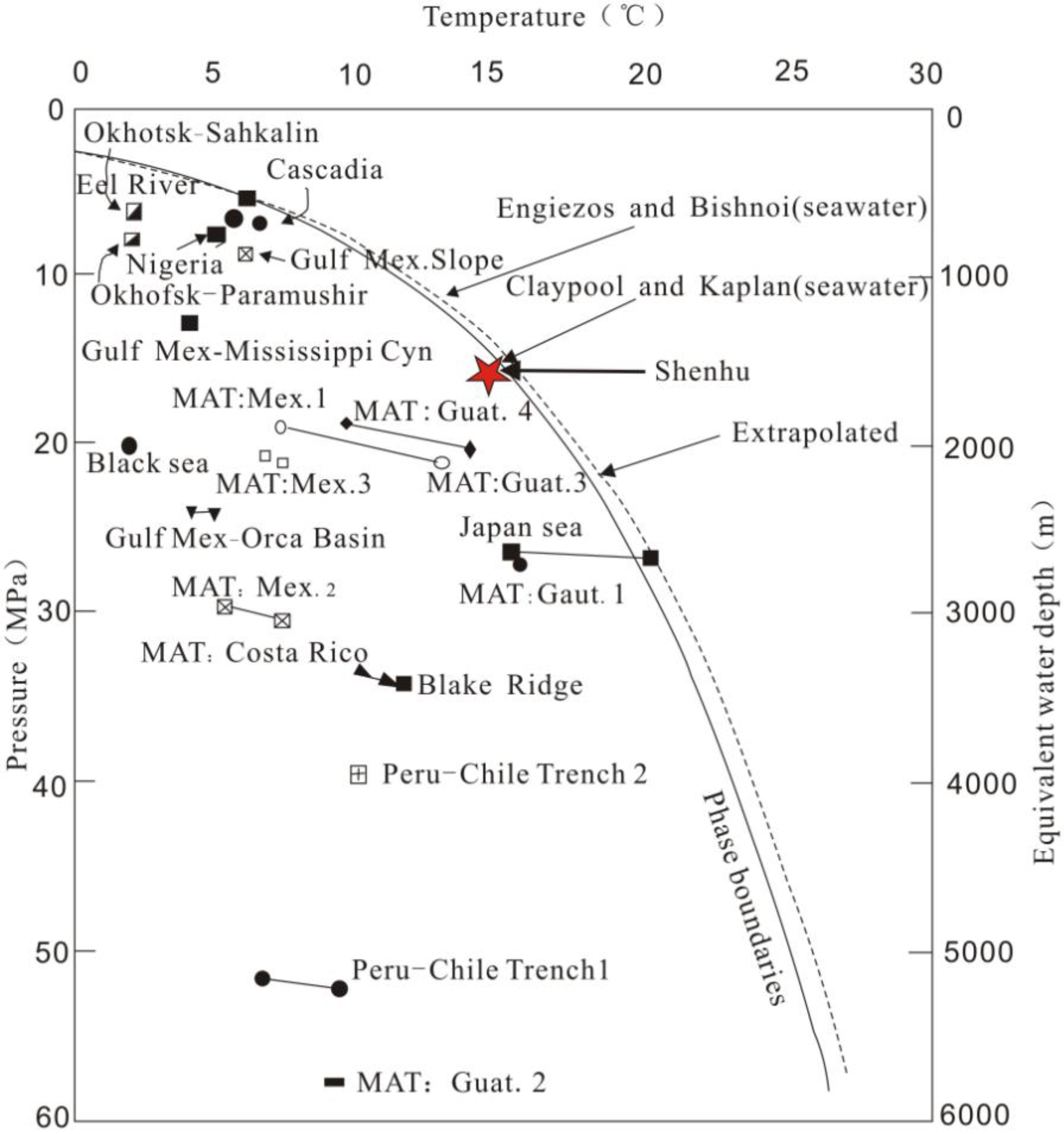
| Hh | 54190 J/mol | Teqm | 15.4 °C | Tform | 14.9 °C |
| Swater | 0.7 | Shyd | 0.3 | ϕ | 40% |
| Mmeth | 16 | Mwater | 18 | Mhyd | 124 |
4.3. Discussion of Technology and Economy

5. Conclusions and Suggestions
Acknowledgments
References and Notes
- Makogon, Y.F. Natural gas hydrates—A promising source of energy. J. Nat. Gas Sci. Eng. 2010, 2, 49–59. [Google Scholar] [CrossRef]
- Sloan, E.D. Introductory overview: Hydrate knowledge development. Am. Mineral. 2004, 89, 1155–1161. [Google Scholar]
- Sloan, E.D.; Koh, C.A. Clathrate Hydrates of Natural Gases, 3rd ed.; CRC Press, Taylor & Francis Group: Boca Raton, FL, USA, 2008; pp. 1–30; pp. 569–571. [Google Scholar]
- Makogon, Y.F.; Holditch, S.A.; Makogon, T.Y. Natural gas-hydrates—A potential energy source for the 21st Century. J. Petrol. Sci. Eng. 2007, 56, 14–31. [Google Scholar] [CrossRef]
- These estimated temperatures and pressures are obtained by checking the Kvenvolden methane hydrate stability diagram in permafrost and ocean sediment and Booth et al. marine hydrate sample data, respectively. Please see Figure 5 and Chapter 7 of monograph in Reference3.
- National Research Council of the National Academies. Realizing the Energy Potential of Methane Hydrate for the United States; The National Academies Press: Washington, DC, USA, 2010; p. 6. [Google Scholar]
- Dickens, G.R. The potential volume of oceanic methane hydrates with variable external conditions. Org. Geochem. 2001, 32, 1179–1193. [Google Scholar]
- Sloan, E.D. Fundamental principles and applications of natural gas hydrates. Nature 2003, 426, 353–359. [Google Scholar] [CrossRef] [PubMed]
- Klauda, J.B.; Sandler, S.I. Global distribution of methane hydrate in ocean sediment. Energy Fuels 2005, 19, 459–470. [Google Scholar] [CrossRef]
- Gong, J.M.; Wang, H.X.; Chen, J.W.; Wu, Z.Q.; Li, G.; Yan, G.J. Distribution model for gas hydrate in sediments (in Chinese). Mar. Geol. Lett. 2004, 20, 6–8. [Google Scholar]
- Makogon, Y.F. Hydrates of Hydrocarbons; PennWell Publshing Co.: Tulsa, OK, USA, 1997; p. 482. [Google Scholar]
- Halleck, P.M.; Byrer, C.W.; McGuire, P.L.; Judge, A.S.; Corlett, R.C.; Barraclough, B. Proceedings of The Methane Hydrate Workshop, Morgantown, WV, USA, 29–30 March 1982.
- Malone, R.D. Gas Hydrates Topical Report–DOE/METC/SP-218 (DE85001986): Morgantown (DOE, Morgantown Energy Technology Center); Technical Report for Morgantown Energy Technology Center: Morgantown, WV, USA, 1 April 1985. [Google Scholar]
- Islam, M.R. A new recovery technique for gas production from Alaskan gas hydrates. J. Petrol. Sci. Eng. 1994, 11, 267–281. [Google Scholar] [CrossRef]
- Rogers, R.E. Decomposition with Microwaves. Natural Gas Hydrates Storage Project; Technical Report for Mississippi State University: Mississippi, MS, USA, 26 March 1999. [Google Scholar]
- Castaldi, M.J.; Zhou, Y.; Yegulalp, T.M. Down-hole combustion method for gas production from methane hydrates. J. Petrol. Sci. Eng. 2007, 56, 176–185. [Google Scholar] [CrossRef]
- Pfefferle, W.C. Method for natural gas production. U.S. Patent 7,343,971, 18 March 2008. [Google Scholar]
- Moridis, G.J.; Collett, T.; Dallimore, S.; Satoh, T.; Hancock, S.; Weatherhill, B. Numerical Studies Of Gas Production From Several Methane Hydrate Zones At The Mallik Site, Mackenzie Delta, Canada. J. Petrol. Sci. Eng. 2004, 43, 219–239. [Google Scholar] [CrossRef]
- Moridis, G.J.; Kowalsky, M.; Pruess, K. Depressurization-Induced Gas Production from Class 1 Hydrate Deposits. SPE Reservoir Eval. Eng. 2007, 10, 458–481. [Google Scholar] [CrossRef]
- Ji, C.; Ahmadia, G.; Smith, D.H. Natural gas production from hydrate decomposition by depressurization. Chem. Eng. Sci. 2001, 56, 5801–5814. [Google Scholar] [CrossRef]
- Tsypkin, G.G. Effect of decomposition of a natural gas hydrate on gas recovery from a reservoir containing hydrate and gas in the free state. Fluid Dyn. 2005, 40, 117–125. [Google Scholar] [CrossRef]
- Tang, L.G.; Li, X.S.; Feng, Z.P.; Li, G.; Fan, S.S. Control Mechanisms for Gas Hydrate Production by Depressurization in Different Scale Hydrate Reservoirs. Energy Fuels 2007, 21, 227–233. [Google Scholar] [CrossRef]
- Dallimore, S.R. Overview of the 2002 Mallik gas hydrate production research well program. In Proceedings of Fourth International Conference on Gas Hydrates, Yokohama, Japan, 19–23 May 2002; pp. 19–23.
- Hancock, S. Overview of pressure drawdown production test results for the japex/jnoc/gsc Mallik 5l-38 gas hydrate research well. In Proceedings of Mallik International Symposium, Makuhari, Japan, 8–10 December 2003.
- Hancock, S. Overview of thermal stimulation production test results for the japex/jnoc/gsc Mallik 5l-38 gas hydrate research well. In Proceedings of Mallik International Symposium, Makuhari, Japan, 8–10 December 2003.
- Williams, T.E.; McDonald, W.J.; Millheim, K. Methane Hydrate Production from Alaskan Permafrost; Technical Progress Report for Maurer Technology Inc. (US): Sugar Land, TX, USA, 31 March 2003; No. DE-FC26-01NT41331. [Google Scholar]
- Lee, H.; Seo, Y.; Seo, Y.T.; Moudrakovski, I.L.; Ripmeester, J.A. Recovering Methane from Solid Methane Hydrate with Carbon Dioxide. Angew. Chem. Int. Ed. 2003, 115, 5202–5205. [Google Scholar] [CrossRef]
- Erdil, E.; Ilkan, M.; Egelioglu, F. An experimental study on energy generation with a photovoltaic (PV)-solar thermal hybrid system. Energy 2008, 33, 1241–1245. [Google Scholar] [CrossRef]
- Buresch, M. Photovoltaic Energy Systems Design and Installation; McGraw-Hill: New York, NY, USA, 1983. [Google Scholar]
- Kelleher, J.; Ringwood, J.V. A computational tool for evaluating the economics of solar and wind microgeneration of electricity. Energy 2009, 34, 401–409. [Google Scholar] [CrossRef]
- Ning, F.L.; Jiang, G.S.; Zhang, L. Comprehensive utilization of geothermal and solar energy to exploit gas hydrates buried in oceanic sediments. In Proceedings of the 6th International Conference on Gas Hydrates (ICGH 2008), Vancouver, British Columbia, Canada, 6–10 July 2008.
- Bahgat, A.B.G.; Helwa, N.H.; Ahmad, G.E.; Shenawy, E.T. Maximum power point traking controller for PV systems using neural networks. Renewable Energy 2005, 30, 1257–1268. [Google Scholar] [CrossRef]
- Hua, C.C.; Lin, J.G.; Shen, C.M. Implementation of a DSP-controlled photovoltaic system with peak power tracking. IEEE T. Ind. Electron. 1998, 45, 99–107. [Google Scholar] [CrossRef]
- Xu, W.; Germanovich, L.N. Excess pore pressure resulting from methane hydrate dissociation in marine sediments: A theoretical approach. J. Geophys. Res. 2006, 111, B01104. [Google Scholar] [CrossRef]
- Chen, S. The simplified design of solar cell power system (in Chinese). J. Yunnan Normal Univ. 1992, 12, 104–106. [Google Scholar]
- Zhang, H.Q.; Yang, S.X.; Wu, N.Y.; Su, X.; Holland, H.; Schultheiss, P.; Rose, K.; Butler, H.; Humphrey, G.; GMGS-1 Science Team. Successful and surprising results for China’s first gas hydrate drilling expedition. Fire in the Ice. In Methane Hydrate Newsletter; 2007; Fallpp. 6–9. Available online: http://www.netl.doe.gov/technologies/oil-gas/publications/Hydrates/Newsletter/HMNews Fall07.pdf (accessed on 22 November 2010). [Google Scholar]
- Wu, N.Y.; Zhang, H.Q.; Yang, S.X.; Liang, J.Q.; Wang, H.B. Preliminary discussion on natural gas hydrate reservoir system of Shenhu area, north slope of South China Sea (in Chinese). Nat. Gas Ind. 2007, 27, 1–6. [Google Scholar]
- Lu, J.A.; Yang, S.X.; Wu, N.Y.; Zhang, G.X.; Zhang, M.; Liang, J.Q. Well logging evaluation of gas hydrates in shenhu area, south china sea (in Chinese). Geoscience 2008, 22, 447–451. [Google Scholar]
- Dickens, G.R.; Quinby, H. Methane hydrate stability in seawater. Geophys. Res. Lett. 1994, 21, 2115–2118. [Google Scholar] [CrossRef]
- Handa, Y.P. Composition, enthalpy of dissociation, and heat capacities in the range 85 to 270 K for clathrate hydrates of methane, ethane, and propane, and enthalpy of dissociation of isobutene hydrate, as determined by heat-flow calorimeter. J. Chem. Thermodyn. 1986, 18, 915–921. [Google Scholar] [CrossRef]
- Rueff, R.M. The Heat Capacity and Heat of Dissociation of Methane Hydrates: A New Approach. PhD Thesis, Colorado School of Mines, Golden, USA, 01 January 1985. [Google Scholar]
- Rueff, R.M.; Sloan, E.D.; Yesavage, V.F. Heat capacity and heat of dissociation of methane hydrate. AIChE J. 1988, 34, 1468–1476. [Google Scholar] [CrossRef]
- Natural Gas Hydrates: Properties, Occurrence and Recovery; Cox, J.L. (Ed.) Butterworth Publishers: Boston, MA, USA, 1983; pp. 1–125.
- Yamamoto, K.; Dallimore, S. Aurora-JOGMEC-NRCanan Mallik 2006-2008 Gas Hydrate Research Project Progress. Fire in the Ice. In Methane Hydrate Newsletter; 2008; Summerpp. 1–5. Available online: http://www.netl.doe.gov/mh/HMNewsSummer08/ (accessed on 22 November 2010). [Google Scholar]
- WuHan Intepower Co., Ltd. Available online: http://www.intepower.com/en/index.jsp (accessed on 22 November 2010).
- National Meteorological Information Centre. Database of Year Radiation of China (since 1957–2008). Available online: http://cdc.cma.gov.cn/ (accessed on 22 November 2010).
- Suntech Power. Datasheet of suntech-vd-280-275w. Available online: http://am.suntech-power.com/images/stories/pdf/datasheets/2010/suntech-vd-280-275w.pdf (accessed on 22 November 2010).
- Booth, J.S.; Rowe, M.M.; Fischer, K.M. Offshore gas hydrate sample database with an overview and preliminary analysis. USGS Open-File Report 96-272; 1996. Available online: pubs.usgs.gov/of/1996/of96-272/ (accessed on 22 November 2010). [Google Scholar]
- Walsh, M.; Hancock, S.; Wilson, S.; Patil, S.; Moridis, G.; Boswell, R.; Collett, T.; Koh, C.; Sloan, E.D. Preliminary report on the economics of gas production from natural gas hydrates. In Proceedings of the 6th International Conference on Gas Hydrates (ICGH 2008), Vancouver, Canada, 6–10 July 2008.
- Boswell, R.; Collett, T. The Gas Hydrates Resource Pyramid. Fire in the Ice. In Methane Hydrate Newsletter; 2006; Fallpp. 5–6. Available online: www.netl.doe.gov/mh/FITI06_Pyramid/ (accessed on 22 November 2010). [Google Scholar]
- Boswell, R. Is Gas Hydrate Energy Within Reach? Science 2009, 325, 957–958. [Google Scholar] [CrossRef] [PubMed]
- SolarBuzz. Retail price survey 2010. Available online: http://www.solarbuzz.com/ (accessed on 22 November 2010).
- U.S. Energy Information Administration. Natural Gas Weekly Update 2010. Available online: http://tonto.eia.doe.gov/oog/info/ngw/ngupdate.asp (accessed on 22 November 2010).
- Williams, J.L. Natural Gas Futures Prices—NYMEX. WTRG Economics 2009. Available online: http://www.wtrg.com/daily/gasprice.html (accessed on 22 November 2010).
- Kevin, B. A startup is selling cylindrical solar cells that can generate more power than conventional panels. Technology Review 2008. Available online: http://www.technologyreview.com/energy/21473/ (accessed on 22 November 2010).
- Johnson, R.C. Diatoms could triple solar cell efficiency. EE Times 2009. Available online: http://www.eetimes.com/showArticle.jhtml?articleID=216500176 (accessed on 22 November 2010).
© 2010 by the authors; licensee MDPI, Basel, Switzerland. This article is an open access article distributed under the terms and conditions of the Creative Commons Attribution license (http://creativecommons.org/licenses/by/3.0/).
Share and Cite
Ning, F.; Wu, N.; Jiang, G.; Zhang, L.; Guan, J.; Yu, Y.; Tang, F. A Method to Use Solar Energy for the Production of Gas from Marine Hydrate-Bearing Sediments: A Case Study on the Shenhu Area. Energies 2010, 3, 1861-1879. https://doi.org/10.3390/en3121861
Ning F, Wu N, Jiang G, Zhang L, Guan J, Yu Y, Tang F. A Method to Use Solar Energy for the Production of Gas from Marine Hydrate-Bearing Sediments: A Case Study on the Shenhu Area. Energies. 2010; 3(12):1861-1879. https://doi.org/10.3390/en3121861
Chicago/Turabian StyleNing, Fulong, Nengyou Wu, Guosheng Jiang, Ling Zhang, Jin’an Guan, Yibing Yu, and Fenglin Tang. 2010. "A Method to Use Solar Energy for the Production of Gas from Marine Hydrate-Bearing Sediments: A Case Study on the Shenhu Area" Energies 3, no. 12: 1861-1879. https://doi.org/10.3390/en3121861