Next Article in Journal
Evaluating the Use of an Integrated Approach to Support Energy and Climate Policy Formulation and Evaluation
Next Article in Special Issue
Robust State of Charge Estimation for Hybrid Electric Vehicles: Framework and Algorithms
Previous Article in Journal
A Study on the Hydrotreating of Coal Hydroliquefaction Residue and its Kinetics
 
 
Correction published on 30 November 2011, see Energies 2011, 4(12), 2132.
Article

Estimation of State of Charge of a Lithium-Ion Battery Pack for Electric Vehicles Using an Adaptive Luenberger Observer

School of Mechanical Engineering, Beijing Institute of Technology, Beijing 100081, China
*
Author to whom correspondence should be addressed.
Energies 2010, 3(9), 1586-1603; https://doi.org/10.3390/en3091586
Submission received: 29 July 2010 / Accepted: 23 August 2010 / Published: 9 September 2010
(This article belongs to the Special Issue Hybrid Vehicles)

Abstract

:
In order to safely and efficiently use the power as well as to extend the lifetime of the traction battery pack, accurate estimation of State of Charge (SoC) is very important and necessary. This paper presents an adaptive observer-based technique for estimating SoC of a lithium-ion battery pack used in an electric vehicle (EV). The RC equivalent circuit model in ADVISOR is applied to simulate the lithium-ion battery pack. The parameters of the battery model as a function of SoC, are identified and optimized using the numerically nonlinear least squares algorithm, based on an experimental data set. By means of the optimized model, an adaptive Luenberger observer is built to estimate online the SoC of the lithium-ion battery pack. The observer gain is adaptively adjusted using a stochastic gradient approach so as to reduce the error between the estimated battery output voltage and the filtered battery terminal voltage measurement. Validation results show that the proposed technique can accurately estimate SoC of the lithium-ion battery pack without a heavy computational load.

1. Introduction

Hybrid electric vehicles (HEV) and battery electric vehicles (BEV) are playing more and more important roles in improving fuel economy and reducing emissions in public transportation. The traction battery pack, as an essential part, has a great impact on the performance of HEV/BEVs. In complex and dynamic vehicle operating conditions, a good battery management system (BMS) is required to provide accurate knowledge of the State of Charge (SoC) of the traction battery pack for the vehicle energy management unit. Failure to precisely estimate SoC can easily cause over-discharging or over-charging situations, resulting in the decrease of the capability to yield power and the lifetime of the traction battery pack. Furthermore, the efficiency of the whole vehicle energy control is lowered, degrading vehicle fuel economy and aggravating emissions. Therefore accurate SoC estimation is considered of great significance and importance for electric vehicles.
A number of methods to estimate SoC have been proposed, each with its own advantages and disadvantages [1]. According to the choice of the battery model, some commonly used methods can be approximately categorized into three major types. The first type is nonmodel-based Coulomb counting method used by many HEV/BEV battery management systems [2,3,4]. This approach samples the battery’s current and computes the accumulated charge to estimate SoC. It is a simple, online method, but highly dependent on the precision of the current sensor. In practical electric vehicle operation this open-loop algorithm often leads to the accumulation of measurement errors due to uncertain disturbances. A recalibration is therefore required at regular intervals. However, the process of correction is not easy to implement in highly dynamic HEV/BEV operation [5]. Additionally, the determination of the initial value of SoC is also difficult.
The second type is based on black-box battery models that describe the nonlinear relationship between SoC and its influencing factors. For this kind of method, the key point is how to improve the prediction ability of the black-box model. Consequently many computational intelligence-based and optimization-based approaches such as artificial neural networks based models [6,7,8,9,10,11,12,13] and fuzzy logic models [14,15,16,17,18] have been chosen to implement the processes of input selection, training and validation, to establish an adequately accurate SoC estimation model. Support vector regression (SVR) based methods were also applied to realize the SoC estimation of batteries, such as the standard ε -SVR model [19], the least squares SVR model [20], the ν -SVR model [21] and the fuzzy clustering based SVR model [22]. This type of method can often produce a good estimate of SoC, due to the powerful ability to approximate nonlinear function surfaces. However, the learning process is quite computationally heavy so most black-box SoC estimation models were established offline.
The third type is based on state estimation techniques with state-space battery models. Due to the advantages of being closed-loop, online, and the availability of a dynamic SoC estimation error range, this kind of method is very popular. Kalman filters characterized by minimizing error variance were widely used in this type of approach. For instance, a Kalman filter based on the linear RC battery model in ADVISOR, was used to estimate SoC of a lead acid battery [5]. Extended Kalman filters (EKF) by means of nonlinear state-space battery models were applied for SoC estimation of batteries [23,24]. Sigma point Kalman filters were also adopted to indicate SoC of lithium-ion batteries [25,26]. However, the assumption that the process noise and the measurement noise are mutually uncorrelated white Gaussian random process is required for Kalman filters to be satisfied. If the actual situation cannot meet the noise assumption, a decline of the SoC estimation accuracy of Kalman filter based methods might occur. Moreover, the covariance values of the process noise and the measurement noise are assumed to be known a priori and prespecified, which is quite troublesome and error-prone. SoC estimation errors can be large or even diverge when an inappropriate covariance is used.
In this paper, an adaptive Luenberger observer is employed to estimate online the SoC of a lithium-ion battery pack, based on an optimized RC equivalent circuit model. The model parameters are updated with any changes of the SoC estimate. The observer gain is adaptively adjusted to reduce the mean square error (MSE) between the estimated output voltage and the filtered battery terminal voltage measurement. Thus, this technique does not require any assumption about the noise characteristics and the specification of the covariance values for the process noise and the measurement noise. Validation results show that this method can provide a good estimate of SoC in electric vehicle driving cycles at a low computational cost.

2. Modeling of Lithium-Ion Battery Pack
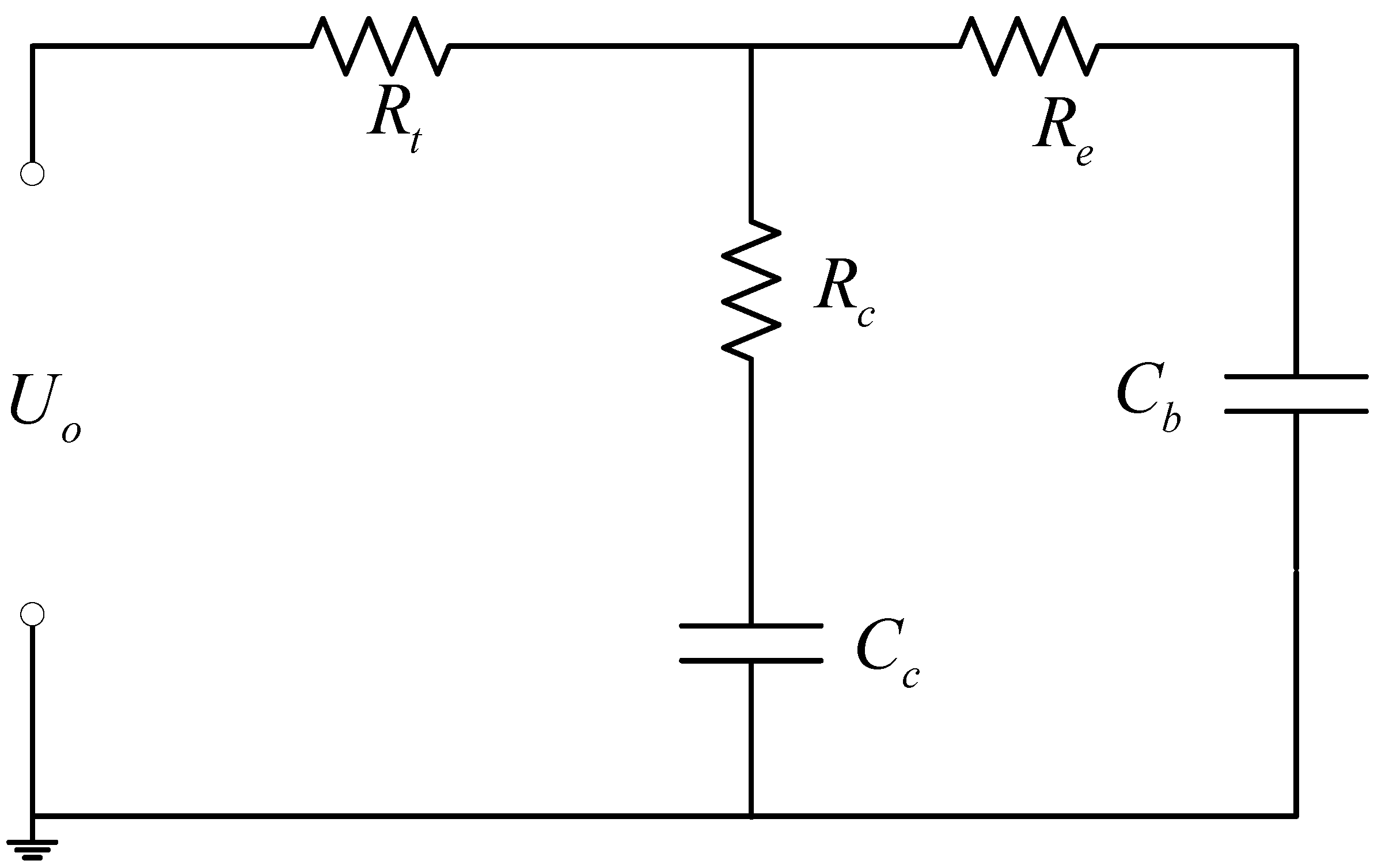
2.1. Battery Model

As shown in Figure 1, the RC battery model in ADVISOR consists of two capacitors (Cc, Cb) and three resistors (Rt, Re, Rc). The capacitor Cc is called surface capacitor, which has a small capacitance and mostly represents the surface effects of a cell. The capacitor Cb is called bulk capacitor, which has a very large capacitance and represents the ample capability of the battery to store charge chemically. SoC can be determined by the voltage across the bulk capacitor. Resistors Rt, Re, Rc are called terminal resistor, end resistor and capacitor resistor, respectively [27].
Figure 1. Schematic of RC battery model.
Energies 03 01586 g001
The state-space equations of RC model are described as follows:
  [ U C b U C c ] = [ 1 C b ( R e + R c ) 1 C c ( R e + R c ) 1 C b ( R e + R c ) 1 C c ( R e + R c ) ] [ U C b U C c ] + [ R c C b ( R e + R c ) R e C c ( R e + R c ) ] [ I ]
[ U o ] = [ R c ( R e + R c ) R e ( R e + R c ) ] [ U C b U C c ] + [ R t R e R c ( R e + R c ) ] [ I ]
where UCb and UCc are the voltage of the bulk capacitor and the voltage of the surface capacitor, respectively. Uo and I denote the output voltage and the current, respectively. Positive current denotes the discharge process.
The observability of the RC battery model can be determined from the observability matrix Q:
Q = [ C C A C A 2 ] T
where A and C are the dynamics matrix and the output matrix in Equations (1) and (2), respectively. Since the values of parameters are not zero, the observability matrix is always of full rank.

2.2. Parameter Estimation

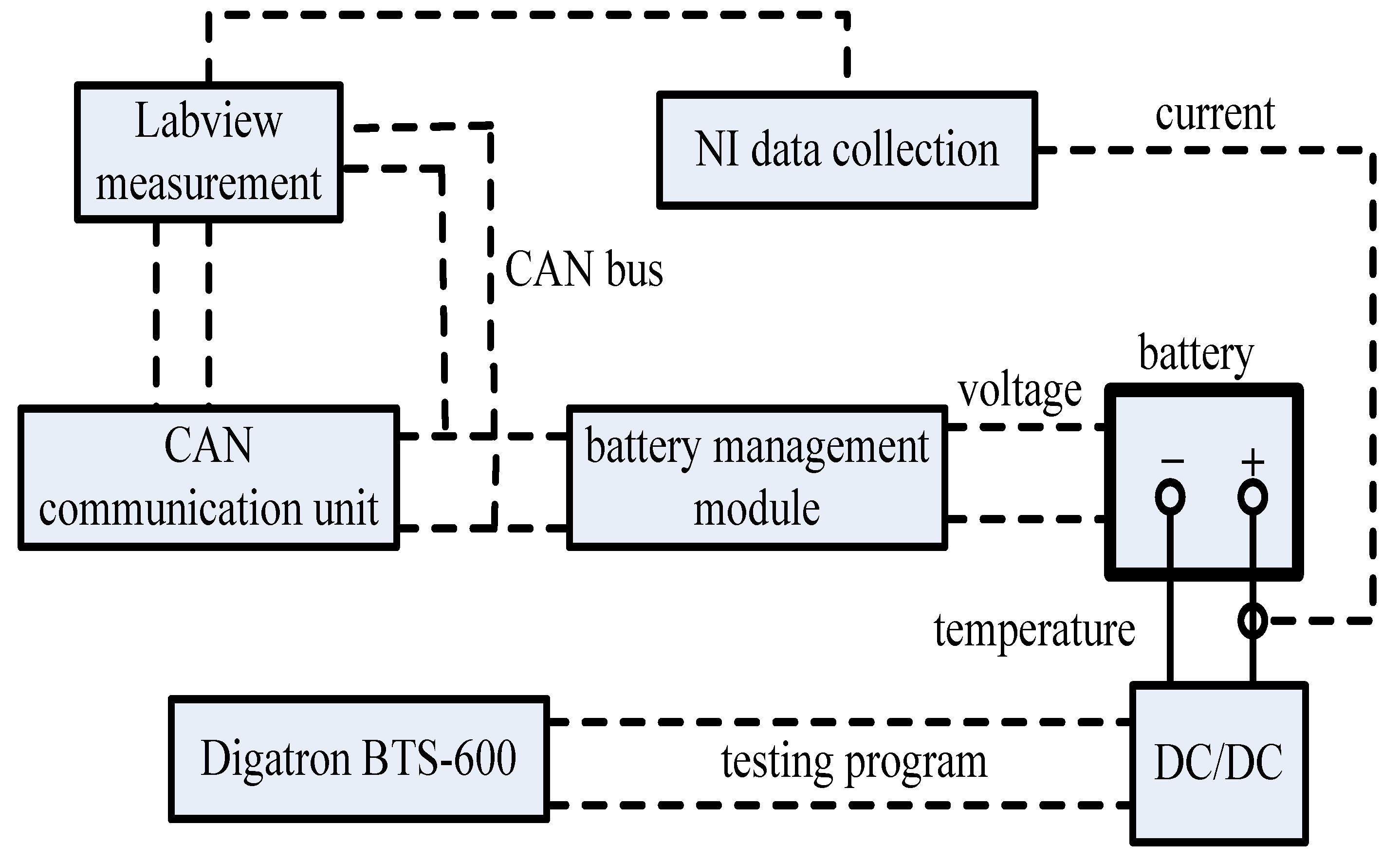
2.2.1. Battery Test Bench

As shown in Figure 2, the whole battery testing platform mainly consists of a Digatron Battery Testing System (BTS-600), a battery management module, a controller area network (CAN) communication unit and a Labview-based virtual measurement unit. The Digatron Battery Testing System is responsible for loading the battery pack based on the designed program with a maximum voltage of 500 V and maximum charging/discharging current of 500 A, while it can record many quantities, such as load current, terminal voltage, temperature, accumulative Ah and Wh. The error of the Hall current sensor is less than 0.2%. The measurement of load current is transmitted to the battery management module through a CAN bus driven by the program in Labview. The management module is able to directly collect the voltage and temperature of each cell in the pack. Both the Labview-based measurement unit and the management module have low-pass filtering programs to implement large noise cancellation. Based on the load current, voltage and temperature, the battery management module can estimate online the states of the battery pack, according to different algorithms. Here, a lithium-ion battery pack composed of sixteen cells in series for electric vehicles was used for experimentation. Each healthy cell has a nominal voltage of 3.6 V and a nominal capacity of 105 Ah.
Figure 2. Configuration of battery test bench.
Energies 03 01586 g002

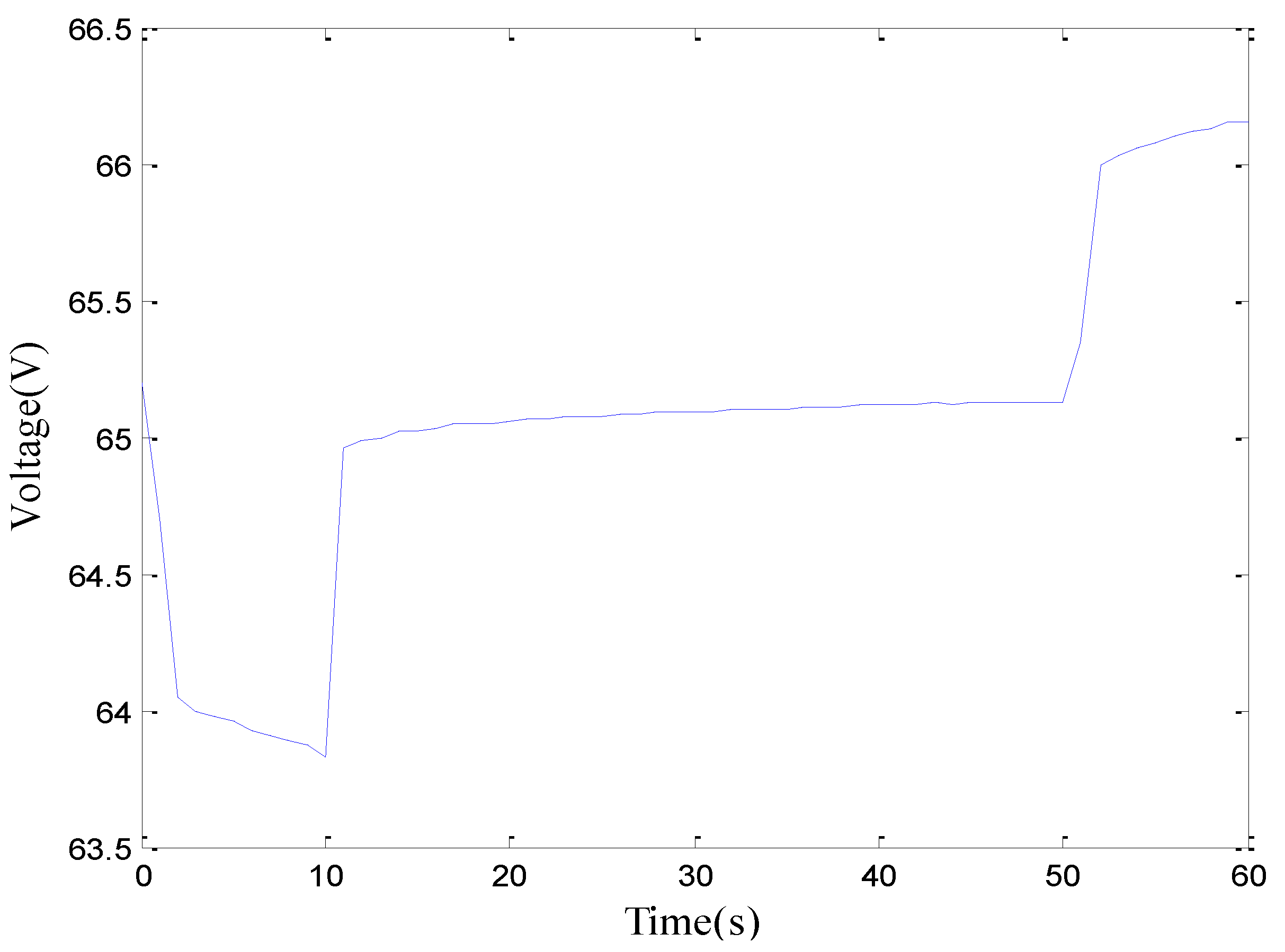
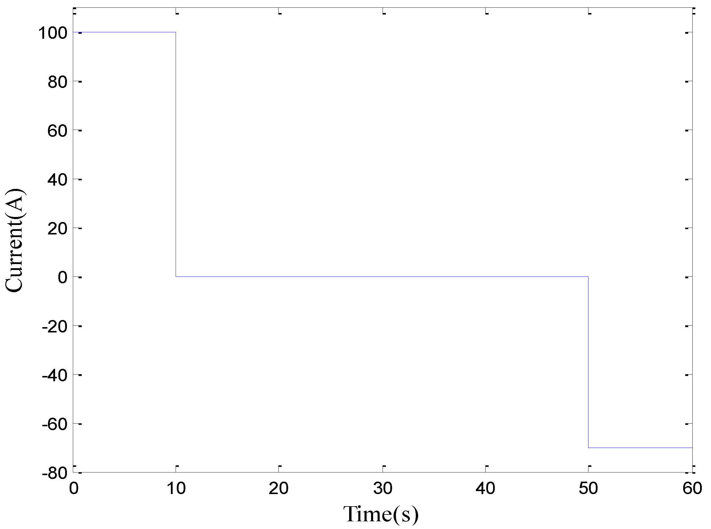
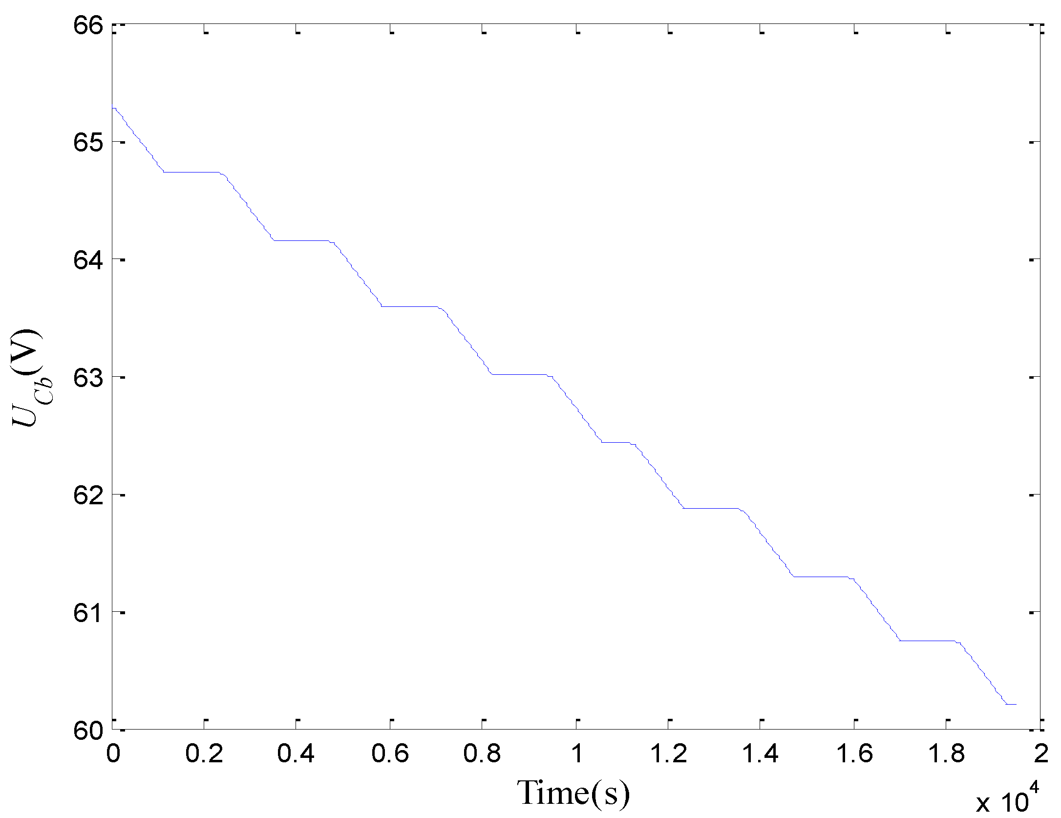
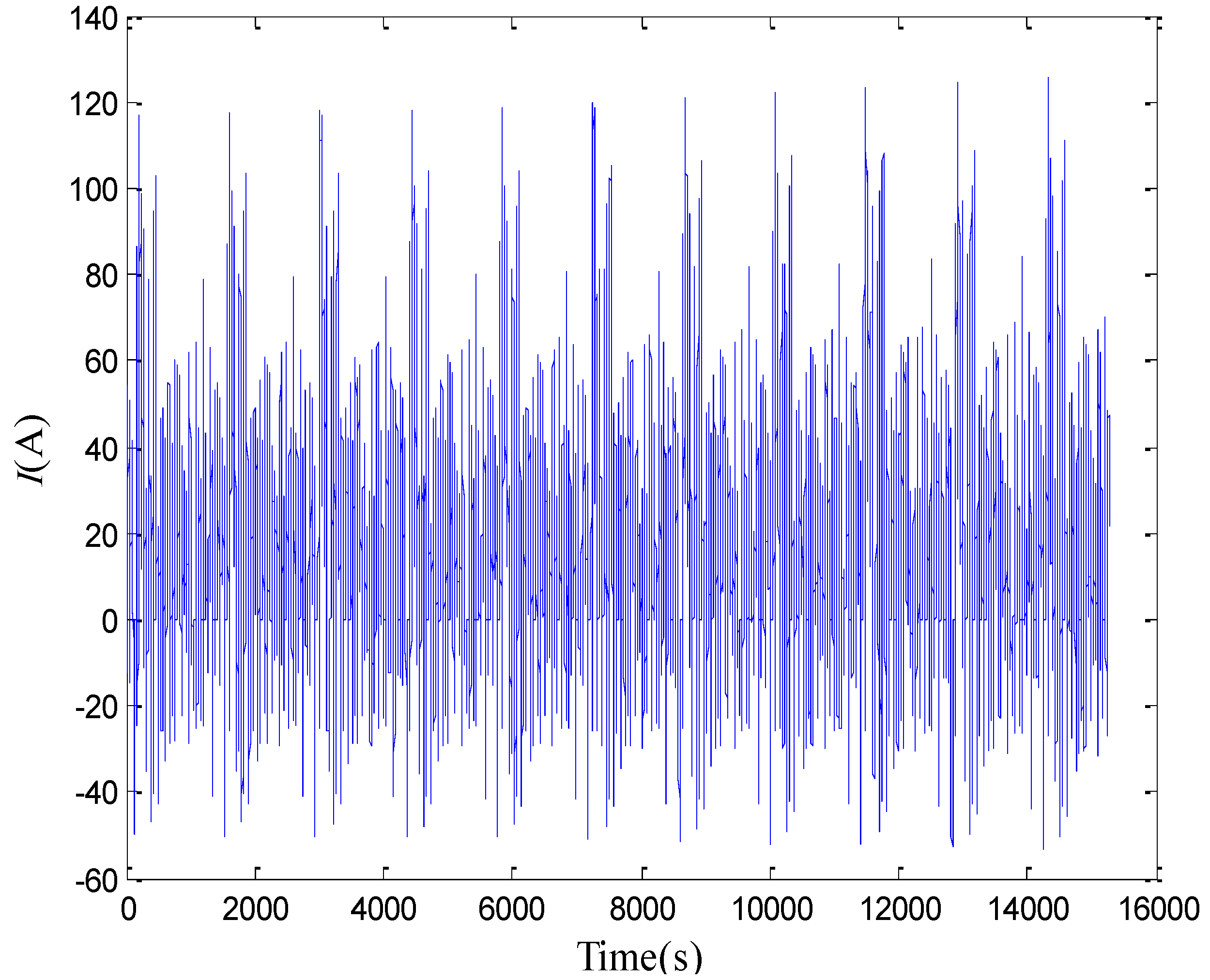
2.2.2. Acquisition of Estimation Data

In order to collect estimation data for identifying model parameters, a Hybrid Pulse Power Characterization (HPPC) test was conducted for the lithium-ion battery pack at each 10% SoC decrement in the range from 90% to 10%, where temperature was controlled within 25 ± 2 °C. One HPPC test profile is shown in Figure 3. At 90% SoC, the battery voltage profile is shown in Figure 4.
Figure 3. A single HPPC test profile.
Energies 03 01586 g003
Figure 4. Battery voltage profile in HPPC test at 90% SoC.
Energies 03 01586 g004

2.2.3. Determination of Initial Model Parameters

According to the method provided in the guide document in ADVISOR [27], the data in HPPC testing profiles was used to determine the initial values of the five unknown parameters (Cc, Cb, Rt, Re, Rc). The results are shown in Table 1. Herein, the initial value of Cb is assumed to be independent of SoC, which is a simplification for determining Cb [5,24,27].
Table 1. Initial parameters of the battery model.
SoCCb (F)Cc (F)Re (Ω)Rc (Ω)Rt (Ω)
0.95236065.040.00910.00910.00445
0.85236074.560.00880.00880.00440
0.75236074.510.00860.00860.00432
0.65236068.370.00870.00870.00425
0.55236063.140.00870.00870.00425
0.45236050.900.00900.00900.00434
0.35236047.930.00910.00910.00445
0.25236046.440.00920.00920.00448
0.15236045.320.00950.00950.00453

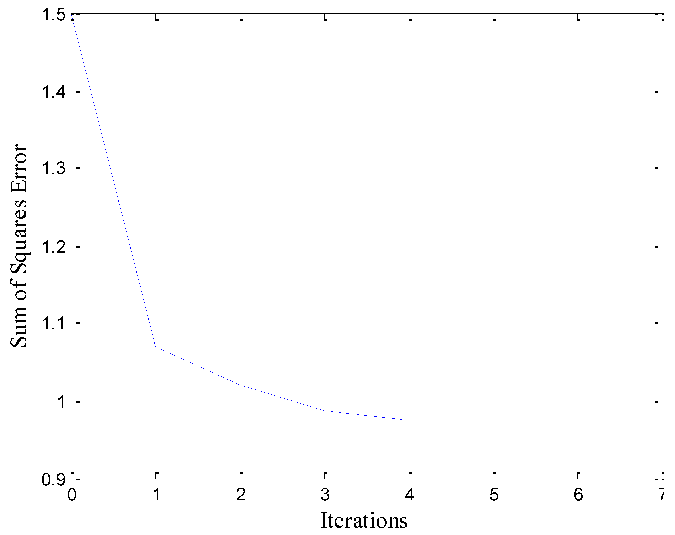
2.2.4. Optimization of Model Parameters

At each 10% SoC decrement from 90% to 10%, the numerically nonlinear least squares algorithm is run based on the battery model in equation (1) in Simulink with a ±15% deviation in these initial parameters to find the best fit with the objective to minimize the sum of squares voltage error over the corresponding HPPC profile. For example, at 90% SoC, the change of the cost function during the optimization is shown in Figure 5. It can be seen that the optimization drops the sum of squares error by 35%. The trajectories of the five parameters are shown in Figure 6. Figure 7 shows the performance of the optimized battery model over the HPPC test data at 90% SoC. The associated relative voltage error is shown in Figure 8. The average relative error is 0.13% and the relatively bigger error appears when the battery pack is loaded suddenly.
The optimized values of the five parameters over other HPPC profiles can also be obtained using the same method. The optimized parameters at each 10% SoC decrement in the range from 90% to 10% are shown in Table 2. It is noticeable that the optimized value of the bulk capacitor can still be viewed as independent of SoC.
Figure 5. Cost function of Optimization.
Energies 03 01586 g005

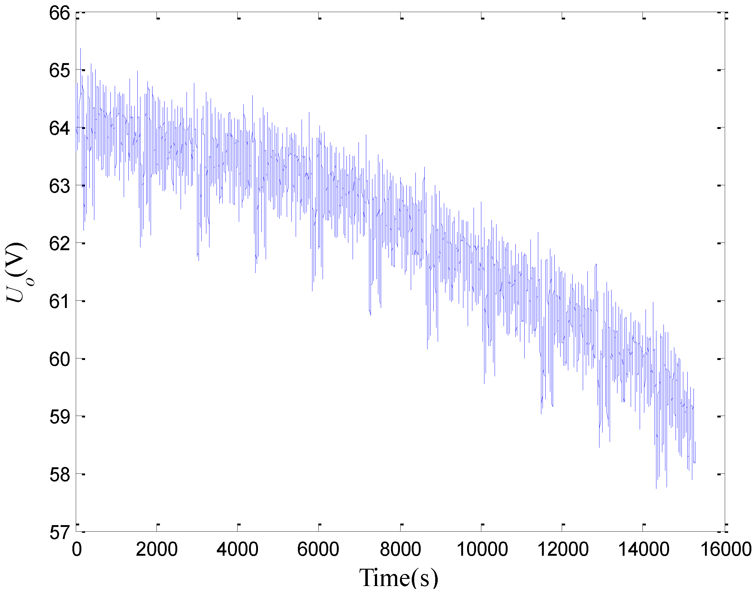
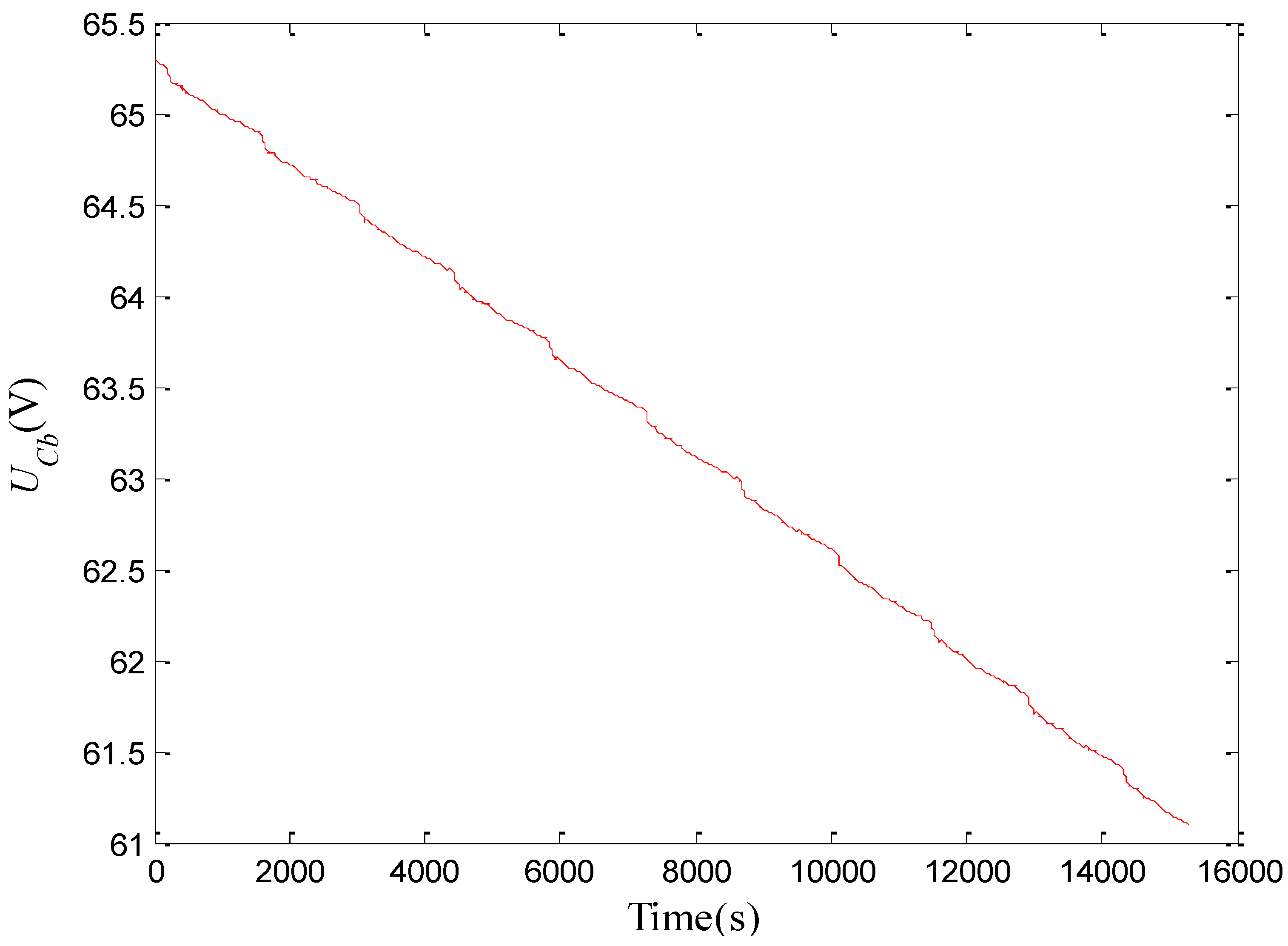
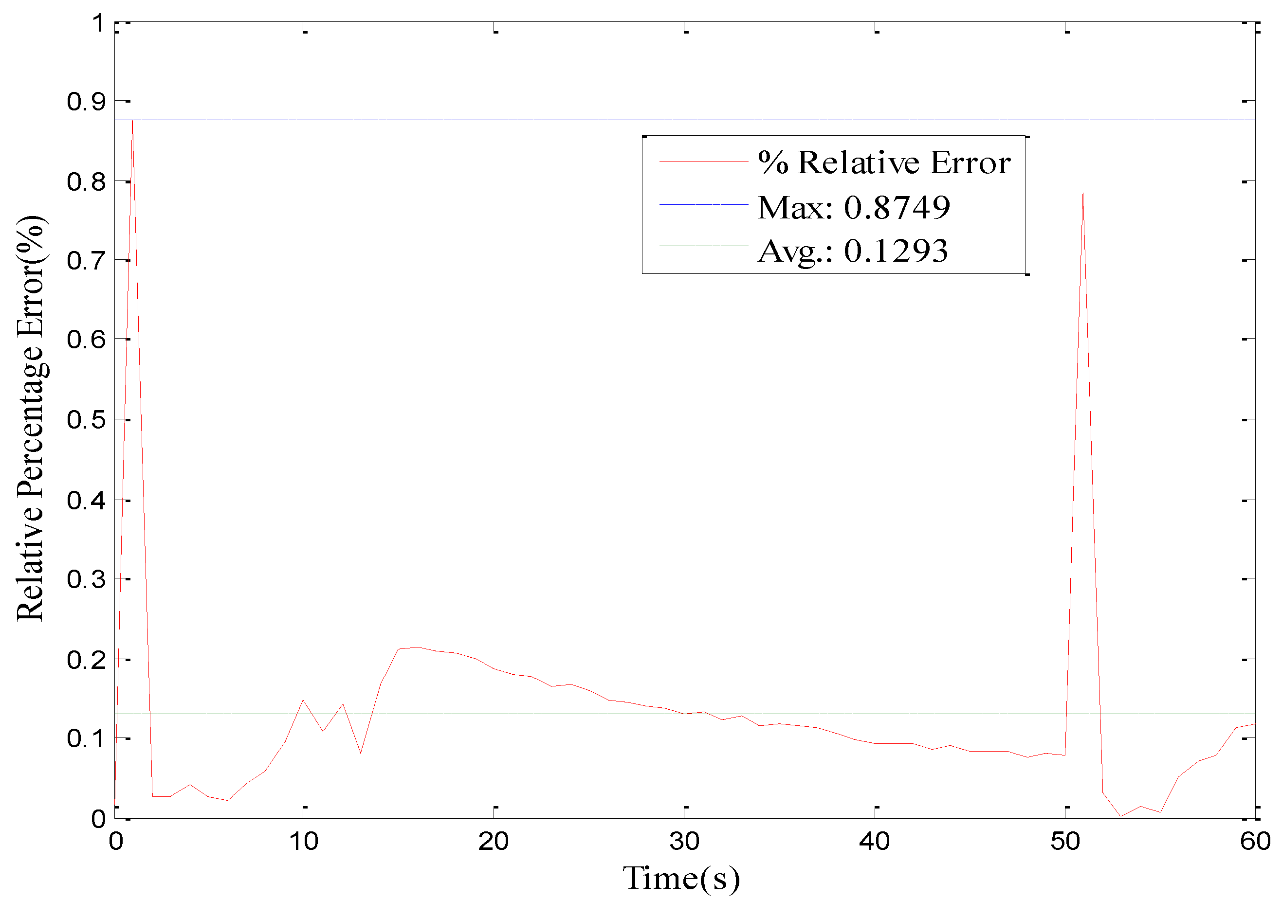
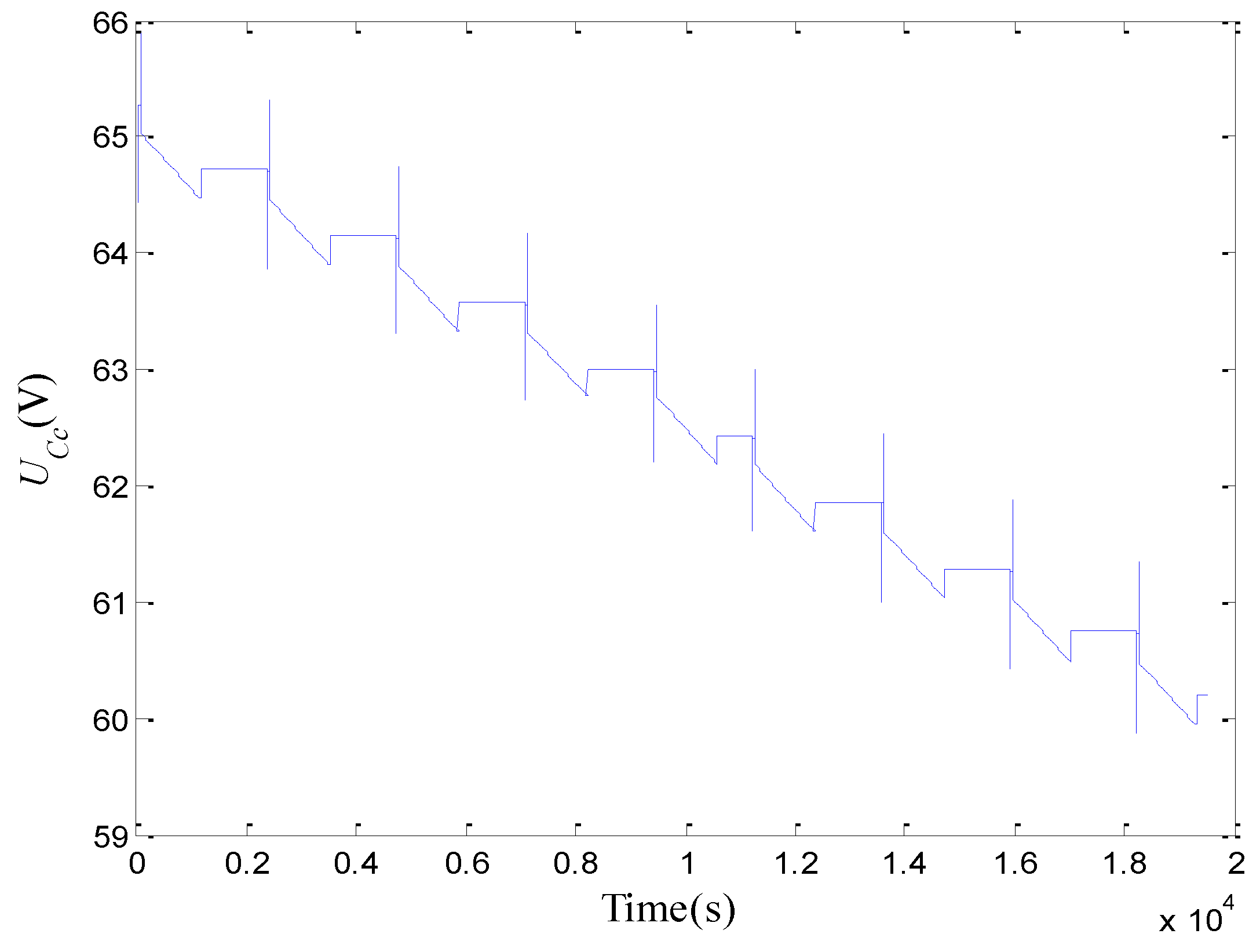
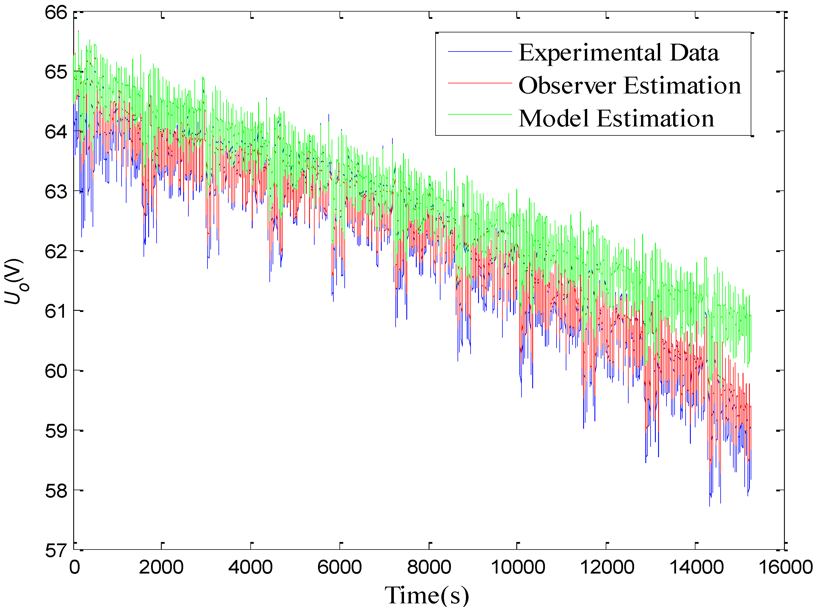
2.2.5. Model Evaluation

In order to evaluate the validity of the optimized model, a testing cycle including HPPC profiles as shown in Figure 9 was used to excite both the lithium-ion battery pack and the battery model. The initial SoC is 0.9. The parameters of the battery model as a function of SoC are updated via linear table lookup and extrapolation. The results are given in Figure 10. It is clear that the underlying dynamic characteristics of the battery pack and the model are essentially the same. The average absolute and relative errors are 0.269 V and 0.45%, respectively. As shown in Figure 11, the voltage across the bulk capacitor during the rest of the battery pack is basically unchanged due to a very large capacitance with the function of storing the energy of the battery pack. From Figure 12, it is obvious that the voltage across the surface capacitor with a small capacitance has a more dynamical change, from which it can be known that the surface capacitor is mainly responsible for simulating dynamic behaviors of the battery pack. A drift exists when the model is in an open-loop state over a long time.
Figure 6. Trajectories of the five parameters.
Energies 03 01586 g006
Figure 7. Performance of the optimized battery model in HPPC test at 90% SoC.
Energies 03 01586 g007
Figure 8. Relative error of the optimized battery model in HPPC test at 90% SoC.
Energies 03 01586 g008
Table 2. Optimized parameters of the battery model.
SoCCb (F)Cc (F)Re (Ω)Rc (Ω)Rt (Ω)
0.95800271.550.008540.008190.00409
0.85800282.010.008480.008120.00396
0.75800281.970.008400.008030.00394
0.65800275.200.008320.007950.00392
0.55800269.450.007830.007830.00391
0.45800255.990.008410.008100.00405
0.35800252.730.008510.008190.00410
0.25800251.090.008620.008220.00416
0.15800250.120.008680.008250.00416
Figure 9. A testing cycle for evaluating the validity of the battery model.
Energies 03 01586 g009
Figure 10. Voltage response of the battery model.
Energies 03 01586 g010
Figure 11. Modeled voltage across the bulk capacitor.
Energies 03 01586 g011
Figure 12. Modeled voltage across the surface capacitor.
Energies 03 01586 g012

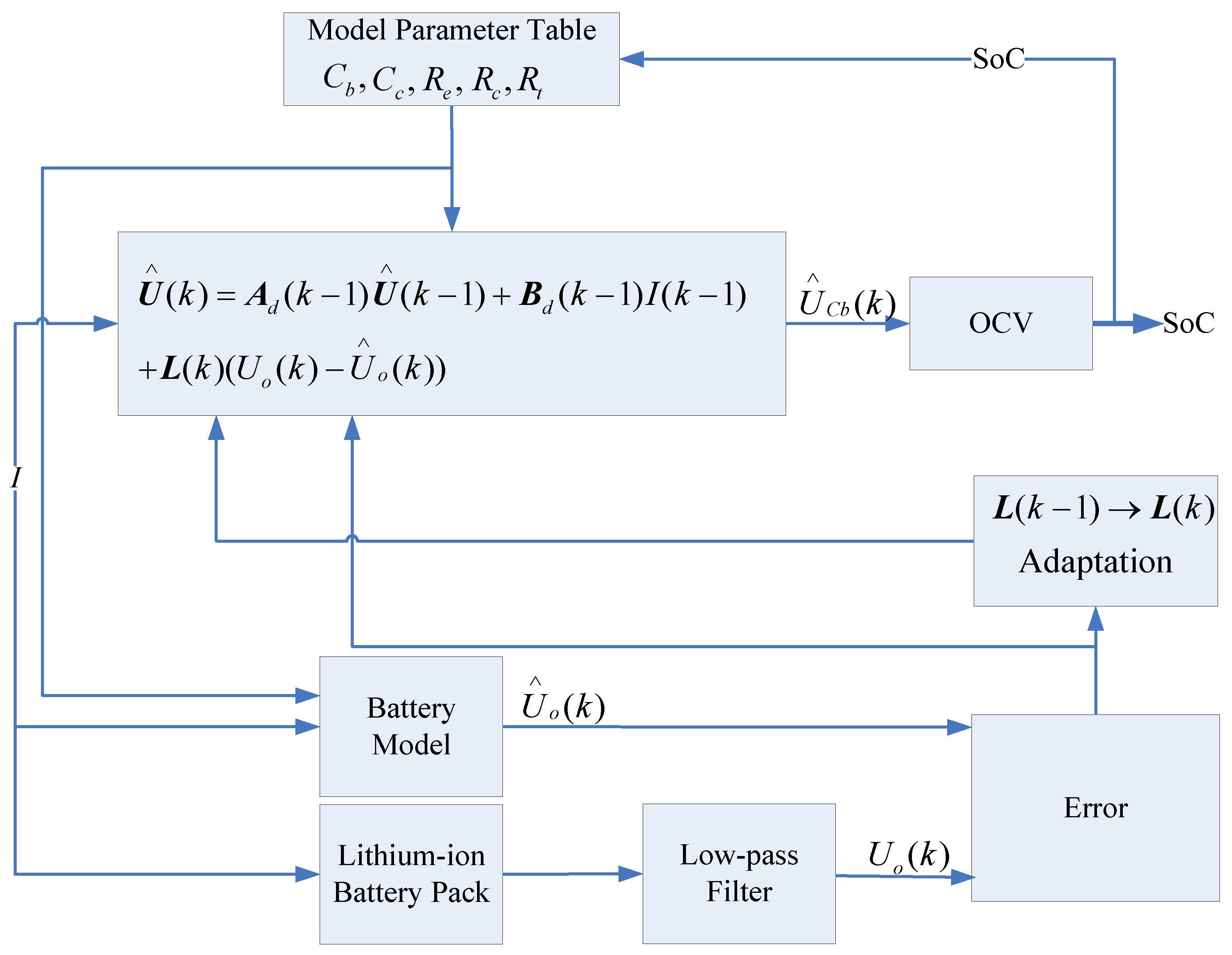
3. SoC Estimation Using Adaptive Luenberger Observer

From the analysis of the validity of the battery model, it can be seen that a drift appears when the model is in an open-loop state for a long time. This effect would be more obvious if the error in the initial condition and unknown disturbances exist. Therefore, here an adaptive Luenberger observer by means of the optimized battery model is applied in a closed-loop form to estimate SoC of the lithium-ion battery pack in electric vehicle driving cycles.

3.1. The Adaptive Luenberger Observer

The so-called Luenberger observer was firstly proposed to tackle state estimation for linear deterministic dynamic systems [28]. There also have been many studies on extended Luenberger observer design for nonlinear and time-varying systems [29,30,31]. Many analytical methods were applied to design the observer gains for linear and nonlinear deterministic systems [29,30,31]. In order to be valid and suitable for state estimation of nonlinear stochastic dynamical systems, an adaptive extended Luenberger observer in a prediction form was proposed, where the observer gain can be in real time updated to minimize MSE between the measurement and estimated output at each step [32]. Here, this technique is extended to a filtering form and illustrated as follows. In the notation we use, the decoration “circumflex” represents an estimated quantity.
Consider a nonlinear and time-varying stochastic dynamical system (MISO) described by:
x ( k + 1 ) = f ( x ( k ) , u ( k ) , k ) + ω ( k )
y ( k ) = g ( x ( k ) , u ( k ) , k ) + ν ( k )
where ω(k) and ν(k) are the process noise and the measurement noise, respectively.
The adaptive Luenberger observer in a filtering form is specified by:
x ( k ) = f ( x ( k 1 ) , u ( k 1 ) , k 1 ) + L ( k ) [ y ( k ) y ( k ) ]
y ( k ) = g ( x ( k / k 1 ) , u ( k ) , k )
where x (k/k-1) denotes the state estimate in time update and L(k) is the observer gain.
Suppose L(k) is updated adaptively such that MSE along a given training trajectory { u ( k ) , y ( k ) } k = 1 N is minimized. Instead of using batch training, the stochastic gradient approach proposed by Widrow [33,34], is adopted to implement the adaptive mechanism as follows:
J = [ y ( k ) y ( k ) ] T [ y ( k ) y ( k ) ]
J L = 2 [ y ( k ) y ( k ) ] T g x ( x ( k / k 1 ) , u ( k ) , k ) x ( k / k 1 ) L
x ( k / k 1 ) L = f x ( x ( k 1 ) , u ( k 1 ) , k 1 ) x ( k 1 ) L
L ( k ) = L ( k 1 ) η J L
x ( k ) L = [ I L ( k ) g x ( x ( k / k 1 ) , u ( k ) , k ) ] f x ( x ( k 1 ) , u ( k 1 ) , k 1 ) x ( k 1 ) L + [ y ( k 1 ) y ( k 1 ) ] [ 1 ] n × n ,
where fx(.) and gx(.) represent the Jacobians of the corresponding functions with respect to the state vector, [1]n×n denotes an all-ones square matrix of the size of the state vector, and η is the learning rate.

3.2. SoC Estimation Algorithm Based on the Optimized Battery Model

Given the battery model in Equations (1) and (2), the stochastic process to be estimated is described by the following equations:
U ( k + 1 ) = A d ( k ) U ( k ) + B d ( k ) I ( k ) + ω ( k )
U o ( k ) = C ( k ) U ( k ) + D ( k ) I ( k ) + ν ( k )
where U(k) represents the voltage vector for the bulk and surface capacitors, Uo(k) is the output voltage:
A d ( k ) A ( k ) Δ t + [ 1 0 0 1 ]
B d ( k ) B ( k ) Δ t
and A(k), B(k), C(k) and D(k) are the dynamics matrix, the input matrix, the measurement matrix and the feedthrough matrix in Equations (1) and (2) at the time k, respectively. Δt is the sampling period.
The equations of adaptive Luenberger observer based on Equations (13) and (14), are described by:
L ( k ) = L ( k 1 ) + 2 η [ U o ( k ) U o ( k ) ] C ( k 1 ) A d ( k 1 ) U ( k 1 ) L
U ( k ) = A d ( k 1 ) U ( k 1 ) + B d ( k 1 ) I ( k 1 ) + L ( k ) [ U o ( k ) U o ( k ) ]
U ( k ) L = [ A d ( k 1 ) L ( k ) C ( k 1 ) A d ( k 1 ) ] U ( k 1 ) L + [ U o ( k ) U o ( k ) ] [ 1 ] n × n
It is obvious that the computation cost is low, since there is no matrix inversion in the observer equations for the battery model. Additionally, as the battery model is observable and linear time-invariant in one sample interval, a globally asymptotically stable observer can be achieved [32]. The schematic configuration of SoC estimation of the battery pack is shown in Figure 13. The charging/discharging current is applied to the lithium-ion battery pack and the battery model simultaneously. MSE between the estimated battery voltage and the filtered battery voltage measurement is reduced by adaptively updating the observer gain. Then the observer with the updated gain is used to compensate for the state estimation error. SoC is determined by the estimated voltage of the bulk capacitor U Cb, based on the open-circuit voltage (OCV) profile of the battery pack. The estimate of SoC is then fed back to update the parameters of the battery model for the next SoC estimation.
Figure 13. Adaptive observer based SoC estimation.
Energies 03 01586 g013

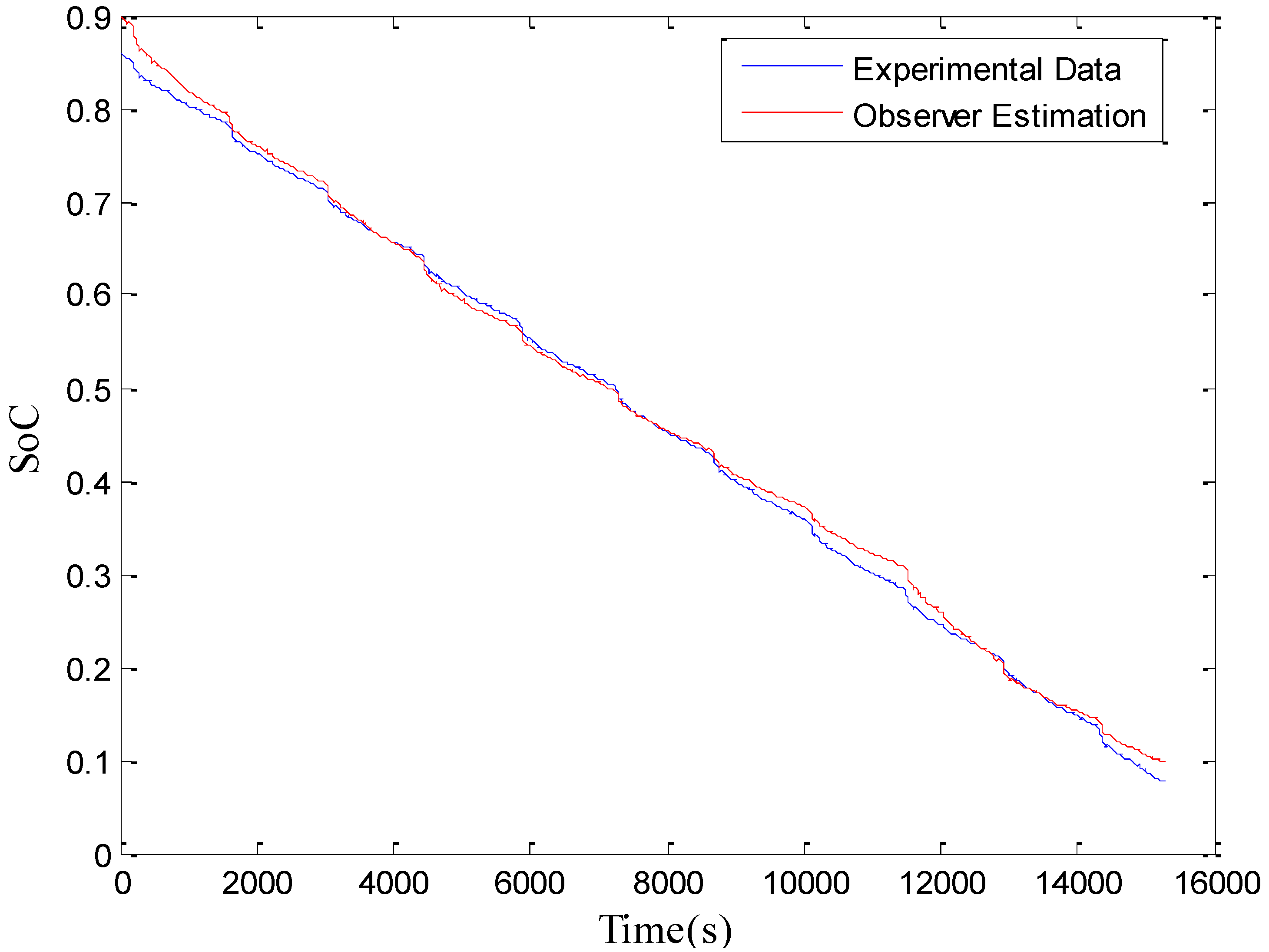
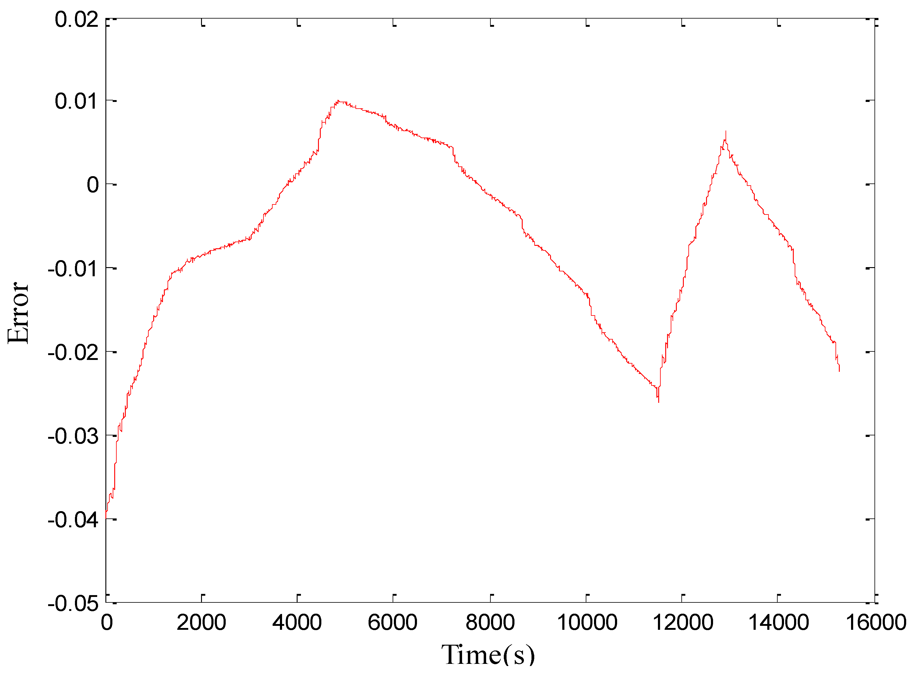
3.3. SoC Estimation Result

The Federal Urban Driving Schedules (FUDS) cycle is a typical working cycle that is often used to evaluate various SoC estimation algorithms [10,11,12,19,28]. Therefore, in the battery testing bench as described in Section 2.2.1, the FUDS test for the lithium-ion battery pack was conducted to validate the proposed SoC estimation method. The voltage and current profiles sampled during eleven consecutive FUDS cycles are shown in Figure 14 and Figure 15, respectively. The initial parameters for the adaptive observer were specified as follows:
U ( 0 ) = [ 65.3 ; 65.3 ]
L ( 0 ) = [ - 0.0001 ; - 0.0002 ]
x ( 0 ) L = [ 0 ] 2 × 2
η = 0.0001
where [0]2×2 represents an all-zeros square matrix of the size of 2. The initial SoC is intentionally specified to be 0.9, deviating from the true value of 0.86, in order to better evaluate the validity of the algorithm.
Figure 14. Battery terminal voltage measurement during FUDS cycles.
Energies 03 01586 g014
Figure 15. Battery current measurement during FUDS cycles.
Energies 03 01586 g015
The results of the estimation of the output voltage are shown in Figure 16. It is clear that the model in an open-loop state has an obvious drift due to the error of the initial SoC value. Nevertheless, the adaptive observer can be effective to correct the drift so that the estimate of the output voltage in a closed-loop state has a superior performance. It illustrates that the adaptive observer based estimator in a closed-loop form is more robust to the error of the initial condition and some unknown disturbances, compared to the battery model in an open loop. The average absolute and relative errors are 0.1455 V and 0.24%, respectively. The result of the estimation of the voltage of the bulk capacitor is shown in Figure 17. The estimate of SoC is shown in Figure 18. The experimental values of SoC were obtained by Coulomb counting in a well-controlled experimental condition, taking the Coulombic efficiency into account. The estimation error is shown in Figure 19. It is notable that the absolute error can quickly be within 2.5%.
Figure 16. Estimation of the battery terminal voltage.
Energies 03 01586 g016
Figure 17. Estimation of the voltage of the bulk capacitor.
Energies 03 01586 g017
Figure 18. Performance of SoC estimation.
Energies 03 01586 g018
Figure 19. SoC estimation error.
Energies 03 01586 g019

4. Conclusions

In this paper, an adaptive Luenberger observer is applied to estimate SoC of a traction lithium-ion battery pack based on an optimized RC battery model. The numerically nonlinear least squares algorithm is used to identify and optimize the parameters of the battery model as a function of SoC. The observer gain is updated using a stochastic gradient approach to reduce MSE between the estimated voltage and the measurement. Validation results show that the absolute SoC estimation error can quickly converge into a favorable range within 2.5% and the estimator is robust to the error of the initial condition and unknown disturbances with a low computational cost and has no requirement for knowing and specifying a priori characteristics of the process noise and the measurement noise.

Acknowledgements

We would like to express our deep gratitude to Huei Peng in The University of Michigan for many helpful discussions. This work was supported by the National Natural Science Foundation of China (50905015) and the National High Technology Research and Development Program of China (2003AA501800).

References

  1. Piller, S.; Perrin, M.; Jossen, A. Methods for state-of-charge determination and their applications. J. Power Sources 2001, 96, 113–120. [Google Scholar] [CrossRef]
  2. Aylor, J.H.; Johnson, B.W. A battery state-of-charge indicator for electric wheelchairs. IEEE Trans. Ind. Electron. 1992, 39, 398–409. [Google Scholar] [CrossRef]
  3. Liu, T.H.; Chen, D.F.; Fang, C.C. Design and implementation of a battery charger with a state-of-charge estimator. Int. J. Electron. 2000, 87, 211–226. [Google Scholar] [CrossRef]
  4. Çadırcı, Y.; Özkazanç, Y. Microcontroller-based on-line state-of-charge estimator for sealed lead-acid batteries. J. Power Sources 2004, 129, 330–342. [Google Scholar] [CrossRef]
  5. Bhangu, B.S.; Bentley, P.; Stone, D.A.; Bingham, C.M. Nonlinear observers for predicting state-of-charge and state-of-health of lead-acid batteries for hybrid-electric vehicles. IEEE Trans. Veh. Tech. 2005, 54, 783–794. [Google Scholar] [CrossRef]
  6. Chan, C.C.; Lo, E.W.C.; Shen, W. The available capacity computation model based on artificial neural network for lead-acid batteries in electrical vehicles. J. Power Sources 2000, 87, 201–204. [Google Scholar] [CrossRef]
  7. Shen, W.X.; Chan, C.C.; Lo, E.W.C.; Chau, K.T. A new battery available capacity indicator for electric vehicles using neural network. Energy Convers. Manage. 2002, 43, 817–826. [Google Scholar] [CrossRef]
  8. Shen, W.X.; Chau, K.T.; Chan, C.C. Neural network-based residual capacity indicator for nickel-metal hydride batteries in electric vehicles. IEEE Trans. Veh. Tech. 2005, 54, 1705–1712. [Google Scholar] [CrossRef]
  9. Morita, Y.; Yamamoto, S.; Lee, S. H.; Mizuno, N. On-line detection of state-of-charge in lead acid battery using radial basis function neural network. Asian J. Control 2006, 8, 268–273. [Google Scholar] [CrossRef]
  10. Shen, W.X. State of available capacity estimation for lead-acid batteries in electric vehicles using neural network. Energy Convers. Manage. 2007, 48, 433–442. [Google Scholar] [CrossRef]
  11. Cheng, B.; Bai, Z.F.; Cao, B.G. State of charge estimation based on evolutionary neural network. Energy Convers. Manage. 2008, 49, 2788–2794. [Google Scholar] [CrossRef]
  12. Wang, J.P.; Xu, L.; Guo, J.G.; Ding, L. Modelling of a battery pack for electric vehicles using a stochastic fuzzy neural network. Proc. IMechE. Part D: J. Automobile Eng. 2009, 223, 27–35. [Google Scholar] [CrossRef]
  13. Cheng, B.; Zhou, Y.L.; Zhang, J.X.; Wang, J.P.; Cao, B.G. Ni–MH batteries state-of-charge prediction based on immune evolutionary network. Energy Convers. Manage. 2009, 50, 3078–3086. [Google Scholar] [CrossRef]
  14. Salkind, A.J.; Fennie, C.; Singh, P.; Atwater, T.; Reisne, D.E. Determination of state-of-charge and state-of-health of batteries by fuzzy logic methodology. J. Power Sources 1999, 80, 293–300. [Google Scholar] [CrossRef]
  15. Chau, K.T.; Wu, K.C.; Chan, C.C.; Shen, W.X. A new battery capacity indicator for nickel-metal hydride battery powered electric vehicles using adaptive neuro-fuzzy inference system. Energy Convers. Manage. 2003, 44, 2059–2071. [Google Scholar] [CrossRef]
  16. Chau, K.T.; Wu, K.C.; Chan, C.C. A new battery capacity indicator for lithium-ion battery powered electric vehicles using adaptive neuro-fuzzy inference system. Energy Convers. Manage. 2004, 45, 1681–1692. [Google Scholar] [CrossRef]
  17. Singh, P.; Vinjamu, R.; Wang, X.P.; Reisne, D. Design and implementation of a fuzzy logic-based state-of-charge meter for Li-ion batteries used in portable defibrillators. J. Power Sources 2006, 162, 829–836. [Google Scholar] [CrossRef]
  18. Malkhandi, S. Fuzzy logic-based learning system and estimation of state of charge of lead-acid battery. Eng. Appl. Artif. Intel. 2006, 19, 479–485. [Google Scholar] [CrossRef]
  19. Hansen, T.; Wang, C.J. Support vector based battery state of charge estimator. J. Power Sources 2005, 141, 351–358. [Google Scholar] [CrossRef]
  20. Wang, J.P.; Chen, Q.S.; Cao, B.G. Support vector machine based battery model for electric vehicles. Energy Convers. Manage. 2006, 47, 858–864. [Google Scholar] [CrossRef]
  21. Shi, Q.S.; Zhang, C.H.; Cui, N.X. Estimation of battery state-of-charge using ν -support vector regression algorithm. Int. J. Auto. Tech. 2008, 9, 759–764. [Google Scholar] [CrossRef]
  22. Hu, X.S.; Sun, F.C. Fuzzy clustering based multi-model support vector regression state of charge estimator for lithium-ion battery of electric vehicle. In Proceedings of International Conference on Intelligent Human-Machine Systems and Cybernetics, Hangzhou, Zhejiang, China, 26–27 August 2009; pp. 392–396.
  23. Plett, G.L. Extended Kalman filtering for battery management systems of LiPB-based HEV battery packs-Part1: Background, Part2: Modeling and identification, Part3: State and parameter estimation. J. Power Sources 2004, 134, 252–292. [Google Scholar] [CrossRef]
  24. Vasebi, A.; Bathaee, S.M.T.; Partovibakhsh, M. Predicting state of charge of lead-acid batteries for hybrid electric vehicles by extended Kalman filter. Energy Convers. Manage. 2008, 49, 75–82. [Google Scholar] [CrossRef]
  25. Plett, G.L. Sigma-point Kalman filtering for battery management systems of LiPB-based HEV battery packs-Part 1: Introduction and state estimation, Part 2: Simultaneous state and parameter estimation. J. Power Sources 2006, 161, 1356–1384. [Google Scholar] [CrossRef]
  26. Santhanagopalan, S.; White, R.E. State of charge estimation using an unscented filter for high power lithium ion cells. Int. J. Energy Res. 2010, 34, 152–163. [Google Scholar] [CrossRef]
  27. Wipke, K. ADVISOR 3.2 Documentation; NREL: Golden, CO, USA, 2001. [Google Scholar]
  28. Luenberger, D.G. Observers for multivariable systems. IEEE Trans. Automat. Contr. 1966, 11, 190–197. [Google Scholar] [CrossRef]
  29. Zeitz, M. The extended Luenberger observer for nonlinear systems. Sys. Control Lett. 1987, 9, 149–156. [Google Scholar] [CrossRef]
  30. Elmas, C. Zelaya de la Parra H. Application of a full-order Luenberger observer for a position sensorless operation of a switched reluctance motor drive. IEE Proc. Contr. Theor. Appl. 1996, 143, 401–408. [Google Scholar]
  31. Du, T.; Stronach, P.F. Design and application of extended observers for joint state and parameter estimation in high-performance AC drives. IEE Proc. Elec. Power Appl. 1995, 142, 71–78. [Google Scholar] [CrossRef]
  32. Erdogmus, D.; Genc, A.U.; Principe, J.C. A neural network perspective to extended Luenberger observers. Inst. Meas. Control 2002, 35, 10–16. [Google Scholar] [CrossRef]
  33. Widrow, B.; Stearns, S.D. Adaptive Signal Processing; Prentice Hall: Englewood Cliffs, NJ, USA, 1985. [Google Scholar]
  34. Widrow, B.; Kamenetsky, M. On the Efficiency of Adaptive Algorithms. In Least-Mean-Square Adaptive Filters; Haykin, S., Widrow, B., Eds.; Wiley-Interscience: Hoboken, NJ, USA, 2003; pp. 1–34. [Google Scholar]

