Designing an Energy Storage System Fuzzy PID Controller for Microgrid Islanded Operation

Abstract
:1. Introduction
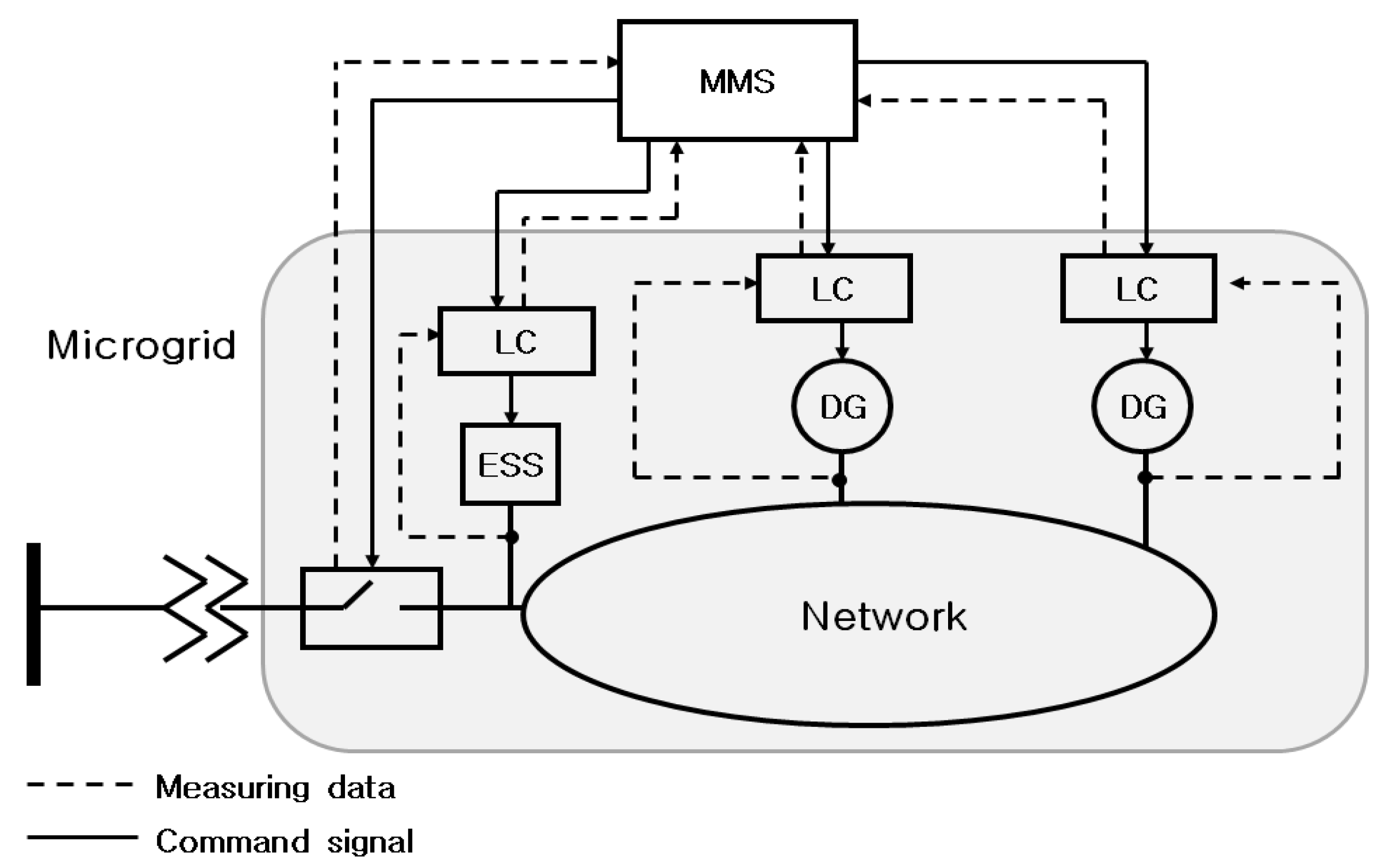
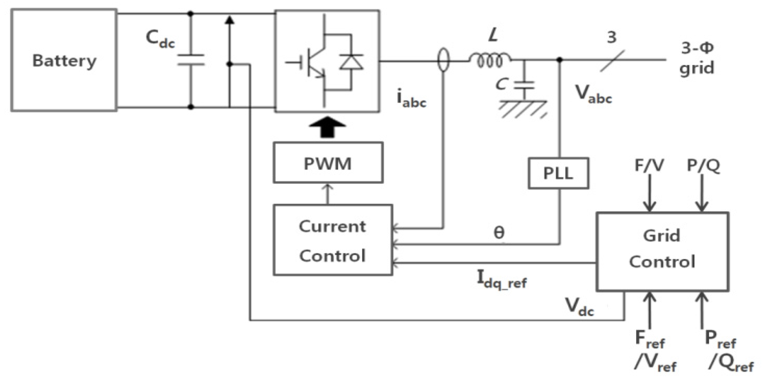
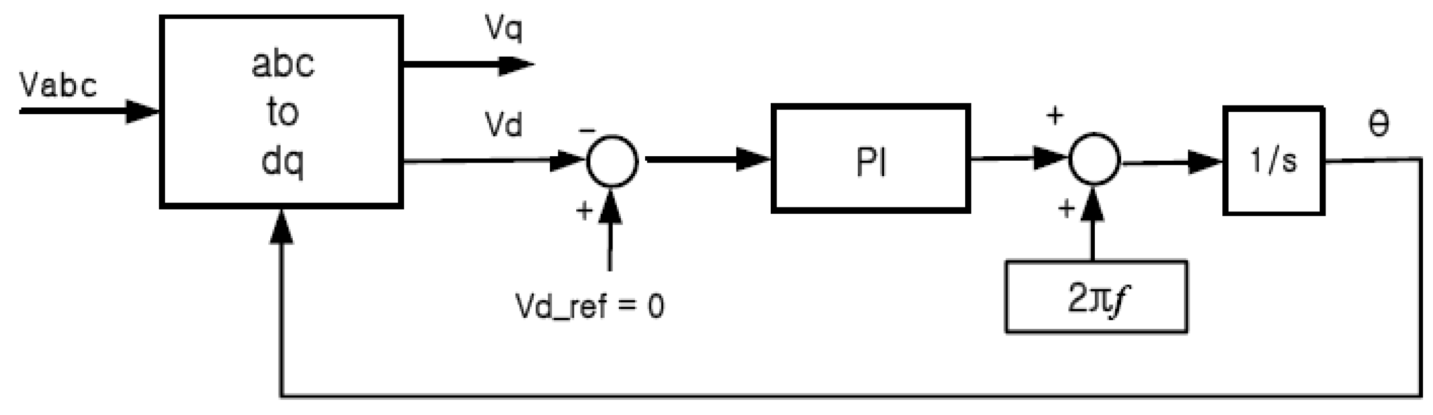
2. Microgrid Configuration

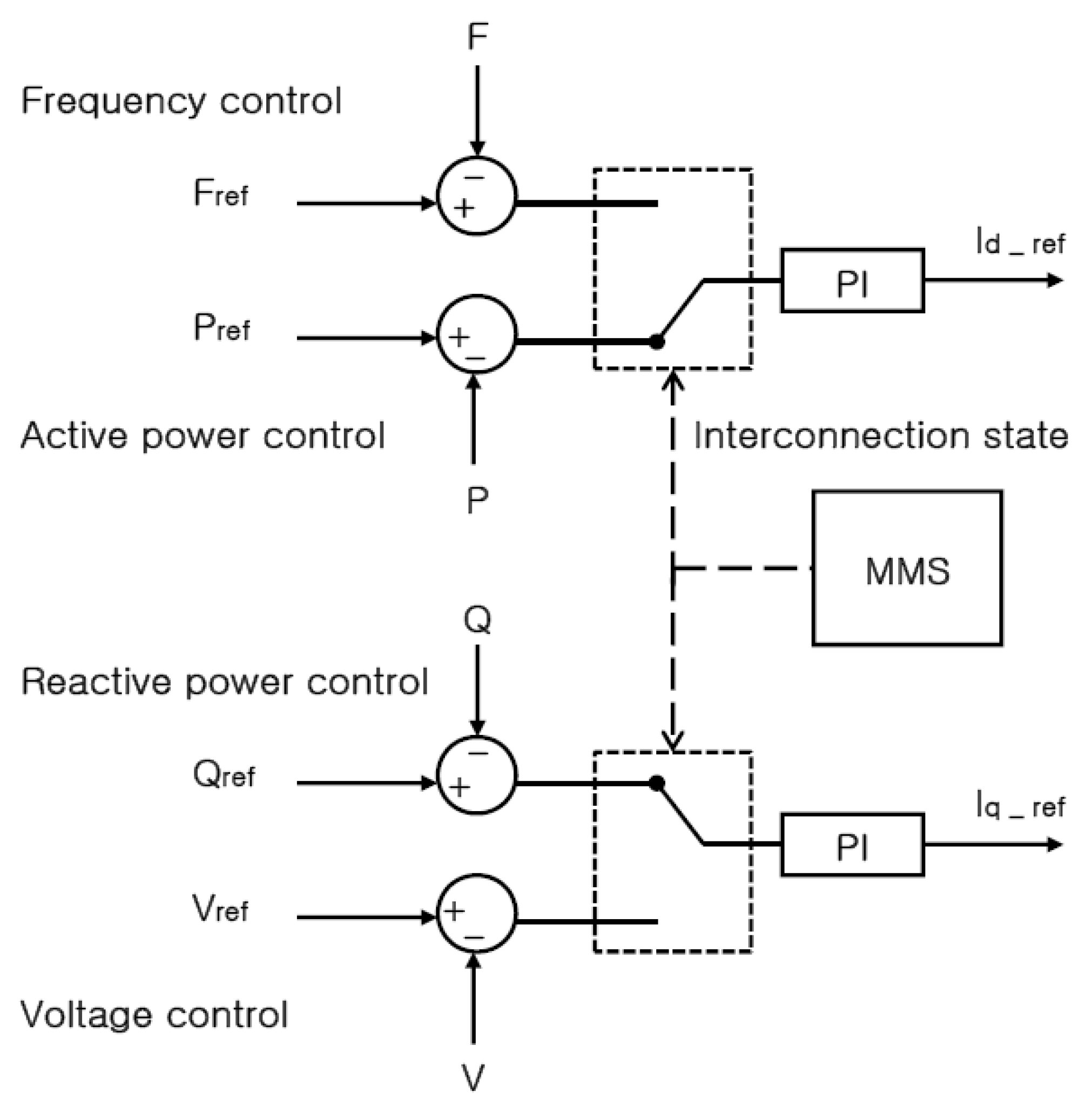
3. Control Strategy for Microgrid Islanded Operation
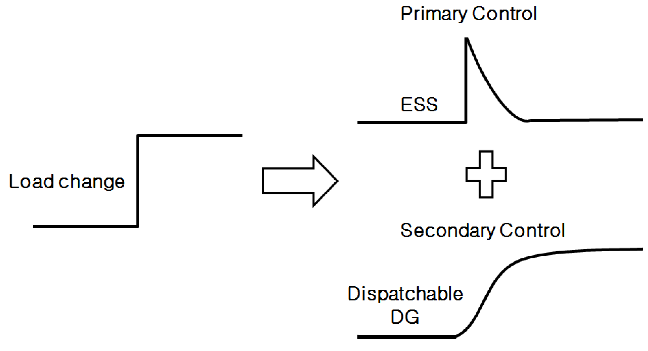
3.1. Main Concept for Islanded Operation

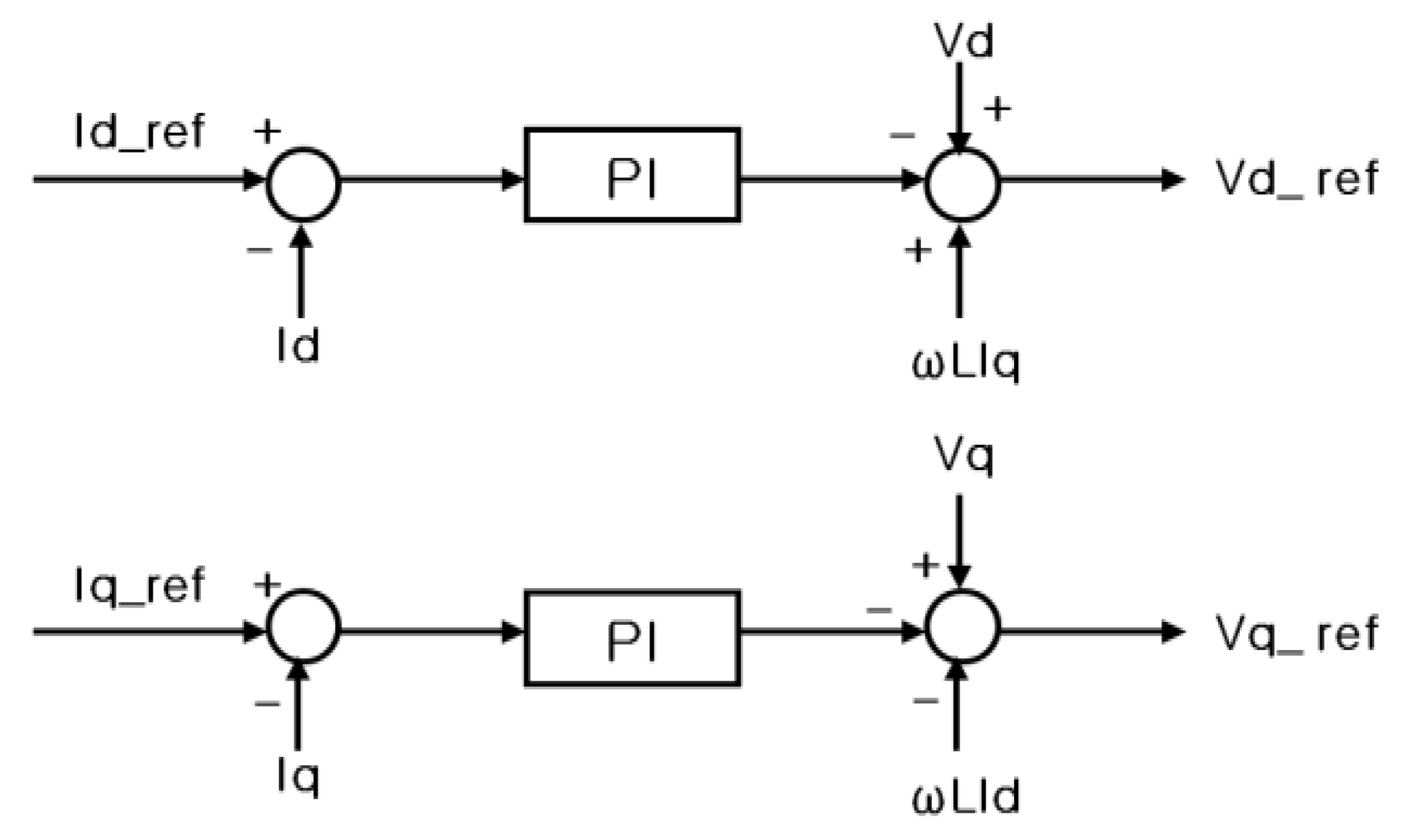
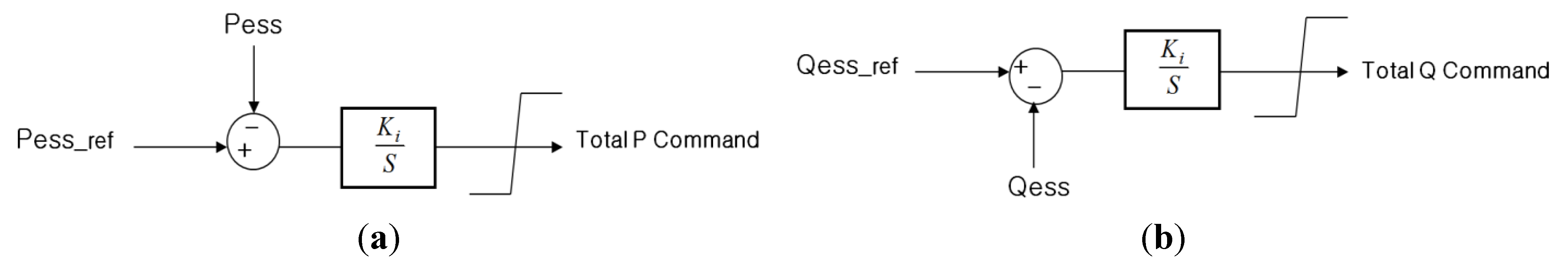
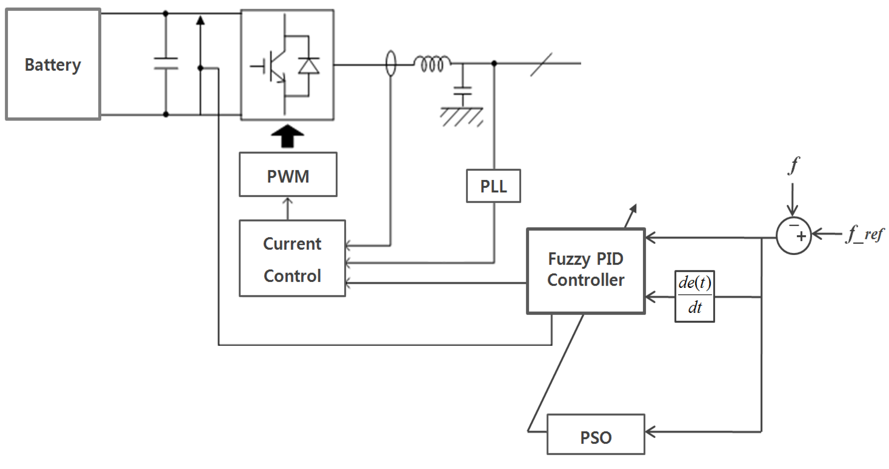
3.2. Primary Control of Energy Storage System


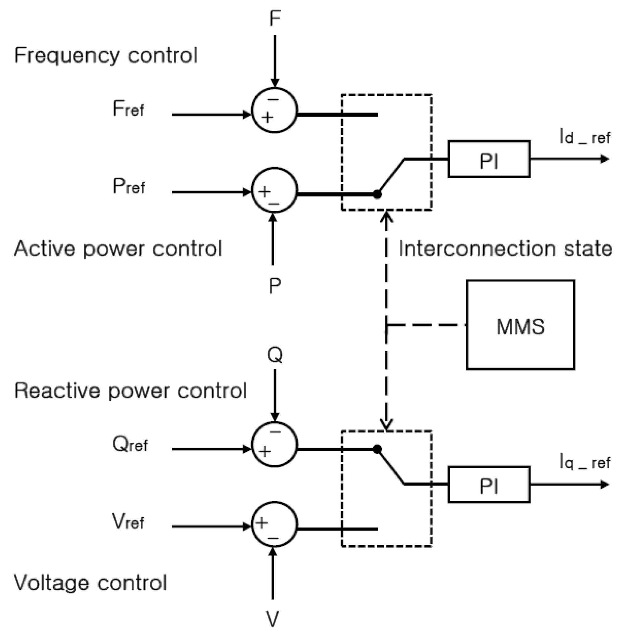

3.3. Secondary Control of MMS

4. Design of a Fuzzy Controller for an Energy Storage System
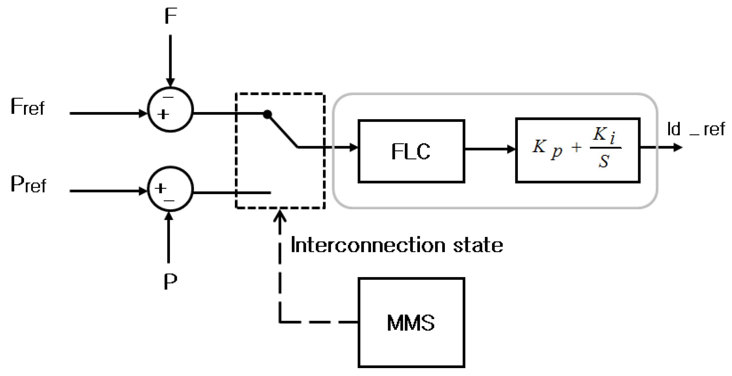
4.1. Fuzzy PID Controller
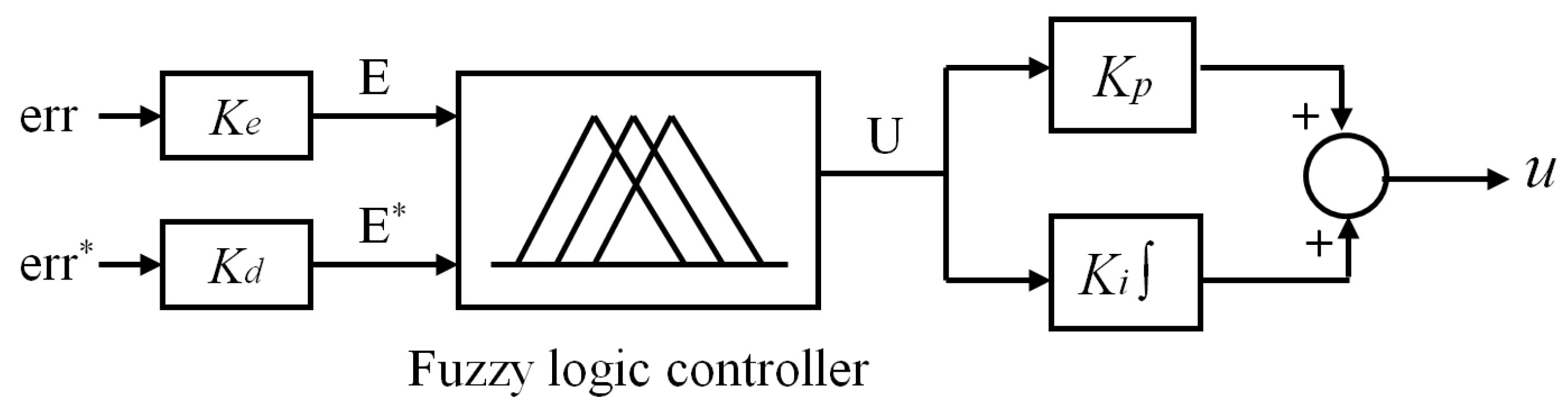
- Proportional gain: KpKeP + KiKdD
- Integral gain: KiKeP
- Derivative gain: KpKdD

| NB | NM | NS | ZO | PS | PM | PB | ||
|---|---|---|---|---|---|---|---|---|
| e | ||||||||
| NB | NB | NB | NB | NM | NM | NS | ZO | |
| NM | NB | NB | NM | NM | NS | ZO | PS | |
| NS | NB | NM | NM | NS | ZO | PS | PM | |
| ZO | NM | NM | NS | ZO | PS | PM | PM | |
| PS | NM | NS | ZO | PS | PM | PM | PB | |
| PM | NS | ZO | PS | PM | PM | PB | PB | |
| PB | ZO | PS | PM | PM | PB | PB | PB | |

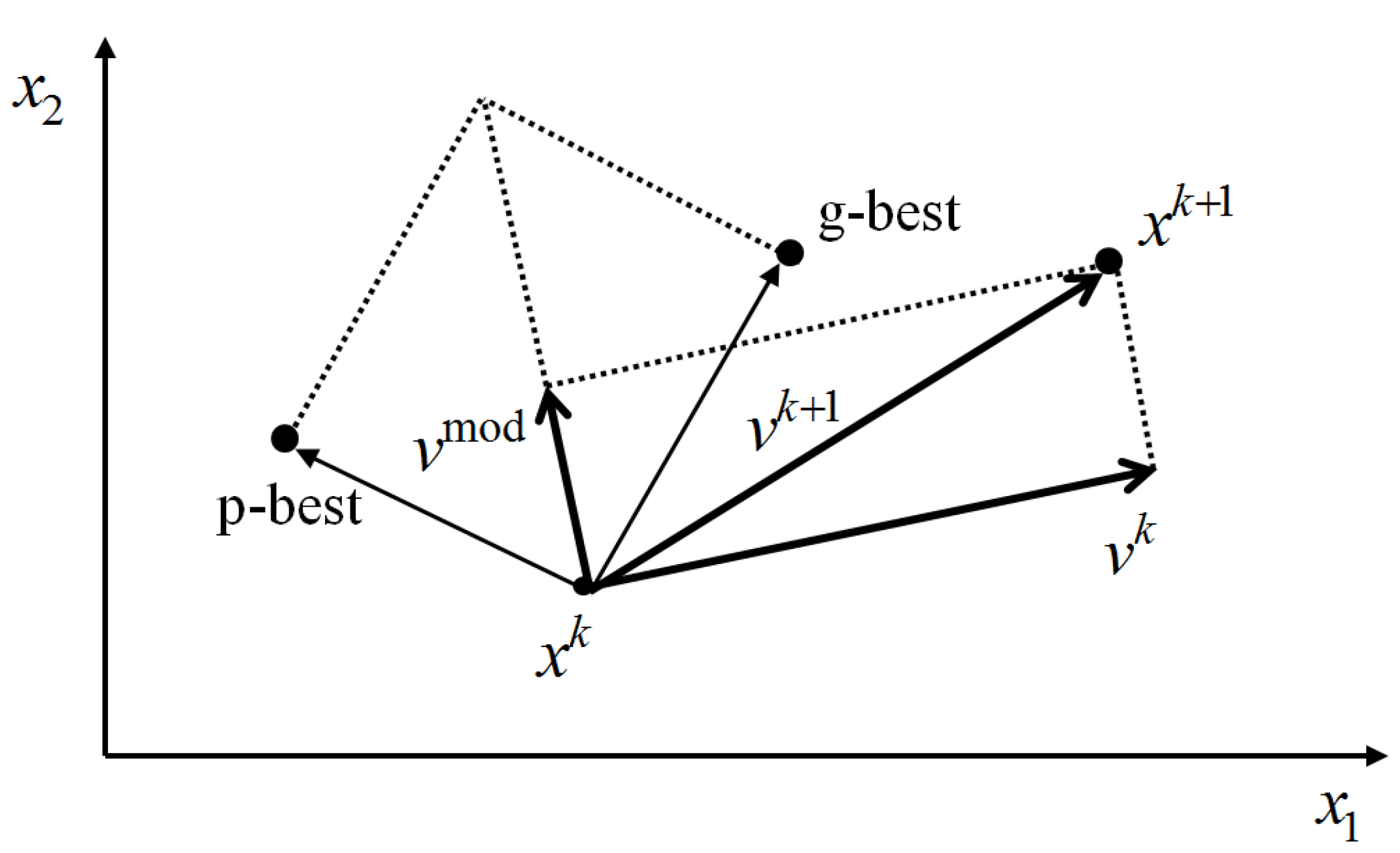
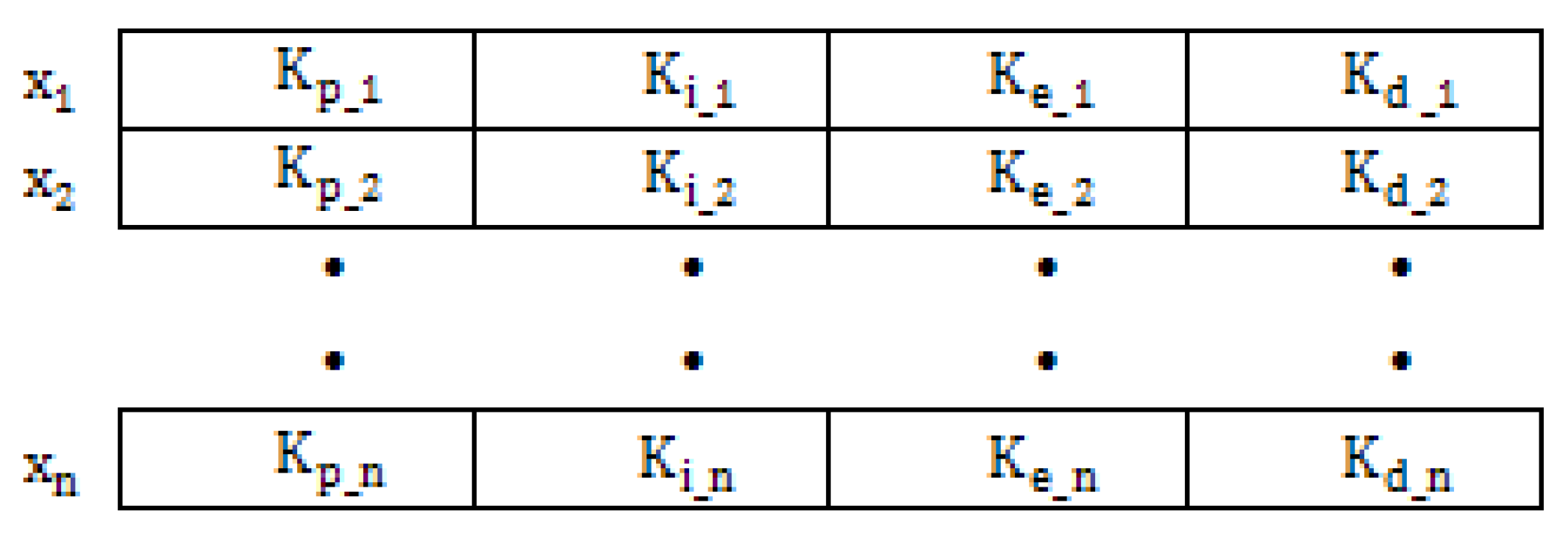
4.2. PSO Algorithm

4.3. Gain Tuning of Fuzzy PI Controller
5. Simulation Study
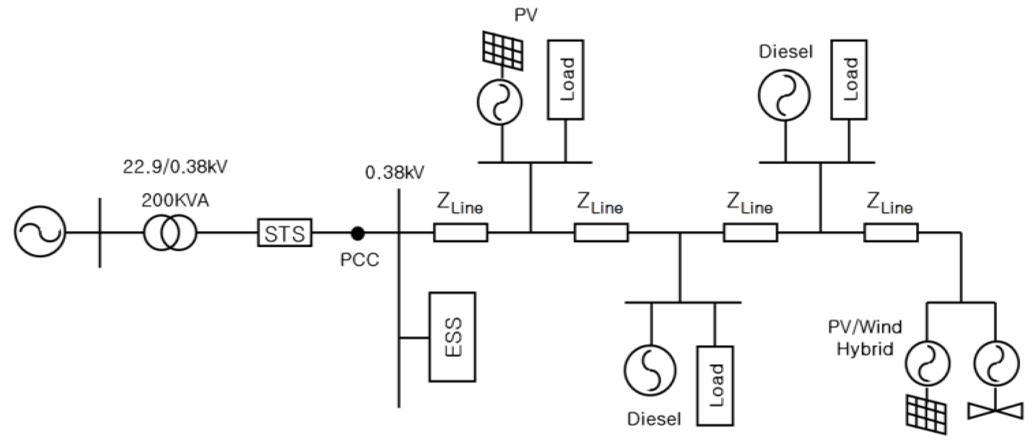
5.1. Configuration of a Test System

| Item | Description and Parameters |
|---|---|
| System Configuration |
|
| Generation Capacity |
|
| Load |
|
| Transformer | 3-phase 22.9/0.38 kV 200 kVA Leakage impedance %Z = 6% |
| Line Impedance | R = 0.1878 Ω/km, X = 0.0968 Ω/km |
5.2. Simulation Results
| Parameter | Value |
|---|---|
| Max Iteration | 50 |
| Population | 30 |
| C1 | 2.05 |
| C2 | 2.05 |
| ω | 0.9 ~ 0.4 |
Case A. Transition to Islanded Mode

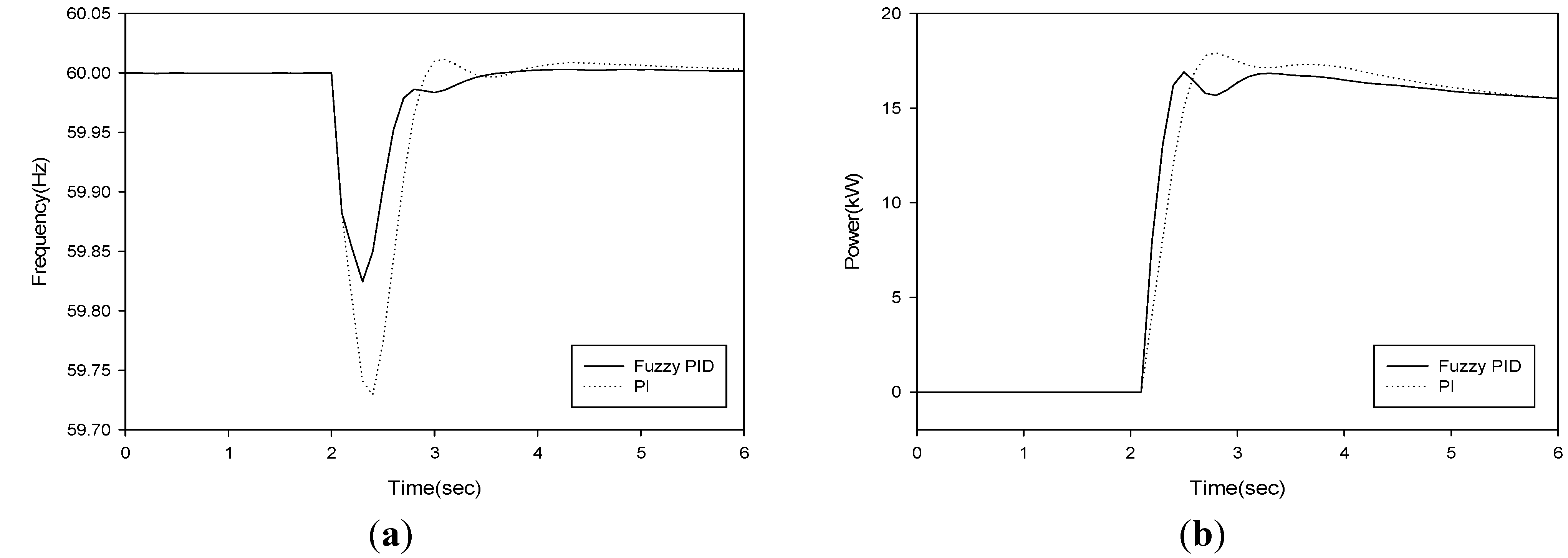
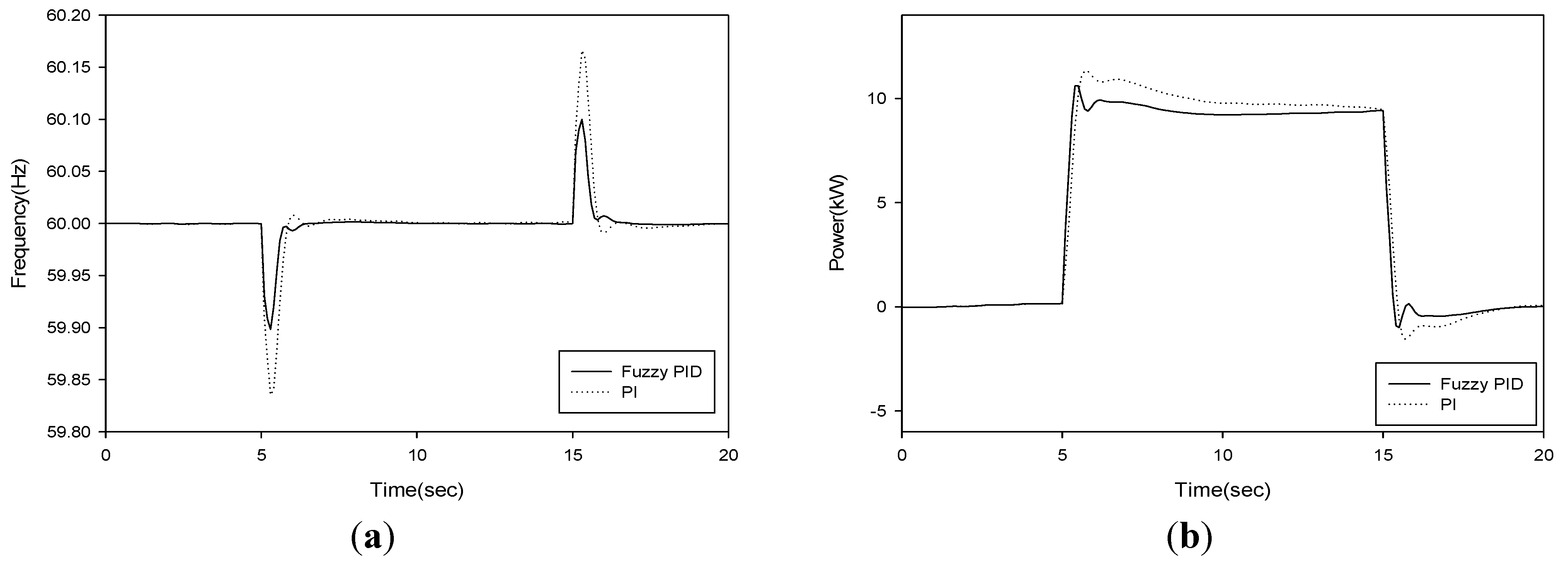
Case B. Islanded Operation with Step Load Change
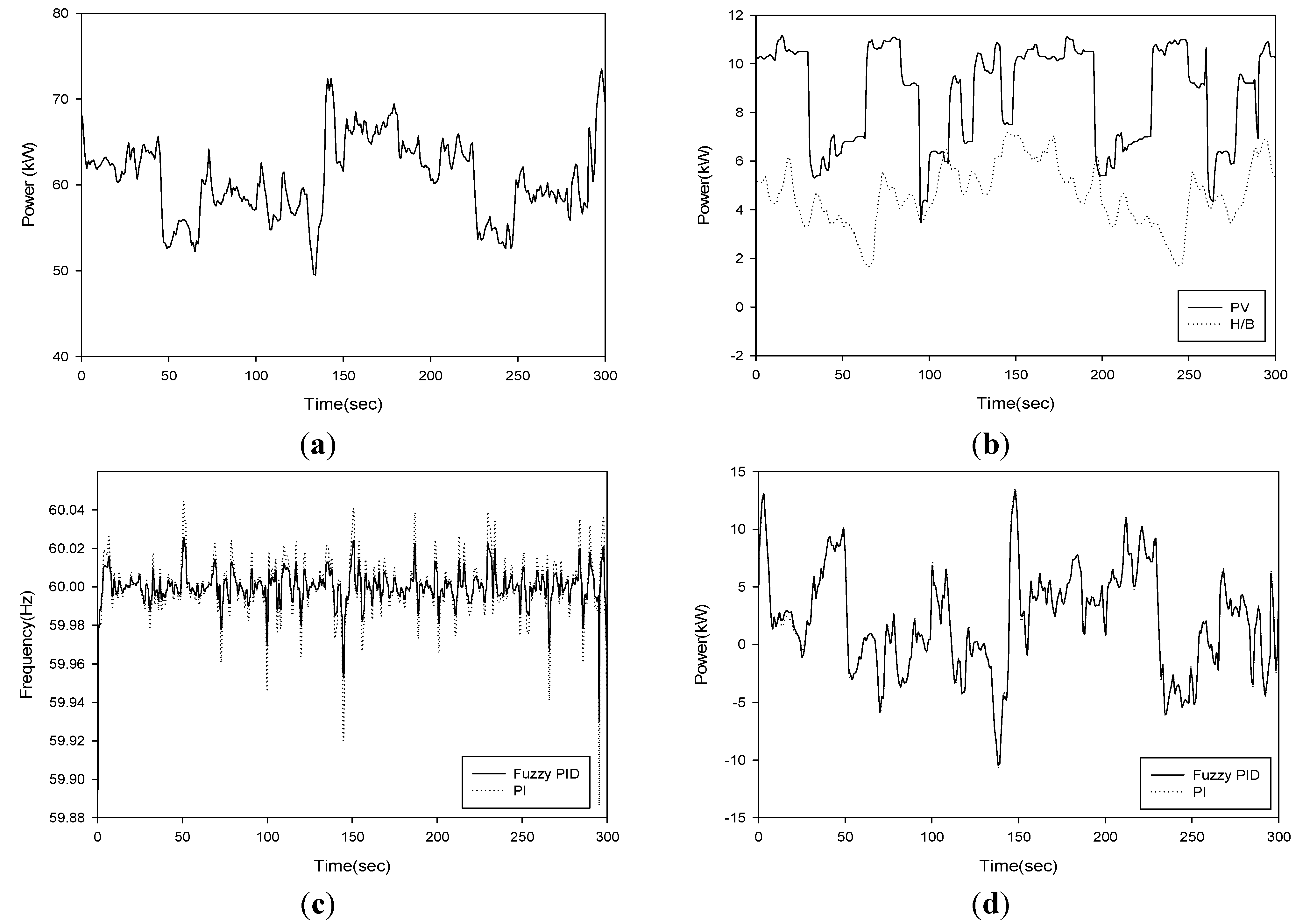
Case C. Islanded Operation with Varying Loads and RES Power Outputs

6. Conclusions
References
- Hatziargyriou, N.D.; Asano, H.; Iravani, H.R.; Marnay, C. Microgrids. IEEE Power Energy Mag. 2007, 4, 78–94. [Google Scholar] [CrossRef]
- Pogaku, N.; Prodanovic, M.; Green, T.C. Modeling, analysis and testing of autonomous operation of an inverter-based microgrid. IEEE Trans. Power Electron. 2007, 2, 613–625. [Google Scholar] [CrossRef]
- Carrasco, J.M.; Franquelo, L.G.; Bialasiewiez, J.T.; Galvan, E.; Guisado, R.C.P.; Prats, M.A.M.; Leon, J.I.; Moreno-Alfonso, N. Power-electronic systems for the grid integration of renewable energy sources: A survey. IEEE Trans. Power Electron. 2006, 4, 1002–1016. [Google Scholar]
- Lasseter, R.; Akhil, A.; Marny, C.; Stevens, J.; Dagle, J.; Guttromson, R. Integration of Distributed Energy Resources: The CERTS Microgrid Concept; LBNL: Berkeley, CA, USA, 2003. [Google Scholar]
- Venkataramanan, G.; Marnay, C. A Larger role for microgrids. IEEE Power Energy Mag. 2008, 3, 78–82. [Google Scholar] [CrossRef]
- Xiarnay, C.; Asano, H.; Papathanassiou, S.; Strbac, G. Policymaking for microgrids. IEEE Power Energy Mag. 2008, 6, 66–77. [Google Scholar]
- Kim, H.-M.; Kinoshita, T.; Lim, Y. Talmudic Approach to load-shedding of islanded microgrid operation based on multiagent system. J. Electr. Eng. Technol. 2011, 2, 284–292. [Google Scholar] [CrossRef]
- Kim, H.-M.; Kinoshita, T.; Shin, M.-C. A multiagent system for autonomous operation of islanded microgrid based on a power market environment. Energies 2010, 3, 1972–1990. [Google Scholar] [CrossRef]
- Kim, H.-M.; Kinoshita, T. A multiagent system for microgrid operation in the grid-interconnected mode. J. Electr. Eng. Technol. 2010, 2, 246–254. [Google Scholar] [CrossRef]
- Kim, H.-M.; Wei, W.; Kinoshita, T. A new modified CNP for autonomous microgrid operation based on multiagent system. J. Electr. Eng. Technol. 2011, 1, 139–146. [Google Scholar] [CrossRef]
- Amorim, A.; Cardoso, A.L.; Oyarzabal, J.; Melo, N. Analysis of the Connection of a Microturbine to a Low Voltage Grid. In Proceedings of the International Conference on Future Power Systems, Amsterdam, The Netherlands, 16–18 November 2005.
- Saha, A.K.; Chowdhury, S.; Chowdhury, S.P.; Crossley, P.A. Modeling and performance analysis of a microturbine as a distributed energy resource. IEEE Trans. Energy Convers. 2009, 2, 529–538. [Google Scholar] [CrossRef]
- Hatziargyriou, N. Microgrids—Large scale integration of micro-generation to low voltage grids. EU Microgrid Project; No. ENK-5-CT-2002-00610. National Technical University of Athens: Athens, Greece, 2004. [Google Scholar]
- Zbiniew, L.; Janusz, W.B. Supervisory control of a wind farm. IEEE Trans. Power Syst. 2007, 3, 985–994. [Google Scholar]
- Abbey, C.; Joos, G. Supercapacitor energy storage for wind energy applications. IEEE Trans. Ind. Appl. 2007, 3, 769–776. [Google Scholar] [CrossRef]
- Tripathy, S.C.; Kalantar, M.; Balasubramanian, R. Dynamic and stability of wind and diesel turbine generators with superconducting magnetic energy storage unit on an isolated power system. IEEE Trans. Energy Convers. 1991, 4, 579–585. [Google Scholar] [CrossRef]
- Thounthong, P.; Rael, S.; Davat, B. Analysis of supercapacitor as second source based on fuel cell power generation. IEEE Trans. Energy Convers. 2009, 1, 247–255. [Google Scholar] [CrossRef]
- Yunwei, L.; Vilathgamuwa, D.M.; Poh, C.L. Design, analysis, and real-time testing of a controller for multibus microgrid system. IEEE Trans. Power Electron. 2004, 5, 1195–1204. [Google Scholar]
- Li, Y.W.; Kao, C.N. An accurate power control strategy for power-electronics-interfaced distributed generation units operating in a low-voltage multibus microgrid. IEEE Trans. Power Electron. 2009, 12, 2977–2988. [Google Scholar]
- Tanabe, T.; Suzuki, S.; Ueda, Y.; Ito, T.; Numata, S.; Shimoda, E.; Funabashi, T.; Yokoyama, R. Control performance verification of power system stabilizer with an EDLC in islanded microgrid. IEEJ Trans. Power Energy 2009, 1, 139–147. [Google Scholar] [CrossRef]
- Kim, J.Y.; Jeon, J.H.; Kim, S.K.; Cho, C.H.; Park, J.H.; Kim, H.M.; Nam, K.Y. Cooperative control strategy of energy storage system and microsources for stabilizing the microgrid during islanded operation. IEEE Trans. Power Electron. 2010, 12, 3037–3048. [Google Scholar]
- Timbus, A.; Liserre, M.; Teodorescu, R.; Rodriguez, P.; Blaabjerg, F. Evaluation of current controllers for distributed power generation systems. IEEE Trans. Power Electron. 2009, 3, 654–664. [Google Scholar] [CrossRef]
- Yesil, E.; Guzelkaya, M.; Eksin, I. Fuzzy PID controllers: An overview. In Proceedings of the Third Triennial ETAI International Conference on Applied Automatic Systems, Skopje, Macedonia, 2003; pp. 105–112.
- Silva, C.W. Intelligent Control: Fuzzy Logic Applications; CRC Press: New York, NY, USA, 1995. [Google Scholar]
- Akbiyik, B.; Eksin, I.; Guzelkaya, M.; Yesil, E. Evaluation of the performance of various fuzzy PID controller structures on benchmark systems. In Proceedings of the 4th International Conference on Electrical and Electronics Engineering (ELECO’2005), Bursa, Turkey, 2005; pp. 388–393.
- Mann, G.K.I.; Hu, B.G.; Gosine, R.G. Analysis of direct action fuzzy PID controllers structures. IEEE Trans. Syst. Man Cybern. 1999, 3, 371–388. [Google Scholar] [CrossRef]
- Akagi, H.; Watanabe, E.H.; Aredes, M. Instantaneous Power Theory and Applications to Power Conditioning; IEEE Press: Piscataway, NJ, USA, 2007. [Google Scholar]
- Blaabjerg, F.; Teodorescu, R.; Liserre, M.; Timbus, A.V. Overview of control and grid synchronization for distributed power generation systems. IEEE Trans. Ind. Electron. 2006, 5, 1398–1411. [Google Scholar] [CrossRef]
- Timbus, A.; Liserre, M.; Teodorescu, R.; Rodriguez, P.; Blaabjerg, F. Evaluation of current controllers for distributed power generation systems. IEEE Trans. Power Electron. 2009, 3, 654–664. [Google Scholar] [CrossRef]
- Wu, Z.Q.; Mizumoto, M. PID type fuzzy controller and parameter adaptive method. Fuzzy Sets Syst. 1996, 1, 23–36. [Google Scholar]
- Kennedy, J.; Eberhart, R.C. Particle Swarm Optimization. In Proceedings of the IEEE International Conference on Neural Networks, Perth, Australia, 27 November–1 December 1995; pp. 1942–1948.
- Clerc, M. The Swarm and the Queen: Towards a Deterministic and Adaptive Particle Swarm Optimization. In Proceedings of the Congress of Evolutionary Computation, Washington, DC, USA, 6–9 July 1999; pp. 1951–1957.
- Eberhart, R.C.; Shi, Y. Comparing Inertia Weights and Constriction Factors in Particle Swarm Optimization. In Proceedings of the IEEE Conference on Evolutionary Computation, San Diego, CA, USA, 16–19 July 2000; pp. 84–88.
- Kim, J.-Y.; Kim, S.-K.; Park, J.-H. Contribution of an energy storage system for stabilizing a microgrid during islanded operation. J. Electr. Eng. Technol. 2009, 4, 194–200. [Google Scholar] [CrossRef]
© 2011 by the authors; licensee MDPI, Basel, Switzerland. This article is an open access article distributed under the terms and conditions of the Creative Commons Attribution license (http://creativecommons.org/licenses/by/3.0/).
Share and Cite
Kim, J.-Y.; Kim, H.-M.; Kim, S.-K.; Jeon, J.-H.; Choi, H.-K. Designing an Energy Storage System Fuzzy PID Controller for Microgrid Islanded Operation. Energies 2011, 4, 1443-1460. https://doi.org/10.3390/en4091443
Kim J-Y, Kim H-M, Kim S-K, Jeon J-H, Choi H-K. Designing an Energy Storage System Fuzzy PID Controller for Microgrid Islanded Operation. Energies. 2011; 4(9):1443-1460. https://doi.org/10.3390/en4091443
Chicago/Turabian StyleKim, Jong-Yul, Hak-Man Kim, Seul-Ki Kim, Jin-Hong Jeon, and Heung-Kwan Choi. 2011. "Designing an Energy Storage System Fuzzy PID Controller for Microgrid Islanded Operation" Energies 4, no. 9: 1443-1460. https://doi.org/10.3390/en4091443