1. Introduction
Since photovoltaic (PV) installed power increases all over the world, solar technology is now strongly present in the electricity market, and it cannot be seen only as a vision of the future. As solar energy is one of the most abundant free sources in nature, the generation of electrical energy, compared with other counterparts, is effectively convenient, in particular in countries of the Mediterranean area, for the greater part of the year [
1,
2]. PV generation systems are actually available in different power sizes covering the range from domestic applications to large power generation plants.
Many different improvements have been proposed and experimented to enhance efficiency not only in energy conversion (PV fields) but also in energy management (power converters). In recent times, multi-level inverters such as H bridge multi-cell cascaded inverter [
3], Neutral Point Clamped (NPC) [
4] and Active Point Clamped (APC) [
5] have also been used for a more efficient and effective PV power conversion [
6].
Many inverter topologies have been patented, within the market development, to solve some common problems of the PV plants such as leakage currents due to parasitic capacitance of the panel and efficiency losses due to the transfer of reactive energy between the grid filters and the DC bus capacitor [
7,
8,
9]. Moreover, some particular topologies have been conceived of for the fault tolerant operation of PV plant [
10,
11,
12,
13,
14,
15,
16]. Many of the novel patented circuits can operate without boost choppers and high frequency transformers, while on the other hand ancillary functions require more flexibility in the control design [
6,
17]. As foreseen in recent investigations, all the emerging technologies have been recently employed to optimize the electricity production from solar energy. In particular, MPPT control (Maximum Power Point Tracking) is one of the most interesting aspects of renewables. In general, a boost chopper is used to follow the maximum power point, while inverters are used only to adjust voltages and currents to meet the load/grid requirements [
18,
19,
20,
21]. Therefore, a boost chopper is very often integrated in the most utilized all-in-one commercial PV power converters. The use of boost choppers, however, contributes to reduce the reliability, the efficiency and the economical convenience, due to the presence of cascaded converters and the higher complexity of the control system [
22].
In more recent times, the possibility of realizing the MPPT control in grid-connected systems without AC voltage boosts, directly with transformers or passive filters, has been studied and discussed [
23]. This paper presents an analytical and numerical investigation on a medium scale PV power generator connected to an active network with its power flow and MPPT control system. The analysis here shows that the inverter presents two degrees of freedom. In particular, these two degrees of freedom consist in two control variables, the direct and the quadrature line axis current components, which can be profitably utilized to control the active power, the reactive power and the MPPT at the same time.
2. The Plant under Analysis and Its Modeling
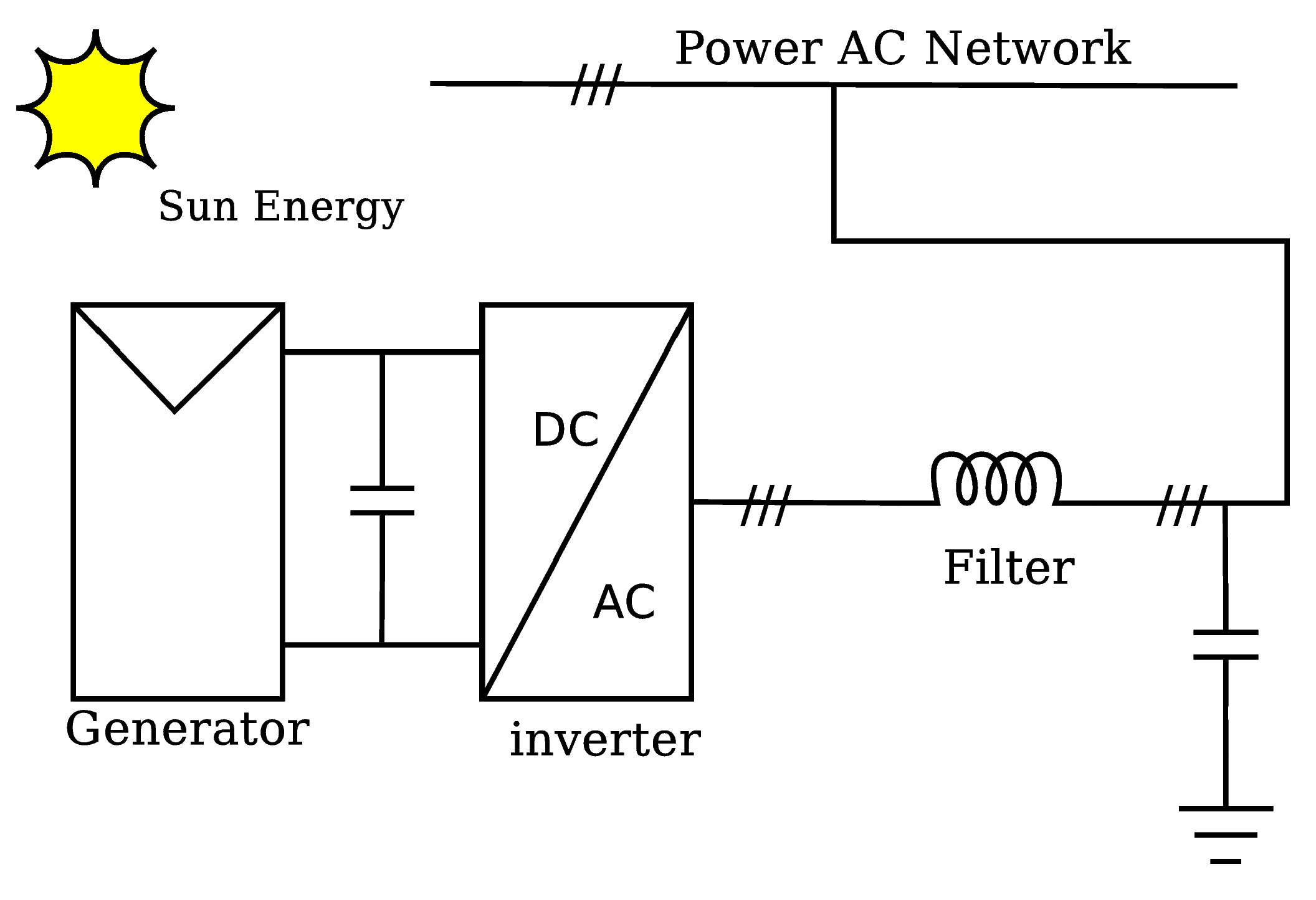
The plant under investigation consists of a PV generator directly coupled with a Voltage Source Inverter (VSI) as said in the introduction. A simplified scheme of the system is shown in
Figure 1. The inverter is connected to the network or to the load through an intermediate LC filter to meet power quality grid requirements. If an output transformer is required, the filter can be made of the short circuit transformer impedance and by a capacity bank.
The authors here recall the model equations of each component used to build the model of the whole system.
Figure 1.
Scheme of the plant under investigation.
Figure 1.
Scheme of the plant under investigation.
For the PV Generator, in the most cases, the Hussain model is considered [
24] [see Equation (
1)].
where:
i is the output current;
iPV is the sun generated current;
I0rev is the PN junction reverse current;
q is the electron charge;
vPV is the output voltage;
RS is the internal cell resistance;
n is a quality factor depending on the cell type;
K is the Boltzmann constant;
T is the absolute temperature.
For the three-phase inverter and the grid, the model is written directly in
DQ0 reference frame to achieve a completely DC model. The fixed three-phase to rotating reference frame transformation is represented by the matrix:
with
θ =
ωt = 2
πft where
f is the grid frequency and
t is the time. In the
DQ0 rotating reference frame the inverter equations are given by:
where:
C is the DC Link capacitance.
uDC is the DC-link voltage;
i0 is the input inverter current;
SD and SQ are the direct and quadrature components of the inverter switching functions;
iD and iQ are the direct and quadrature components of inverter output current;
vD and vQ are the direct and quadrature components of inverter output voltage.
The inverter input current is, instead, given by the equation:
where
R0 and
L0 are, respectively, the resistance and the inductance of the wiring between the PV generator and the inverter.
For the active power grid the model equations are:
In this case, R and L are the resistance and the inductance of the grid till to a prevalent power node, and eD and eQ are the direct and quadrature components of the grid voltage in the prevalent power node.
It is usual, for systems including power converters, to consider the averaged model.
Averaging the model implies to consider the “instantaneous” mean value of each quantity
xav(
t) defined by:
in which
TPWM is the converter switching period.
By considering now the steady state and remembering that in the average model the switching functions
Sk are to be replaced with duty cycles
Fk [
20,
21], the system model becomes (with
av subscript omitted):
Capital letters are just used here to point out steady state. Equation (
7) comes from Equations (3–5), rewritten by vanishing all the derivatives because after the DQ transformation the system is a DC one. The nonlinear Equation (
7) clearly has no closed form solution. Solving the two last equations of the system (7) with respect to the current components, one finds:
Substituting Equation (
8) into the fourth equation of the system [Equation (
7)], the explicit expression of
I0 is obtained:
If the DQ reference frame is chosen with the D axis coinciding with the vector of the grid voltage, the previous expression simplifies to:
where
ED =
Ugrid and
EQ = 0. After some algebraic manipulations, one has:
where
X =
ωL, and
. It is obvious that if the PV generator gives constant power, then
UDC and
I0 are fixed. Therefore, in Equation (
11)
FD and
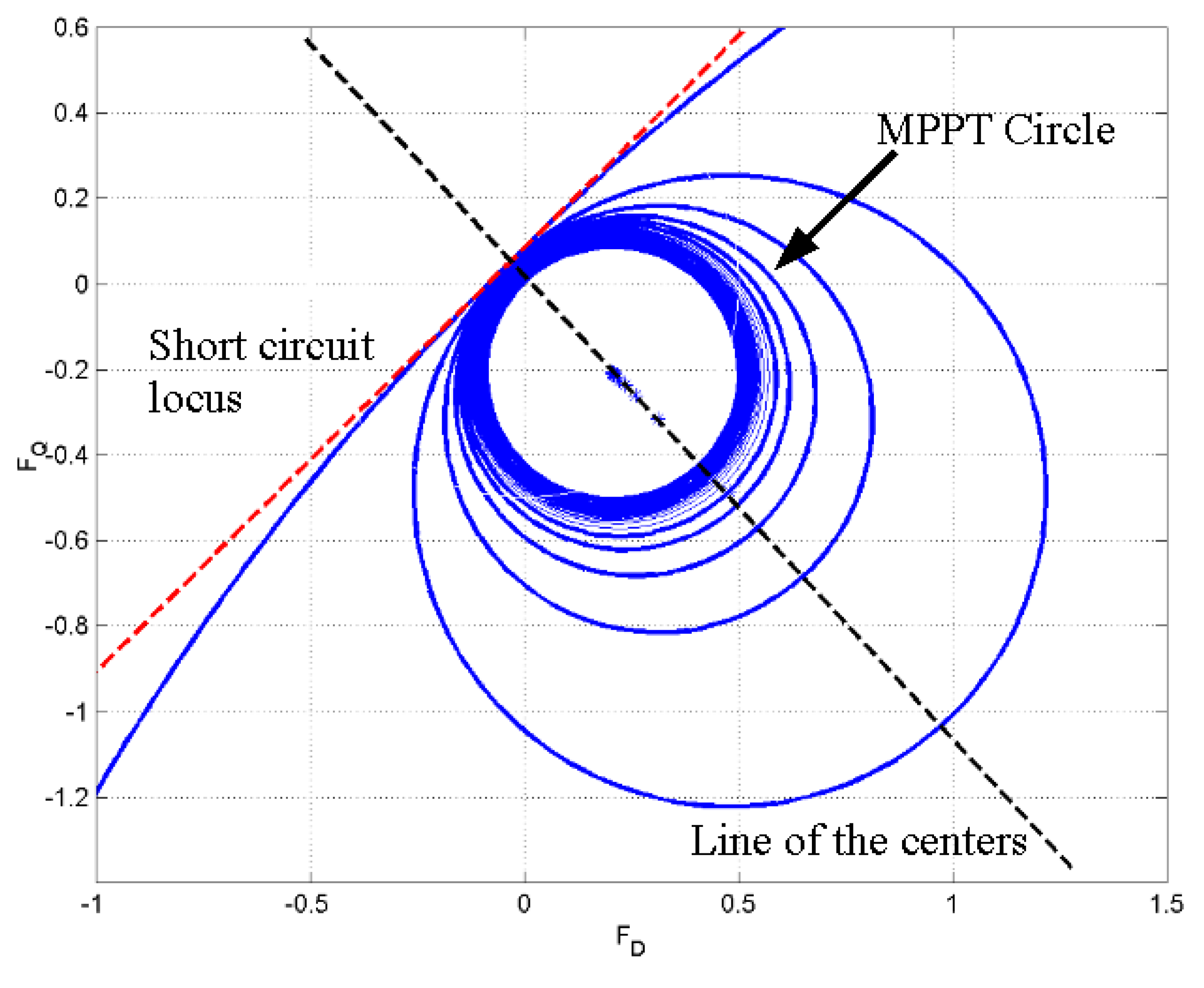
FQ assume the values for which the inverter transfers a given power generated by the PV panel. Equation (
11) represents, therefore, the “constant power circles” in the
FD–
FQ plane. A plot of these circles is given in
Figure 2.
The coordinates of the circle centers are:
and the circle radii are:
The centers lie on a line whose slope is −
X/
R. The singular locus corresponding to the short circuit condition (zero-power) of the PV generator is represented by Equation (
14).
Figure 2.
Constant Power Circles on the FD − −FQ plane.
Figure 2.
Constant Power Circles on the FD − −FQ plane.
The constant power circles are very close to each other in the quasi-constant voltage region of the PV voltage-current characteristic, while they are more sparse in the quasi-constant current region. Between these two regions, the Maximum Power circle is located. The transmission of a particular value of active power to the AC network may be realized with different FD–FQ values (theoretically all the FD–FQ pairs of a constant power circle). This corresponds to different values of inverter voltage and current, i.e., different values of the reactive power, with active power constrained by the PV generator. In general, the inverter may be controlled with two degrees of freedom, which are the ID and the IQ components. These components can be fully exploited only if the D–Q channels are decoupled.
In order to determine the
ID and
IQ expressions, the active power balancing Equation (
15) and the expression of the reactive power [Equation (
16)] are considered.
where
UDCI0 is the generated power,
represents the chopper losses, and
UgridID is the active power delivered to the grid.
The solution of Equations (15) and (16) leads to the following values of the current components:
The knowledge of ID and IQ allows the full determination of the output inverter voltage vector. The intersection of this vector with the proper constant power circle allows, finally, the determination of FD and FQ for the inverter control.
The presented mathematical model cannot be immediately and effectively exploited for the control of the three-phase inverter without carrying out an accurate system identification parameters. Nevertheless, to overcome this drawback, the results of the conducted analysis suggest the structure of the closed loop control system, which will be discussed in the next section.
3. The System for Power Flow Control
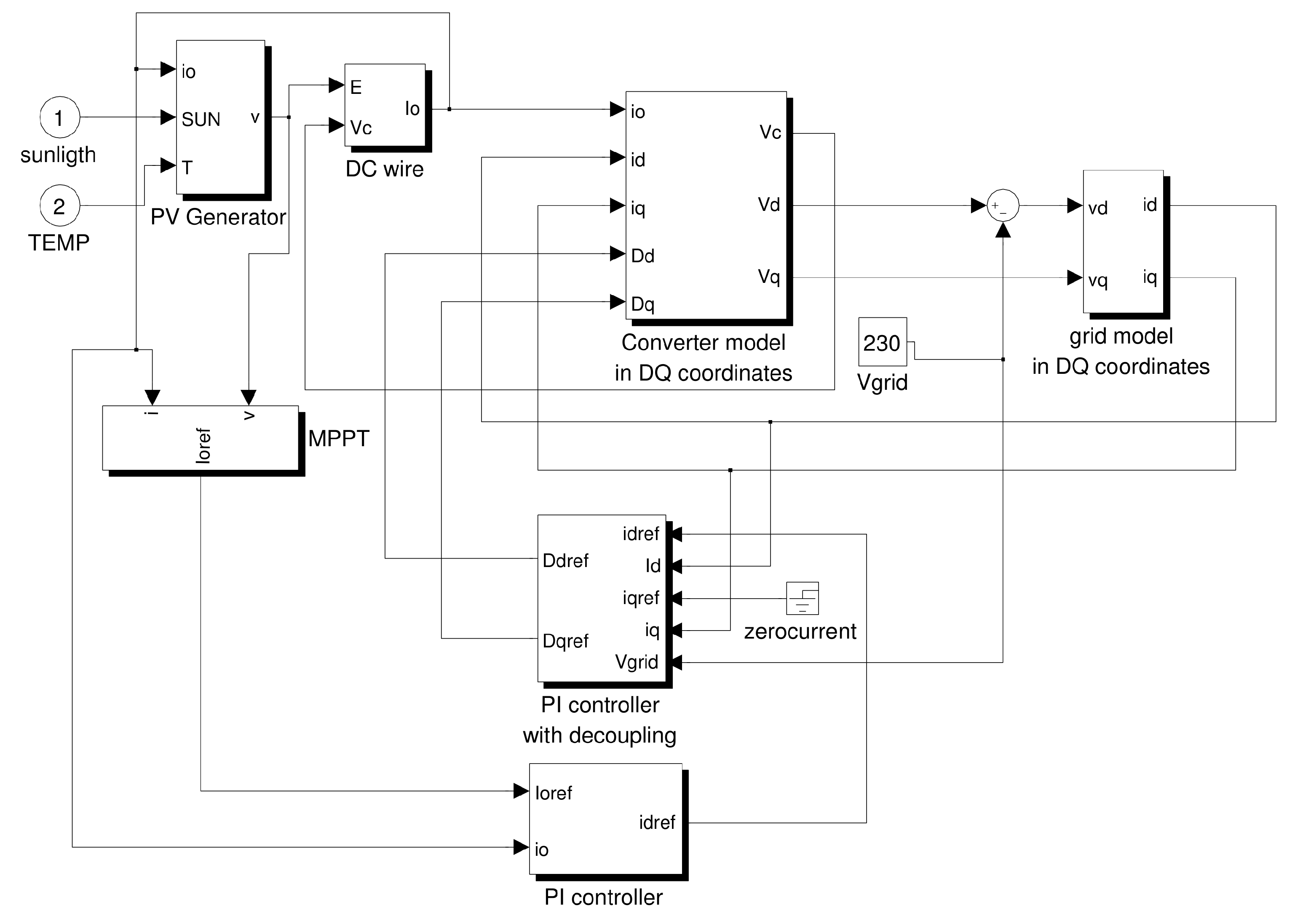
The chosen control system has the structure plotted in the block scheme of
Figure 3.
Figure 3.
Block scheme of the control system.
Figure 3.
Block scheme of the control system.
The system has two nested control loops. The innermost loop uses two decoupled current regulators for the D and the Q channels. The outermost loop uses, instead, a single regulator generating the ID current reference coming from the MPPT system output.
The DQ inverter equations suggest that for MPPT purposes the current Io can be regulated by varying the DC link voltage with respect to that of the PV generator. The same equations suggest that the DC link voltage can be varied by controlling a current, namely ID or IQ. By synchronizing the reference frame so that its D axis overlaps the grid voltage vector, the ID regulation channel is used for the adjustment of UDC and i0, i.e., for active power regulation, while the IQ regulation channel is used to vary reactive power. When the IQ reference is set to zero, the control system provides the injection in the network of active power only. A non-zero IQ value may be chosen on the basis of reactive power grid demand. However, reactive power values cannot be very high because its transmission can cause large fluctuations in the DC Link voltage around its mean value and makes stability a critical issue for the system.
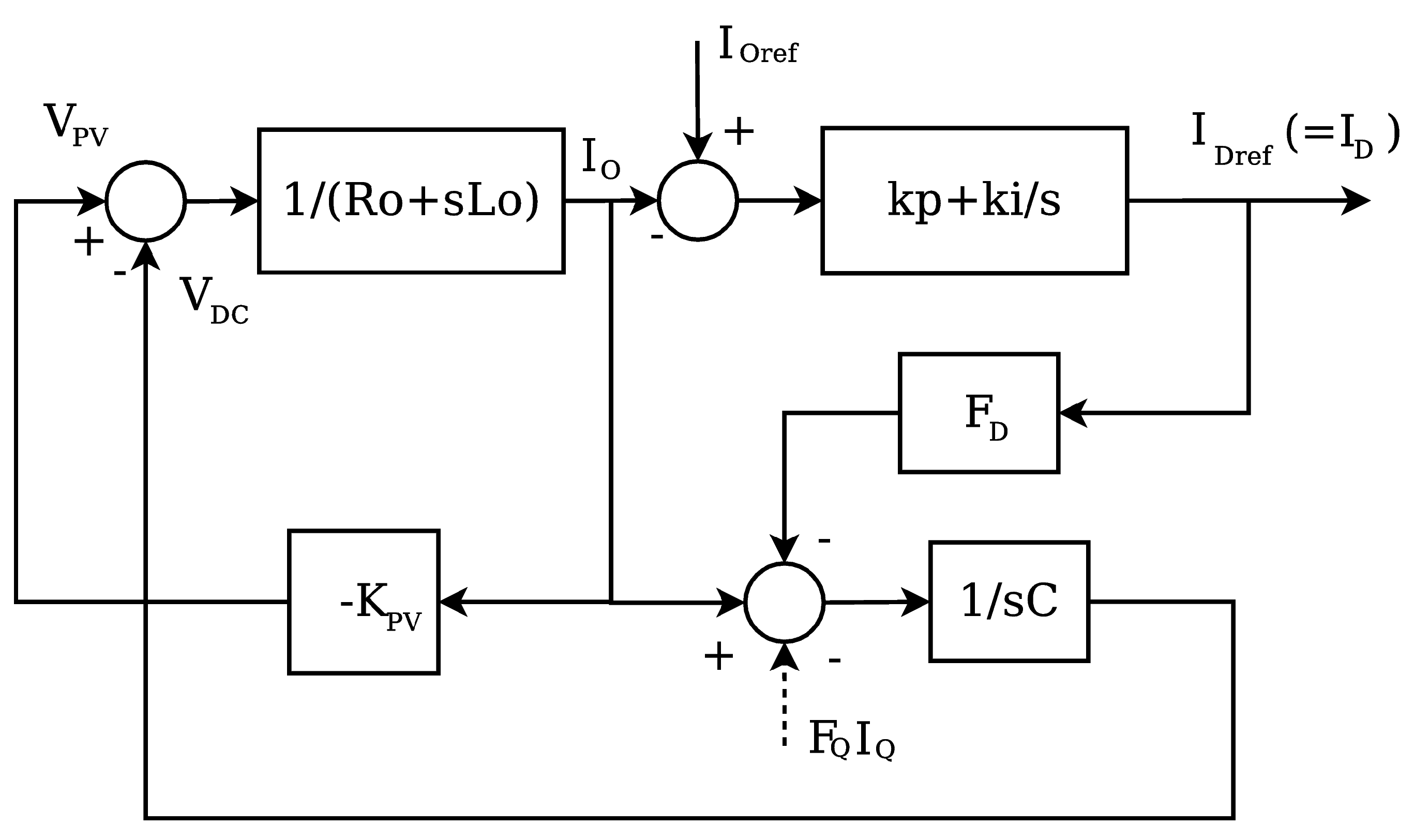
Stability analysis considers the transfer function for small signals binding the
i0 current reference to its actual value. A linearized version of the system may be reached by considering the inner control loop behavior as instantaneous and the voltage-current link of the PV panel as linear near the maximum power point (
VPV = −
KPV I0, where
KPV is the slope of the V–I generator characteristic at a steady state working point). A block scheme of the outer control loop is resumed in
Figure 4.
Figure 4.
Scheme of the linearized outer control loop of the plant.
Figure 4.
Scheme of the linearized outer control loop of the plant.
For the sake of simplicity, no action of the quadrature channel is considered because it does not change the system poles. After the linearization, by analyzing the scheme of
Figure 4, the following transfer function results:
where
kp and
ki are the regulator parameters.
By applying the Routh Criterion, the stability condition is found at:
Robust stability is guaranteed if the polynomial in Equation (
20) is positive and far away from zero considering all the
KPV values in a wide range near the maximum power point for the generator. Obviously, the stability condition, formed for the linearized system, provides only a first choice to be refined and must be verified experimentally on the real system for possible adjustments.
The MPPT algorithm provides, therefore, the value of Io corresponding to the maximum power transfer. The error signal is processed by the PI controller that provides the ID current set-point. The reference signal for IQ is null or independently generated depending on the grid demands.
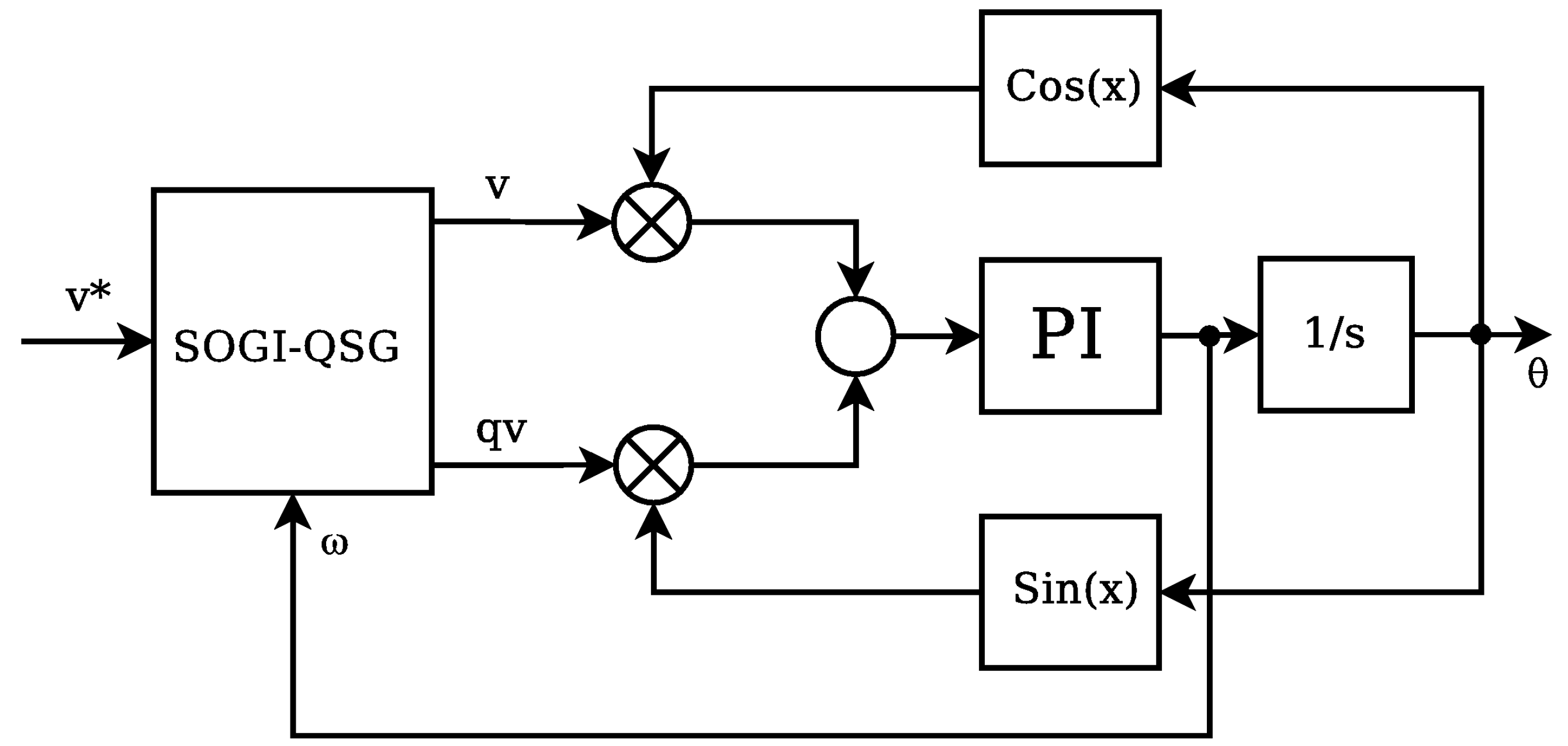
The control system requires the presence of a PLL (Phase Locked Loop) device both for synchronization and for giving effect to the decoupling of the D and Q control channels. This is usually a common issue for grid connected power PV systems.
Although the problem of the inverter-network synchronization is outside the aims of this article, it is interesting to recall that, recently, the solutions to this problem have gained considerable advances [
6,
25]. The SOGI (Second Order Generalized Integrator) has been used as a Quadrature Signal Generator (QSG-SOGI) in PLLs achieving smaller steady state disturbances [
26,
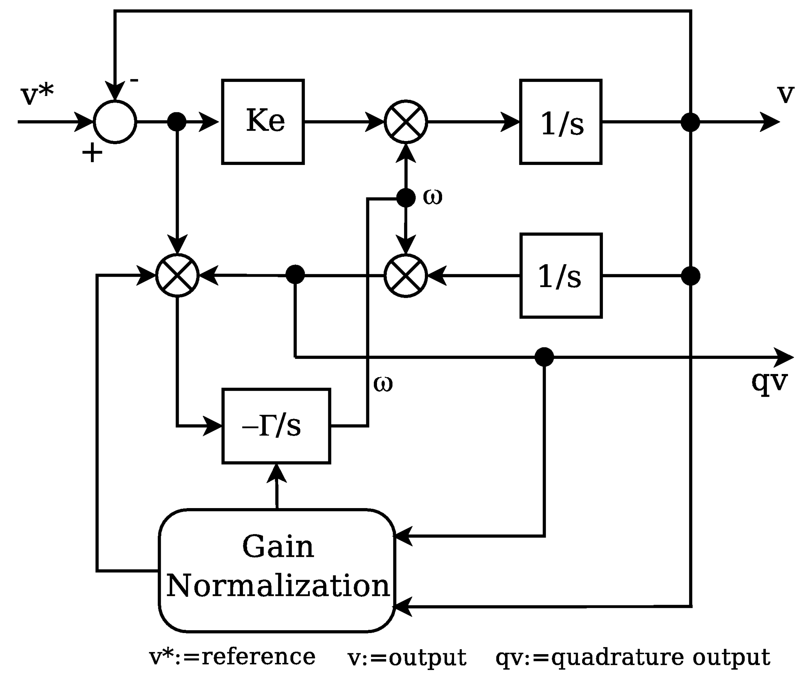
27]. On further investigations, the SOGI-FLL (Frequency Locked Loop SOGI) was realized. Its later upgrade with gain normalization has increased the stability margins of the frequency and phase follower. In both systems it is simple to set the specific time response even at adverse grid conditions (e.g., harmonic distortion, flickering, voltage sags,
etc.) [
28].
Figure 5.
Quadrature signal based PLL with a SOGI-QSG system (qv is a quadrature signal with respect to v).
Figure 5.
Quadrature signal based PLL with a SOGI-QSG system (qv is a quadrature signal with respect to v).
Figure 6.
Scheme of the SOGI-FLL system (The gain normalization block provides ).
Figure 6.
Scheme of the SOGI-FLL system (The gain normalization block provides ).
4. Simulations
Many different simulations were made to verify the validity of the control system. These simulations have been carried out with MATLAB Simulink software package, building the control scheme of
Figure 3 directly in the DQ coordinate reference frame, and using the inverter average model. By using the average model, the ripple of all variables is neglected, so simulation results appear to be smooth. Grid side voltages and currents are back transformed in the fixed three-phase reference frame to be plotted as sinusoidal signals.
Simulation results are shown in the per-unit systems. In particular, for PV DC-side quantities, the reference values are the no load voltage and the short circuit currents at standard conditions,
i.e.,
T = 25 °C and
S = 1 W/m
2 irradiation, air mass 1.5, no wind [
2]. For the AC-side quantities, the reference voltage is the peak value of the rated grid voltage and the reference current is that corresponding to the maximum active power peak at the standard condition specified above.
Various events have been considered in the simulations for the transient study. Among them, the following are considered to evaluate the control performance:
a low change in the weather conditions (e.g., sunspot, temperature, effect of a fast passing cloud) at cosϕ = 1 in the time range 3–6 s;
a step change in reactive power demand with all other stationary conditions at t = 7 s;
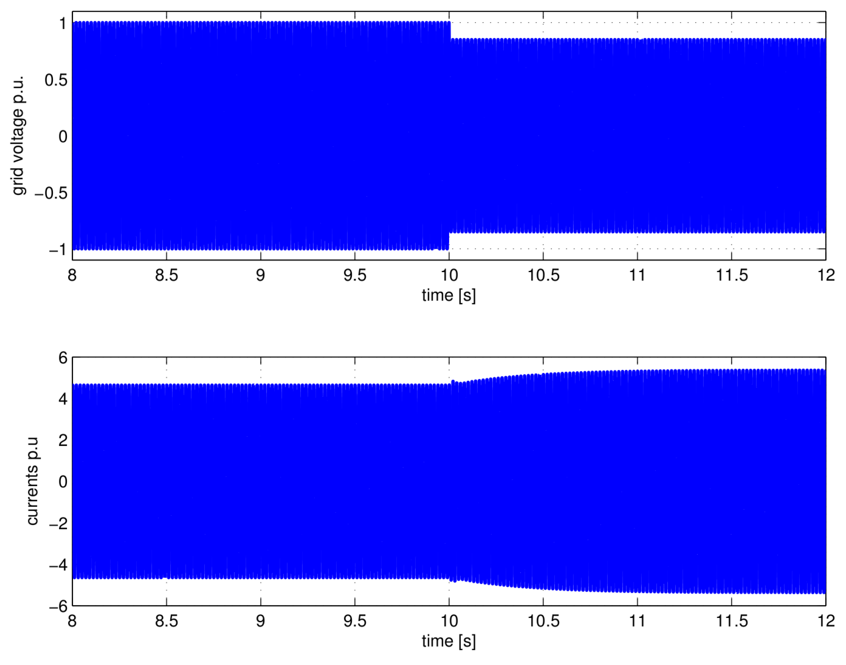
a grid voltage peak step change (under-voltage, 15%) at t = 10 s.
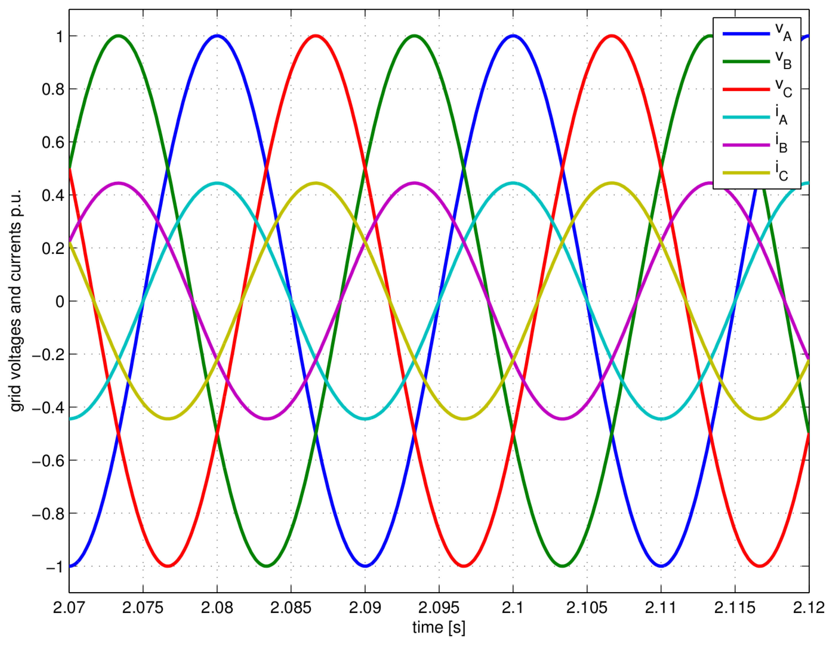
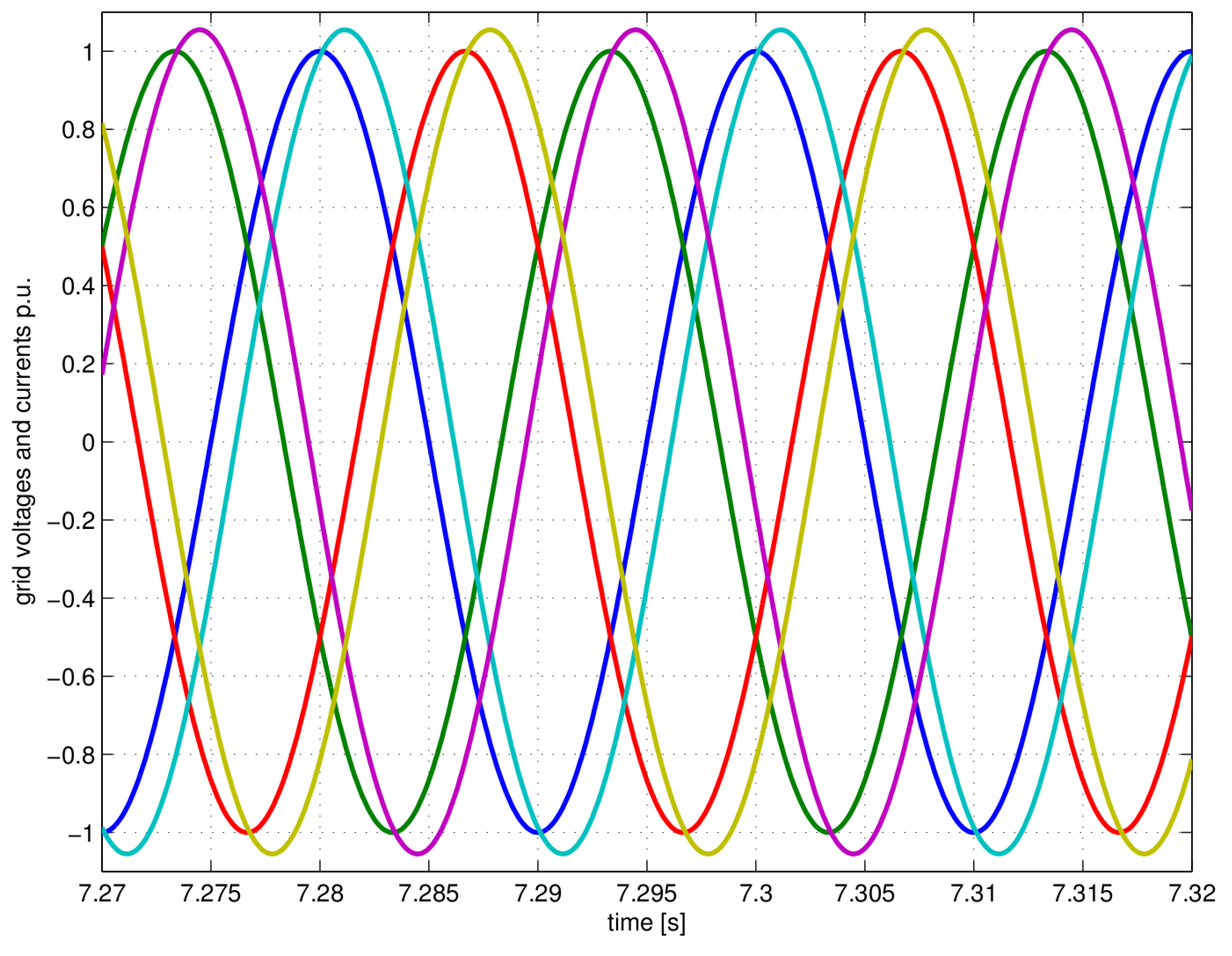
Figure 7 shows voltages and currents on the grid side at steady state with zero reactive power delivered before the weather perturbation occurs. In this condition, the control system manages the output voltages to hold the output currents in phase with the grid voltage. Null power factor is maintained also if a change in weather condition occurs.
Figure 8 shows, instead, the same voltages and currents at steady state with a non-zero reactive power demand.
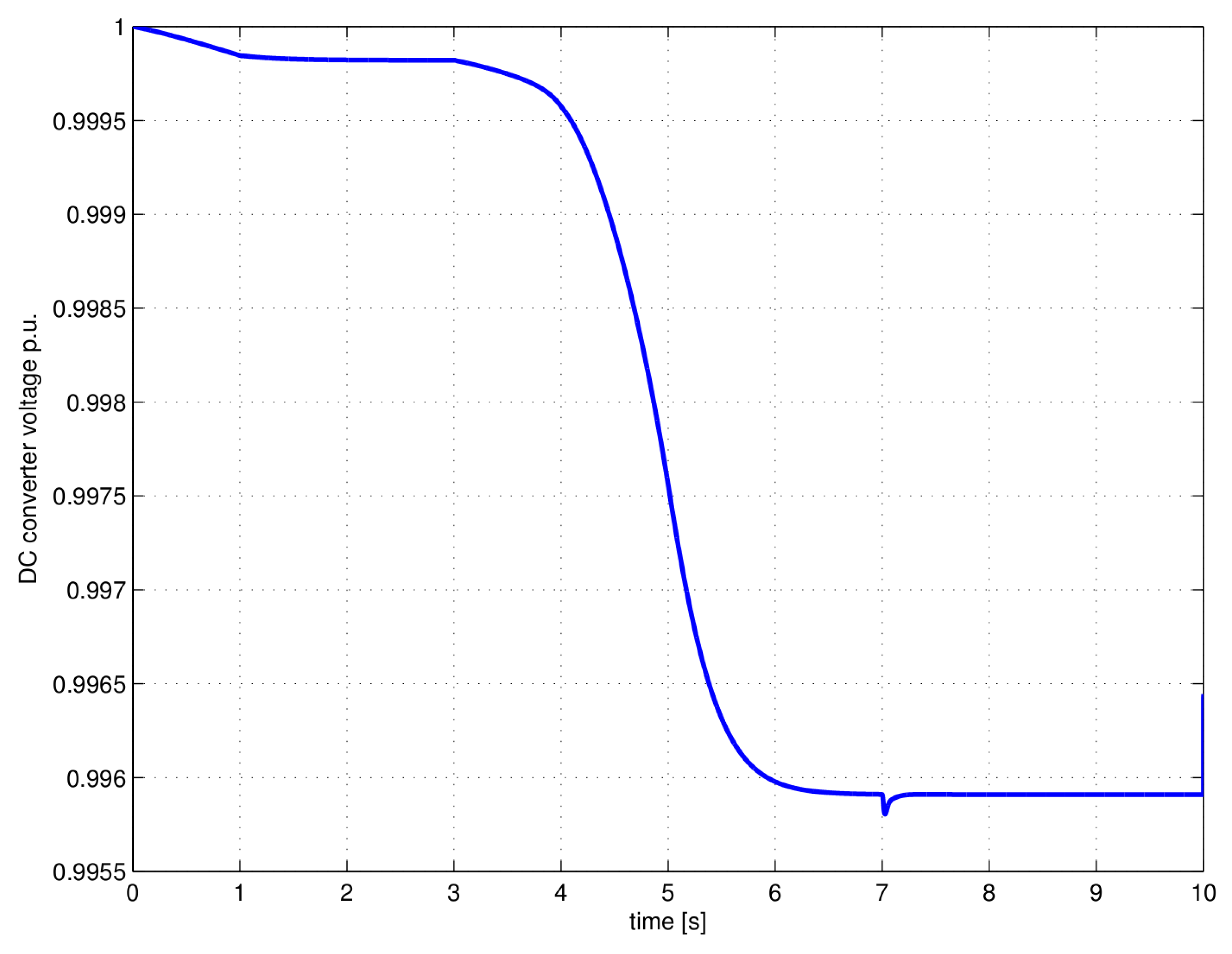
Figure 9 shows the variation of the DC Link voltage as a consequence of the control system operation to reach the peak power after a slow weather change developed in about 3 s. With evidence of
Figure 9, a very small voltage variation is required to adjust the current
I0 because of the small impedance of DC wires connecting the PV generator and the inverter.
Figure 9 shows also the effect on DC Link voltage of the step change in reactive power demand at
t = 7 s. The reactive power step has a poor influence on the DC Link voltage. However, after the small transient, the steady state value of
uDC does not change.
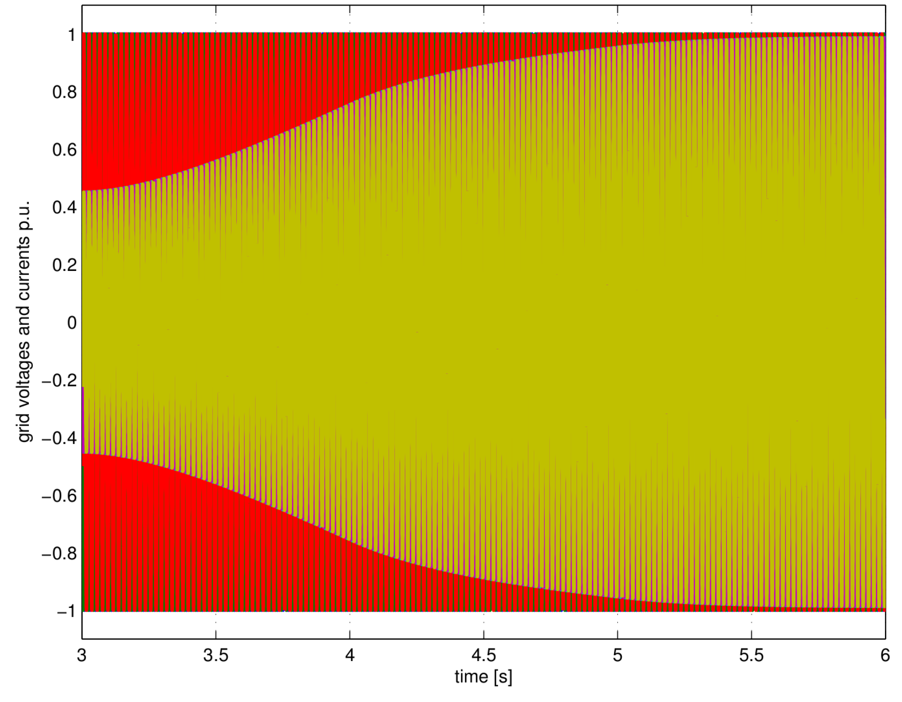
Figure 10 shows the transient of the output currents (with the grid voltages plotted in red) on the AC-side due to a change of the
I0 reference given by the MPPT algorithm. The variation of currents is slow like the change in the weather condition detected by the power peak tracker.
Figure 7.
Grid Voltages and Currents (in p.u. system) at steady state for zero reactive power delivered.
Figure 7.
Grid Voltages and Currents (in p.u. system) at steady state for zero reactive power delivered.
Figure 8.
Grid side voltage and currents (in p.u. system) at steady state for non-zero reactive power (color legend is the same as in
Figure 7).
Figure 8.
Grid side voltage and currents (in p.u. system) at steady state for non-zero reactive power (color legend is the same as in
Figure 7).
Figure 9.
Variation of the DC Link voltage during the intervention of the control system.
Figure 9.
Variation of the DC Link voltage during the intervention of the control system.
Figure 10.
Grid Voltages (red) and Currents (yellow) variation in p.u. due to a slow change of reference of the power peak tracker.
Figure 10.
Grid Voltages (red) and Currents (yellow) variation in p.u. due to a slow change of reference of the power peak tracker.
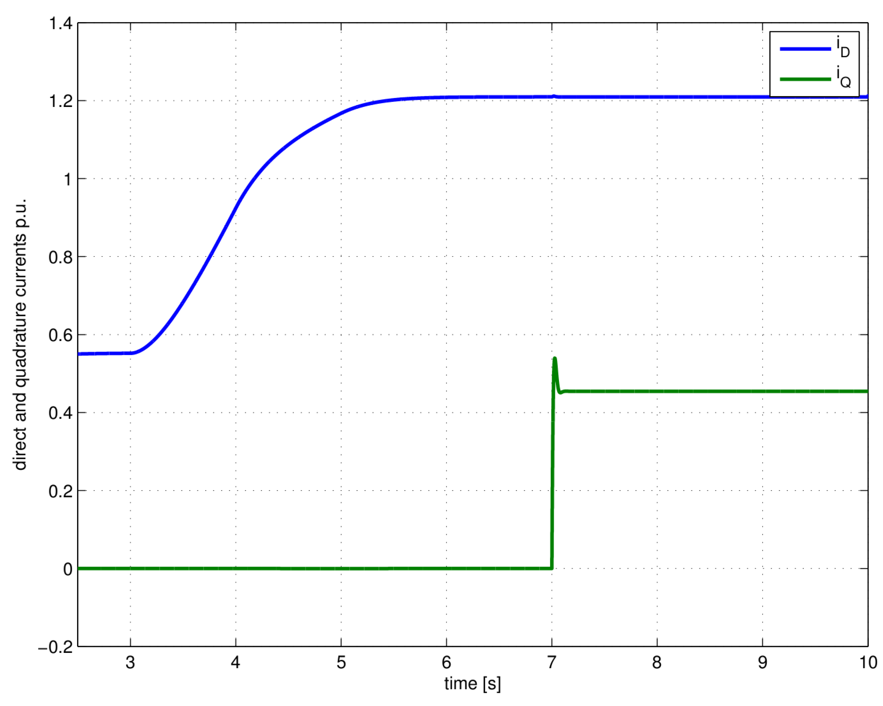
The same variation is shown in
Figure 11 (considering the time range 3–6 s) for the direct and the quadrature current components.
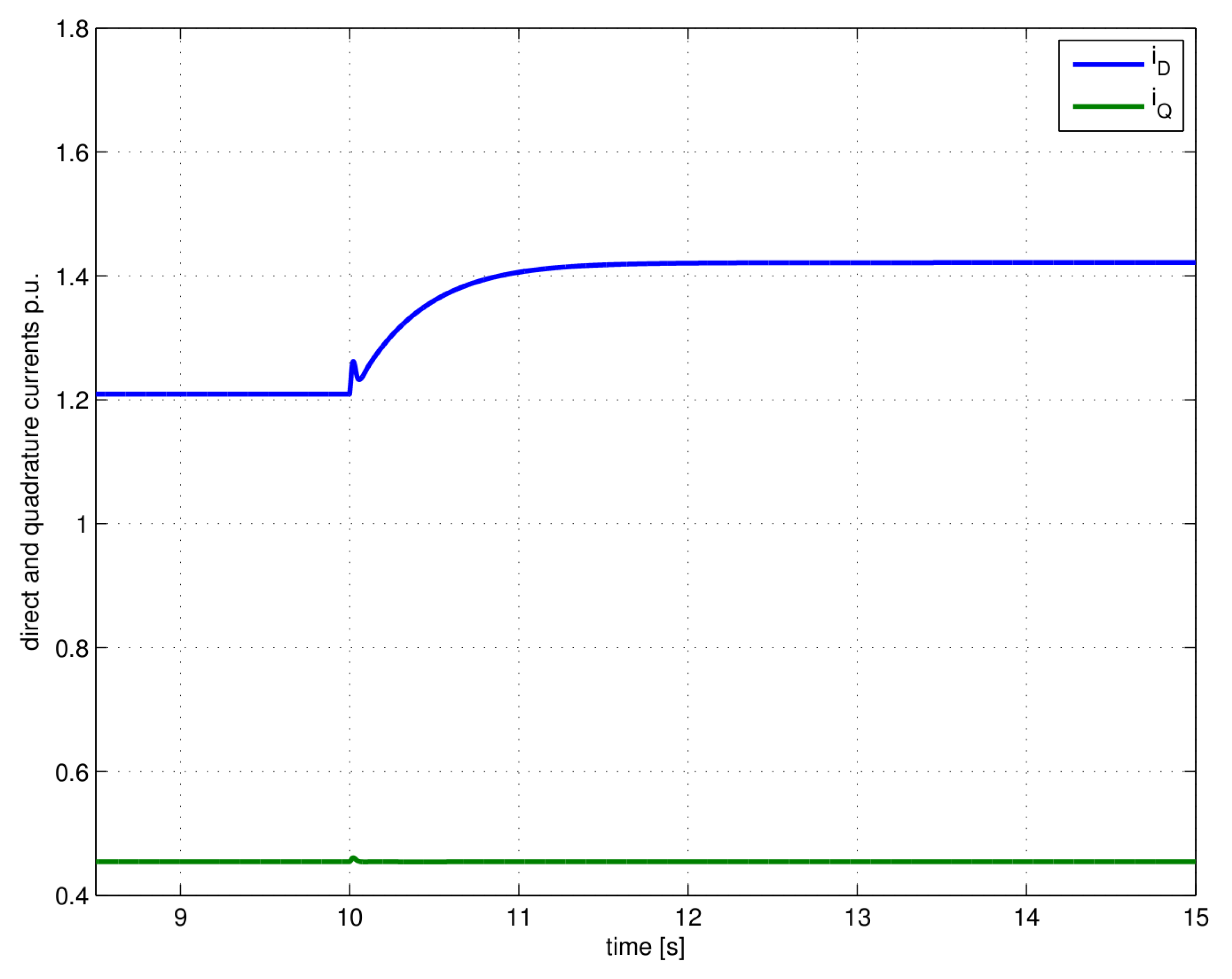
The power peak tracker modifies the Io reference. These values reflect on the iD reference, so the currents on the DC and AC sides are adjusted acting on the inverter duty cycles. It is quite evident that weather condition cannot change instantaneously, so even if the control loop is slow, the whole system performance will not be reduced. This claim is more evident by considering that at time t = 7 s, the iQ reference has a step change due to reactive power demand. In this case, the system reaction is very fast because only the inner control loop operates. Furthermore, the regulation channel for iD is reasonably insensitive during the transient, due to the feedforward decoupling. A complete insensitivity between channels is not strictly possible because of numerical approximation, but in practical cases, the decoupling degree is sufficient to guarantee a good performance. Finally, the simulation of a grid under-voltage event (15% on voltage peak, t = 10 s), is considered.
Figure 11.
Direct and quadrature components of the AC side currents during transients (change of iD reference from MPPT and change of Q).
Figure 11.
Direct and quadrature components of the AC side currents during transients (change of iD reference from MPPT and change of Q).
Figure 12 shows, in particular, the grid voltage plot before and after the event and the corresponding plot of the grid currents, as the control system operates to maintain constant values for active and reactive power.
The transient evolution is more plain with a glance at the plots of
iD,
iQ (
Figure 13) and
uDC (
Figure 14).
Figure 13 shows the transient variation of
iD and
iQ. In the present case, only the direct current component changes. The quadrature component remains instead constant being no additional request for reactive power.
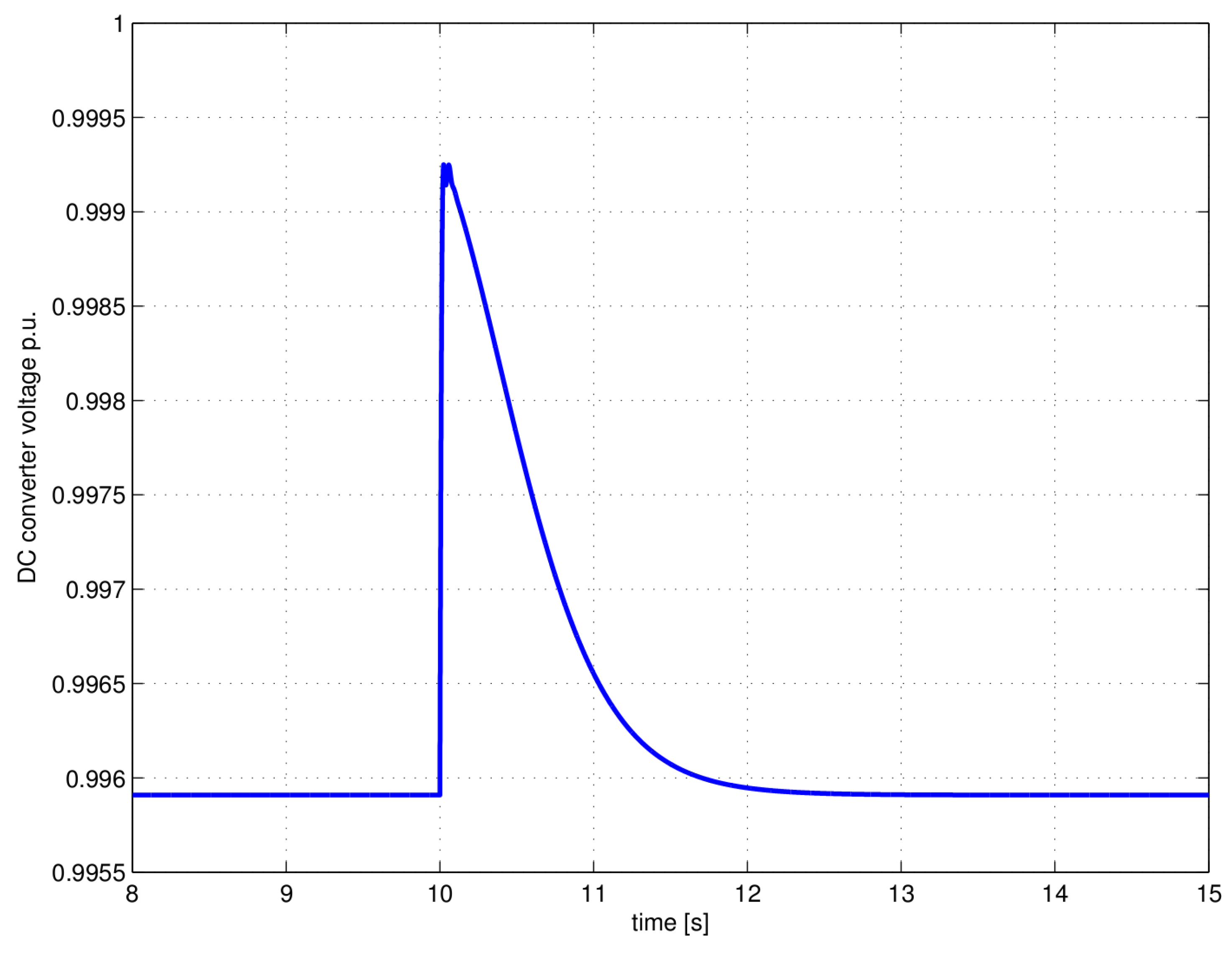
During the transient, there is an initial drop of the active power delivered by the converter. This is followed by a quick recovery action of the control system. As to be expected, at the beginning, the DC link voltage has a small increase (0.003 p.u.). After the control recovery, the voltage comes back to the initial value and is then kept constant, as shown in
Figure 14.
Figure 12.
Grid under-voltage and the corresponding current transient.
Figure 12.
Grid under-voltage and the corresponding current transient.
Figure 13.
Simulated transients of iD and iQ after the grid under-voltage.
Figure 13.
Simulated transients of iD and iQ after the grid under-voltage.
Figure 14.
DC Link voltage transient due to the grid under-voltage.
Figure 14.
DC Link voltage transient due to the grid under-voltage.
