Article

Advanced Thermodynamic Analysis and Evaluation of a Supercritical Power Plant

1
Institute for Advanced Energy System, North China Electric Power University, Beinong Road 2, Beijing 102206, China
2
Institut für Energietechnik, Technische Universität Berlin, Marchstr. 18, Berlin 10587, Germany
*
Author to whom correspondence should be addressed.
Energies 2012, 5(6), 1850-1863; https://doi.org/10.3390/en5061850
Submission received: 2 May 2012 / Revised: 18 May 2012 / Accepted: 31 May 2012 / Published: 15 June 2012
(This article belongs to the Special Issue Exergy Analysis of Energy Systems)

Abstract

:
A conventional exergy analysis can highlight the main components having high thermodynamic inefficiencies, but cannot consider the interactions among components or the true potential for the improvement of each component. By splitting the exergy destruction into endogenous/exogenous and avoidable/unavoidable parts, the advanced exergy analysis is capable of providing additional information to conventional exergy analysis for improving the design and operation of energy conversion systems. This paper presents the application of both a conventional and an advanced exergy analysis to a supercritical coal-fired power plant. The results show that the ratio of exogenous exergy destruction differs quite a lot from component to component. In general, almost 90% of the total exergy destruction within turbines comes from their endogenous parts, while that of feedwater preheaters contributes more or less 70% to their total exergy destruction. Moreover, the boiler subsystem is proven to have a large amount of exergy destruction caused by the irreversibilities within the remaining components of the overall system. It is also found that the boiler subsystem still has the largest avoidable exergy destruction; however, the enhancement efforts should focus not only on its inherent irreversibilities but also on the inefficiencies within the remaining components. A large part of the avoidable exergy destruction within feedwater preheaters is exogenous; while that of the remaining components is mostly endogenous indicating that the improvements mainly depend on advances in design and operation of the component itself.

1. Introduction

Nearly 45% of global electricity generation is derived from coal, while natural gas and nuclear energy make up about 20% and 15%, respectively [1,2]. Despite the rapid growth of cleaner sustainable energies, the heavily dependence of world energy on coal is expected to continue for decades. It has been well known that the supercritical coal-fired power plants are energy systems with high fuel consumption, low efficiency, and relatively large amounts of pollutants and greenhouse gas emissions. Consequently, efficiency improvements of both existing units and plants under construction are of particular importance.
Exergy analysis can identify the location, the magnitude, and the sources of thermodynamic inefficiencies in a thermal system [3], and thus provide information for improving the overall efficiency and the cost effectiveness of a system or for comparing the performance of various systems [4]. Throughout the last decades, this conventional exergy analysis has been discussed and applied to a wide variety of coal-fired power plants, for example, see [5,6,7,8,9]. However, conventional exergy analysis is always used to evaluate the performance of an individual component at certain operation conditions, without considering the interactions among components or the actual achievable best behavior of the component under investigation.
The advanced exergy analysis was proposed and developed in [10,11,12,13,14,15,16,17,18] to evaluate energy conversion systems by splitting the exergy destruction into endogenous/exogenous and avoidable/unavoidable parts, which are crucial for improving complex systems. Therefore, more comprehensive, practical and not just rigorous information on how and to what extend the components can be improved is provided by an advanced exergy analysis to explicitly develop strategies for system performance enhancement. In the last years, advanced exergy analyses have been successfully applied to many energy conversion systems including simple and complex systems. At first, systems such as a simple gas-turbine-based cogeneration system [11], a simple vapor-compression refrigeration machine [15], and a novel cogeneration system for vaporizing liquefied natural gas [17] were used for demonstrating the theory development and applications. Later applications include more complex systems such as a cogeneration power plant based on gas turbine [12], and a three-pressure level combined cycle [18]. The results of these applications show that considering the interactions among components and the energy-saving potentials makes the approach a promising and powerful tool for effectively improving complex energy systems, such as coal-fired power plants.
However, until now no supercritical coal-fired power plant has been analyzed and evaluated using this method. Hence in this paper both conventional and advanced exergy analyses were performed to an existing modern supercritical pulverized-coal power-generation unit, in order to formulate some recommendations for system improvement.

2. Methodology

2.1. Conventional Exergy Analysis

It is assumed that the system boundaries are at the temperature T0 of the reference environment, and therefore, there are no exergy losses associated with the kth component [19]. As a consequence, the exergy loss term actually only appears at the level of the overall system. Hence, the exergy balance of the kth component is expressed as:
E ˙ F , k   =   E ˙ P , k + E ˙ D , k
where subscripts F, P and D represent as fuel exergy, product exergy and exergy destruction within the considered component k, respectively.
For the overall system, it becomes:
E ˙ F , t o t   =   E ˙ P , t o t + k E ˙ D , k + E ˙ L , t o t
where the subscript tot means the total amount of the overall system.
The exergetic efficiency of the kth component ε k is written as:
ε k   =   E ˙ P , k E ˙ F , k   =   1 E ˙ D , k E ˙ F , k
To identify the part of total fuel exergy input destroyed within the kth component, the exergy destruction ratio y D , k is defined as:
y D , k   =   E ˙ D , k E ˙ F , k

2.2. Advanced Exergy Analysis

In an advanced exergy analysis, the exergy destruction within each component is split to better reveal its sources (endogenous/exogenous) and its potential for reduction (avoidable/unavoidable) [18]. The endogenous part is the exergy destruction obtained when all other components operate ideally and the component being considered operates with its real efficiency. The exogenous part of the exergy destruction within the considered component, is caused by irreversibilities in the remaining components and by the structure of the overall system, and is the difference between total exergy destruction of the component at real conditions and the endogenous part. The unavoidable part is the part that cannot be eliminated, even if the best available technology in the near future would be applied. Finally the avoidable part is the difference between the total exergy destruction within the component in the real plant and the unavoidable part of exergy destruction [15].

2.2.1. Endogenous/Exogenous Exergy Destruction

To consider the interactions among components, the exergy destruction within the kth component is expressed, as equation (5) shows, as the sum of endogenous and exogenous exergy destruction:
E ˙ D , k   =   E ˙ D , k E N + E ˙ D , k E X
where the superscripts EN and EX indicate the endogenous and exogenous parts, respectively.
Since it is also important, how and to what extend one component affects another component [17], the exogenous exergy destruction can be further split as:
E ˙ D , k E X   =   r   =   1 r k n E ˙ D , k E X , r + E ˙ D , k M X
where E ˙ D , k E X , r is the effect of exergy destruction within the rth component caused by the exergy destruction of the kth component. It can be seen that the total exogenous exergy destruction is comprised of two terms, a sum term and a term called mexogenous exergy destruction E ˙ D , k M X due to the simultaneous interactions of all other ( n 1 ) components.

2.2.2. Avoidable/Unavoidable Exergy Destruction

Due to technical and economic limitations and manufacturing methods, each component has an unapproachable best thermodynamic behavior in the near future that determines the unavoidable part of exergy destruction. When each component operates with its best possible conditions, the unavoidable process is established, to obtain the ratio ( E ˙ D / E ˙ P ) k U N for the component. This ratio is the key parameter for calculating the unavoidable part of exergy destruction of individual components in a real process. Therefore, the exergy destruction of the kth component can also be written as:
E ˙ D , k   =   E ˙ D , k U N + E ˙ D , k A V
where the superscripts UN and AV stand for the unavoidable and avoidable parts, and the unavoidable part can be calculated by:
E ˙ D , k U N   =   E ˙ P , k · ( E ˙ D / E ˙ P ) k U N

2.2.3. Combination of the splitting

By further combining the two splitting concepts, the avoidable-endogenous ( E ˙ D , k A V , E N )/avoidable-exogenous ( E ˙ D , k A V , E X ) and unavoidable-endogenous ( E ˙ D , k U N , E N )/unavoidable-exogenous ( E ˙ D , k U N , E X ) terms can be obtained by:
E ˙ D , k U N , E N   =   E ˙ P , k E N · ( E ˙ D / E ˙ P ) k U N
E ˙ D , k U N , E X   =   E ˙ P , k U N E ˙ D , k U N , E N
E ˙ D , k A V , E N   =   E ˙ P , k E N E ˙ D , k U N , E N
E ˙ D , k A V , E X   =   E ˙ P , k E X E ˙ D , k U N , E X
In order to calculate each part of the exergy destruction within all components, five sorts of processes including real, theoretical, hybrid I, hybrid II and unavoidable processes should be considered and simulated. In a theoretical process, all components operate under their theoretical conditions; while in a hybrid I process only the component being considered is set at its real condition to compute its endogenous exergy destruction. Simulations of totally ( n ( n 3 ) 2 ) hybrid II processes enable us to quantify the interaction between any two components operating under their real conditions with n being the total number of components. The unavoidable process where each component operates under its unavoidable conditions is simulated for obtaining the unavoidable ratios of all components.

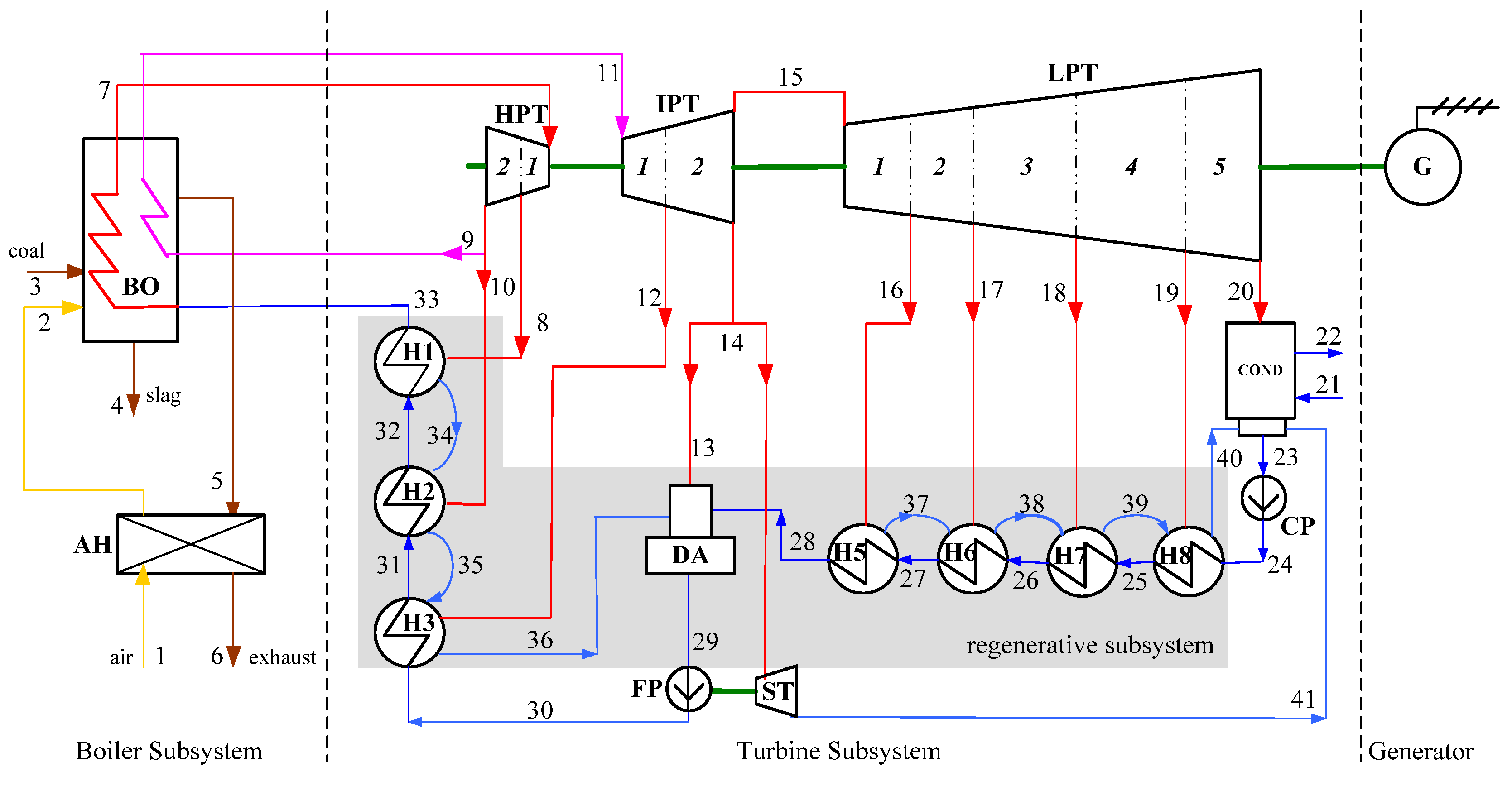
3. Plant Descriptions

The supercritical power plant, as shown in Figure 1, has a total installed power capacity of 671MW, consisting of a boiler subsystem and a turbine subsystem and an electrical generator. The properties of bituminous coal are listed in Table 1.
Figure 1. Schematic diagram of the overall supercritical power generation unit.
Energies 05 01850 g001
Table 1. Approximate analysis of coal (wt. %; as received).
ItemValueItemValueItemValueItemValue
Moisture2.10%Carbon57.52%Oxygen2.78%Sulphur2.00%
Ash23.70%Hydrogen3.11%Nitrogen0.99%LHV21981 kJ/kg
The boiler subsystem with dry ash extraction and single reheat is simulated by two components: boiler (BO) and air preheater (AH). The coal combustion process and the heat transfer between flue gas and working fluid occur in the boiler. In this way, the theoretical condition of boiler subsystem can be readily specified.
The main steam is expanded in the high-pressure turbine (HPT) and then the steam is reheated and expanded through the stages of intermediate-pressure (IPT) and low-pressure turbines (LPT). The HPT is considered in two parts the same with the splitting of IPT into IPT1 and IPT2: from the inlet to steam extraction (HPT1) and from steam extraction to outlet (HPT2). Similarly, the low-pressure turbine (LPT) is considered in five parts (LPT 1 through LPT5). A surface condenser (COND) is used to remove to the environment heat from exhausted steam. To increase the thermodynamic average temperature of the working fluid in the boiler, a feedwater regenerative system with three high-pressure heaters (H1-H3), four low-pressure heaters (H5-H8) and a deaerator (DA) is configured. The condensate pump (CP) and feedwater pump (FP) are driven by electric motors and a secondary steam turbine (ST) with the same steam supply as for the deaerator.
The simulation of the supercritical coal-fired power plant was conducted with the help of the software EBSILON Professional and the main thermodynamic parameters of each flow are listed in Table 2.
Table 2. Thermodynamic properties of all material flows.
No m , kg/s T , °C p , bar E ˙ t o t , MWNo m , kg/s T , °C p , bar E ˙ t o t , MW
1619.38525.001.0020.852229813.630.791.00081.39
2619.385330.411.00061.4023395.49735.790.0591.27
368.80225.001.0001603.0724395.49735.9417.241.96
415.980600.001.00015.9725395.49758.1615.844.41
5670.831394.000.998133.3926395.49785.4114.5410.46
6670.831127.000.97848.8527395.497105.0612.9416.63
7522.217571.00254.0806.9028395.497143.2411.4432.57
839.407364.2367.9746.8129522.217180.0610.0469.16
9438.914304.9843.00474.9430522.217185.59308.787.76
1043.896304.9843.0047.5031522.217211.95303.7109.57
11438.914569.0041.10632.4932522.217253.27298.4149.16
1219.400459.6820.5823.4533522.217284.05293.5183.29
1324.018362.6810.4424.203439.407258.8264.9711.05
1428.702362.6810.4428.923583.303217.5041.0016.41
15366.794362.6810.44369.5236102.702191.1419.0815.45
1625.599253.534.37420.123725.599110.614.1741.19
1712.993128.721.3337.013838.59290.961.3331.13
1817.28688.190.6557.273955.87863.710.6550.68
1913.57460.940.2083.414069.45241.490.2080.30
20297.34335.790.05923.804128.70239.680.0733.20
2129813.625.001.00074.47

4. Simulations for the Advanced Exergy Analysis

Defining the theoretical and unavoidable conditions of each component is the most important task for the calculation of different parts of exergy destruction. In this section, the theoretical and unavoidable conditions of different components of the energy system are discussed.

4.1. Theoretical Conditions

The theoretical operation conditions for each component should follow the assumptions: E ˙ D   =   0 , (if possible), or otherwise E ˙ D   =   m i n . With regards to the features of the power plant, many parameters in the theoretical process are the same as in the real process: for example, temperature and pressure of superheated steam, temperature of reheated steam, pressure levels of steam extractions, back pressure of turbine, and the inlet temperature of cooling water flowing into condenser remain unchanged when a component is under theoretical conditions. However, the temperature and pressure of feedwater into boiler, the pressure of reheated steam, the temperature of steam extraction as well as the outlet temperature of cooling water flowing out of the condenser always vary with the conditions assumed for the corresponding component.
For turbines, fans and pumps, both the isentropic efficiency ( η S ) and the mechanical efficiency ( η m ) should equal to unity to guarantee no exergy destruction during the corresponding process.
For heat exchangers, it is apparent that the working condition with no entropy generation is normally unachievable due to the existence of a pinch point ( Δ T p ). Only the state where the exergy destruction is minimal can be achieved by assuming no pressure drop ( Δ p ) and zero temperature difference at the pinch point.
The combustion process in this case is not considered separately but is integrated into the component boiler with the heat transfer process. However, there are still some assumptions referring to the combustion process for defining the theoretical conditions of the boiler: the combustion efficiency ( η c ) of coal is unity to make sure the complete combustion, the chemical composition of flue gas should be kept the same as in the real conditions to make sure that the excess air/fuel ratio (α) is equal to that of the real process, and no pressure drops to generate superheated mean steam ( Δ p s h ) and for reheat ( Δ p s h ) occurs to satisfy the theoretical conditions of combustion process. Detailed explanations are given in [13].

4.2. Unavoidable Conditions

The unavoidable conditions refer to the best unapproachable working conditions associated with the technical and economic limits related to the considered component. In general, it would be better if the best performance characteristics can be derived in conjunction with some kind of investment-efficiency curves or the best practice of the same type components under operation. If no such resources are available, the best behavior is determined more than less arbitrarily, depending highly on the understanding and practical experience of the analyzer. In this paper the unavoidable conditions of each component are chosen as listed in Table 3, where the upper ( Δ T u p ) and lower ( Δ T l o w ) approach temperature differences for feedwater preheaters are used instead of Δ T p , since for this kind of heater with fluid phase change it is not straightforward to specify the Δ T p . It should be mentioned here that the temperature of exhausted flue gas ( T e x ) selected as 90 °C, assuming that the utilization of low-grade heat of exhaust under the dewpoint can be realized in the near future.
Table 3. Assumptions of theoretical and unavoidable conditions *.
Comp.Real ProcessUnavoidable ProcessComp.Real ProcessUnavoidable Process
HPT1 η S = 0.89, η m = 0.998 η S = 0.92, η m = 1.0H7 Δ T u p = 2.9, Δ T l o w = 5.5 Δ T u p = 1.5, Δ T l o w = 3.0
HPT2 η S = 0.88, η m = 0.998 η S = 0.92, η m = 1.0H6 Δ T u p = 3.1, Δ T l o w = 5.5 Δ T u p = 1.5, Δ T l o w = 3.0
IPT1 η S = 0.92, η m = 0.998 η S = 0.96, η m = 1.0H5 Δ T u p = 6.3, Δ T l o w = 5.5 Δ T u p = 3.0, Δ T l o w = 3.0
IPT2 η S = 0.93, η m = 0.998 η S = 0.96, η m = 1.0DA Δ p = 0.4 Δ p = 0.1
LPT1 η S = 0.94, η m = 0.998 η S = 0.96, η m = 1.0FP η S = 0.84, η m = 0.998 η S = 0.87, η m = 1.0
LPT2 η S = 0.96, η m = 0.998 η S = 0.97, η m = 1.0H3 Δ T u p = 4.9, Δ T l o w = 5.5 Δ T u p = 3.0, Δ T l o w = 3.0
LPT3 η S = 0.92, η m = 0.998 η S = 0.94, η m = 1.0H2 Δ T u p = 3.0, Δ T l o w = 5.5 Δ T u p = 1.5, Δ T l o w = 3.0
LPT4 η S = 0.74, η m = 0.998 η S = 0.85, η m = 1.0H1 Δ T u p = 2.8, Δ T l o w = 5.5 Δ T u p = 1.5, Δ T l o w = 3.0
LPT5 η S = 0.82, η m = 0.998 η S = 0.85, η m = 1.0ST η S = 0.80, η m = 0.998 η S = 0.87, η m = 1.0
COND Δ T p = 5.0 Δ T p = 3.0GT η m = 0.986 η m = 0.998
CP η S = 0.80, η m = 0.998 η S = 0.87, η m = 1.0BO η c = 0.980, Δ p s h = 40.5 Δ p r h = 1.90, α = 1.2 η c = 0.995, Δ p s h = 20 Δ p r h = 0.50, α = 1.03
H8 Δ T u p = 2.9, Δ T l o w = 5.5 Δ T u p = 1.5, Δ T l o w = 3.0AH T e x = 127.0 T e x = 90.0
* units: η (-), T(°C), p(bar), α (-).

5. Results and Discussion

The results from the conventional and the advanced exergy analysis at the component level are summarized in Table 4 and Table 5.
Table 4. Results from the conventional exergy analysis at the component level.
Comp. E ˙ F , MW E ˙ P , MW y D , % ε , %Comp. E ˙ F ,MW E ˙ P , MW y D , % ε , %
HPT1186.55175.690.7294.2H77.726.050.1178.4
HPT251.1047.630.2393.2H67.076.170.0687.2
IPT1101.9998.20.2596.3H518.9315.930.2084.2
IPT284.4181.360.2096.4DA22.8619.810.2086.7
LPT181.2878.220.2096.2FP20.8018.60.1589.4
LPT283.9381.560.1697.2H324.4121.810.1789.4
LPT339.1336.50.1793.3H242.1439.60.1794.0
LPT452.6339.890.8575.8H135.7634.130.1195.4
LPT550.9441.950.6082.4ST25.7220.80.3380.9
COND26.03-1.27-GT681.00671.210.6598.6
CP0.860.690.0180.5BO1483.04781.1646.5752.7
H83.792.460.0964.8AH84.5460.551.5971.6
Table 5. Results of advanced exergetic analysis at the component level (Unit: MW).
Comp. E ˙ D , k E N E ˙ D , k E X E ˙ D , k U N E ˙ D , k A V E ˙ D , k E N E ˙ D , k E X
E ˙ D , k U N , E N E ˙ D , k A V , E N E ˙ D , k A V , E X E ˙ D , k U N , E X
HPT19.900.967.253.616.673.230.380.58
HPT23.050.422.161.311.871.180.130.29
IPT13.640.162.591.212.471.170.040.12
IPT22.690.372.041.011.770.920.090.28
LPT12.780.282.380.682.100.680.000.28
LPT22.130.241.920.461.650.48−0.020.26
LPT32.310.311.920.701.720.590.110.20
LPT411.461.296.286.465.725.740.720.56
LPT57.841.157.151.846.231.610.230.92
COND15.303.81------
CP0.150.020.120.050.100.040.010.01
H81.180.161.120.210.990.190.030.13
H71.210.461.410.261.150.060.200.26
H60.610.290.710.190.540.070.120.17
H52.170.832.470.532.020.150.380.45
DA2.031.022.890.162.12−0.090.250.78
FP1.700.501.720.491.340.370.120.38
H32.280.322.160.441.960.330.110.20
H21.580.961.990.551.450.130.420.54
H11.150.491.250.381.000.150.240.25
ST3.201.723.501.422.310.890.531.19
GT9.790.001.358.451.358.450.000.00
BO615.2086.68676.2925.60608.986.2319.3767.31
AH16.917.0911.4612.5311.565.347.19−0.10

5.1. Conventional Analysis

It is very clear from Table 4 that 45% of the total input fuel exergy is destroyed in the boiler due to coal combustion and heat transfer under high temperature differences. The air preheater, turbines and condenser follow with much lower values of exergy destruction. The regenerative subsystem has little exergy destruction, whereas the secondary turbine and the generator have relatively large exergy destruction value.
From the perspective of the conventional analysis, the greater the irreversibility in a component, the higher the priority for improvement must be for increasing the efficiency of the overall system. Hence, the boiler should be given the first priority for the reduction of total inefficiencies. Then, the air preheater, the first and the last two stages of turbine have relatively high priorities, because these components have large operational exergy destruction.

5.2. Advanced Analysis

5.2.1. Interactions among Components

To investigate how and to what extend one component exerts impact on another, each E ˙ D , k E X is calculated and listed in Table 6, which also contains the endogenous exergy destruction of each component. It is apparent that the interactions between different components can be positive or negative. The former indicates that the exergy destruction in the kth component increases with the introduction of additional irreversibilities in the rth component. On the contrary, the latter means that adding inefficiencies in the rth component contributes to a reduction of the exergy destroyed in the kth component. These two distinct impacts can be the results of mass flow changes or thermodynamic property variation of material flows flowing through the kth component due to the introduction of additional irreversibility in the rth component. For example, when evaluating the interaction between components IPT1 and H3, introducing irreversibility in H3 reduces the outlet temperature of feedwater. This requires more steam extraction in the following feedwater preheater H2. Since the total mass flow rate is kept almost unchanged, the mass flow of steam through IPT1 is reduced. However, the impact of thermodynamic inefficiency in boiler on IPT1 results from large flow property changes. For example, we can assume that the irreversibilities in the boiler increase because of an increase in the pressure drop in the reheater. If the pressure at the outlet of the first part of the intermediate-pressure turbine (IPT1) remains constant, then the steam temperature at that point will increase, leading to a reduction in the exergy destruction within IPT1. Thus, increasing the exergy destruction in the boiler (component r) leads to a reduction in the exergy destruction within the IPT1 (component k). This explains the negative sign related to the interaction between these two components (see Table 6, third row and second to last column).
The exergy destruction within each turbine stage is mainly affected by the other stages, especially the stages with large irreversibility, the directly-connected feedwater preheater as well as the electrical generator. The irreversibilities in other turbine stages all have contributions to the exergy destruction in the considered turbine stage, whereas the inefficiencies of its corresponding feedwater preheater have a negative influence (negative sign in Table 6) on it due to the change of mass flow rate. In addition, the generator greatly affects the exergy destruction of each turbine stage, when the total generated power, as assumed here, remains constant.
With its constant pressure, the condenser has no effect on other components but its own exergy destruction greatly depends on other components, especially the turbine, secondary turbine, generator and the boiler. Good performance of these components can reduce the mass flow of main steam.
The pumps, condensate and feedwater pumps, are almost independent of all other components with the exception of the interaction between feedwater pump and boiler, since the pressure drop in boiler directly determines the pressure head provided by feedwater pump.
Although the regenerative subsystem is affected by the irreversibilities in turbine, the effects tend to be rather small. The performance of each feedwater preheater mostly relies on its preceding component. Hence, performance the enhancement of the feedwater heating system requires the best possible better operation conditions of all preheaters.
The components secondary turbine, feedwater pump, turbine, feedwater preheater and air preheater have a large effect on the boiler. The interaction between boiler and air preheater is intensive, thus, these components should be optimized as one unit.

5.2.2. Endogenous/Exogenous Exergy Destruction

Table 5 shows that a large part of the exergy destruction in all components is endogenous. However, for different types of components, the proportions of exogenous part differ significantly. All the exergy destruction in generator is endogenous. Nearly 10% of exergy destructions of turbine stages are considered as exogenous, while the average ratio of exogenous part in the regenerative system almost reaches 30%, which indicates that the effect of system topology contributes largely to their exergy destruction. The boiler, air preheater and condenser are the three components with the largest absolute exogenous destruction values especially that of boiler reaching 86 MW. In addition, all the exogenous exergy destructions are positive which means that the performance of any component improves with the performance enhancement of the remaining system components.
Table 6. Endogenous exergy of component k and the exogenous part caused by component r (MW).
krHPT1HPT2IPT1IPT2LPT1LPT2LPT3LPT4LPT5CONDCPH8H7H6H5DAFPH3H2H1STGEBOAH
HPT19.900.080.060.040.040.030.040.180.120.000.000.010.000.010.010.000.030.040.03−0.090.060.150.050.00
HPT20.143.050.020.010.010.010.010.050.040.000.000.000.000.000.000.000.010.02−0.030.000.020.040.020.00
IPT10.100.033.640.020.020.010.010.070.050.000.000.000.000.000.000.000.01−0.05−0.010.010.020.05−0.210.00
IPT20.080.020.022.690.010.010.010.050.030.000.000.000.000.000.00−0.010.010.000.000.010.010.040.020.00
LPT10.080.020.030.022.780.010.010.050.030.000.000.000.000.00−0.030.00−0.010.000.000.01−0.020.040.010.00
LPT20.060.020.030.020.022.130.010.040.030.000.000.000.00−0.010.000.00−0.010.000.000.01−0.020.030.010.00
LPT30.070.020.030.020.020.022.310.040.030.000.000.00−0.010.000.010.00−0.010.000.000.01−0.020.030.010.00
LPT40.330.100.150.110.110.080.0911.460.140.000.00−0.06−0.010.010.030.01−0.060.020.010.04−0.100.170.060.00
LPT50.230.070.100.080.070.060.060.317.840.000.00−0.010.010.010.020.00−0.040.010.000.03−0.070.110.040.00
COND0.430.130.180.130.140.100.110.570.3915.300.000.030.010.020.030.010.160.030.010.030.300.220.240.00
CP0.000.000.000.000.000.000.000.000.000.000.150.000.000.000.000.000.000.000.000.000.000.000.000.00
H80.030.010.010.010.010.010.010.020.020.00−0.011.180.000.000.000.000.010.000.000.000.010.020.010.00
H70.040.010.010.010.010.000.010.020.020.000.000.251.210.000.000.000.010.000.000.000.010.020.010.00
H60.020.010.010.000.000.000.000.010.010.000.000.000.170.610.000.000.000.000.000.000.000.010.010.00
H50.060.020.050.040.040.000.010.040.030.000.000.000.000.302.170.000.010.000.000.010.010.030.040.00
DA0.060.020.040.03−0.010.010.010.040.020.000.00−0.04−0.03−0.060.622.030.00−0.020.000.000.010.030.040.00
FP0.050.010.010.010.010.010.010.030.020.000.000.000.000.000.000.011.700.010.00−0.010.010.020.270.00
H30.060.020.080.010.010.010.010.040.030.000.000.000.000.000.000.18−0.122.28−0.05−0.010.010.030.000.00
H20.090.03−0.010.010.010.010.010.030.020.000.000.000.000.000.00−0.030.020.611.58−0.030.010.02−0.010.00
H10.070.000.010.010.010.000.000.020.010.000.000.000.000.000.000.000.00−0.020.221.150.010.020.000.00
ST0.090.030.020.010.010.010.010.060.040.000.000.000.000.000.000.000.630.010.01-0.033.200.050.500.00
GE0.000.000.000.000.000.000.000.000.000.000.000.000.000.000.000.000.000.000.000.000.009.790.000.00
BO7.002.113.392.632.662.032.2110.937.480.00−0.010.330.230.300.640.121.840.32−0.041.373.678.98615.2019.25
AH0.260.070.100.070.070.060.060.300.210.000.000.010.010.010.020.000.040.010.03−0.200.090.254.7416.91

5.2.3. Unavoidable/Avoidable Exergy Destruction

The real potential for improving a component is not fully revealed by its total exergy destruction but by its avoidable part. With the exception of boiler, 20%–40% of exergy destruction of the most components can be generally avoided with that part of the exergy destruction of generator and air preheater reaching 86% and 50%, respectively. The energy-savings potential from the generator also should call for attention, since the work saved is pure exergy and even a slight change of its efficiency contributes largely to total fuel consumption. Moreover, if the combustion process is stable and fulfils a much higher burnout rate under even lower oxygen ratio, and the temperature of flue gas exhaust would further decline to around 90 °C, which is now allowed due to the development of acid-resistant materials, up to 38 MW of exergy could be saved just in the boiler. Finally, the potential in other components such as the secondary turbine should also be emphasized.

5.2.4. Combined Analysis

The boiler subsystem has the largest avoidable exergy destruction; however, most of it is exogenous. For boiler the avoidable/endogenous part is slightly less than 25% of total avoidable part, while that of air preheater achieves nearly 45%. This indicates that the strategy for reducing the exergy destruction within the boiler should focus more on the components with a large effect on the boiler, such as turbine, secondary turbine and the last feedwater preheater. The irreversibilities occurring in air preheater itself and boiler have a similar contribution to the total avoidable exergy destruction within air preheater. To improve the air preheater, the entire boiler subsystem should be considered.
The generator also has a large amount of avoidable/endogenous exergy destruction, reaching almost 9 MW. The performance enhancement of this component in isolation can have great benefits to the reduction of overall fuel consumption. More or less 90% of avoidable exergy destruction of turbines is endogenous, which indicates the improvement measurements for turbines should be concentrated on the components themselves.

5.3. Improvement Strategy

Considering both the interactions among components and the potential for improving components, more effective and efficient improvement priorities can be proposed. The generator should be the first component to be enhanced in a separate way. Then, the turbines with high endogenous avoidable exergy destruction should also be improved separately. Subsequently, the measurements for enhancing feedwater regeneration subsystem with high proportion of exogenous avoidable exergy destruction should be concentrated on its subsystem level, since each individual preheater is mainly affected by its preceding one. The separate enhancement of only one feedwater preheater actually contributes little to the reduction of overall subsystem energy consumption. Finally, the boiler and air preheater can be improved by reducing both their inherent irreversibilities and the inefficiencies in the components with large contribution to their total exergy destruction, mainly the generator, turbines, last high-pressure feedwater preheater as well as feedwater pump. Given the combustion mode and boiler configuration, the effective approach for reducing fuel consumption is the combustion optimization with low air ratio and a further decrease of the exhaust gas temperature but not the rearrangement of heating surface configuration.

6. Conclusions

Exergy destruction in each component calculated in conventional exergy analysis is split, according to the sources and controllability. Considering detailed interactions among components and real potentials for improving components, the following conclusions can be obtained:
  • The ratio of exogenous exergy destruction differs quite a lot from component to component. In general, inherent irreversibilities in turbines contribute more or less 90% to their total exergy destruction, while this proportion drops down to 70% when it comes to feedwater preheaters. The boiler subsystem also has a large amount of exergy destruction caused by the inefficiencies in other components.
  • The boiler subsystem still has the largest avoidable exergy destruction; however, the enhancement efforts should be made not only to its inherent irreversibilities but also to inefficiencies of the remaining components. Moreover, around 60% of the avoidable exergy destruction of feedwater preheaters is exogenous. For the remaining components efforts should mainly focus on improving the components themselves.
  • Due to the interactions among components, the improvement priorities refer not only to the components that should be modified, but also to the sequence for optimization. We believe that the improvement of the boiler subsystem will be more meaningful if the remaining important components are improved first and can provide persuading good performances.

Acknowledgments

Ligang Wang and Yongping Yang would like to thank China 973 Project “Tempo-Spatial Distribution of Energy Consumption, Evaluation Method and System Integration for Large-scale Coal-fired Power Generation Unit” (2009CB219801), National Science Fund for Distinguished Young Scholars (51025624) and National nature Science Fund of China (51006034) for the financial supports.

References

  1. Energy Information Administration (EIA). International Energy Annual Website. Available online: http://www.eia.doe.gov/iea (accessed on 10 September 2011).
  2. Som, S.K.; Datta, A. Thermodynamic irreversibilities and exergy balance in combustion processes. Prog. Energy Combut. Sci. 2008, 34, 351–376. [Google Scholar] [CrossRef]
  3. Tsatsaronis, G.; Cziesla, F. Thermoeconomics. In Encyclopedia of Physical Science and Technology; Meyers, R.A., Ed.; Academic Press: New York, NY, USA, 2001; pp. 659–680. [Google Scholar]
  4. Bejan, A.; Tsatsaronis, G.; Moran, M. Thermal Design and Optimization; Wiley: New York, NY, USA, 1996. [Google Scholar]
  5. Rosen, M.A. Energy and exergy-based comparison of coal-fired and nuclear steam power plants. Exergy Int. J. 2001, 1, 180–192. [Google Scholar] [CrossRef]
  6. Sengupta, S.; Datta, A.; Duttagupta, S. Exergy analysis of a coal-based 210 MW thermal power plant. Int. J. Energy Res. 2007, 31, 14–28. [Google Scholar] [CrossRef]
  7. Aljundi, I.H. Energy and exergy analysis of a steam power plant in Jordan. Appl. Therm. Eng. 2009, 29, 324–328. [Google Scholar] [CrossRef]
  8. Ameri, M.; Ahmadi, P.; Hamidi, A. Energy, exergy and exergoeconomic analysis of a steam power plant: A case study. Int. J. Energy Res. 2009, 33, 499–512. [Google Scholar] [CrossRef]
  9. Regulagadda, P.; Dincer, I.; Naterer, G.F. Exergy analysis of a thermal power plant with measured boiler and turbine losses. Appl. Therm. Eng. 2010, 30, 970–976. [Google Scholar] [CrossRef]
  10. Tsatsaronis, G.; Morosuk, T. A General Exergy-Based Method for Combining a Cost Analysis with an Environmental Impact Analysis, Part I—Theoretical Development. In Proceedings of ASME 2008 International Mechanical Engineering Congress and Exposition (IMECE 2008), Boston, MA, USA, 2–6 November 2008.
  11. Tsatsaronis, G.; Morosuk, T. A General Exergy-Based Method for Combining a Cost Analysis with an Environmental Impact Analysis, Part II—Application to a Cogeneration System. In Proceedings of ASME 2008 International Mechanical Engineering Congress and Exposition (IMECE 2008), Boston, MA, USA, 2–6 November 2008.
  12. Kelly, S. Energy System Improvements Based on Endogenous and Exogenous Exergy Destruction. Ph.D. Thesis, Technische Universitat Berlin, Berlin, Germany, 2008. [Google Scholar]
  13. Morosuk, T.; Tsatsaronis, G. Advanced exergy analysis for chemically reacting systems—Application to a simple open gas-turbine system. Int. J. Thermodyn. 2009, 12, 105–111. [Google Scholar]
  14. Kelly, S.; Tsatsaronis, G.; Morosuk, T. Advanced exergetic analysis: Approaches for splitting the exergy destruction into endogenous and exogenous parts. Energy 2009, 34, 384–391. [Google Scholar] [CrossRef]
  15. Morosuk, T.; Tsatsaronis, G. Advanced exergetic evaluation of refrigeration machines using different working fluids. Energy 2009, 34, 2248–2258. [Google Scholar] [CrossRef]
  16. Petrakopoulou, F.; Tsatsaronis, G.; Morosuk, T. Conventional and Advanced Exergetic Analysis Applied to a Combined Cycle Power Plant. In Proceedings of 2010 International Conference on Efficiency, Cost, Optimization, Simulation and Environmental Impact of Energy Systems (ECOS 2010), Lausanne, Switzerland, 14–17 June 2010.
  17. Tsatsaronis, G.; Morosuk, T. Advanced exergetic analysis of a novel system for generating electricity and vaporizing liquefied natural gas. Energy 2010, 35, 820–829. [Google Scholar] [CrossRef]
  18. Petrakopoulou, F.; Tsatsaronis, G.; Morosuk, T.; Carassai, A. Advanced Exergoeconomic Analysis: Applied to a Complex Energy Conversion System. In Proceedings of ASME 2010 International Mechanical Engineering Congress and Exposition (IMECE 2010), Vancouver, Canada, 12–18 November 2010.
  19. Tsatsaronis, G. Design Optimization Using Exergoeconomic. In Thermodynamic Optimization of Complex Energy Systems; Bejan, A., Mamut, E., Eds.; Kluwer Academic Publishers: Dordrecht, The Netherlands, 1999; pp. 101–117. [Google Scholar]

