Analysis of Transient Phenomena Due to a Direct Lightning Strike on a Wind Energy System

Abstract
:1. Introduction
- wind turbines are tall structures of more than 150 m in height;
- wind turbines are frequently placed at locations very exposed to lightning;
- the most exposed wind turbine components such as blades and nacelle cover are often made of composite materials incapable of sustaining direct lightning stroke or of conducting lightning current;
- the blades and nacelle are rotating;
- the lightning current has to be conducted through the wind turbine structure to the ground, whereby significant parts of the lightning current will pass through or near to practically all wind turbine components;
- wind turbines in wind farms are electrically interconnected and often placed at locations with poor grounding conditions.
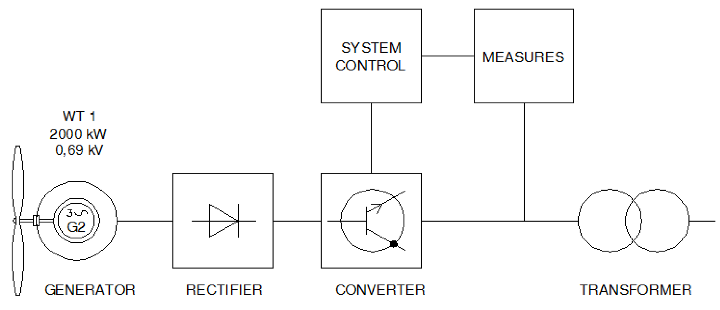
2. Wind Turbine Description
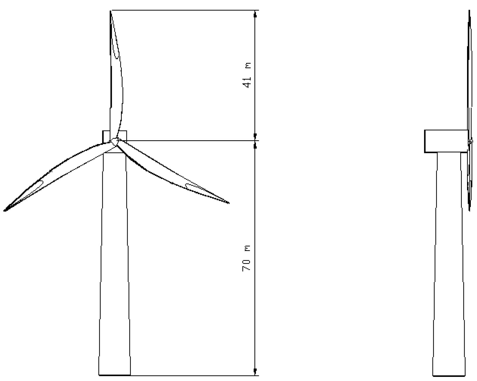

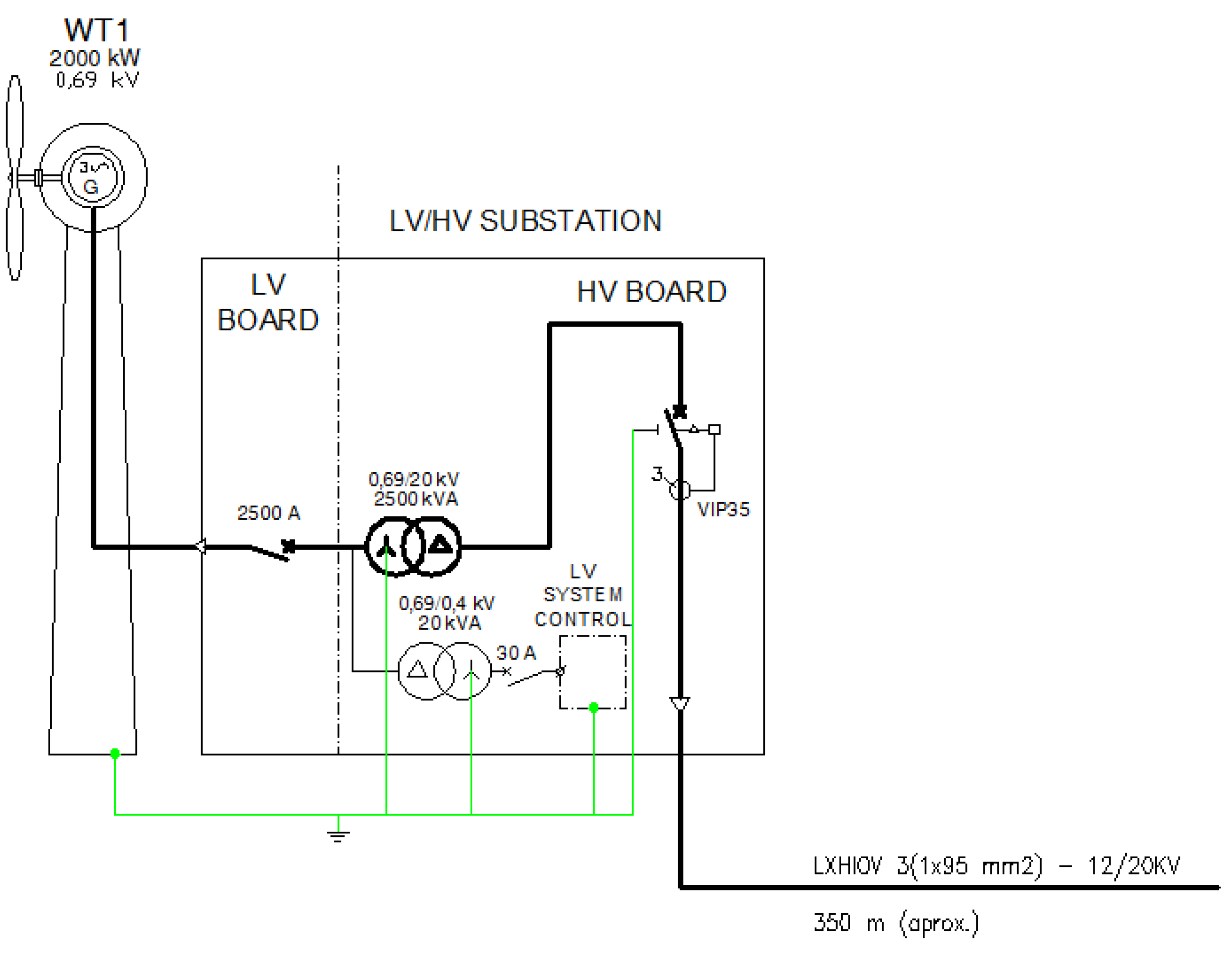
- a 690 V synchronous generator, sufficiently stable at 50 Hz, is considered;
- a 690 V/20 kV boost transformer is placed inside the wind turbine or installed rather close to the wind turbine; joint grounding of the primary and secondary side is assumed;
- the transformer model considers only electromagnetic transfer, considering surges only with relatively long periods exceeding 100 µs; the static transfer is ignored;
- the interconnection to the power grid is through a 20/60 kV transformer;
- the grounding resistance considered for the electrode in the absence of lightning currents is 1 Ω.
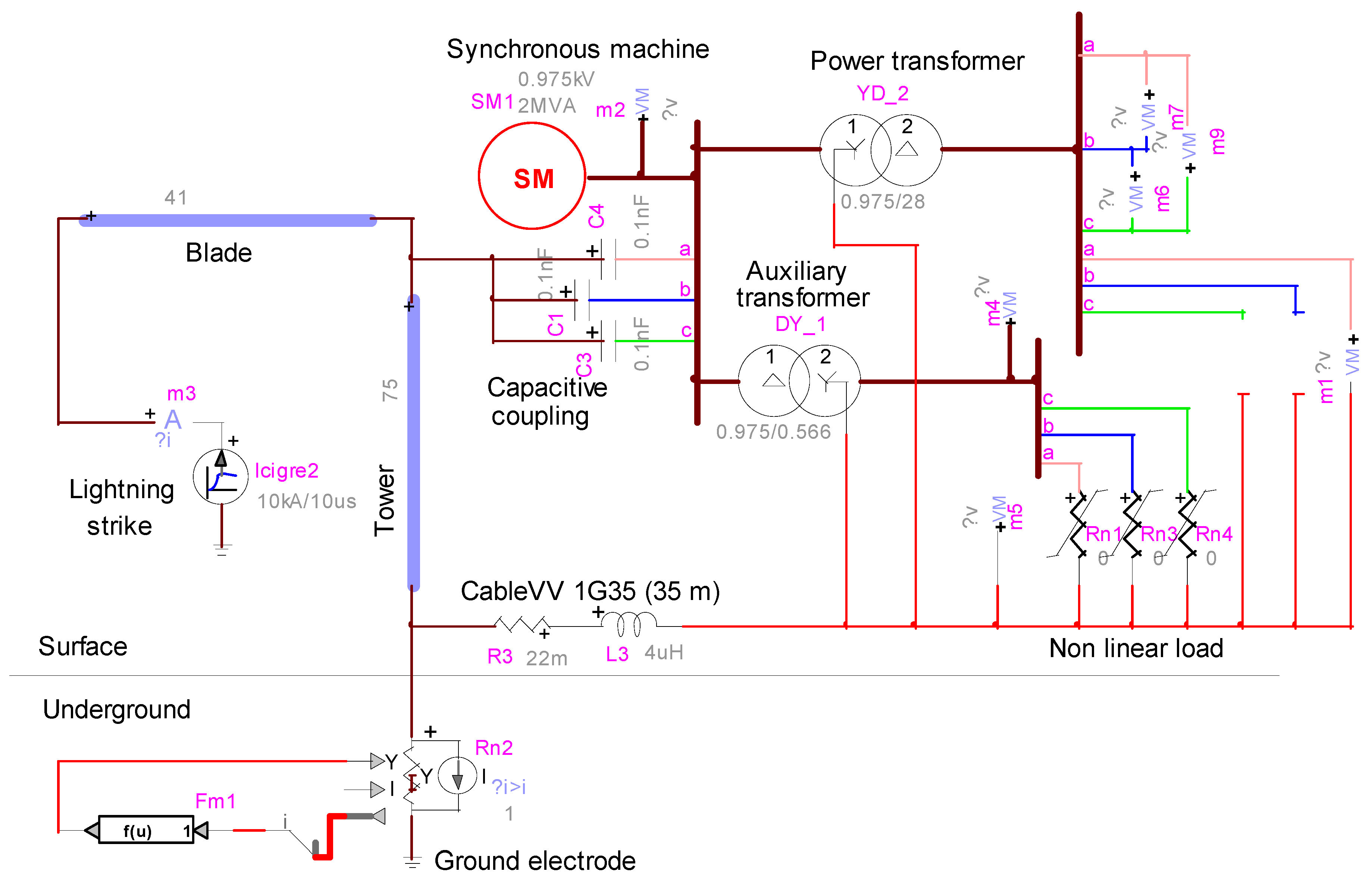
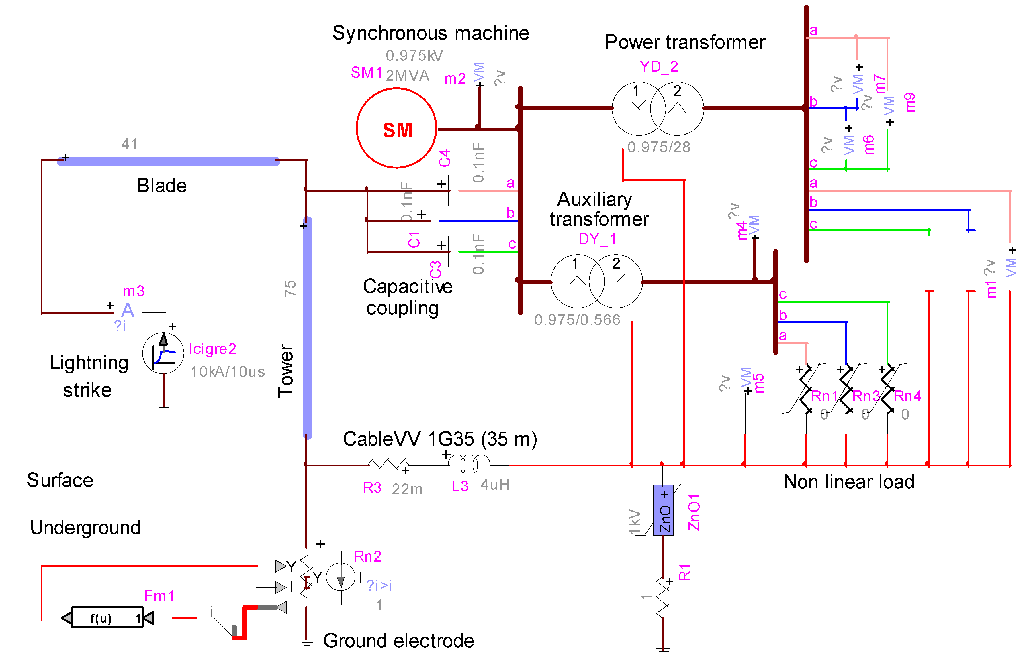
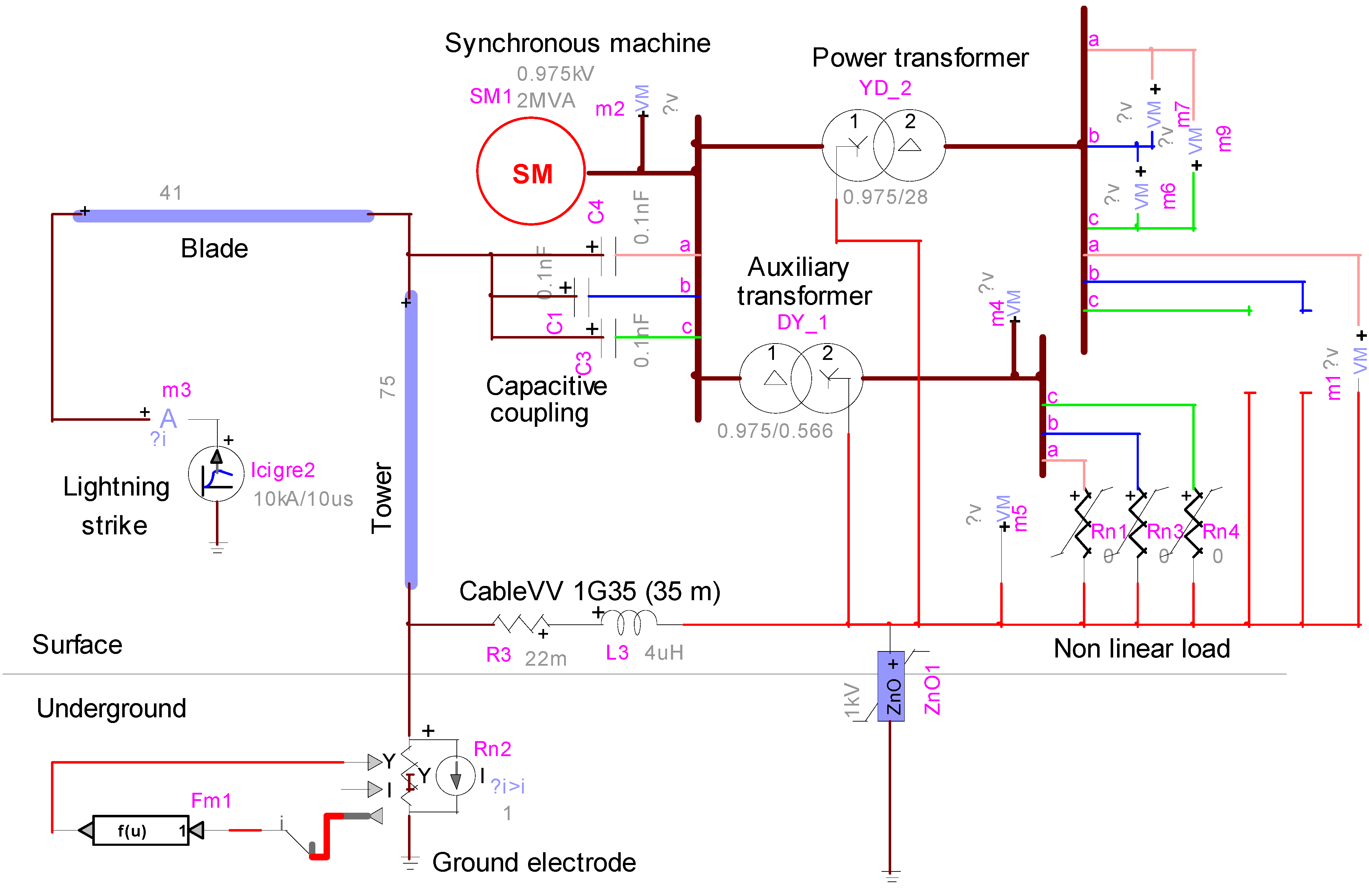
3. System Modeling
3.1. Lightning Current Source
3.2. Wind Turbine Structure
3.3. Ground Electrode
- the soil ionization in the immediate proximity of the grounding electrode, which is related to the current pulse intensity;
- the lightning pulse propagation along the grounding electrode, which is related to the current pulse front time.
3.4. Surge Arrester
3.5. Transformers
3.6. Capacitive Coupling
3.7. Nonlinear Load
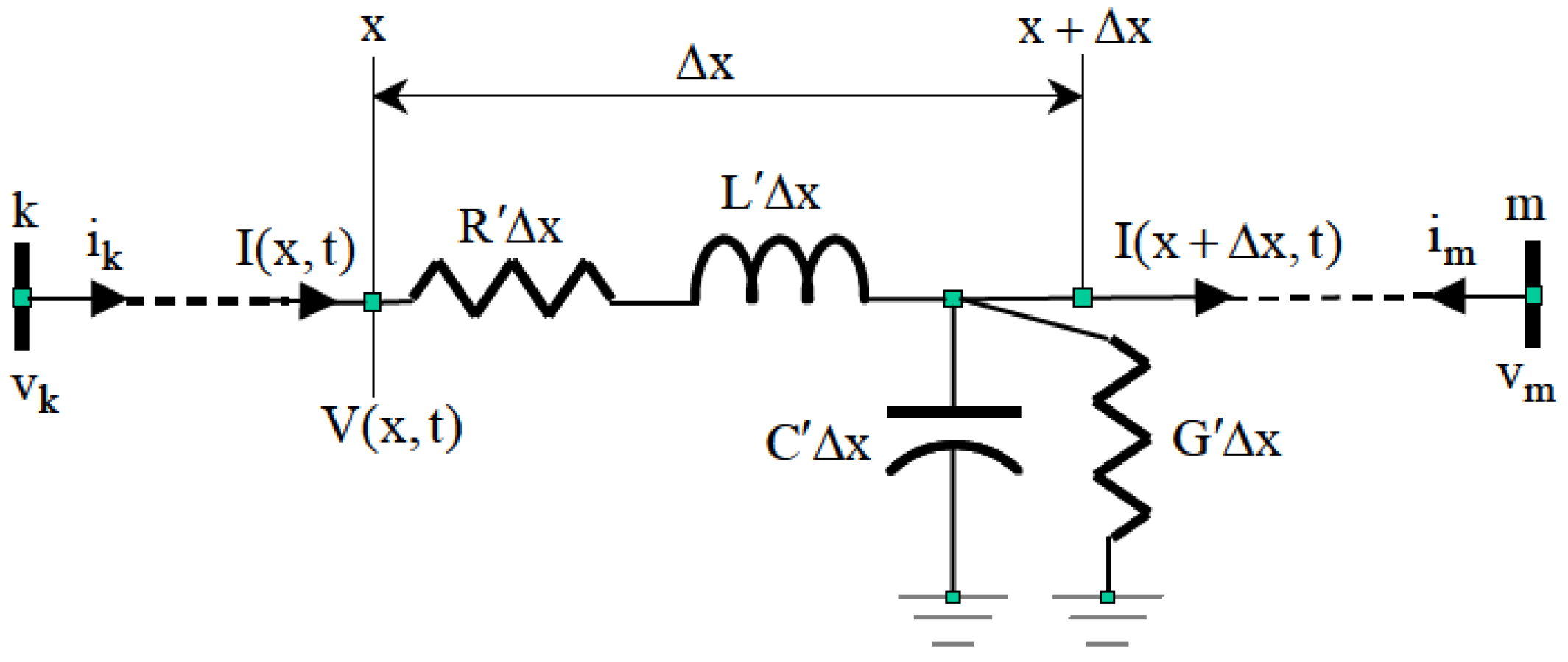
3.8. Cable Model
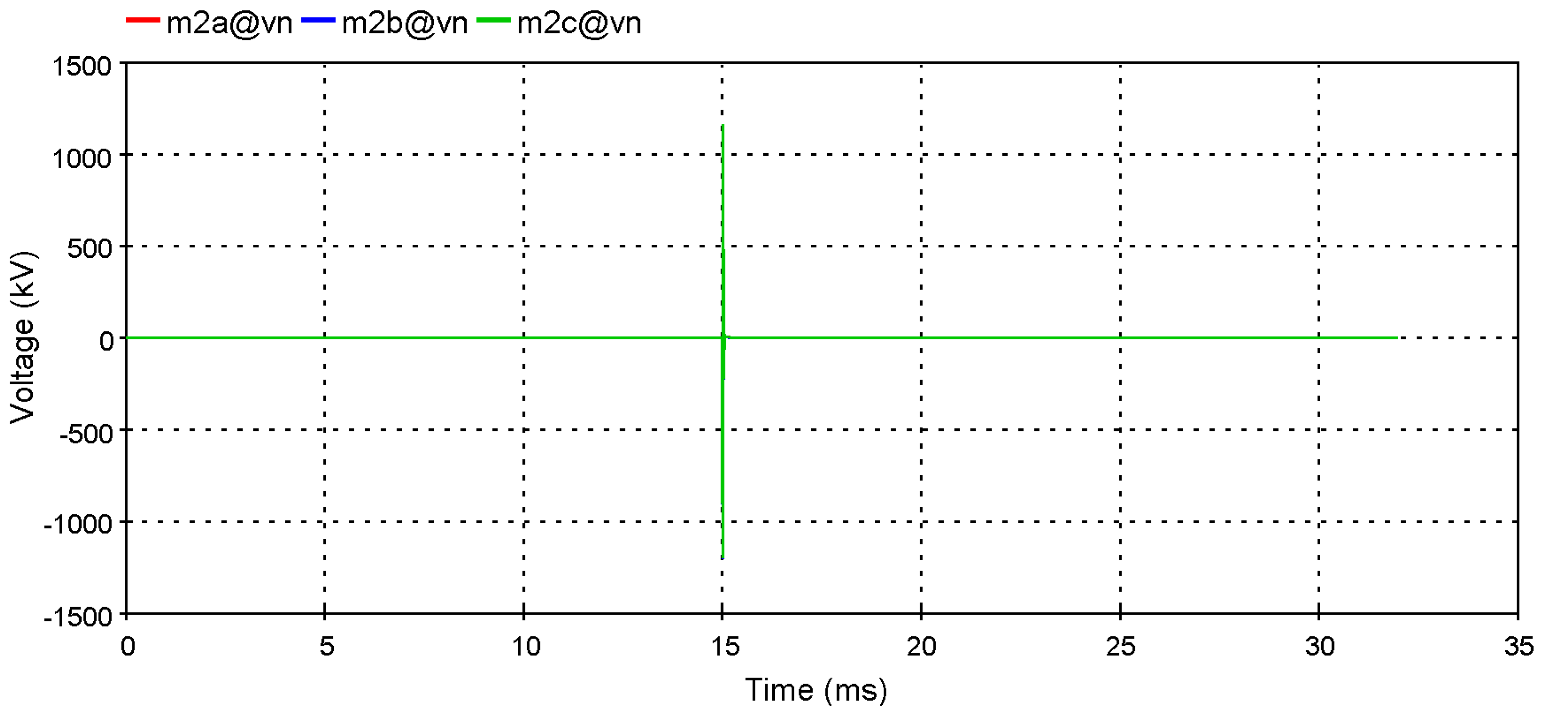
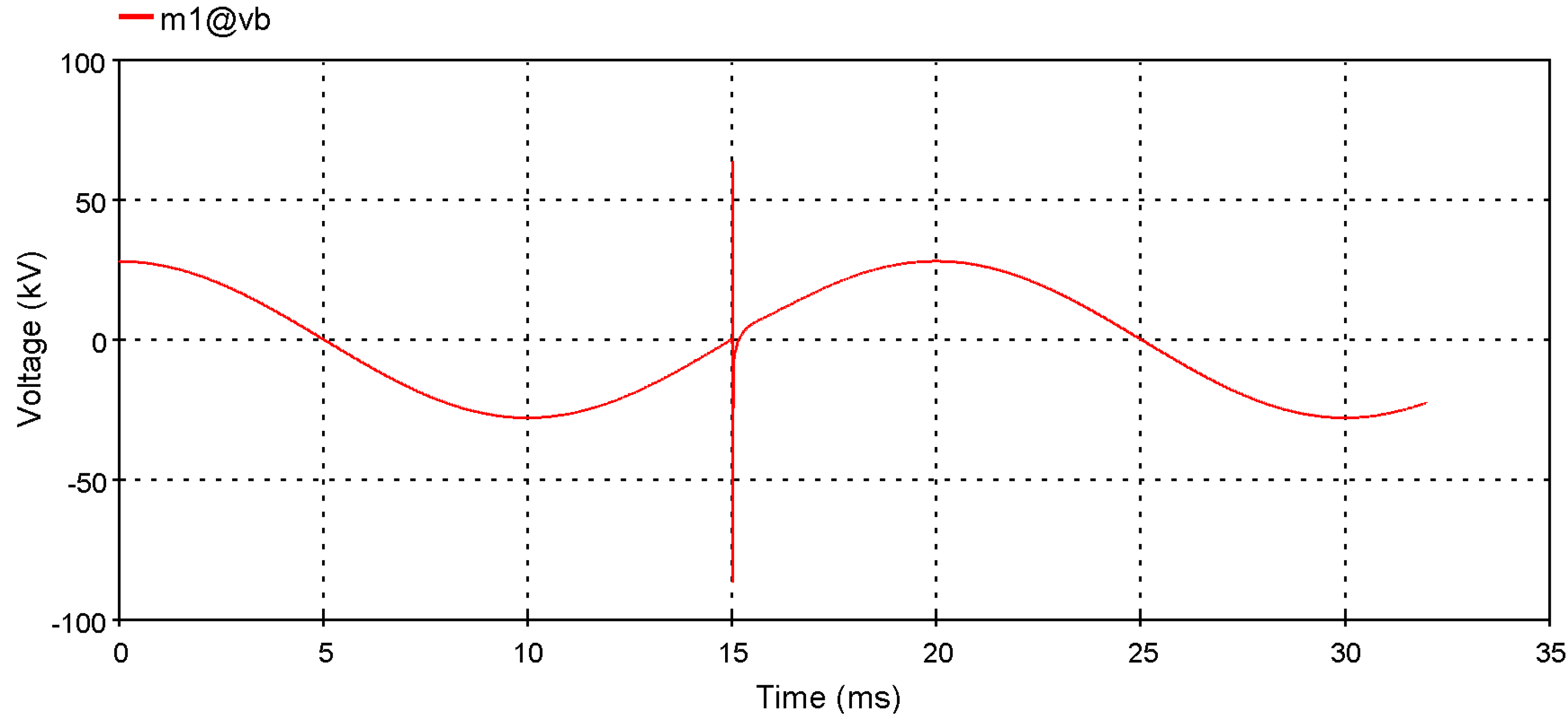
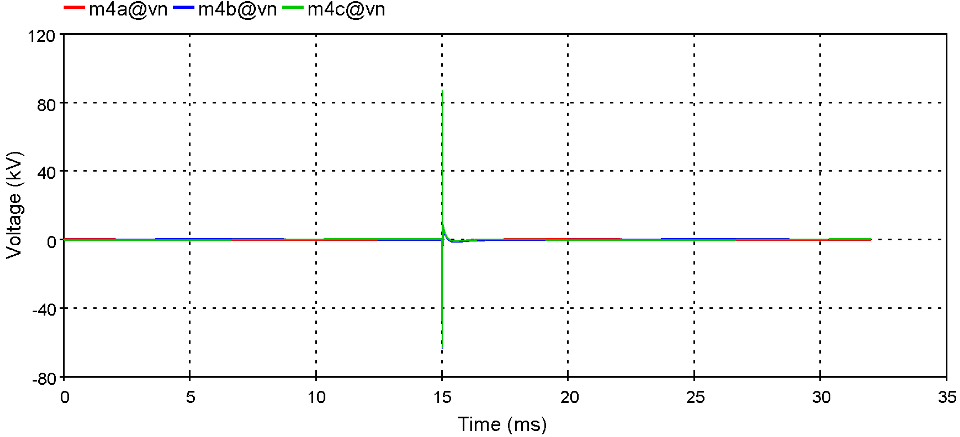
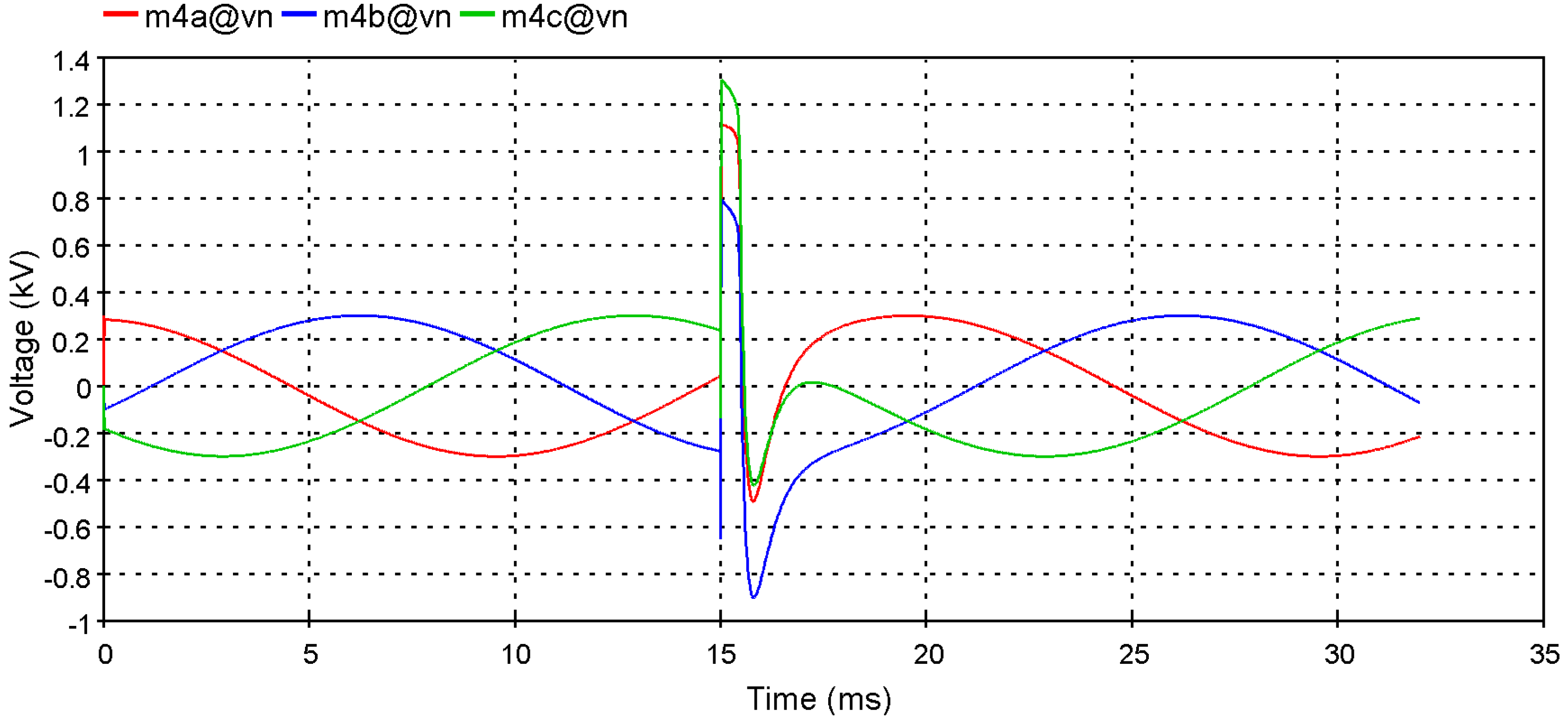
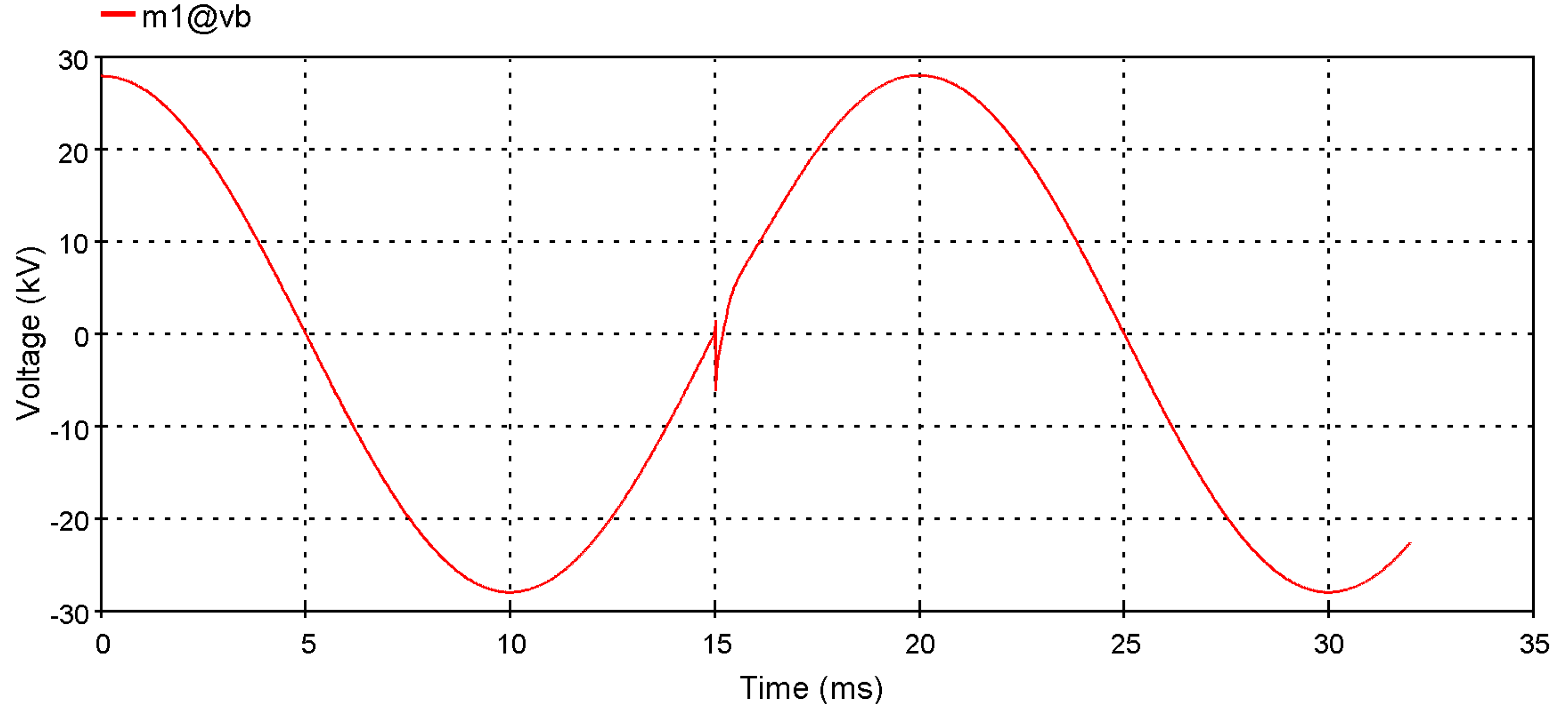
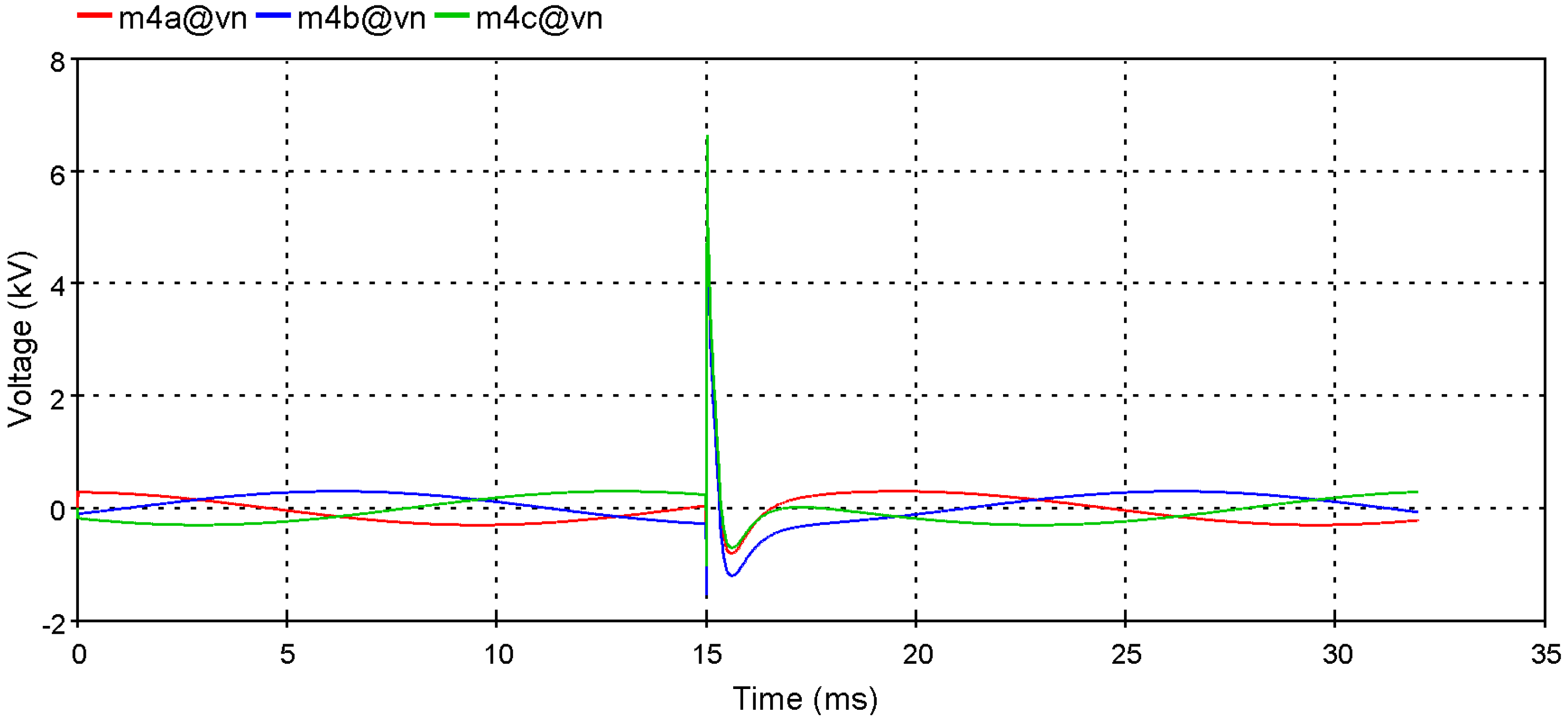
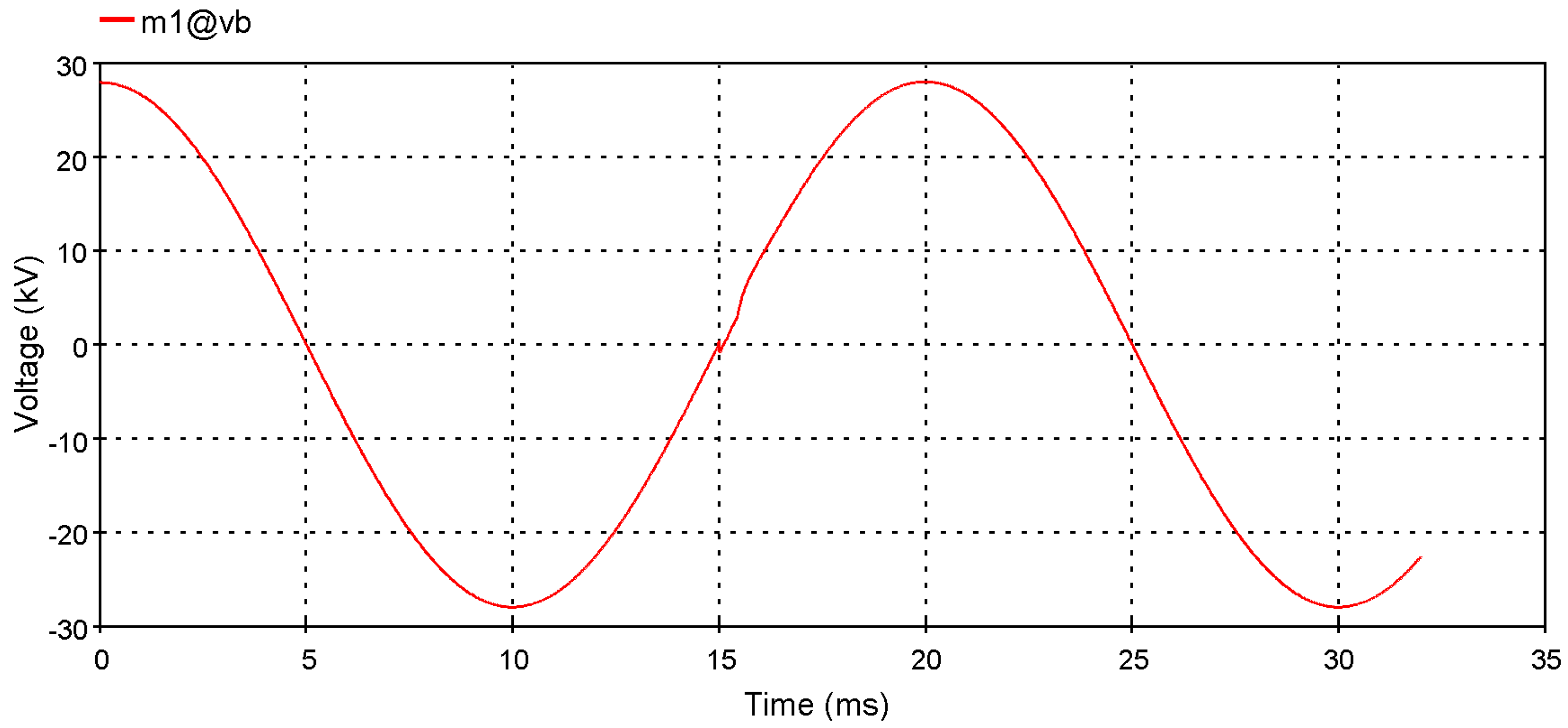
4. Simulation Results


5. Conclusions
Acknowledgments
References
- Leon-Martinez, V.; Montanana-Romeu, J. Analysis of wind generator operations under unbalanced voltage dips in the light of the Spanish grid code. Energies 2011, 4, 1148–1162. [Google Scholar] [CrossRef]
- Kang, H.Y.; Hung, M.C.; Pearn, W.L.; Lee, A.H.I.; Kang, M.S. An integrated multi-criteria decision making model for evaluating wind farm performance. Energies 2011, 4, 2002–2026. [Google Scholar] [CrossRef]
- Sarajcev, P.; Goic, R. A review of current issues in state-of-art of wind farm overvoltage protection. Energies 2011, 4, 644–668. [Google Scholar] [CrossRef]
- Wind Turbine Generator Systems—Part 24: Lightning Protection; Technical Report IEC TR 61400-24; International Electrotechnical Commission (IEC): Geneva, Switzerland, 2002.
- Rachidi, F.; Rubinstein, M.; Montanya, J.; Bermudez, J.-L.; Rodriguez Sola, R.; Sola, G.; Korovkin, N. A review of current issues in lightning protection of new-generation wind turbine blades. IEEE Trans. Ind. Electron. 2008, 55, 2489–2496. [Google Scholar] [CrossRef]
- Yasuda, Y.; Hara, T.; Funabashi, T. Analysis of lightning surge propagation in wind farm. Electr. Eng. Jpn. 2008, 162, 30–38. [Google Scholar] [CrossRef]
- Rodrigues, R.B.; Mendes, V.M.F.; Catalão, J.P.S. Protection of wind energy systems against the indirect effects of lightning. Renew. Energy 2011, 36, 2888–2896. [Google Scholar] [CrossRef]
- Cotton, I.; Jenkins, N.; Pandiaraj, K. Lightning protection for wind turbine blades and bearings. Wind Energy 2011, 4, 23–37. [Google Scholar] [CrossRef]
- Sorensen, T.; Jensen, F.V.; Raben, N.; Lykkegaard, J.; Saxov, J. Lightning Protection for Offshore Wind Turbines. In Proceedings of the 16th International Conference and Exhibition on Electricity Distribution, Amsterdam, The Netherlands, 18–21 June 2001; Volume 4, p. 5.
- Kern, A.; Krichel, F. Considerations about the lightning protection system of mains independent renewable energy hybrid-systems—practical experiences. J. Electrost. 2004, 60, 257–263. [Google Scholar] [CrossRef]
- Paolone, M.; Napolitano, F.; Borghetti, A.; Nucci, C.A.; Marzinotto, M.; Fiamingo, F.; Mazzetti, C.; Dellago, H. Models of Wind-Turbine Main Shaft Bearings for the Development of Specific Lightning Protection Systems. In Proceedings of the Power Tech 2007 Conference, Lausanne, Switzerland, 1–5 July 2007.
- Yasuda, Y.; Uno, N.; Kobayashi, H.; Funabashi, T. Surge analysis on wind farm when winter lightning strikes. IEEE Trans. Energy Convers. 2008, 23, 257–262. [Google Scholar] [CrossRef]
- Yasuda, Y.; Funabashi, T. Transient Analysis on Wind Farm Suffered from Lightning. In Proceedings of the 39th International Universities Power Engineering Conference, Bristol, UK, 8 September 2004; Volume 1, pp. 202–206.
- Piantini, A.; Janiszewski, J.M.; Borghetti, A.; Nucci, C.A.; Paolone, M. A scale model for the study of the LEMP response of complex power distribution networks. IEEE Trans. Power Deliv. 2008, 22, 710–720. [Google Scholar] [CrossRef]
- Yamamoto, K.; Noda, T.; Yokoyama, S.; Ametani, A. Experimental and analytical studies of lightning overvoltages in wind turbine generator systems. Electr. Power Syst. Res. 2009, 79, 436–442. [Google Scholar] [CrossRef]
- Mahseredjian, J.; Dewhurst, C. Using EMTP Tutorials and Reference; Hydro-Québec/IREQ: Montreal, Canada, 2008. [Google Scholar]
- Rodrigues, R.B.; Mendes, V.M.F.; Catalão, J.P.S. Lightning data observed with lightning location system in Portugal. IEEE Trans. Power Deliv. 2010, 25, 870–875. [Google Scholar] [CrossRef]
- Wang, X.H.; Zhang, X.Q.; Yang, D.S. An efficient algorithm of transient responses on wind turbine towers struck by lightning. COMPEL Int. J. Comp. Math. Electr. Electron. Eng. 2009, 28, 372–384. [Google Scholar] [CrossRef]
- Wang, X.H.; Zhang, X.Q. Calculation of electromagnetic induction inside a wind turbine tower struck by lightning. Wind Energy 2010, 13, 615–625. [Google Scholar] [CrossRef]
- Grcev, L. Time- and frequency-dependent lightning surge characteristics of grounding electrodes. IEEE Trans. Power Deliv. 2009, 24, 2186–2196. [Google Scholar] [CrossRef]
- Christodoulou, C.A.; Ekonomou, L.; Mitropoulou, A.D.; Vita, A.; Stathopulos, I.A. Surge arresters’ circuit models review and their application to a Hellenic 150 kV transmission line. Simul. Model. Pract. Theory 2010, 18, 836–849. [Google Scholar] [CrossRef]
- Popov, M.; van der Sluis, L.; Smeets, R.P.P. Evaluation of surge-transferred overvoltages in distribution transformers. Electr. Power Syst. Res. 2008, 78, 441–449. [Google Scholar] [CrossRef]
- Martinez-Velasco, J.A. Power System Transients: Parameter Determination; CRC Press: Boca Raton, FL, USA, 2010. [Google Scholar]
© 2012 by the authors; licensee MDPI, Basel, Switzerland. This article is an open access article distributed under the terms and conditions of the Creative Commons Attribution license (http://creativecommons.org/licenses/by/3.0/).
Share and Cite
Rodrigues, R.B.; Mendes, V.M.F.; Catalão, J.P.S. Analysis of Transient Phenomena Due to a Direct Lightning Strike on a Wind Energy System. Energies 2012, 5, 2545-2558. https://doi.org/10.3390/en5072545
Rodrigues RB, Mendes VMF, Catalão JPS. Analysis of Transient Phenomena Due to a Direct Lightning Strike on a Wind Energy System. Energies. 2012; 5(7):2545-2558. https://doi.org/10.3390/en5072545
Chicago/Turabian StyleRodrigues, Rafael B., Victor M. F. Mendes, and João P. S. Catalão. 2012. "Analysis of Transient Phenomena Due to a Direct Lightning Strike on a Wind Energy System" Energies 5, no. 7: 2545-2558. https://doi.org/10.3390/en5072545