Article

MPPT for Photovoltaic Modules via Newton-Like Extremum Seeking Control

1
Department of Electronic, Electrical and Automatic Control Engineering, University Rovira i Virgili, Avenue Paisos Catalans, Tarragona 43007, Spain
2
Laboratory for Analysis and Architecture of Systems, CNRS, 7, Avenue du Colonel Roche, Toulouse Cedex 4 31077, France
*
Author to whom correspondence should be addressed.
Energies 2012, 5(8), 2652-2666; https://doi.org/10.3390/en5082652
Submission received: 30 May 2012 / Revised: 12 July 2012 / Accepted: 18 July 2012 / Published: 25 July 2012
(This article belongs to the Special Issue Solar Energy Systems and Materials)

Abstract

:
The paper adapts the Newton-like Extremum-Seeking Control technique to extract the maximum power from photovoltaic panels. This technique uses the gradient and Hessian of the panel characteristic in order to approximate the operating point to its optimum. The paper describes in detail the gradient and Hessian estimations carried out by means of sinusoidal dithering signals. Furthermore, we compare the proposed technique with the common Extremum Seeking Control that only uses the gradient. The comparison is done by means of PSIM simulations and it shows the different transient behaviors and the faster response of the Newton-like Extremum-Seeking Control solution.

1. Introduction

Maximum Power Point Tracking (MPPT) algorithms allow photovoltaic systems to operate efficiently. For such a purpose, many authors have proposed different MPPT methods [1,2,3,4,5,6,7,8,9,10,11,12,13]. These methods have deserved attention not only from the power electronics field but also from the automatic control domain. In the domain of control theory, the group of techniques that drives systems to their optimal operation point is named Extremum Seeking Control (ESC). Such techniques appeared during the 1950s [12,13] and most of them use the block schema that is shown in Figure 1.
Figure 1. ESC schema.
Energies 05 02652 g001
Several authors have described MPPT circuits based on ESC for photovoltaic application [3,4,5,6,7]. MPPT schemas have also been applied to other power generation applications [8,9]. The common ESC technique, which operates according to the schema of Figure 1, allows systems to approximate to the optimal operating point, being the approximation rate proportional to the map curvature. This technique assumes that the nonlinear map is concave, thus the MPPT for PV panels work correctly under the constraint that the voltage-power characteristic is concave [2]. Consequently, certain control signals magnitudes depend on the characteristic curvature. In photovoltaic panels, the curvature of voltage-power characteristic is large when the point is at the right-side of the maximum as Figure 2 shows. This fact may cause some implementation drawbacks, such as the saturation of certain signals and undesired transient behaviors.
Figure 2. Voltage-Power characteristic in photovoltaic panel BP-585.
Energies 05 02652 g002
Recently, Moase et al. [10] have proposed a new control algorithm called Newton-Like Extremum Seeking Control (NL-ESC) so that the approximation rate does not depend on the characteristic curvature, thus overcoming the aforementioned drawbacks. The NL-ESC algorithm estimates the characteristic Hessian with four dithering signals perfectly synchronized [namely, sin(ωt), cos(ωt), sin(2ωt) and cos(2ωt)]. Furthermore, Moase’s paper also describes a dynamic adaptation mechanism for adjusting the amplitude of the dithering signals.
Our paper adapts the NL-ESC to extract the maximum energy from a photovoltaic panel, according to Figure 3; in addition, our proposed method differs from Moase’s one since our method does not need a synchronization of the dithering signals. The proposed approach improves the common ESC approach since it allows a better tuning of the MPPT loop gain whereas this gain depends on the PV panel curve characteristic in common ESC. As a consequence, it can provide a gain-scheduled seeking regardless the PV characteristics.
The proposed improvement uses the external dithering signal, which is usually of constant frequency, to estimate the Hessian values. Thus, it can be extended to ESC methods reported in [5,7,11,13]. It should be noted that it can not be used in other ESC methods that do not use external dithering signals and can be categorized as self-oscillating ESC methods. However, the approaching rate in self-oscillating methods usually does not depend on the PV characteristics.
The paper is organized as follows: in Section 2, we revisit the basis of NL-ESC; specifically, we describe the control schema and the operating principles. In Section 3, we compare the NL-ESC and the common ESC in MPPT circuits for photovoltaic generation. Finally, we summarize the main conclusions in Section 4.
Figure 3. NL-ESC schema.
Energies 05 02652 g003

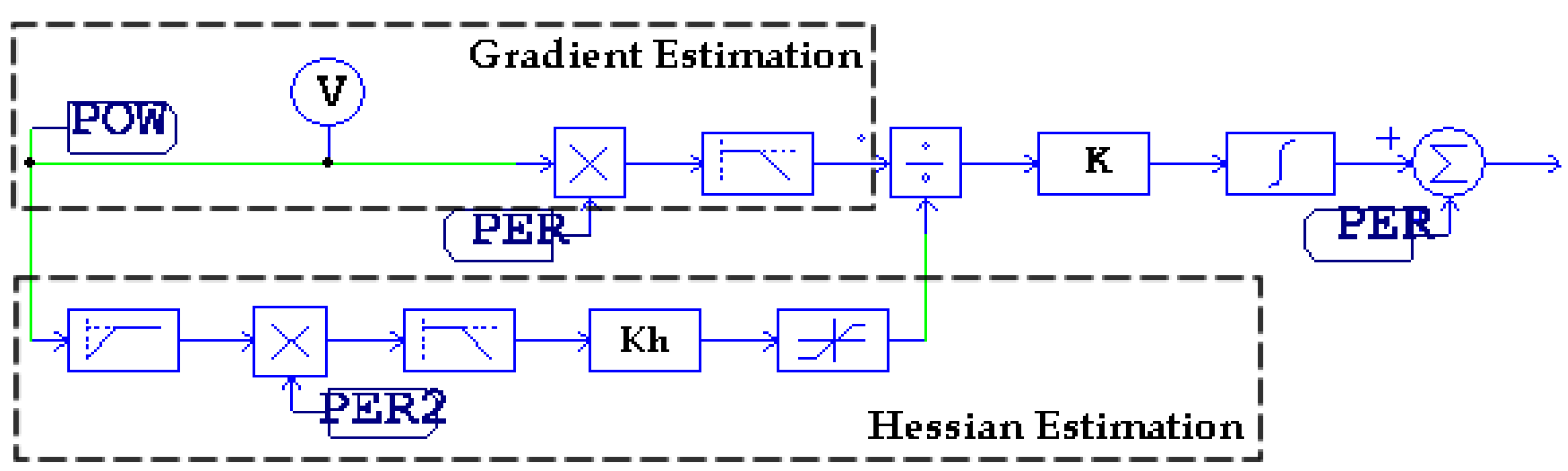
2. MPPT Based on NL-ESC Method

NL-ESC requires a Hessian estimation of voltage-power characteristic. Thus in this section, we describe, first, the Hessian estimation and then the rest of blocks of the proposed MPPT diagram.

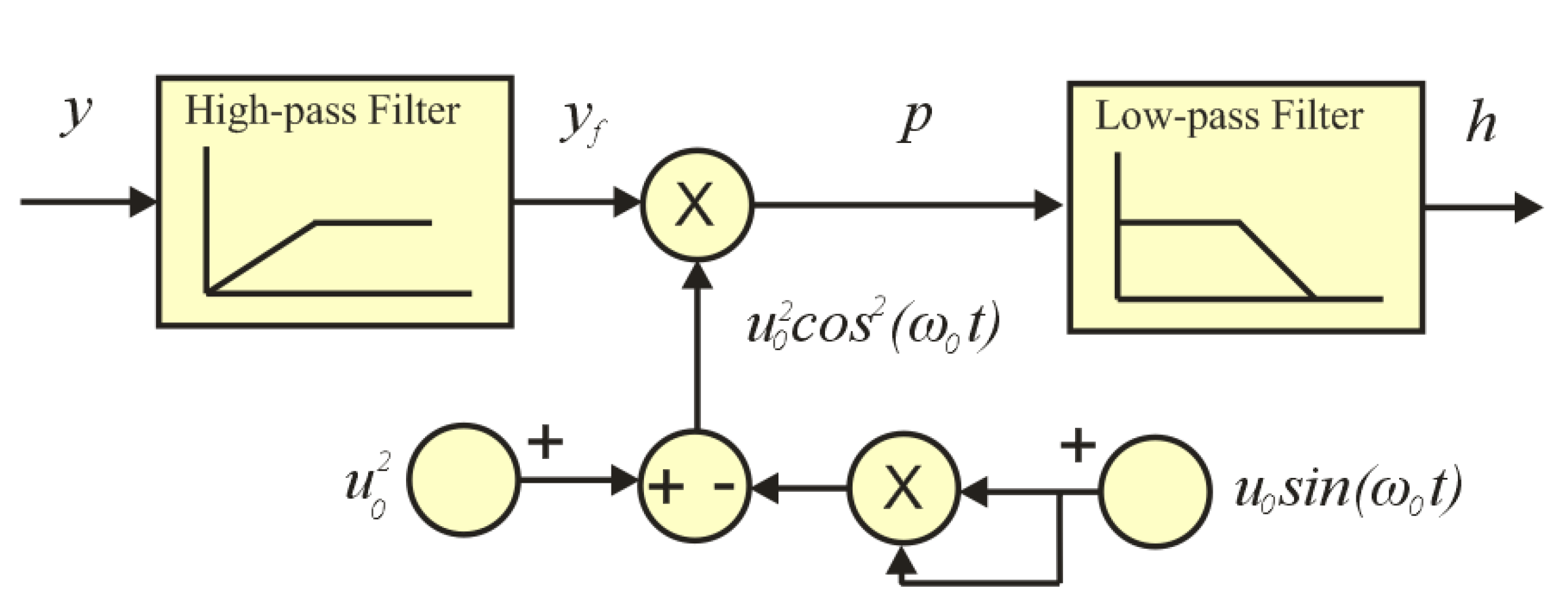
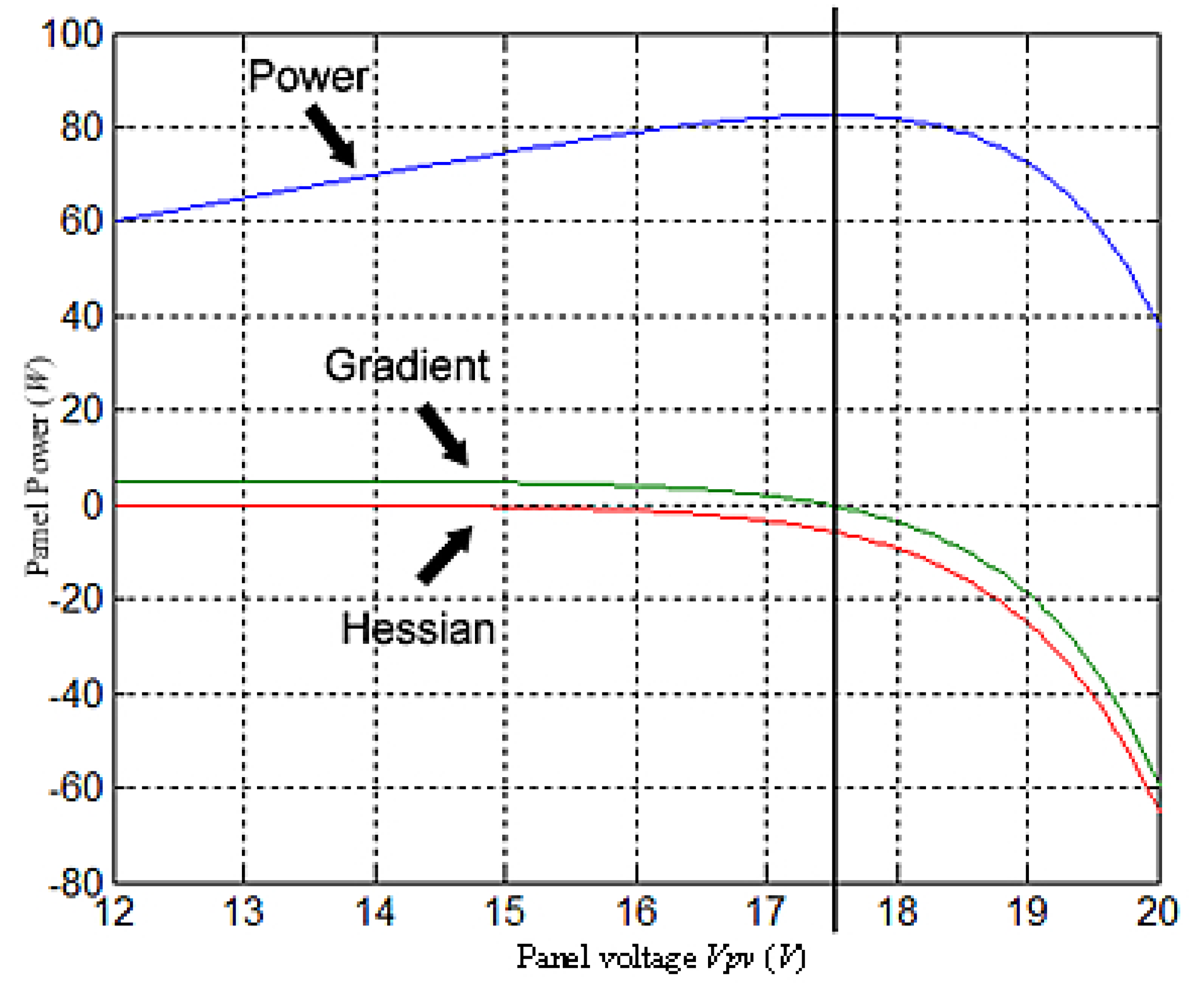
2.1. Hessian Estimation of the PV Panel Characteristic

Given a non-linear panel characteristic:
y = f ( x )
where y is the output power and x represents the generator input and considering that the input x consists of a slow signal u and a sinusoidal dithering of small amplitude u0 and angular frequency ω0; that is:
x = u + u 0 sin ( ω 0 t )
then the output power expression corresponds to:
y = f ( u + u 0 sin ( ω 0 t ) )
The power Equation (3) can be approximated by the first terms of Taylor series around a given value u:
y f ( u ) + d f ( u ) d u u 0 sin ( ω 0 t ) + 1 2 d 2 f ( u ) d u 2 u 0 2 sin 2 ( ω 0 t )
which, in turn, can be rewritten as:
y f ( u ) + d f ( u ) d u u 0 sin ( ω 0 t ) + 1 4 d 2 f ( u ) d u 2 u 0 2 1 4 d 2 f ( u ) d u 2 u 0 2 cos ( 2 ω 0 t )
It can be observed that the panel output is made up of a low frequency component, a first harmonic component at ω0 and a second harmonic component at 0. The information about the curvature or Hessian of the panel characteristic is associated with the second harmonic. Then, in order to extract this information, we apply a high-pass filter G(s) to the output power y, obtaining the following filtered output yf ; that is:
y f d f ( u ) d u u 0 sin ( ω 0 t ) 1 4 d 2 f ( u ) d u 2 u 0 2 cos ( 2 ω 0 t )
Then multiplying the filtered output by u02cos2(ω0t), we obtain:
p 1 2 d f ( u ) d u u 0 3 sin ( ω 0 t ) + 1 4 d f ( u ) d u u 0 3 sin ( 3 ω 0 t ) 1 4 d f ( u ) d u u 0 3 sin ( ω 0 t ) 1 8 d f 2 ( u ) d u 2 u 0 4 cos ( 2 ω 0 t ) 1 16 d f 2 ( u ) d u 2 u 0 4 1 16 d f 2 ( u ) d u 2 u 0 4 cos ( 4 ω 0 t )
It can be noted that, the Hessian information is associated with the continuous component of p. Consequently, we apply a low-pass filter, H(s), to obtain the estimation of the Hessian:
h 1 16 d f 2 ( u ) d u 2 u 0 4
In the sequel, we state as Hessian estimation the term h, which is a proportional magnitude of the real Hessian value with opposite sign. We should remark that the filtered output power is multiplied by the term u02cos2(ω0t), thus this term must be available. This term can be implemented from the dithering signal u0sin(ω0t) by means of a dc generator plus a four-quadrant analog multiplier, according to:
u 0 2 cos 2 ( ω t ) = u 0 2 u 0 2 sin 2 ( ω t )
Figure 4 shows the Hessian estimation schema that is used to implement the MPPT based on the NL-ESC method. In Figure 4, the high-pass filter, the low-pass filter, the multiplier element and the realization of the term u02cos2(ω0t) can be observed.
Figure 4. Hessian estimation schema.
Energies 05 02652 g004
The low-pass filter in the Hessian estimator corresponds to the second order transfer function:
H ( s ) = H 0 s 2 + 2 ξ H ω 0 H s + ω 0 H 2
and the high-pass filter corresponds to:
G ( s ) = G 0 s 2 s 2 + 2 ξ G ω 0 G s + ω 0 G 2
Filter parameters are illustrated in Table 1 of Section 3, where we show a specific implementation adapted to the BP-585 panel.

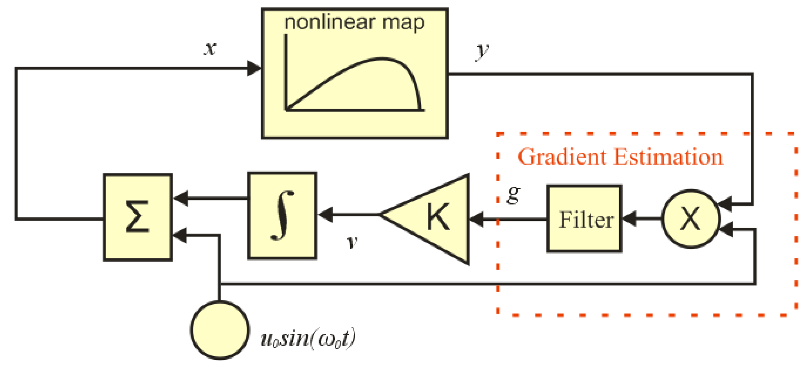
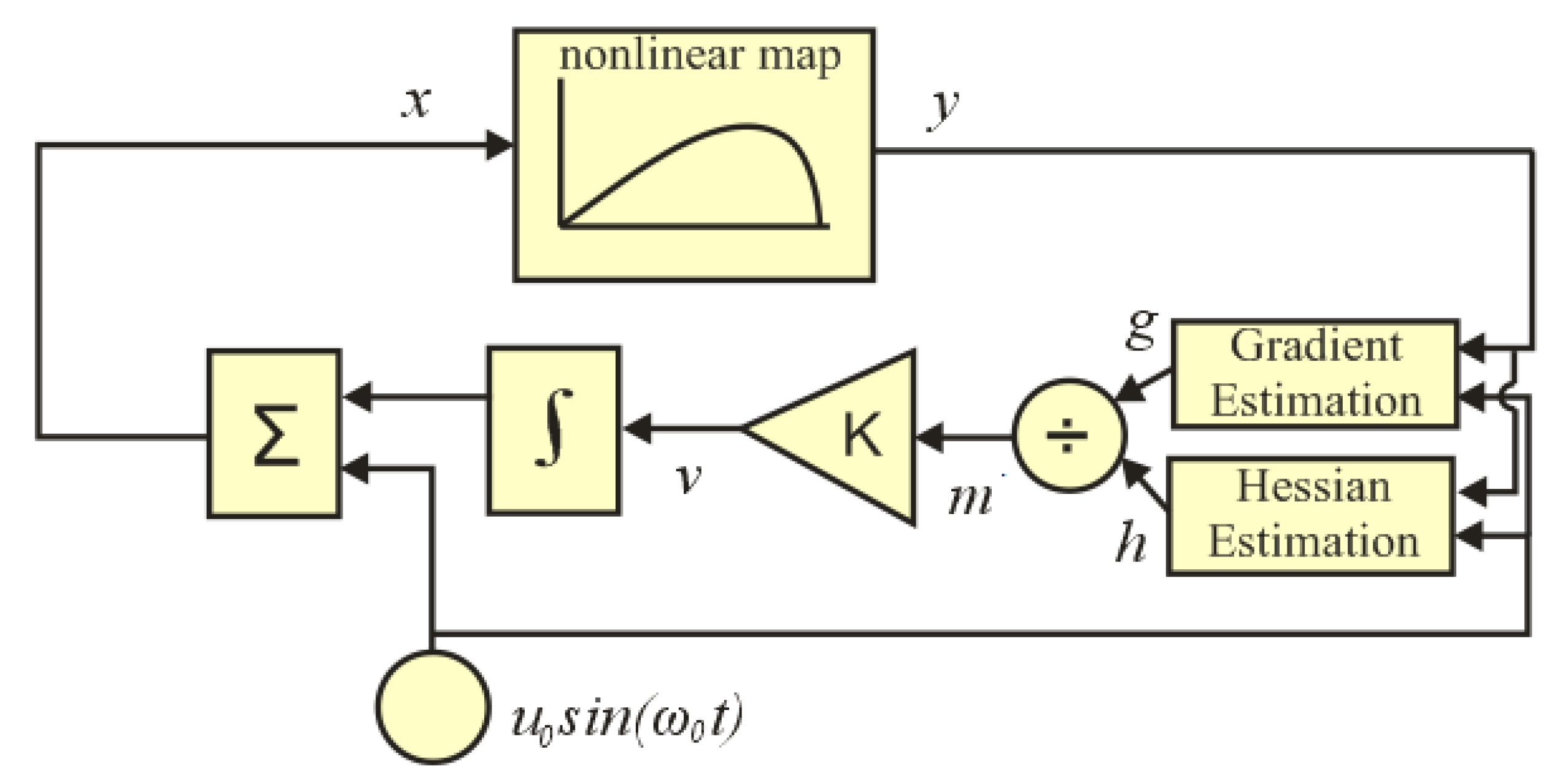
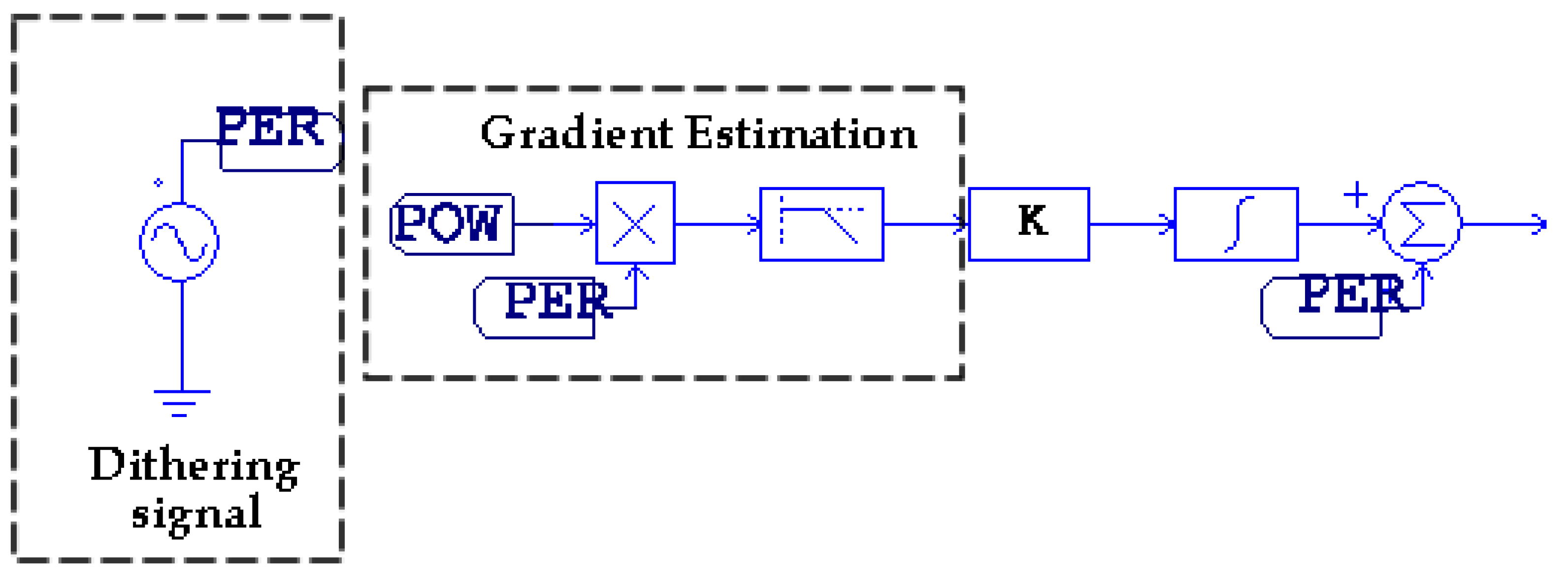
2.2. NL-ESC Method for MPPT in Photovoltaic Domain

The proposed MPPT based on NL-ESC method for PV purposes operates according to schema of Figure 3, where the input signal x corresponds to the converter duty-cycle. Given that the nonlinear map block represents the PV generator, which consists of a dc-dc converter and PV panel, and the converter and panel transients are much faster than those of the MPPT loop, the PV generator can be modeled by a static nonlinear map. The PV generator operating point depends on the input signal x; this signal is the output of an integrator block plus a sinusoidal dithering signal of small amplitude. The input signal x must increase if the PV generator operates at the left of the maximum and must decrease if x is greater than the optimal point x*.
We multiply the PV generator output y by the sinusoidal dithering signal u0sin(ω0t) and then filter it to estimate the gradient; as it can be observed in Figure 1.
It can be seen that MPPT circuits using NL-ESC, shown in Figure 3, are slightly more complex than MPPT circuits based on ESC corresponding to Figure 1. However, with the proposed approach, we overcome drawbacks due to large gains in the circuits when the gradient of the PV generator characteristics has a very large absolute value. We remark that the integrator input v is proportional to the gradient in MPPT circuits based on ESC [7], and proportional to the gradient divided by the Hessian in MPPT circuits based on NL-ESC [10].
In a practical implementation, we add some saturation blocks after the Hessian estimation sub-circuit, to prevent a very low value of the divisor. Figure 5 depicts a PSIM schematic showing a detail of the gradient and the Hessian circuit implementation; also the placement of the saturation block with bounds V s a t l o w and V s a t h i g h can be observed. It should be noted that the Hessian value is almost zero when the operating point x is on the left-side of the optimum. This can be seen in Figure 6, which depicts the gradient and Hessian of the characteristic power versus input voltage in an 85 W PV panel.
Figure 5. PSIM Schematic of MPPT circuit based on NL-ESC.
Energies 05 02652 g005
Thus, we must remark that when the MPPT circuit based on NL-ESC operates on the left-side of the optimum, it behaves as an MPPT based on ESC since the Hessian term is saturated by V s a t l o w and, therefore, the variation of the PV operating point depends only on the gradient. Consequently, the approximation rate to its maximum depends on the curvature of the characteristic [11], that it is small and approximately constant. On the other hand, on the right-side of the maximum, the approximation rate to the maximum does not depend on the curvature, since the increasing term v is divided by the Hessian, thus avoiding large values of the increasing term that may cause instabilities in the MPPT circuit.
Figure 6. Voltage-power characteristic of a panel BP585F.
Energies 05 02652 g006

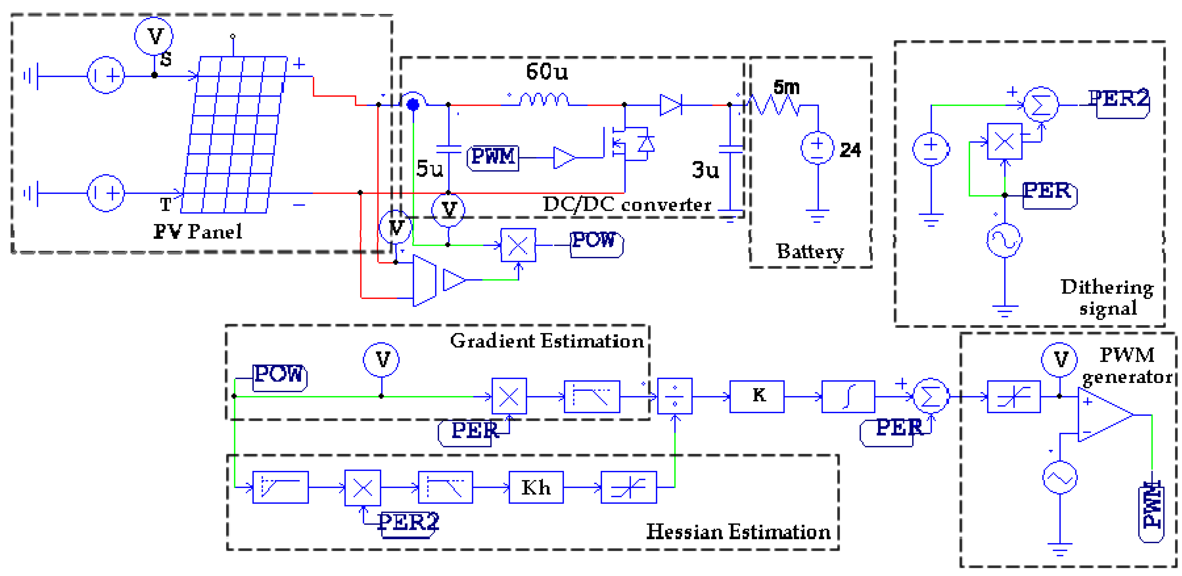
3. Comparison of ESC and NL-ESC MPPT by Means of PSIM Simulation

We compare the transient behavior of both MPPTs for a PV panel model BP585F. The nominal peak power is 85 W and the nominal optimal input voltage is 17.6 V. Table 1 shows the parameters of MPPT based on NL-ESC; specifically, the values of the dithering amplitude u0 and frequency ω0, the filter parameters for H(s) and G(s), and gain constant K. Table 2 shows the parameters of the MPPT based on ESC.
Table 1. Parameters of the MPPT based on NL-ESC.
u0H(s)KhK
H0ξHω0H
0.01 V1110π rad/s3,0000.2
Ω0G(s)Sat.bounds
G0ξGω0G V s a t l o w V s a t h i g h
50 Hz1160π rad/s0.0010.2
Table 2. Parameters of the MPPT based on ESC.
u0H(s)ω0K
H0ξHω0H
0.01 V1110π rad/s50 Hz200
Figure 7 shows the PSIM schematic that consists of a PV panel, a boost DC-DC converter; a battery and the blocks of the MPPT based on NL-ESC. It can be remarked that the DC-DC converter is operated at constant switching frequency by means of a PWM circuit. The battery model takes into account the parasitic internal resistance. We have used a built-in element of PSIM v9 whose parameters are shown in Table 3 as the PV panel model.
In the comparison of both MPPT approaches, we choose a loop gain constant K equal to 200 in the ESC case, while the loop gain constant K N L is inside the interval [1,200] in the NL-ESC case. Note that the relationship between these constants corresponds to K N L = K / K h , where K h is the gain of Hessian estimation block as shown in Figure 7.
Figure 7. PSIM schematic of the solar system in NL-ESC case.
Energies 05 02652 g007
Table 3. Parameters of the PV panel.
Numbers of cells (Ns)30Saturation Current (Is0)1.46 e−11
Standard Light Intensity (S0)1,000Band Energy (Eg)1.12
Reference Temperature (Tref)25Ideality Factor (a)1
Series Resistance (Rs)0.005Temperature Coefficient (Ct)0.0024
Shunt Resistance (Rsh)200kCoefficient Ks0
Short Circuit Current (Isc0)5
Blocks corresponding to the MPPT based on ESC are shown in Figure 8. We omit in the Figure the PV panel and DC-DC converter blocks that are the same than those in the NL-ESC approach.
Figure 8. PSIM schematic of MPPT in ESC case.
Energies 05 02652 g008
The following subsections show the transient behavior when the panel input voltage is on the left side of the optimal voltage and when it is at the right side. We have taken voltages far away from the optimum, corresponding to a boost-converter duty cycle Di = 0.8 (which is equivalent to 4.8 V in the panel) and Di = 0.15 (equivalent to 20.4 V in the panel).

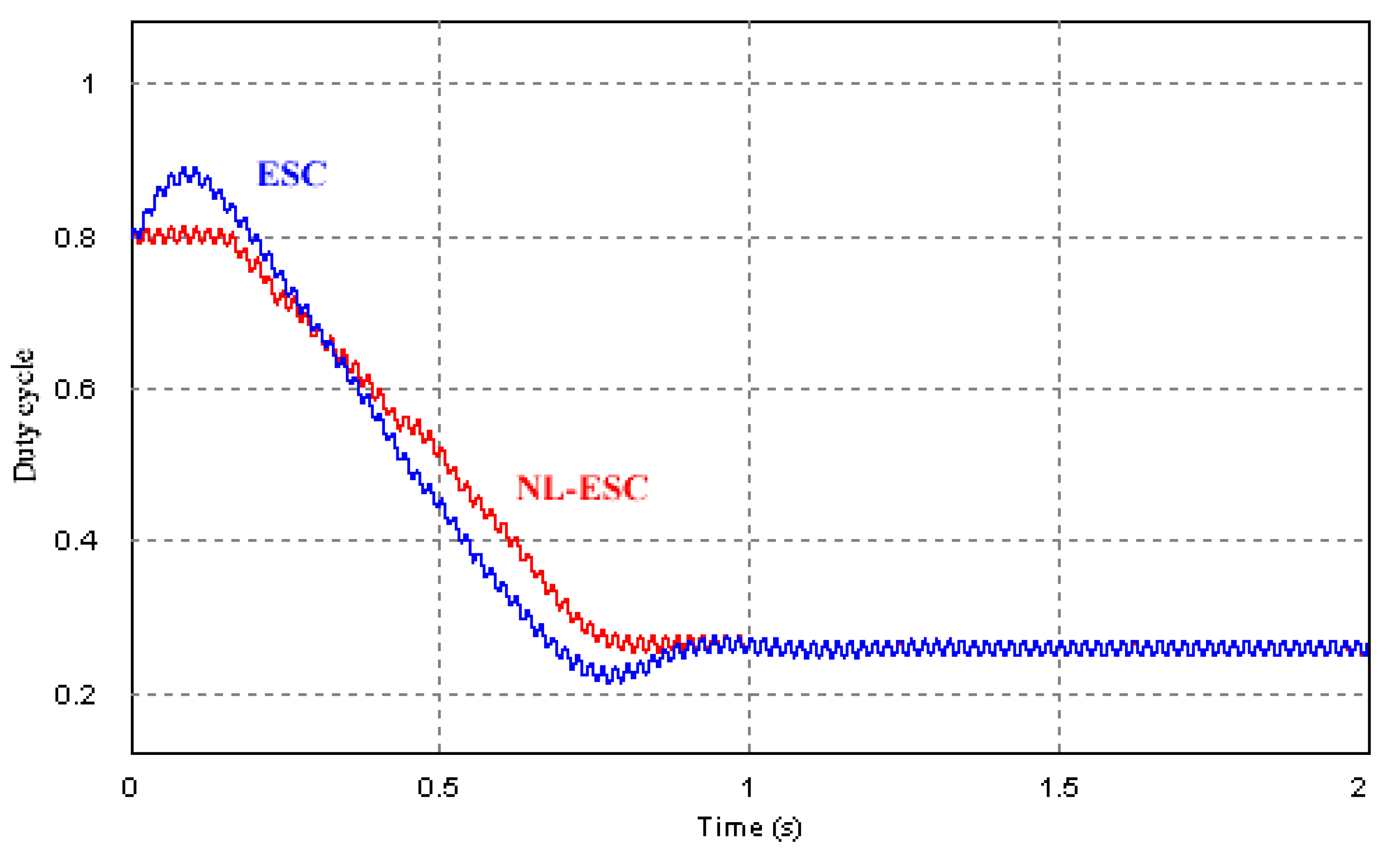
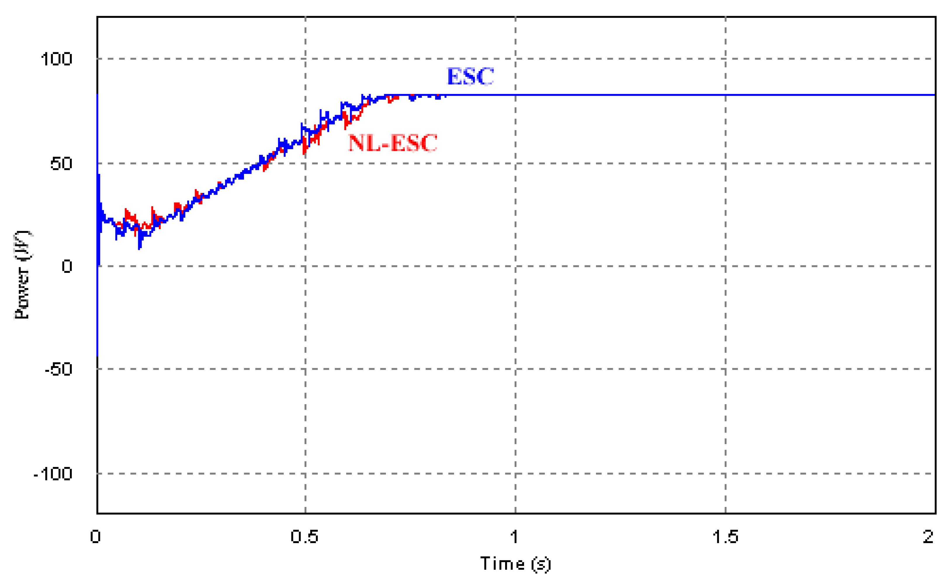
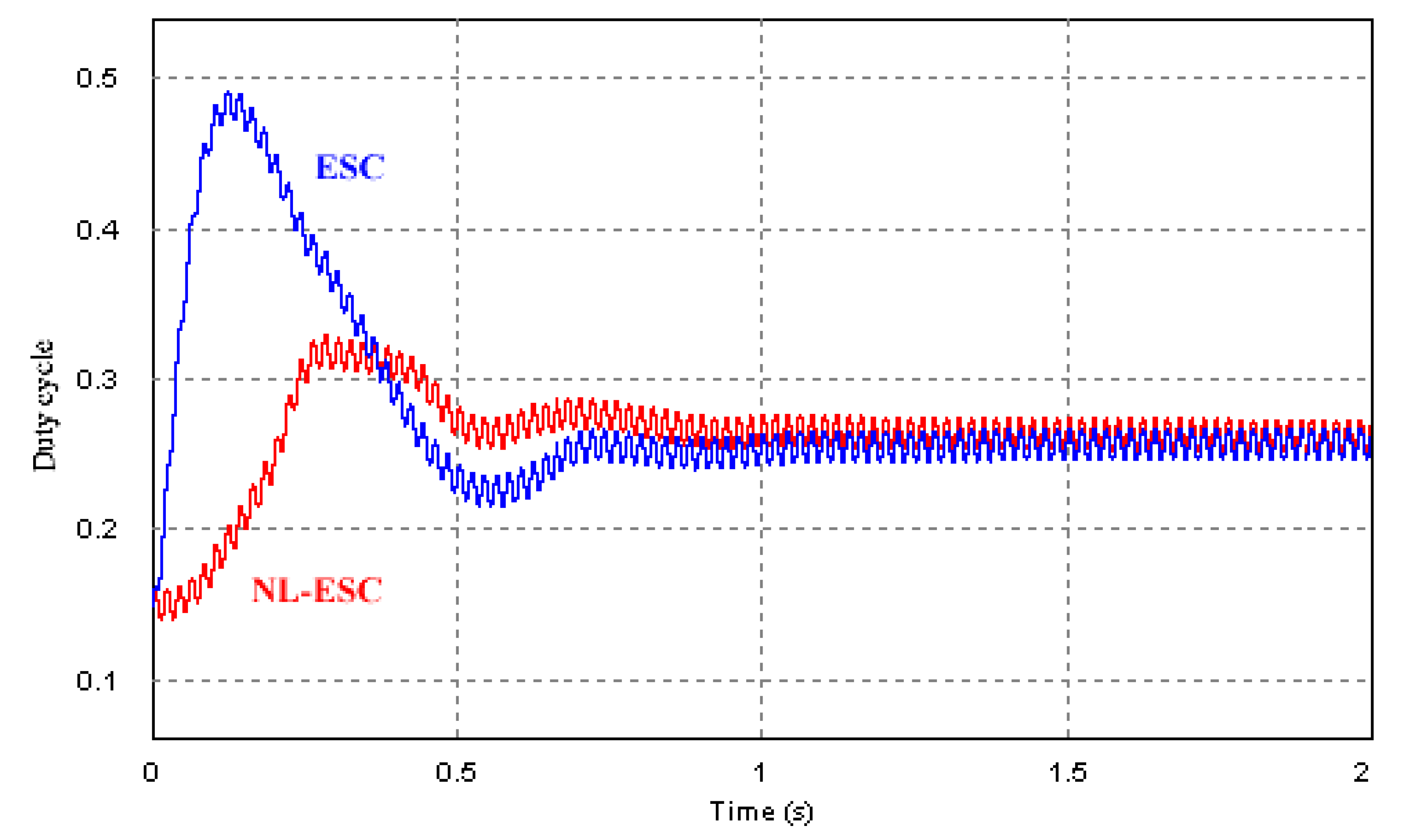
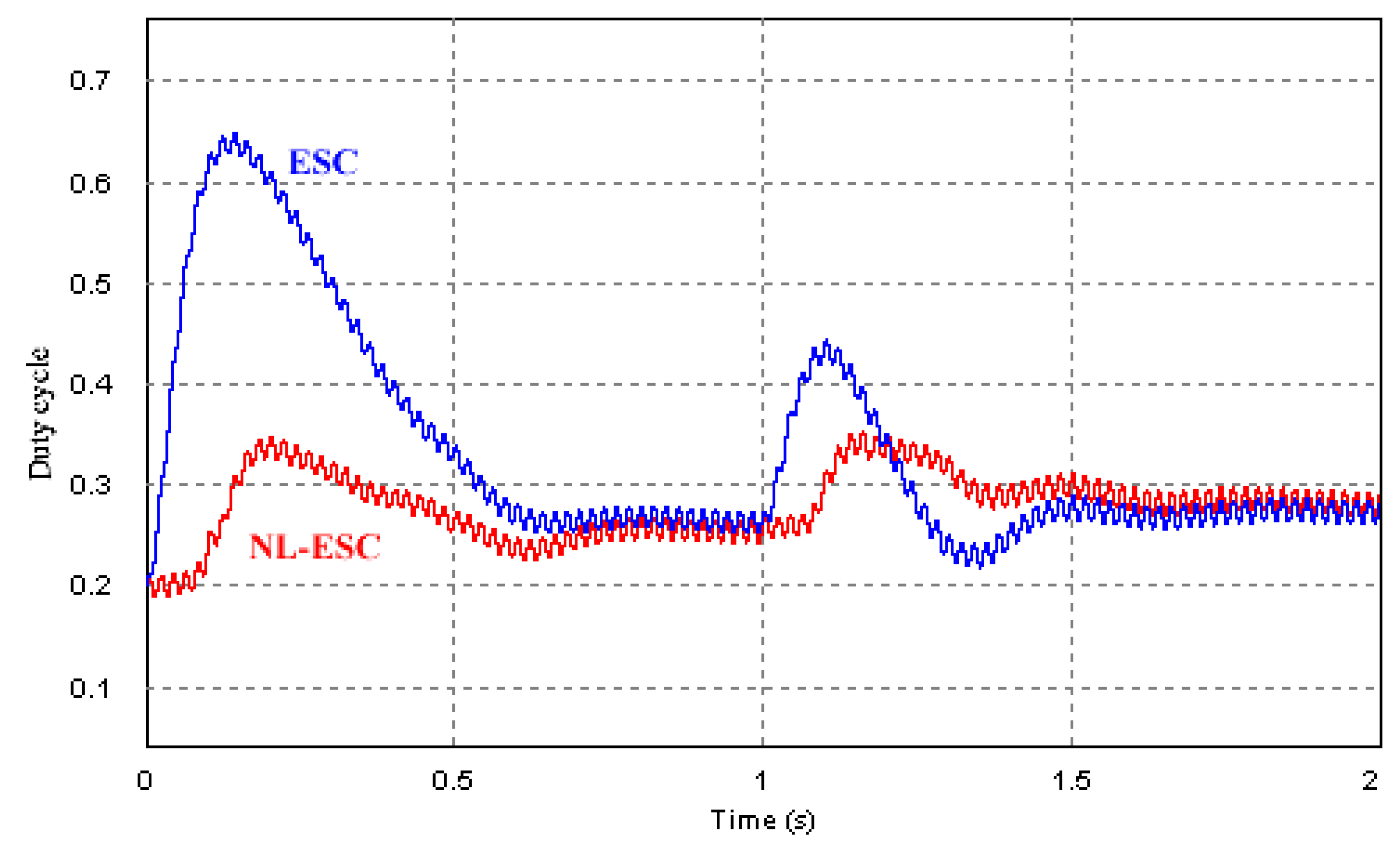
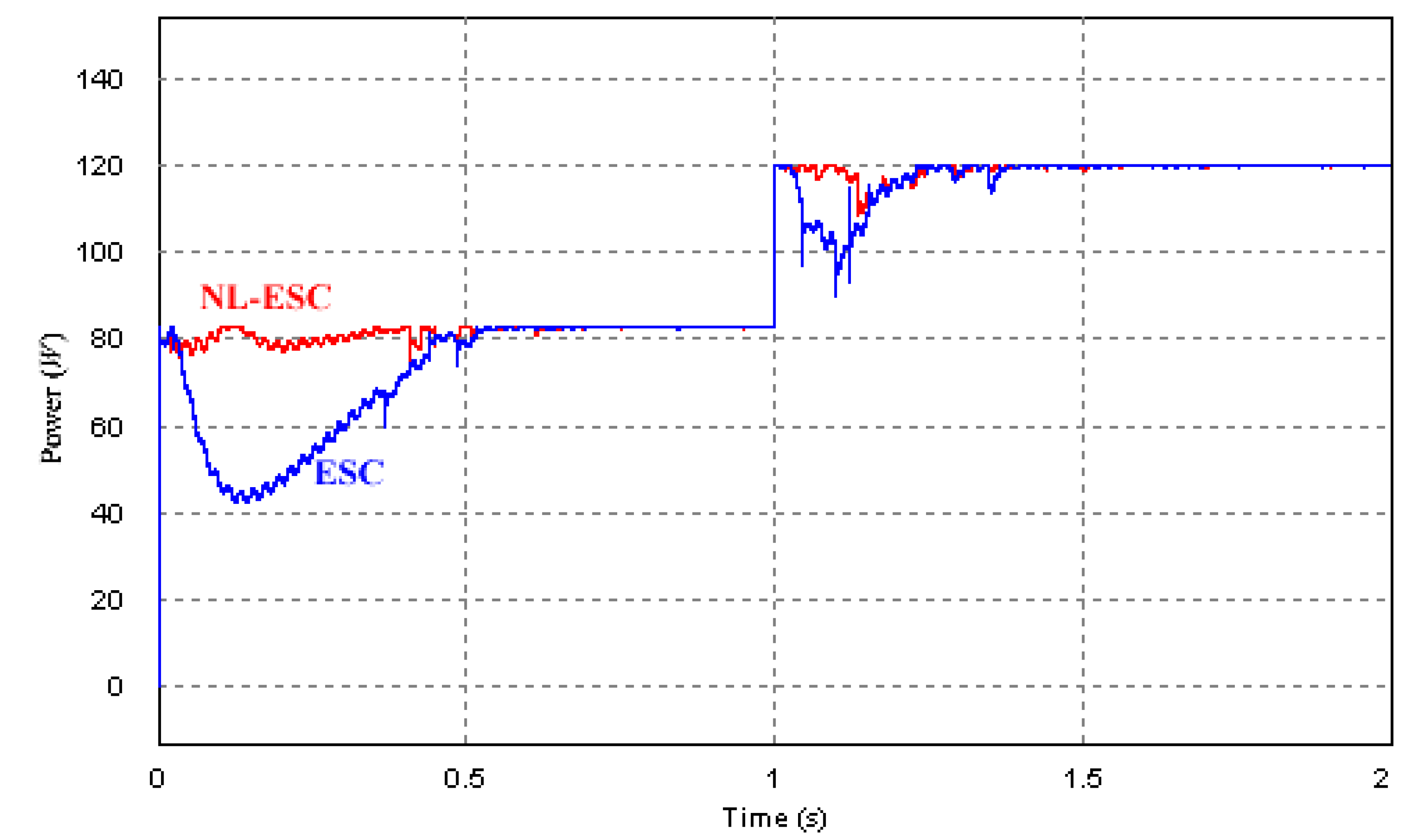
3.1. Transient Waveform Starting at Di = 0.8

The Hessian value almost zero when the panel voltage is low, as depicted in Figure 6, then the Hessian term is, according to Figure 5, saturated to V s a t l o w . This is why both MPPTs waveforms are very similar. Waveforms corresponding to the duty-cycle transient and panel power transient are shown in Figure 9 and Figure 10, respectively. Nonetheless, a little difference may be noticed when the voltage is near to the optimum and the Hessian term is bigger than the saturation low limit V s a t l o w .

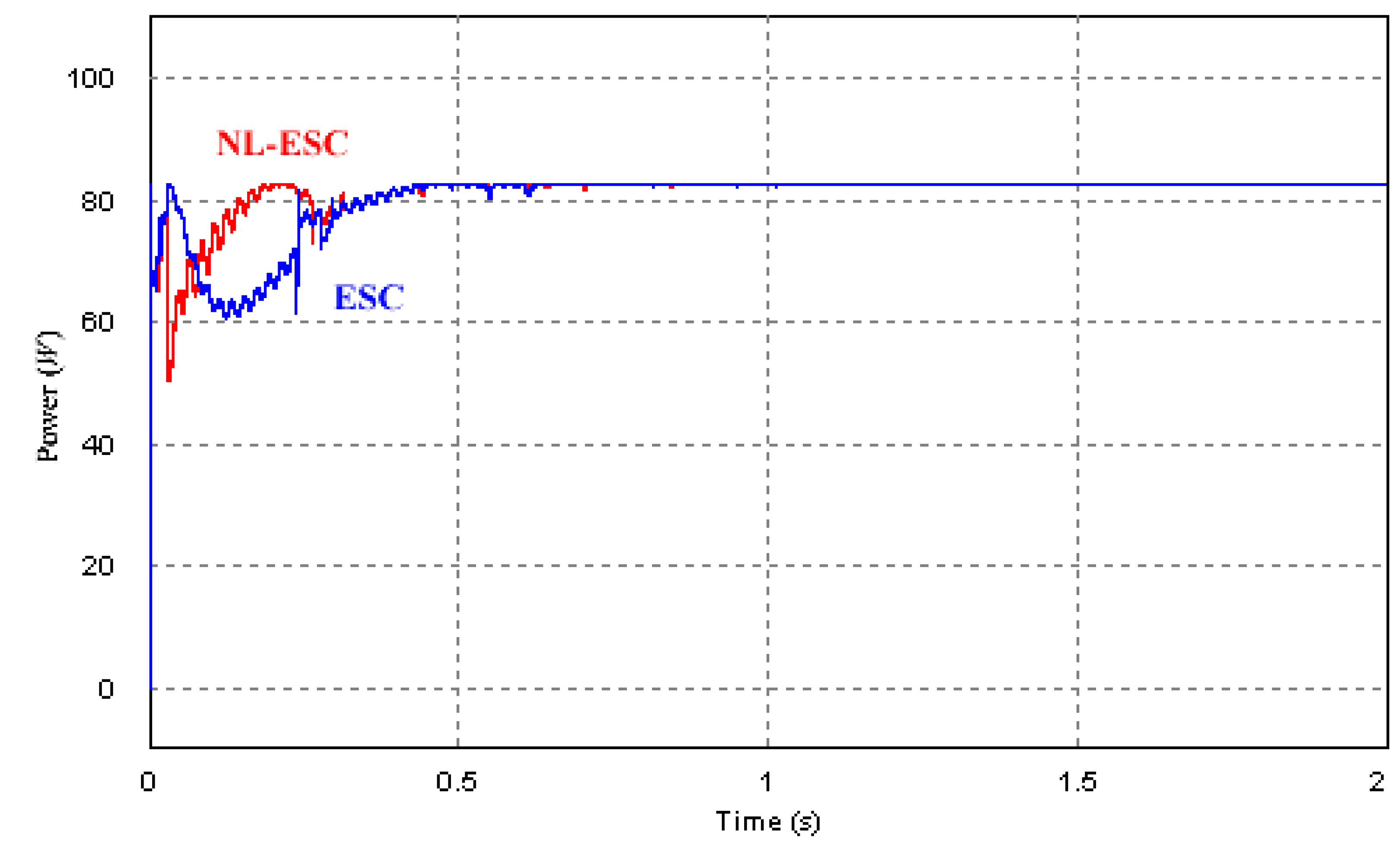
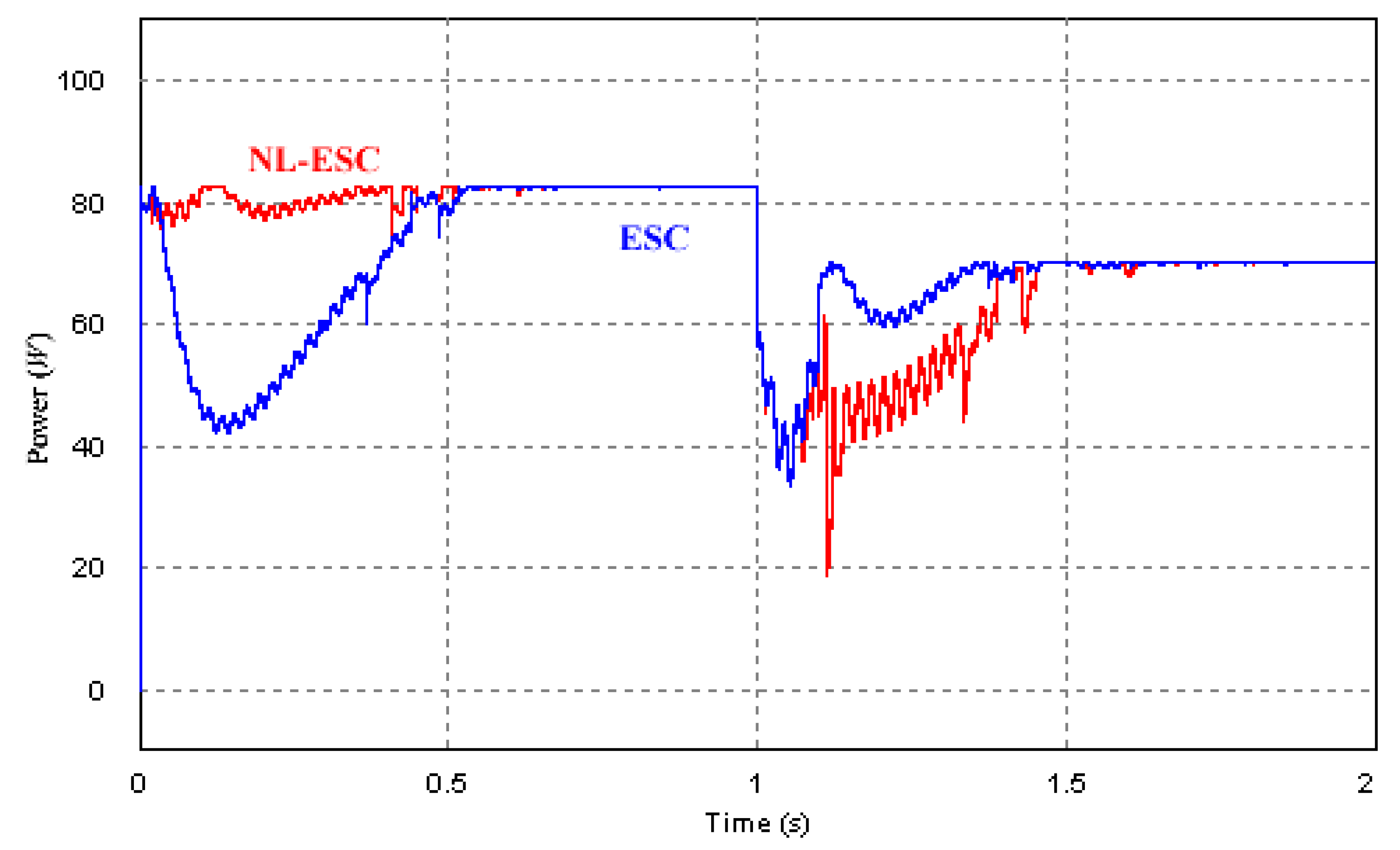
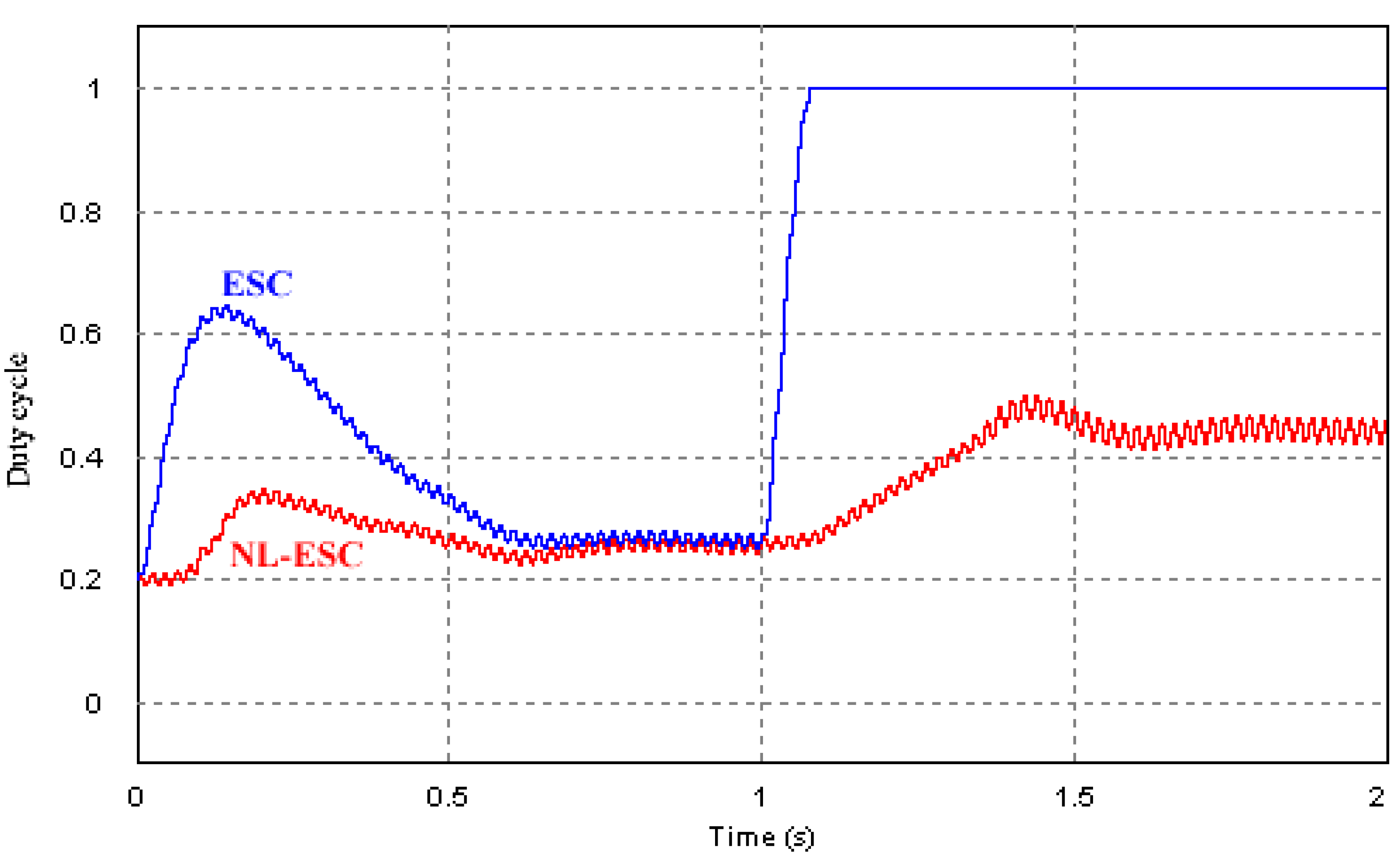
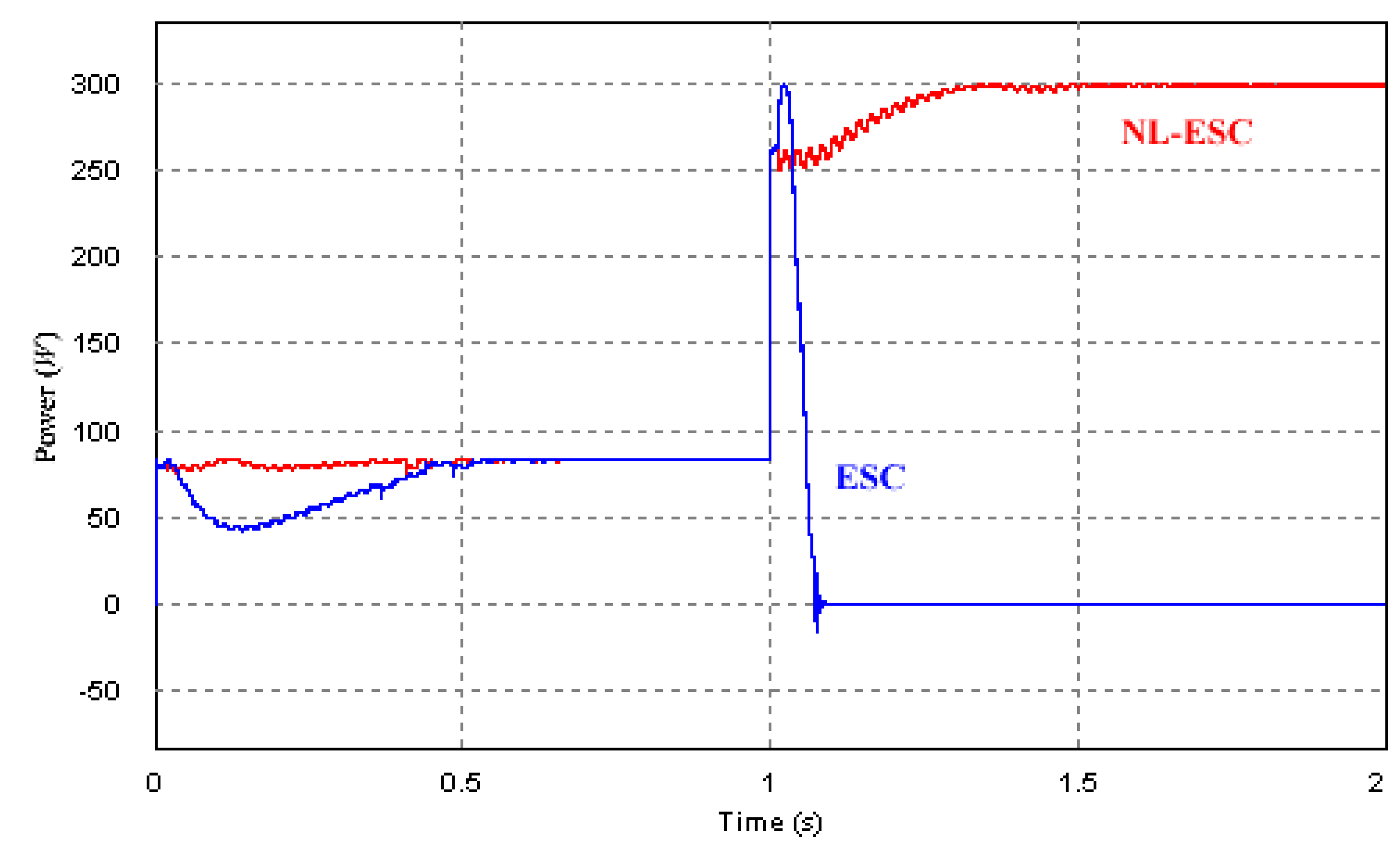
3.2. Transient Waveform Starting at Di = 0.15

A low starting value of the duty-cycle in the boost converter implies a high voltage in the panel port. This means, according to Figure 6, that the Hessian is not small in absolute value terms and consequently the Hessian term is not saturated in the NL-ESC case. The loop gain constant K N L will move inside the interval [1,200], and the transient behavior will be different to that of the ESC where the loop gain constant K is 200. Figure 11 and Figure 12 show the transient waveform of duty-cycle and output power, respectively, for both MPPT approaches when the starting duty-cycle is Di = 0.15.
We can choose an adequate value of loop-gain constant K for the MPPT based on ESC for a given starting point and some given weather conditions. Nevertheless, when the starting point or weather conditions change, this value may be too big and therefore the system will become unstable or too small and the transient will be very slow. On the contrary, the equivalent loop-gain constant K N L does not depend on either the starting point or the weather condition and therefore we overcome these drawbacks. We illustrate these different behaviors in the following subsection.
Figure 9. Transient of duty-cycle starting at Di = 0.8 in NL-ESC case (Red); Transient of duty-cycle starting at Di = 0.8 in ESC case (Blue).
Energies 05 02652 g009
Figure 10. Transient of output power from Di = 0.8 in NL-ESC case (Red); Transient of output power from Di = 0.8 in ESC case (Blue).
Energies 05 02652 g010
Figure 11. Transient of duty-cycle from Di = 0.15 in NL-ESC case (Red); Transient of duty-cycle from Di = 0.15 in ESC case (Blue).
Energies 05 02652 g011
Figure 12. Transient of panel power from Di = 0.15 in NL-ESC case (Red); Transient of panel power from Di = 0.15in ESC case (Blue).
Energies 05 02652 g012

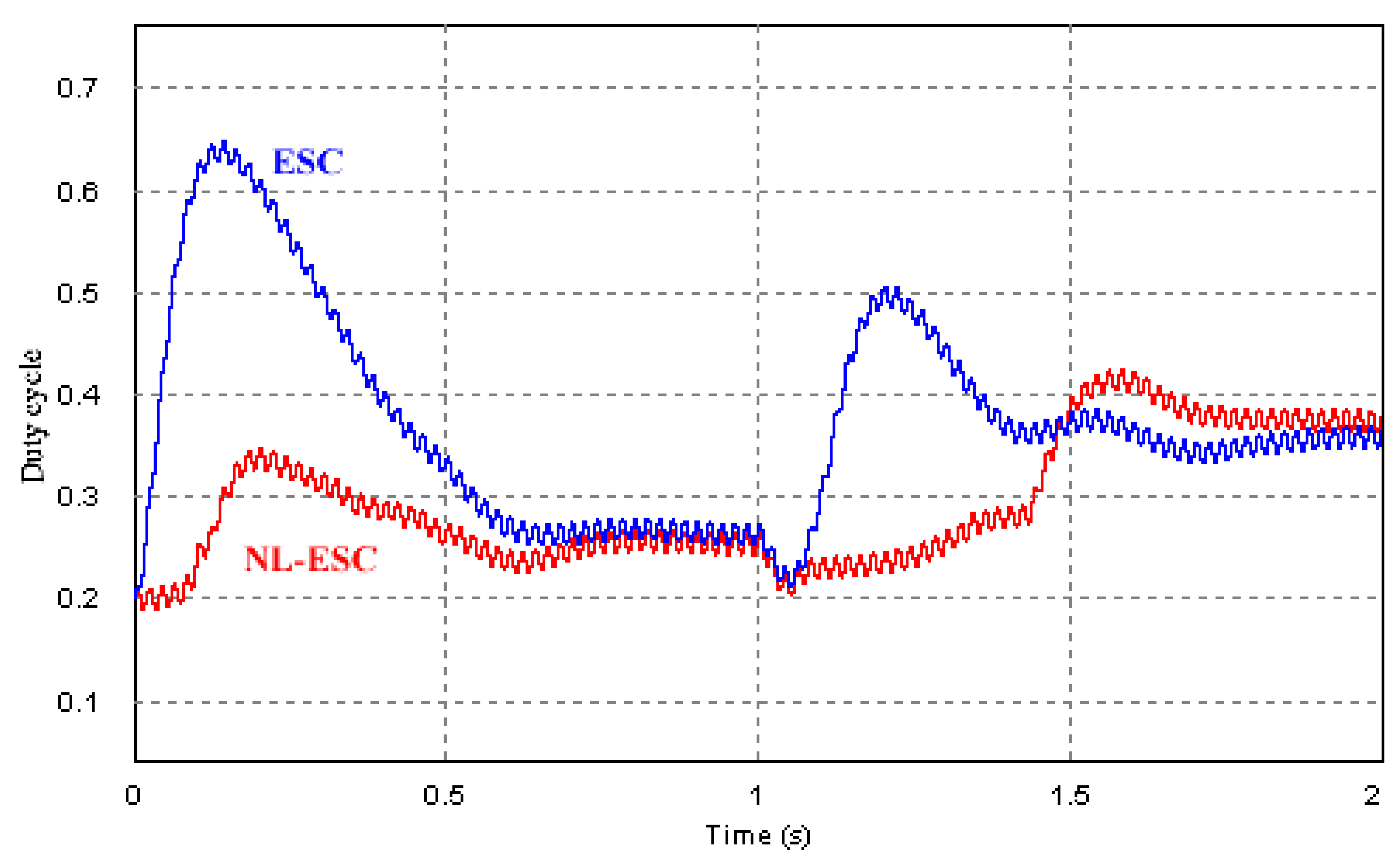
3.3. Response of MPPT Approaches in Front of Weather Conditions Change

We compare the response of both MPPTs to changes of temperature and irradiation, specifically to an abrupt temperature change from 25 °C to 50 °C at t = 1 s. A fast temperature change will involve a fast change of the optimal panel voltage, and the MPPT circuits should react in a fast and reliable manner. Although fast temperature changes are not usual, this analysis, by means of simulations, allows us to evaluate the robustness of the MPPT algorithm, and it can be tested by the connection and disconnection of panels in series. Figure 13 and Figure 14 depict MPPT waveforms when an abrupt change of temperature occurs; both MPPTs reach the optimal point, but nevertheless the transient is different.
Figure 13. Transient of the duty-cycle in front an abrupt change of temperature in NL-ESC case (Red) and in ESC case (Blue).
Energies 05 02652 g013
Figure 14. Transient of panel power in front an abrupt change of temperature in NL-ESC case (Red) and in ESC case (Blue).
Energies 05 02652 g014
Irradiance changes occur very often in terrestrial PV systems; this is why MPPT circuits should react in a fast and reliable manner. When irradiance changes, the optimum voltage shifts slightly; however the power output change in a great extent and, as a consequence, the MPPT signal also changes abruptly even when the MPPT operating point is near to the optimum. We note in Figure 15 and Figure 16 that both MPPT approaches react in a correct way to abrupt change of irradiance. We also see that the transient responses are different.
Figure 15. Transient of duty-cycle in front an abrupt irradiance decrease in NL-ESC case (Red) and in ESC case (Blue).
Energies 05 02652 g015
Figure 16. Transient of panel power in front an abrupt irradiance decrease in NL-ESC case (Red) and in ESC case (Blue).
Energies 05 02652 g016
Nevertheless, an abrupt increase in irradiance may cause unstable behavior. This is because during the transient the panel voltage exceeds the open-voltage value and the MPPT is not able to obtain the gradient of the panel characteristic since the power is zero. Due to the fact that the equivalent loop-gain is adapted in the NL-ESC approach, the NL-ESC waveforms have less overshoot and then this approach is more stable, as Figure 17 and Figure 18 corroborate.
Figure 17. Transient of duty-cycle in front an abrupt irradiance increase in NL-ESC case (Red) and in ESC case (Blue).
Energies 05 02652 g017
Figure 18. Transient of panel power in front an abrupt irradiance increase in NL-ESC case (Red) and in ESC case (Blue).
Energies 05 02652 g018
Figure 15 and Figure 16, which depict the response to an irradiance change from 1000 W/m2 to 1500 W/m2 at t = 1 s, show that the optimal panel voltage changes slightly, and they also show a stable behavior. On the contrary, Figure 17 and Figure 18 which correspond to the response to an irradiance change from 1000 W/m2 to 6000 W/m2 at t = 1 s, depict a small change in the optimal panel voltage (or the equivalent duty-cycle) in the NL-ESC approach and also illustrate that the ESC approach becomes unstable. These simulations show that an approach that takes into account the Hessian or curvature of the panel power is more reliable.
Performances of MPPTs are, in most cases, bounded by noise generated by their subcircuits [14,15]. The noise affects performances of the MPPT based on ESC as well as based on other approaches. We show the MPPT behavior in the presence of noise by means of a simulation where we add to the power signal a square signal with the same frequency of that of the converter switching frequency and amplitude equal to 0.3 W. The added noise is much greater than ripple noise in the converter and despite the fact that this approach estimates two magnitudes; namely, the gradient and the Hessian, the results do not show any appreciable change.

4. Conclusions

The article reviews the technique named Newton-like Extremum Seeking Control and adapts it as MPPT circuit for photovoltaic systems. This technique uses the Hessian or curvature of the panel power to seek the maximum point. We describe the functional blocks of the proposed MPPT. Also, the paper compares this MPPT approach with an approach based on common Extremum Seeking Control. The MPPT circuits based on both approaches have been simulated with PSIM. We corroborate the different transient behavior. Simulation waveforms verify that the MPPT based on Newton-like Extremum Seeking Control is more stable. Proposals to extend the method to parallel and serial connected panels are being studied.

Acknowledgments

This work was supported by the Spanish Ministerio de Ciencia e Inovación under grant DPI2010-16481.

References

  1. Esram, T.; Chapman, P.L. Comparasion of photovoltaic array Maximum Power Point Tracking techniques. IEEE Trans. Energy Convers. 2007, 22, 439–449. [Google Scholar] [CrossRef]
  2. Yau, H.T.; Wu, C.H. Comparison of Extremum-Seeking Control techniques for Maximum Power Point Tracking in photovoltaic systems. Energies 2011, 4, 2180–2195. [Google Scholar] [CrossRef]
  3. Leyva, R.; Alonso, C.; Queinnec, I.; Cid-Pastor, A.; Lagrange, D.; Martinez-Salamero, L. MPPT of photovoltaic systems using Extremum Seeking Control. IEEE Trans. Aerosp. Electron. Syst. 2006, 42, 249–258. [Google Scholar] [CrossRef]
  4. Olalla, C.; Arteaga, M.I.; Leyva, R.; El Aroudi, A. Analysis and comparison of Extremum Seeking Control techniques. In Proceedings of the 2007 IEEE International Symposium on Industrial Electronics (ISIE 2007), Vigo, Spain, 4–7 June 2007; pp. 72–76.
  5. Brunton, S.L.; Rowley, C.W.; Kulkarni, S.R.; Clarkson, C. Maximum Power Point Tracking for photovoltaic optimization using ripple-based Extremum Seeking Control. IEEE Trans. Power Electron. 2010, 25, 2531–2540. [Google Scholar] [CrossRef]
  6. Bazzi, A.M.; Krein, P.T. Concerning “Maximum Power Point Tracking for photovoltaic optimization using ripple-based Extremum Seeking Control”. IEEE Trans. Power Electron. 2011, 26, 1611–1612. [Google Scholar] [CrossRef]
  7. Leyva, R.; Olalla Martinez, C.; Zazo, H.; Cabal, C.; Cid Pastor, A.; Queinnec, I.; Alonso, C. MPPT based on Sinusoidal Extremum Seeking Control in PV generation. Int. J. Photoenergy 2012, 2012, 672765:1–672765:7. [Google Scholar] [CrossRef]
  8. Jeong, H.G.; Seung, R.H.; Lee, K.B. An improved Maximum Power Point Tracking method for wind power systems. Energies 2012, 5, 1339–1354. [Google Scholar] [CrossRef]
  9. Zhu, Y.; Cheng, M.; Hua, W.; Wang, W. A novel Maximum Power Point Tracking control for permanent magnet direct drive wind energy conversion systems. Energies 2012, 5, 1398–1412. [Google Scholar] [CrossRef]
  10. Moase, W.H.; Manzie, C.; Brear, M.J. Newton-like extremum-seeking for the control of thermoacoustic instability. IEEE Trans. Autom. Control 2010, 55, 2094–2105. [Google Scholar] [CrossRef]
  11. Leyva, R.; Artillan, P.; Cabal, C.; Estibals, B.; Alonso, C. Dynamic performance of Maximum Power Point Tracking circuits using Sinusoidal Extremum Seeking Control for photovoltaic generation. Int. J. Electron. 2011, 94, 529–542. [Google Scholar] [CrossRef]
  12. Morosanov, I.S. Methods of Extremum Seeking Control. Autom. Remote Control 1957, 18, 1077–1092. [Google Scholar]
  13. Ariyur, K.B.; Krstic, M. Real-Time Optimization by Extremum-Seeking Control; Wiley-Interscience: New York, NY, USA, 2003. [Google Scholar]
  14. Latham, A.M.; Sullivan, C.R. Optimization of a continuous-time Maximum Power Point Tracking algorithm in the presence of noise. In Proceedings of the 12th IEEE Workshop on Control and Modeling for Power Electronics (COMPEL 2010), Boulder, CO, USA, 28–30 June 2010; pp. 1–7.
  15. Al-Atrash, H.; Batarseh, I.; Rustom, K. Effect of measurement noise and bias on Hill-Climbing MPPT Algorithms. IEEE Trans. Aerosp. Electron. Syst. 2010, 46, 745–760. [Google Scholar] [CrossRef]

