Article

Energy and Exergy Analysis and Optimization of Combined Heat and Power Systems. Comparison of Various Systems

1
Laboratoire d’Energétique et de Mécanique Théorique et Appliquée (LEMTA), Lorraine University, UMR CNRS 7563, 2 Avenue de la Forêt de Haye, 54516 Vandoeuvre-Les-Nancy Cedex, France
2
Department of Engineering Thermodynamics, Engines, Thermal and Refrigerating Equipment, University “Politehnica” of Bucharest, Splaiul Independentei 313, 060042 Bucharest, Romania
*
Author to whom correspondence should be addressed.
Energies 2012, 5(9), 3701-3722; https://doi.org/10.3390/en5093701
Submission received: 14 July 2012 / Revised: 3 September 2012 / Accepted: 19 September 2012 / Published: 24 September 2012
(This article belongs to the Special Issue Exergy Analysis of Energy Systems)

Abstract

:
The paper presents a comparison of various CHP system configurations, such as Vapour Turbine, Gas Turbine, Internal Combustion Engine, External Combustion Engine (Stirling, Ericsson), when different thermodynamic criteria are considered, namely the first law efficiency and exergy efficiency. Thermodynamic optimization of these systems is performed intending to maximize the exergy, when various practical related constraints (imposed mechanical useful energy, imposed heat demand, imposed heat to power ratio) or main physical limitations (limited heat availability, maximum system temperature allowed, thermo-mechanical constraints) are taken into account. A sensitivity analysis to model parameters is given. The results have shown that the various added constraints were useful for the design allowing to precise the influence of the model main parameters on the system design. Future perspective of the work and recommendations are stated.

1. Introduction

A cogeneration plant, also called a CHP system (Combined Heat and Power Production), can operate at efficiencies greater than those achieved when heat and power are produced in separate or distinct processes. For example, efficiency values go from 35%–40% for electrical or mechanical production, to 80%–85% for the cogeneration system efficiency [1]. The environmental issue should be also considered as an important cogeneration system advantage with respect to carbon dioxide emissions, which are mainly responsible for the greenhouse effect.
In the recent past, due to environmental impact considerations and energy efficient use purposes, a renewal and development of combined heat and power systems was increasing from large to small scale CHP systems, even μCHP, and for industrial or building applications [1,2,3,4,5,6,7,8,9,10,11,12,13,14]. New configurations of CHP systems were studied and among them photovoltaic/thermal (PV/T) configurations [15,16,17] or fuel cell CHP systems [2,4,14] are close to implementation in the near future. Also the fuel disposal issue was considered, mainly by various biomass availabilities [16,18,19], or gasoline and hydrogen [10]. Analysis of the CO2 mitigation costs of large-scale biomass-fired cogeneration technologies with CO2 capture and storage was performed [19], showing that biomass-fired cogeneration plants based on integrated gasification combined cycle technology (CHP-BIGCC) is very energy and emission efficient and also cost competitive compared with other conversion systems. A new analytical approach based on the current models of the solid oxide fuel cell and gas turbine was elaborated [20], in which multiple irreversibilities existing in real hybrid systems are taken into account. The general performance characteristics of the hybrid system (irreversible solid oxide fuel cell-gas turbine) were revealed and the optimum criteria of the main performance parameters were determined. Other hybrid systems were considered [21], such as bi-energy technologies (gas and electricity), as a path to transfer loads from one system to another, so an absolute peak load reduction by 17% at the small scale was found. A novel conceptualisation considering the steam cycle of a combined heat and power generator thermodynamically equivalent to a conventional steam cycle generator plus an additional virtual steam cycle heat pump [22] leads to the conclusion that the performance of CHP will tend to be significantly higher than that of real heat pumps operating at similar temperatures. It also shows that the thermodynamic performance advantages of CHP are consistent with the goal of deep, long-term decarbonisation of industrialised economies.
Besides the particular look at specific characteristics of CHP systems, various criteria to evaluate their performances are used. Multicriteria evaluations according to weighting methodologies have been proposed recently [23,24]. Then, First and Second Law analyses of gas engines, fuel cells or hybrid solar systems [1,5,6,7,11,14] have shown that the energy-saving effect increases with the system scale because the heat to power ratio of the system decreases [1], or that both the main energy and exergy loss take place at the parabolic trough collector [7], and that the polymer exchange membrane fuel cell (PEMFC)-based CHP system, operating at atmospheric pressure and low temperature, is the most efficient system when compared to a solid oxide fuel cell (SOFC) one [14].
Exergy-based criteria were found to give much better guidance for system improvement [3,4,10,12], as they account better for use of energy resources. Thus, the comparison of gasoline and hydrogen fuelled spark ignition internal combustion engines yielded that the hydrogen fuelled engine had a greater proportion of its chemical exergy converted into mechanical exergy, as well as a greater exergy due to heat transfer and smaller combustion irreversibility associated with hydrogen combustion [10]. When looking into internal combustion engine (ICE) poly-generation systems [12], the analysis provides high primary energy savings and low emissions suggesting that for such systems optimization should be done from an economic and environmental point of view. Finally, exergoeconomic analysis of CHP applications (engines, gas turbine) [6,8,9] or evaluation of CO2 capture and management studies [12,19] complete the overview and come to meet users’ main concerns—available energy and CO2 emission price.
The proposed thermodynamics approach perspective points out cold and heat cogeneration systems (CCHP), and also extends to polygeneration systems [24,25]. These concepts and methodologies could help better design, manage and integrate these systems in the future, with respect to environmental and economic concerns.
The present analysis focuses on the main CHP systems based on Vapour Turbine, Internal and External Combustion Engines and Gas Turbine Engines. They are modelled as thermal machines with two heat reservoirs, heat losses between the heat reservoirs, and external irreversibilities due to the heat transfer at source and sink. The First Law efficiency and exergetic efficiency criteria are used in order to evaluate the CHP performance. The optimization procedure considers several constraints, namely, imposed ratio of the useful heat to power, mechanical power load, useful heat load or energy rate consumption. The results are given in terms of maximum of the exergy rate of the useful energy delivered by the CHP system and the corresponding optimum parameter expression. The specified upper bounds (maximum maximorum) correspond to the CHP system based on External Combustion Engines.

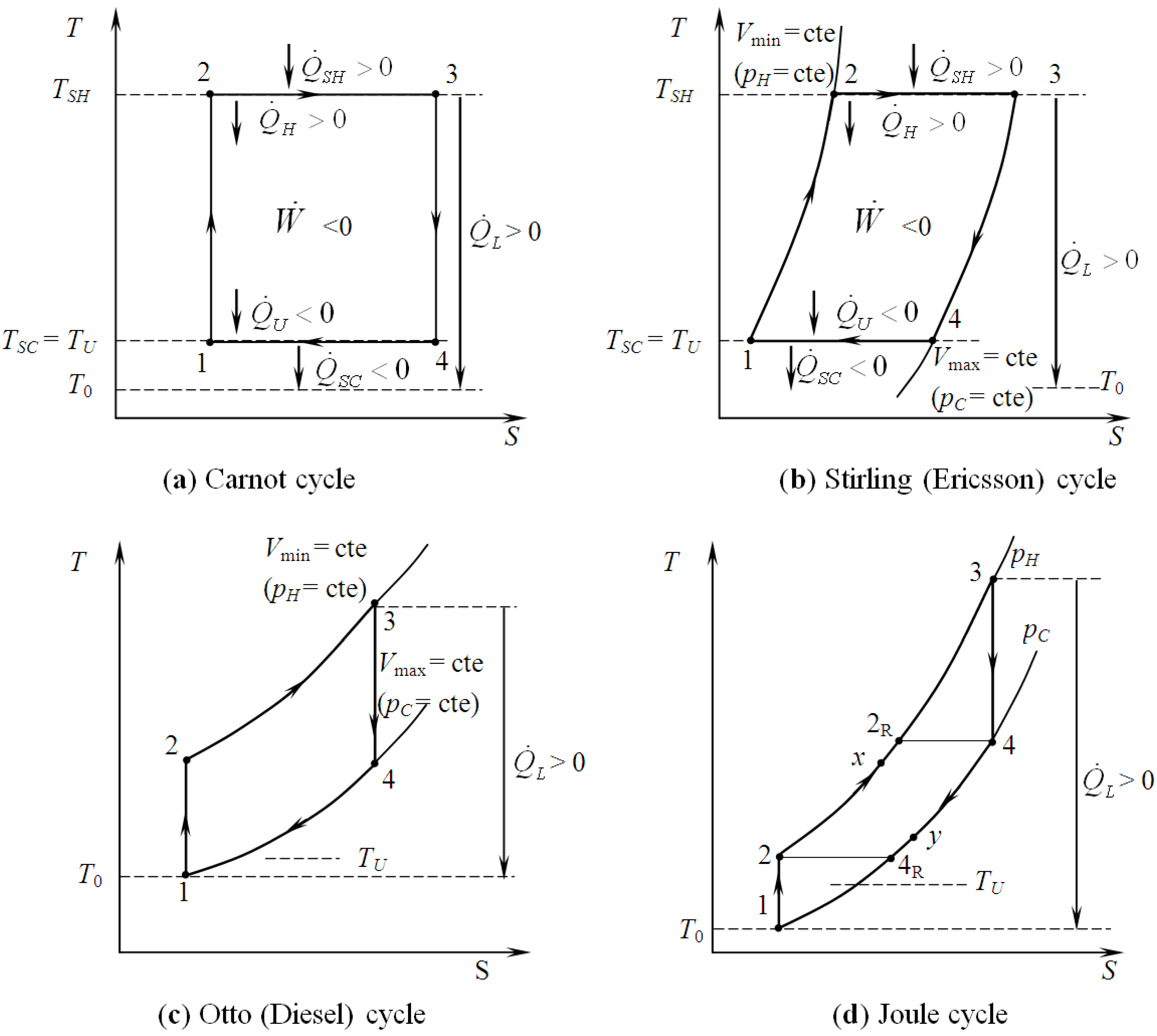
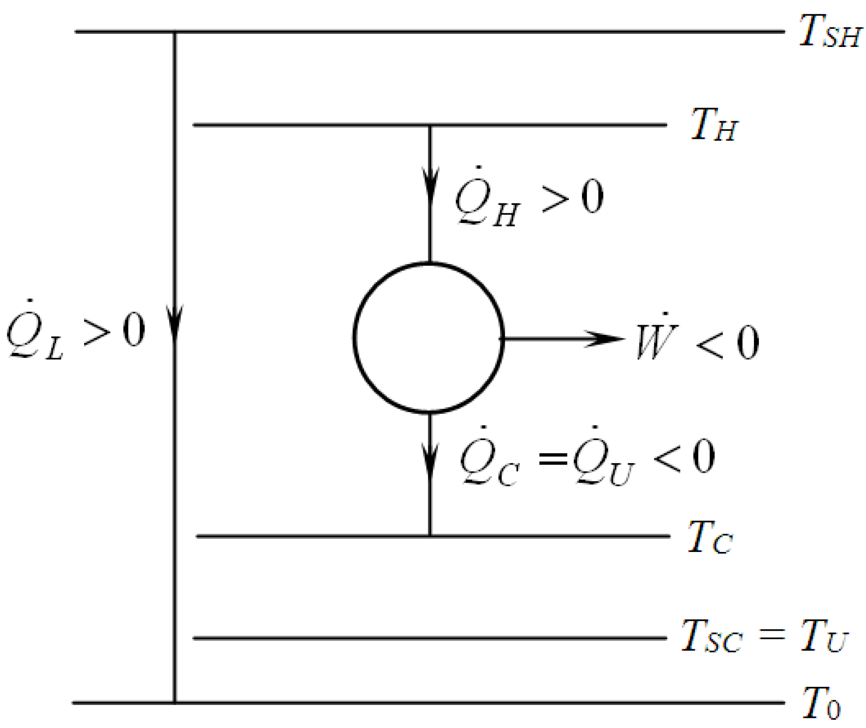
2. Modelling of Various CHP Systems

Combined Heat and Power systems with heat delivery as by-product are considered here. Although this represents a particular case of cogeneration, various processes are possible, characterized by systems or cycles referring to different techniques [26]. The first one developed was the CHP with vapour turbines that appears as an externally fired engine (by a boiler or a steam generator). Other kinds of external combustion engines will be considered hereafter, like Ericsson and Stirling ones. Current well developed CHP systems are composed of internal combustion engines of various sizes going from 1 kWelec to more than 1 MW for industrial or urban applications. The third main systems category used for cogeneration is based on gas turbines, and in this case post combustion could be used. Some more recent studied categories using Fuel Cells or Solar Photovoltaic arrays are also added to the previously mentioned ones.
The present analysis is deliberately limited to the main CHP categories, namely Vapour Turbines, External Combustion Engines, Internal Combustion Engines, and Gas Turbine Engine. All these systems are thermo-mechanical ones, each having a high temperature heat source. Generally, the heat is obtained by burning a fuel, whatever the fuel is. Mechanical and then electrical power is produced by the engine (the machine). According to the Second Law of Thermodynamics, the machine gives back heat (a part of the useful energy delivered by CHP, UE) to a cold sink, before rejecting the remaining heat to the environment at T0, the reference temperature.
The performances of four main engines acting as CHP systems will be compared hereafter. They are represented by the Carnot, Stirling or Ericsson, Otto or Diesel, and finally Brayton-Joule cycles [27]. Firstly, the model is developed by means of equilibrium thermodynamics, which provides more insight into the CHP system operation by considering heat losses and other irreversibilities. Also various possible performance criteria and constraints associated to the objective function that should be optimized are used in the model and will be presented in the next sections.

3. Criteria and Optimizations

The proposed models were developed for steady state operation assumption in order to get the upper bound of obtainable exergy rate of the useful energy delivered by the CHP system corresponding to a nominal design point. This is crucial to determine the corresponding exergetic efficiency at any rate. The two useful effects of CHP systems are the mechanical power, W ˙ and the useful heat transfer rate supplied to the consumer, Q ˙ U , both being negatives as the proposed sign convention states. In this sign convention each quantity entering the machine is positive, and each leaving quantity is negative.
In most cases the machines are non-adiabatic due to thermal losses to the environment. As a first attempt, lumped analysis suggests that these losses can be represented as an equivalent heat loss between the highest and lowest temperature of the system. They are summarized as Q ˙ L , heat transfer rate loss between the hot and cold side (positive quantity).

3.1. First Law Efficiency Criterion, ηICHP

Whatever the engine is, the energy balance can be written as follows (see Figure 1a):
Q ˙ S H + W ˙ + Q ˙ S C = 0
where Q ˙ S H is the heat transfer rate input, the so called energy rate consumption (EC), given by:
Q ˙ S H = Q ˙ H + Q ˙ L
and Q ˙ S C is the heat transfer rate rejected to the sink, expressed as:
Q ˙ S C = Q ˙ C Q ˙ L
with Q ˙ H , Q ˙ C the heat transfer rate entering, respectively leaving the converter.
The model assumption regarding the useful heat transfer rate provided by the engine in cogeneration mode operation corresponds to the ideal case of maximum heat transfer rate recovery that yields:
Q ˙ U = Q ˙ C
The first law efficiency ηICHP is defined as the ratio of the usable energy rate (UE) and the energy rate consumption, EC. By combining Equations (1), (3) and (4) the first law efficiency with cogeneration is given by:
Energies 05 03701 i001
The consequence is that the first law implies only a “non-adiabatic system efficiency” due to the presence of heat transfer rate loss, Q ˙ L , whatever the thermo-mechanical CHP system is. If the system is without losses, the limit ηICHP is one because of the ideal case of maximum heat transfer rate recovery that was considered, whatever the system is. However, one notes that if it could happen for external combustion engines (see Figure 1a,b), it is not the case of internal combustion engines (see Figure 1 c,d), due to the fact that corresponding engines are open systems and TU > T0. So, heat losses to ambient appear. These dissimilarities are due to the heat transfer particularities. Hence, useful heat could be delivered at constant temperature (TSC = TU) in cases a and b, but not for cases c and d, where finite heat source effects cannot be neglected.
Figure 1. Equilibrium Thermodynamics of CHP thermo-mechanical engines: (a) and (b) –ECE; (c) and (d) –ICE.
Energies 05 03701 g001
To conclude the temperature level of the useful heat appears important. It is why exergetic criteria have to be considered in the analysis.

3.2. Exergetic Criterion

Whatever the engine is, the exergy transfer rate of the usable energy is given by [27]:
Energies 05 03701 i002
The useful thermal exergy corresponds to the case where it is looked from the external utility side instead of the working fluid side. This remark confirms the difference between ECE and ICE, as mentioned in Section 3.1.
Then, the difference between the machine (engine) and the system from the exergetic point of view is indicated hereafter by using two entropy balances in the case of endo-irreversible thermodynamic approach. Their expressions are as follows:
for the engine:
Energies 05 03701 i003
for the non-adiabatic system:
Energies 05 03701 i004
where S ˙ i , internal entropy generation rate of the engine; S ˙ T , total entropy generation rate of the system including source and sink (the hypothesis is that the useful heat is finally delivered to the environment).
Upon combining Equations (7) and (8) and calculating, the total entropy generation rate expression of the CHP system results as:
Energies 05 03701 i005
The exergy rate consumed by the system is expressed as:
Energies 05 03701 i006
This result confirms the fact that the heat transfer rate loss due to internal irreversibilities, I ˙ i = T 0 S ˙ i , have a negative impact on the exergy efficiency of the system. The exergy efficiency of the engine is slightly different from that of the system due to the fact that E ˙ x C moves from the preceding expression to Energies 05 03701 i006. The same methodology will be applied to ICE hereafter.

3.3. General Optimization Procedure

By considering the same hypothesis introduced in Section 2, a two heat conductances model is develop here corresponding to the one proposed by Sahin and Kodal [28]. The model corresponds to the endoreversible case (without internal irreversibilities), and is also the basic configuration of the CHP vapour turbine system without losses. Then, by means of non-equilibrium Thermodynamics more insight in the CHP system operation is achieved by considering external heat transfer irreversibilities at source and engine contact and at engine and sink contact (Figure 2).
The engine entropy balance expression results as:
Q ˙ H T H + Q ˙ U T C = 0
It is clear that energy efficiency (equal to one in the ideal case without heat loss) does not depend on TU, nor TH, TC, but the system exergy efficiency does. By combining Equations (1) - (3), (6), (7), the exergy efficiency expression becomes:
Energies 05 03701 i007
Figure 2. Schematic representation of the temperature distribution in a non-equilibrium CHP Carnot system.
Energies 05 03701 g002
If Q ˙ H = Q ˙ S H is imposed, the maximum of efficiency gives back the equilibrium case (TC = TSC = TU; TH = TSH). But the necessary finite heat transfer rate imposes through the entropy balance a constraint relating the two degrees of freedom (TC, TH).
For the case of linear heat transfer law considered as an example, where:
Q ˙ H = K H ( T S H T H )
Q ˙ C = K C ( T U T C )
The optimization with respect to TC, TH by using Lagrangian method (for details of variational calculus see [29,30]) gives:
Energies 05 03701 i008
Energies 05 03701 i009
where the heat transfer conductances KH, KC are parameters associated to a given design.
Consequently one gets from Equation (6) combined with Equations (1)–(4), and (16):
Energies 05 03701 i010
Equation (17) corresponds to the endoreversible case without heat losses and shows that optimal exergy does not depend on the level of TU. Furthermore, a constrained dimension imposed to the system, namely the total heat transfer conductance, KH + KC = KT, for the case without heat losses, but with internal irreversibilities of the convertor yields for Equations (16) and (17) the following expressions:
Energies 05 03701 i011
Energies 05 03701 i012
This results in a new optimum regarding the finite heat transfer conductances when the total heat transfer conductance is fixed.
By derivation of Equation (19) the best allocation of heat transfer conductances corresponds to:
Energies 05 03701 i013
Equation (20) expresses that a maximum of the useful heat exergy is obtained at equipartition of the heat transfer conductances for the endoreversible case (without internal irreversibilities, S ˙ i = 0):
K H * = K C * = K T 2
Hence, the maximum exergy rate of the useful energy supplied by CHP results as:
Energies 05 03701 i014
One notes that if lim TC = TU is considered (Chambadal-Novikov limit [31,32]), KC tends to infinity, T H * = T 0 T S H whatever KH is. A numerical example considering TSH = 2000 K, T0 = 300 K, will get T H * = 100 60 ≈ 775 K which is closed to the common values used today. The main result is that Equation (22) is a useful upper bound for all the ECE cases.

4. Optimization with Constraints

The use and design of a CHP system is characterized by the ratio of useful heat transfer rate to useful power, R = Q ˙ U / W ˙ . Two other parameters can be added to this one corresponding to the two possible priorities, the mechanical power load, W ˙ 0 , or the useful heat load, Q ˙ U 0 . The last more significant case could be the hot source heat transfer rate limited to Q ˙ S H 0 . These alternatives correspond to one technical added constraint that suppresses one degree of freedom for the optimization. The four previously cited cases will be considered hereafter, and new corresponding results for the Carnot endoreversible CHP system without heat losses will be given.

4.1. Carnot CHP System with R Imposed

The optimization of the energy efficiency of CHP from a general point of view is the same as the optimization of the engine efficiency. By considering the ratio of useful heat transfer rate to useful power in the model and after some simple calculations, it comes for the endoreversible system:
T C T H = R 0 1 + R 0
where R0 is the imposed value of the R ratio whatever expressions are used for the heat transfer law, and the available heat transfer rate at hot source. In the frame of equilibrium thermodynamics, Equation (23) becomes:
T U T S H = R 0 1 + R 0
One notes that the ratio R0 is fundamentally related to the Carnot efficiency of the engine according to:
R 0 = 1 1 / η C
For linear heat transfer law (KH, KC -parameters) considered in the model, the corresponding exergy rate of the useful energy supplied by CHP results by combining Equations (6), (13), (14) and (24) as:
Energies 05 03701 i015
with:
X 0 = 1 + R 0 R 0
It is easy to demonstrate that optimum optimorum of useful effect is given again by Equation (22), but R0, TU, TSH are interrelated at the optimum by:
1 + R 0 R 0 T U = T S H T 0
This important relation means that for TSH parameter, R0 opt satisfies Equation (28) for a chosen TU or TU opt satisfies Equation (28) for an imposed R0.
Note that Equation (26) could be enlarged when an irreversibility ratio is considered. Its expression becomes:
Energies 05 03701 i016
This expression allows an optimum for a specific value of X0 relating TSH, T0 and TU, as expressed by Equations (27) and (28). This result is a new one. When imposing finite heat transfer conductances, KH + KC = KT, the conductance equipartition is found again for M A X | E ˙ x U   o p t | .

4.2. Carnot CHP System with W ˙ Imposed

The same methodology as for engine optimization [33] is used here, but by adding the constraint W ˙ = W ˙ 0 , an intermediate variable α appears:
Energies 05 03701 i017
The optimum of E ˙ x U corresponds to equipartition of heat transfer conductances previously found for an endoreversible system, and α opt satisfies the following equation that yields by combining Equations (14), (21), and (30) together with the constraint W ˙ = W ˙ 0 in Equation (6) and derivation with respect to TU:
Energies 05 03701 i018
The equilibrium thermodynamics limit is straight forward ( W ˙ 0 = 0 ), namely, the corresponding limit of the energy and exergy efficiency tends to one, for reversible and no heat losses operating regime.
If Energies 05 03701 i019, an interesting limit appears:
Energies 05 03701 i020
and the corresponding approximated E ˙ x U   o p t yields:
Energies 05 03701 i021
Equation (33) shows that the optimized exergy of the useful energy supplied by CHP is proportional to the imposed power W ˙ , but amplified by the temperature ratio (TSHT0)/(TSHTU).

4.3. Useful Heat Transfer Rate Imposed

The heat utility is the priority in this case by its imposed value, Q ˙ U = Q ˙ U 0 . By following the same steps as in Section 4.2, one finds that the optimum of E ˙ x U corresponds to the equipartition of heat transfer conductances, and αopt becomes:
Energies 05 03701 i022
The corresponding E ˙ x U   o p t results:
Energies 05 03701 i023
By derivation of Equation (35) with respect to TU, one can show that an optimum optimorum of E ˙ x U exists, but it requires:
Energies 05 03701 i024
Again, Equation (22) is valid for M A X | E ˙ x U   o p t | .

4.4. Heat Transfer Rate at the Source Imposed

The consumed heat transfer rate corresponds to the heat transfer rate input, which is now imposed, Q ˙ S H = Q ˙ S H 0 . The optimum exergy of the useful energy supplied by CHP associated to this constraint appears for conductance equipartition, and its expression is:
Energies 05 03701 i025
Here again a maximum maximorum exists and corresponds to:
Energies 05 03701 i026
It always leads to the Equation (22) for M A X | E ˙ x U   o p t | .

4.5. Partial Conclusion

The models presented in Section 4 point out that in the presence of constraints the optimum of the useful exergy function does exist and it is given by the Equations (26), (34), and (36). The optimum of these optima [Equation (22)], results by derivation of the previously mentioned relations and it corresponds to special values of the constrained parameters. The expression of M A X | E ˙ x U   o p t | does not depend on TU, but is proportional to KT that relates it to the size of the system.
Lastly an interesting constraint to discuss is when TSH = TMAX. It was shown that M A X | E ˙ x U   o p t | is an increasing function of TSH. Actually TSH is limited at a given value imposed by the thermomechanical strength of materials, which means that one cannot increase it as much as we want. Moreover, it is known that for non-adiabatic system this limitation corresponds to the stagnation temperature. This is a current practice for solar systems and it could be also for ICE, when considering the stagnation temperature to be less or equal to the adiabatic temperature of combustion. However for a non- adiabatic system, a new optimum exists, limited by the stagnation temperature of the system [29].
These extensions will be summarized hereafter (Section 5). It has been shown that it comes out from material limitations and it is designated by TMAX.

5. Discussion—Comparisons

Some results of the model will be exemplified in Table 1 with corresponding comments given hereafter. Extensive examination of CHP configurations using thermo-equilibrium thermodynamics does not exhibit the optima for the studied systems. Moreover, first law efficiencies are not appropriate to qualify performance of these systems, so that exergetic efficiencies are recommended. Actually, First Law analysis does not provide an optima of the useful energy rate. It is not the case for exergy analysis, where the heat quality is accounted. The present study has been done for evaluating the useful exergy rate in relation with finite dimensions of the system given by heat transfer conductances to allocate, and with the maximum allowed temperature for the system.

5.1. Thermodynamic Optimization of Carnot CHP Systems

It was shown that when Finite Dimensions of the systems are considered, and pre-established criteria are used, optimum configurations exist, relative to temperature distribution and design variables of the system (heat transfer conductances, heat transfer rate, heat exchanger effectiveness). The Carnot cycle was chosen to show the optimization results because it is generally the reference cycle regarding steam turbines. Also, the main constraints applied to the cycle appear to move strongly the obtained optimal results. In any cases we have got the same upper bound given by Equation (19). It represents the upper bound (reference) of the exergy rate obtainable for a Carnot CHP system related to finite size through the total heat transfer conductance, KT, and maximum temperature, TSH, with regard to environment temperature, T0.
The proposed model includes heat losses from the system to ambiance, and also internal irreversibilities of the converter. The internal irreversibilities can be considered by two ways, (1) through entropy rate created inside the system S ˙ i or (2) through an irreversibility ratio, which is the most used irreversibility representation. The Carnot CHP system extensions were reported in [29].
Table 1 gives the results obtained for the Carnot adiabatic CHP system and when the irreversibility ratio I is considered, and under various proposed added constraints. These results convey to the evidence that the optimal allocation of heat transfer conductances does not depend on the added constraints. In every case, the results differ from equipartition because:
Energies 05 03701 i027
The optimal temperature of the working fluid depends on the added constraint. The temperature TH opt is nondependent explicitly of TU, except when the ratio R = R0 is imposed. The objective function of the studied CHP systems is logically the exergy rate, E ˙ x U , of the useful energy delivered by CHP. It is composed by the sum of the useful mechanical exergy, W ˙ , and the useful heat exergy. Its optimal value is depending on the studied case, as given in Table 1.
The maximum maximorum of | E ˙ x U | corresponds to:
Energies 05 03701 i028
One notes that this value does not depend on TU, the useful heat temperature level. The same conclusion holds, if the entropy rate method is chosen:
Energies 05 03701 i029
Complementary results have been published, when the CHP system is a non adiabatic one. In that case, the maximum attainable temperature of the system, the stagnation temperature TS, is a useful quantity to be introduced. Hence, a new compromise between the heat transfer conductances and the heat losses has been defined (see [29] for some details).
Table 1. Carnot CHP system optimization, with added constraint, and irreversibility ratio method.
optimumTH optTC opt | E ˙ x U | o p t
Added constraint
without Energies 05 03701 i030 Energies 05 03701 i031 Energies 05 03701 i032
Q ˙ H = Q ˙ H 0 Energies 05 03701 i033 Energies 05 03701 i034 Energies 05 03701 i035
R = R0 Energies 05 03701 i036 Energies 05 03701 i037 Energies 05 03701 i038
W ˙ = W ˙ 0 * Energies 05 03701 i039 Energies 05 03701 i040 Energies 05 03701 i041
Q ˙ U = Q ˙ U 0 * Energies 05 03701 i042 Energies 05 03701 i043 Energies 05 03701 i044
* Some details regarding the derivation of αopt expression are given in the Appendix.

5.2. Optimization of Other CHP Configurations

As can be seen in Figure 1, a Stirling or Ericsson engine is an externally fired CHP system. Hence, the results have great similarity with the previous examined ones (Section 4). Complementary results could be found in a recent report [34]. Contrarily Otto (Diesel) CHP systems, as well as Joule CHP systems, are internally fired. Due to this common issue, an insight to CHP system based on gas turbine engine is given hereafter. The optimization corresponds to the constraint of TMAX, the maximum imposed temperature, as it is well known that this condition is actually the most limiting one for gas turbines, in order to preserve material properties.
Details of the model can be found in a recently published paper [35]. The heat exchangers model uses the NTU-effectiveness model: the corresponding effectiveness is εR for recuperator and εU for the useful heat exchanger. For the Joule CHP system cycle illustrated in Figure 1d, the First Law has the same expression remains as for all ICE engines:
W ˙ + Q ˙ H + Q ˙ U + Q ˙ C = 0
where:
Q ˙ H = C ˙ ( T M A X T X )
where C ˙ = m ˙ · c p is the heat capacity rate of the working fluid in the cycle, and:
T X = ε R · T 4 + ( 1 ε R ) · T 2
The rejected heat transfer rate from the turbine is:
Q ˙ U + Q ˙ C = C ˙ ( T 0 T Y )
with:
T Y = T 4 · ( 1 ε R ) + ε R · T 2
By combining Equations (42)−(46) the mechanical power is:
Energies 05 03701 i045
where T2 results from Equation (7) after some calculations:
T 2 = T M A X T 0 k T 4
and the irreversibility factor is given by:
k = exp [ S ˙ i / C ˙ ]
By taking into account the above expressions, Equation (6) becomes for this case:
Energies 05 03701 i046
The optimum exergy rate of the useful energy supplied corresponds to the derivation of Equation (50) with respect to T2 or T4 that are related by Equation (48). One can easily get:
Energies 05 03701 i047
Energies 05 03701 i048
with:
Energies 05 03701 i049
Energies 05 03701 i050
The corresponding M A X | E ˙ x U | is obtained from Equations (50)–(52) as:
Energies 05 03701 i051
Equation (55) allows to one to determine the maximum exergy rate of the useful energy supplied depending on system parameters, namely the effectiveness of the recuperator and useful heat HEX, temperatures and the irreversibility factor.
All the results detailed in this section are relative to the gas turbine engine configuration where the recuperator and the useful heat HEX are connected in series at the turbine exit. Therefore, the temperatures constraint should be: TU < TY < T4, in order to ensure the optimisation solution.
Some limit cases are interesting to note for the previously reported Joule CHP systems:
  • perfect heat recuperation given by εR = 1. It involves:
    Energies 05 03701 i052
The maximum exergy rate of the useful energy supplied (Equation (55)) results as:
Energies 05 03701 i053
  • perfect useful heat HEX provided by εU = 1. It involves:
    Energies 05 03701 i054
For this case Equation (55) with a = aR and b = bR provides the optimum result.
  • perfect heat exchangers: εR = 1 and εU = 1. It involves:
    a = 1   ; b = T 0 T U
and:
Energies 05 03701 i055
Equation (60) constitutes an upper bound depending on the three temperatures (T0, TU, TMAX) and also considering the cycle irreversibilities by the factor k. The endoreversible operation corresponding to k = 1 is straightforward.
  • no heat recuperation: εR = 0. For this case:
    Energies 05 03701 i056
and Equation (55) yields:
Energies 05 03701 i057
Figure 3. Evolution of the non-dimensional optimum temperature at the turbine exit, t 4 * , as a function of TU for TMAX variable.
Energies 05 03701 g003
Figure 4. Evolution of t 4 * as a function of tU for irreversibility factor k as variable.
Energies 05 03701 g004
Note that a0 = bR, so one could say that Equation (57) is identical to Equation (62). Although they are formally identical, the provided optimum is different due to the variation range of TU which is greater for the present case compared to the previous one (εR = 1). Other gas turbine CHP systems were studied and these results are currently in press [36,37].
Figure 3 and Figure 4 illustrate the influence of TU level on the optimum temperature T4 at the turbine exit, for different values of the non-dimensional maximum allowed temperature, respectively, irreversibility factor, k. Note that the main parameter of the model is the non-dimensional temperature corresponding to the useful heat temperature level, given by:
t U = T U T 0
and the non-dimensional value of the maximum allowed temperature with respect to the ambient one, is:
t M A X = T M A X T 0
So, if the non-dimensional useful heat temperature level, tU, increases, the optimal non-dimensional temperature t4 diminishes. This decrease is more pronounced as tMAX increases (Figure 3), and remains proportional as k increases (Figure 4). Otherwise, t4 opt increases with the allowed tMAX. For example, the non-dimensional optimum temperature at the turbine exit increases twice when the non-dimensional value of the maximum allowed temperature with respect to the ambient one increases from 2 to 8. Also, t4 opt increases significantly with the internal irreversibility of the turbine that corresponds to the decrease of k (Figure 4). Hence, an almost constant growth of 0.35 is registered by t4 opt when k decreases with 0.25. These models are presently under development.

6. Conclusions

The thermodynamics of Combined Heat and Power Systems has been reviewed, with a particular focus on the most common ones which are the thermo-mechanical systems. Two main categories were proposed:
-
ECE, External Combustion Engine;
-
ICE, Internal Combustion Engine;
Optimization criteria for these systems are reviewed. The analysis confirmed that the First Law efficiency criterion is only representative of the system thermal losses (non-adiabatic operation), so it is recommended to use exergy efficiency, that takes into account the heat quality, and also qualifies the irreversibilities of the converter (engine) or of the system depending on the model used (Section 3.2). Hence, the exergy analysis is revealed by the present report to be the main tool for CHP systems study due to simultaneous consideration of work and heat by their exergy, that differs for the heat from its value.
Furthermore, it was shown by the mathematical approach particularized for Carnot system that optimization could be performed only if the finite size of the system is considered; equilibrium thermodynamics being not able to provide optima. The finite size optima obtained are coherent with the observed ones.
Various significant added constraints were proposed, they being useful for the design of specific systems and allowing to precise the influence on the design of the model parameters. Upper bound of the exergy rate of the usable energy were determined by consideration of the main constraints of the CHP systems: (1) imposed heat to power ratio R0; (2) imposed useful power W ˙ 0 (electrical or mechanical priority), (3) imposed useful heat transfer rate Q ˙ U 0 (heat demand priority), and lastly (4) imposed available source heat transfer rate Q ˙ S H 0 . The main tendencies for Carnot CHP system were presented in Table 1 proving the optima existence and showing the dependence on the model parameters of the optimum temperatures of the working gas at source and sink, and of the optimum exergy rate of the usable energy.
The upper bound of the exergy rate of the useful energy delivered by the Carnot CHP system was obtained [Equation (22)]. It is a very important result, as it is the equivalent of the “nice radical” of Curzon-Ahlborn approach. Also, its expression contains the total heat transfer conductance to be allocated to the system that appears as the size factor of the maximum exergy rate.
Among other CHP systems that have been examined, the Gas Turbine Engine-based one is considered the more representative CHP system for industrial applications. The corresponding optimum of the exergy rate of the useful energy delivered by the CHP system was derived and the upper bound was determined in the case where maximum temperature of the working gas, TMAX, is fixed. This case is the most significant for the present state of the art of Gas Turbine Engine. The expressions of the optimum exergy rate of the useful energy delivered to the consumer were presented for several limiting case, and have shown the dependence on the recuperator and useful heat exchanger effectiveness, temperatures TMAX, TU, T0, and internal irreversibilities by the internal entropy generation rate, S ˙ i .
The Gas Turbine Engine CHP system illustrates the Internal Combustion Engine CHP configuration. Thus, the present methodology could be applied to Otto or Diesel CHP configurations appropriate for small and household applications. Further extension of these models is presently under development in order to allow the comparison of different constrained cases and to offer an overview on the performance of various existing CHP systems.

Nomenclature

C ˙
heat capacity rate [W K−1];
cp
mass specific heat at constant pressure [W kg−1 K−1];
E ˙ X
exergy rate [W];
m ˙
mass flow rate of the working gas in the cycle [kg s−1];
I
irreversibility ratio;
K
heat transfer conductance [W K−1];
NTU
number of heat transfer units;
Q ˙
heat transfer rate [W];
R
ratio of useful heat transfer rate to useful power;
S ˙
entropy rate [W K−1];
T
temperature [K];
t
no dimensional temperature;
X
temperature difference [K];
W ˙
mechanical power [W];

Greek symbols 

ε
heat exchanger effectiveness;
η
efficiency;
α
intermediate variable;

Subscripts and superscripts 

C
related to the working fluid, at the sink;
c
consumed or Carnot;
CHP
combined heat and power system;
ECE
external combustion engine;
ex
exergetic;
GT
gas turbine;
H
related to the working fluid, at the source;
i
internal;
ICE
internal combustion engine;
L
loss;
PV/T
photovoltaic/thermal system;
R
recuperator;
SH
source;
SC
sink;
T
total;
U
useful;
I
related to first law;
0
ambient or imposed value;
*
optimal

Appendix

This annex gives the αopt value announced in Table 1:
If W ˙ = W ˙ 0 < 0
αopt is the solution of the equation:
a α 2 b α c = 0
with:
Energies 05 03701 i058
Energies 05 03701 i059
Energies 05 03701 i060
If Q ˙ U = Q ˙ U 0 < 0
α o p t = d 1 + d
with:
Energies 05 03701 i061

References

  1. Wakui, T.; Yokoyama, R. Optimal sizing of residential gas engine cogeneration system for power interchange operation from energy-saving viewpoint. Energy 2011, 36, 3816–3824. [Google Scholar] [CrossRef]
  2. Radulescu, M. Combined Electricity and Heat Production Systems with PEMFC or SOFC Fuel Cells and External Vapor Reforming. Ph.D. Thesis, Nancy University, Nancy, France, September 2006. [Google Scholar]
  3. Milia, D.; Sciubba, E. Exergy-based lumped simulation of complex systems: An interactive analysis tool. Energy 2006, 31, 100–111. [Google Scholar] [CrossRef]
  4. Descieux, D. Modelling and Exergetic Comparison of Cogeneration Systems. Ph.D. Thesis, Nancy University, Nancy, France, November 2007. [Google Scholar]
  5. Pehnt, M. Environmental impacts of distributed energy systems—The case of micro cogeneration. Environ. Sci. Policy 2008, 11, 25–37. [Google Scholar] [CrossRef]
  6. Abusoglu, A.; Kanoglu, M. First and second law analysis of diesel engine powered cogeneration systems. Energy Convers. Manag. 2008, 49, 2026–2031. [Google Scholar] [CrossRef]
  7. Zhai, H.; Dai, Y.J.; Wu, J.Y.; Wang, R.Z. Energy and exergy analyses on a novel hybrid solar heating, cooling and power generation system for remote areas. Appl. Energy 2009, 86, 1395–1404. [Google Scholar] [CrossRef]
  8. Abusoglu, A.; Kanoglu, M. Exergoeconomic analysis and optimization of combined heat and power production: A review. Renew. Sustain. Energy Rev. 2009, 13, 2295–2308. [Google Scholar] [CrossRef]
  9. Aussant, C.D.; Fung, A.S.; Ugursal, V.I.; Taherian, H. Residential application of internal combustion engine based cogeneration in cold climate—Canada. Energy Build. 2009, 41, 1288–1298. [Google Scholar] [CrossRef]
  10. Nieminen, J.; Dincer, I. Comparative exergy analyses of gasoline and hydrogen fuelled ICEs. Int. J. Hydrogen Energy 2010, 35, 5124–5132. [Google Scholar] [CrossRef]
  11. El-Emam, R.S.; Dincer, I. Energy and exergy analyses of a combined molten carbonate fuel cell—Gas turbine system. Int. J. Hydrogen Energy 2011, 36, 8927–8935. [Google Scholar] [CrossRef]
  12. Bingöl, E.; Kılkış, B.; Eralp, C. Exergy based performance analysis of high efficiency poly-generation systems for sustainable building applications. Energy Build. 2011, 43, 3074–3081. [Google Scholar] [CrossRef]
  13. Doluweera, G.H.; Jordaan, S.M.; Moore, M.C.; Keith, D.W.; Bergerson, J.A. Evaluating the role of cogeneration for carbon management in Alberta. Energy Policy 2011, 39, 7963–7974. [Google Scholar] [CrossRef]
  14. Barelli, L.; Bidini, G.; Gallorini, F.; Ottaviano, A. An energetic–Exergetic comparison between PEMFC and SOFC-based micro-CHP systems. Int. J. Hydrogen Energy 2011, 36, 3206–3214. [Google Scholar] [CrossRef]
  15. Ji, J.; Liu, K.; Chow, T.T.; Pei, G.; He, H. Thermal Analysis of PV/T Evaporator of A Solar Assisted Heat Pump. Int. J. Energy Res. 2007, 31, 525–545. [Google Scholar] [CrossRef]
  16. Thilak Raj, N.; Iniyan, S.; Goic, R. A review of renewable energy based cogeneration technologies. Renew. Sustain. Energy Rev. 2011, 15, 3640–3648. [Google Scholar] [CrossRef]
  17. Ibrahim, A.; Othman, M.Y.; Ruslan, M.H.; Mat, S.; Sopian, K. Recent advances in flat plate photovoltaic/thermal (PV/T) solar collectors. Renew. Sustain. Energy Rev. 2011, 15, 352–365. [Google Scholar] [CrossRef]
  18. Obernberger, I.; Carlsen, H.; Biedermann, F. State of the Art and Future Developments Regarding Small Scale Biomass CHP Systems with a Special Focus on ORC and Stirling Engine Technologies. In Proceedings of the 2003 International Nordic Bioenergy Conference, Jyväskylä, Finland, 2–5 September 2003.
  19. Uddin, S.N.; Barreto, L. Biomass-fired cogeneration systems with CO2 capture and storage. Renew. Energy 2007, 32, 1006–1019. [Google Scholar] [CrossRef]
  20. Zhang, X.; Su, S.; Chen, J.; Zhao, Y.; Brandon, N. A new analytical approach to evaluate and optimize the performance of an irreversible solid oxide fuel cell-gas turbine hybrid system. Int. J. Hydrogen Energy 2011, 36, 15304–15312. [Google Scholar] [CrossRef]
  21. Vuillecard, C.; Hubert, C.E.; Contreau, R.; Mazzenga, A.; Stabat, P.; Adnot, J. Small scale impact of gas technologies on electric load management—μCHP & hybrid heat pump. Energy 2011, 36, 2912–2923. [Google Scholar] [CrossRef]
  22. Lowe, R. Combined heat and power considered as a virtual steam cycle heat pump. Energy Policy 2011, 39, 5528–5534. [Google Scholar] [CrossRef]
  23. Wang, J.J.; Jing, Y.Y.; Zhang, C.F. Weighting Methodologies in Multicriteria Evaluations of CHP Systems. Int. J. Energy Res. 2009, 33, 1023–1039. [Google Scholar] [CrossRef]
  24. Chua, K.J.; Yang, W.M.; Wong, T.Z.; Ho, C.A. Integrating renewable energy technologies to support building trigeneration—A multi-criteria analysis. Renew. Energy 2012, 41, 358–367. [Google Scholar] [CrossRef]
  25. Rubio-Maya, C.; Uche-Marcuello, J.; Martínez-Gracia, A.; Bayod-Rújula, A.A. Design optimization of a polygeneration plant fuelled by natural gas and renewable energy sources. Appl. Energy 2011, 88, 449–457. [Google Scholar] [CrossRef]
  26. Lévy, C. Les techniques de cogénération. In Techniques de l’Ingénieur, Traité de Génie Energétique; Editions TI: Paris, France, 1996; pp. 1–24. [Google Scholar]
  27. Feidt, M. L’Integration des Systèmes Energétiques. In Energétique; Dunod: Paris, France, 2006; pp. 889–909. [Google Scholar]
  28. Sahin, B.; Kodal, A. Recent Advances in Finite Time Thermodynamics; Wu, C., Chen, L., Chen, J., Eds.; Nova Science Publishers: New York, NY, USA, 1999; pp. 289–299. [Google Scholar]
  29. Feidt, M. Optimal Thermodynamics—New Upper Bounds. Entropy 2009, 11, 529–547. [Google Scholar] [CrossRef]
  30. Feidt, M.; Lang, S. Conception optimale de systèmes combinés à génération de puissance, chaleur et froid. Entropie 2002, 242, 2–11. [Google Scholar]
  31. Chambadal, P. Les Centrales Nucléaires; Armand Colin: Paris, France, 1957; pp. 41–58. [Google Scholar]
  32. Novikov, I.I. The Efficiency of Atomic Power Stations. J. Nucl. Energy 1958, 7, 125–128. [Google Scholar]
  33. Feidt, M.; Costea, M.; Petre, C.; Petrescu, S. Optimization of Direct Carnot Cycle. Appl. Therm. Eng. 2007, 27, 829–839. [Google Scholar] [CrossRef]
  34. Samba, A. Microcogeneration: Thermodynamic Optimization and Adaptability to Different Fuels. M.Sc. Thesis, Ecole des Mines, Nancy, France, February 2010. [Google Scholar]
  35. Feidt, M.; Costea, M.; Postelnicu, V. Comparison between the Brayton Cycle with Imposed Thermal Input and Maximal Temperature Constraint. Oil Gas Sci. Technol. Rev. 2006, 61, 237–247. [Google Scholar] [CrossRef]
  36. Costea, M.; Feidt, M.; Alexandru, G.; Descieux, D. Optimization of Gas Turbine Cogeneration System for Various Heat Exchanger Configurations. Oil Gas Sci. Technol. Rev. 2012, 67, 517–535. [Google Scholar] [CrossRef]
  37. Tirca-Dragomirescu, G.; Costea, M.; Feidt, M.; McGovern, J.; Dobrovicescu, A.; Tutica, D.; Kheiri, A. Modelling and Optimization of Heat Exchangers within Gas Turbine Systems. In Proceedings of Engineering Systems Design and Analysis Conference (ESDA 2012), Nantes, France, 2–4 July 2012.

