Article

Simulation Research on an Electric Vehicle Chassis System Based on a Collaborative Control System

1
National Engineering Laboratory for Electric Vehicles, Beijing Institute of Technology, Beijing 100081, China
2
College of Environmental and Energy Engineering, Beijing University of Technology, Beijing 100124, China
*
Author to whom correspondence should be addressed.
Energies 2013, 6(1), 312-328; https://doi.org/10.3390/en6010312
Submission received: 16 October 2012 / Revised: 24 December 2012 / Accepted: 7 January 2013 / Published: 14 January 2013

Abstract

:
This paper presents a collaborative control system for an electric vehicle chassis based on a centralized and hierarchical control architecture. The centralized controller was designed for the suspension and steering system, which is used for improving ride comfort and handling stability; the hierarchical controller was designed for the braking system, which is used for distributing the proportion of hydraulic braking and regenerative braking to improve braking performance. These two sub-controllers function at the same level of the vehicle chassis control system. In order to reduce the potential conflict between the two sub-controllers and realize a coordination optimization of electric vehicle performance, a collaborative controller was built, which serves as the upper controller to carry out an overall coordination analysis according to vehicle signals and revises the decisions of sub-controllers. A simulation experiment was carried out with the MATLAB/Simulink software. The simulation results show that the proposed collaborative control system can achieve an optimized vehicle handling stability and braking safety.

1. Introduction

To improve vehicle performance further, more and more active control systems such as the anti-lock braking system (ABS), active suspension system (ASS) and electric power steering (EPS), have been developed and many of them have been commercially utilized for nearly three decades [1,2,3]. Since there is no single system that can be effective over the entire range of vehicle operating conditions [4], more and more individual control systems are used, which are designed for some special functions, making the interference between them and a complicated systematic control unavoidable, thus restricting and deteriorating the vehicle performance. It is known that the improvement of vehicle dynamics predominantly depends on the coordinated work of various vehicle control subsystems [5]. Therefore, there is a tendency to integrate the individual subsystems for guaranteeing and further enhancing the vehicle performance. This has become a research focus in the field of vehicle dynamics control.
The key of the integrated vehicle chassis control research is control architecture, which can be divided into three main kinds: decentralized, centralized and hierarchical architecture [6,7]. Decentralized control only shares the sensor information and each subsystem still works independently; although the degree of integration of this type of control is the lowest, usually its reliability is the highest. Centralized control uses a global controller instead of many sub-controllers to give all subsystems control signals; this control architecture, which is usually used for the integration control of two close coupling subsystems such as suspension system and steering system, has the highest degree of integration and the lowest reliability usually [8]. Hierarchical control is somewhere between decentralized and centralized control in both integration degree and reliability; an upper controller is added to this control architecture based on retaining the original sub-controllers, although hierarchical control is mainly applied in the coordination of multiple subsystems at present, its control function is still limited. Consequently, separate research in the three above-mentioned control architectures is limited, and an ideal integrated system control architecture should contain decentralized, centralized and hierarchical control simultaneously [7].
Recently, the research on integrated control of chassis system is fairly common in conventional vehicles, but seldom done in electric vehicles. In this paper, a coupling of electric vehicle subsystems is provided for cornering regenerative braking conditions, ASS, EPS and electro-hydraulic braking systems are taken as the research object, and a collaborative control system which contains both centralized and hierarchical architecture is designed and the corresponding collaborative control strategy of an electric vehicle chassis system is established, which includes a centralized controller for the suspension and steering system based on Linear-Quadratic Gaussian (LQG) theory and a hierarchical controller for the braking system. The simulation results showed that the designed collaborative control strategy could provide a trade-off control among subsystems and improve the overall performance of electric vehicle further.

2. Modeling the Chassis System

2.1. Vehicle Dynamics Model

The vehicle dynamics includes the movement and rotation on the lateral, vertical and longitudinal directions; therefore, the vehicle lateral, vertical and longitudinal dynamics must be considered for a complete vehicle model. The vehicle dynamics model adopted here contains 14 degrees of freedom as shown in Figure 1, with the assumption of a vehicle’s small angular movements.
Figure 1. Vehicle dynamics model: (a) Vehicle reference coordinate system; (b) Vehicle side view; (c) Vehicle top view.
Energies 06 00312 g001
The 14 degrees of freedom includes heave, pitch, roll of sprung mass, vehicle yaw, lateral and longitudinal motion, four wheels vertical and rotation movement. According to Newton’s law, the motion equations of the vehicle are derived as follows:
(1) Sprung mass heave movement:
m s Z ¨ s = i = 1 4 F i
where Zs is sprung mass vertical displacement, ms is sprung mass, and Fi is the total suspension force.
(2) Sprung mass pitch movement:
I y s θ ¨ = ( F 1 + F 2 ) ( l f c s ) + ( F 3 + F 4 ) ( l r + c s )
where θ is sprung mass pitch angle, Iys is sprung mass rotary inertia around its centroid lateral axis, cs is distance from sprung mass centroid to vehicle mass centroid, lf , lr are the distances from vehicle mass centroid to the front and rear axles, respectively.
(3) Sprung mass roll movement:
I x u φ ¨ m s h v ˙ m s g h φ = d f 2 ( F 1 F 2 ) + d r 2 ( F 3 F 4 )
where φ is sprung mass roll angle, Ixu is sprung mass rotary inertia around the vehicle centroid vertical axis, v is lateral velocity of vehicle centroid, df, dr are the track distances of front and rear axles, h is vertical distance from sprung mass centroid to the roll axis.
(4) Vehicle yaw movement:
I z ω ˙ I z x φ ¨ = l f ( F y 1 + F y 2 ) l r ( F y 3 + F y 4 )
where ω is vehicle centroid yaw rate, Iz is vehicle mass rotary inertia around its centroid vertical axis, Izx is the product of inertia in vehicle mass centroid’s longitudinal and vertical directions, Fyi is tyre lateral force.
(5) Vehicle longitudinal movement:
m u ˙ = ( F x 1 + F x 2 ) cos δ ( F y 1 + F y 2 ) sin δ + F x 3 + F x 4
where u is longitudinal velocity of vehicle centroid, m is vehicle mass, Fxi is tyre longitudinal force, δ is front wheel corner angle.
(6) Vehicle lateral movement:
m ( v ˙ + u ω ) m s h φ ¨ = ( F y 1 + F y 2 ) cos δ + F y 3 + F y 4
(7) Four wheels’ vertical movement:
m u i Z ¨ 1 i = K u i ( Z 0 i Z 1 i ) F i   ( i = 1 , 2 , 3 , 4 )
where Z1i is unsprung mass vertical displacement, Z0i is ground displacement input, mui is unsprung mass, Kui is unsprung mass equivalent stiffness.
(8) Four wheels’ rotation movement:
I w i ω ˙ w i = F x b i r w T b i T m i F z i f r w    ( i = 1 , 2 , 3 , 4 )
where ωwi is wheel angular velocity, Iwi is wheel rotation inertia, rw is rolling radius of the tyre, Tbi is hydraulic braking torque, Tmi is motor regenerative braking torque, Fzi is tyre vertical load, f is the rolling resistance coefficient.
(9) The ground braking force can be calculated as:
F x b i = F x i cos δ + F y i sin δ
where Fxbi is ground the braking force.

2.2. Active Suspension Model

The total suspension force can be calculated as:
F i = K s i ( Z 1 i Z 2 i ) + C b i ( Z ˙ 1 i Z ˙ 2 i ) + f i   ( i = 1 , 2 , 3 , 4 )
where fi is the active suspension force, Ksi is the spring stiffness of suspension, Cbi is the damping coefficient of shock absorber, Z2i is the vertical displacement of sprung mass endpoint.
Supposed that the roll angle φ and the pitch angle θ change in a small range, then the endpoints displacement of the sprung mass will be expressed as follows:
{ Z 2 i = Z s c f θ ± 1 2 d f φ ( i = 1 , 2 ) Z 2 i = Z s + c r θ ± 1 2 d r φ   ( i = 3 , 4 )
where cf , cr are the distances from sprung mass centroid to front and axles, respectively.

2.3. Electric Power Steering Model

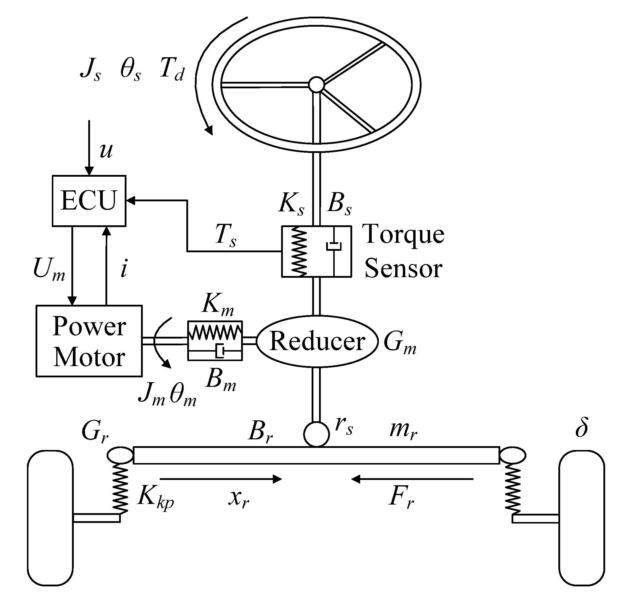
The shaft-assisted EPS system is used in this paper, a rack and pinion transmission is designed as the steering transmission. Its structure is shown in Figure 2.
Figure 2. Electric power steering system structure.
Energies 06 00312 g002
According to Newton’s law, the governing equations of motion for the EPS are derived as follows [9]:
(1) Motion equations of steering shaft are expressed as:
{ J s θ ¨ s + B s θ ˙ s + T s = T d T s = K s ( θ s x r r s )
where θs is steering shaft angle, Js is rotary inertia of steering shaft, Bs is steering shaft damping coefficient, Ts is steering shaft actual torque, Td is steering shaft input torque, Ks is steering shaft stiffness coefficient, xr is rack displacement, rs is pinion radius.
(2) Motion equations of rack and pinion are expressed as:
{ m r x ¨ r + B r x ˙ r + F r = K s r s ( θ s x r r s ) + K m G m r s ( θ m x r r s G m ) F r = K k p G r ( x r G r δ ) δ = θ s i s
where mr is effective mass of rack and tyre, Br is rack damping coefficient, Fr is steering system resistance, Km is motor torsional stiffness, Gm is gear ratio of the motor reducer, Kkp is stiffness coefficient of rack to steering, Gr is transmission ratio of rack to steering wheel, is is total transmission ratio of steering system.
(3) Motion equations of the assist motor are expressed as:
{ J m θ ¨ m + B m θ ˙ m + K m ( θ m x r r s G m ) = K a i L i ˙ + R i + K v θ ˙ m = U m
where θm is assistance motor angle, i is motor armature current, Jm is motor rotary inertia, Bm is motor damping coefficient, Ka is motor torque coefficient, Kv is EMF coefficient of motor, L is motor coil inductance, R is armature resistance, Um is motor terminal voltage.

2.4. Anti-Lock Braking System Model

In this paper, the ABS model is established according to its work principle, namely the process of cylinder supercharging, pressure maintaining and decompressing as follows [10]:
T b = d P w d t K f
where Pw is the wheel cylinder pressure during braking, Kf is braking efficiency factor:
d P w d t = { U i 0 U d
where Ui , Ud are the pressure change rate of the wheel cylinder in the supercharged process and decompression process, respectively.

2.5. Wheel Motor Model

The brushless DC motor has the characteristics of low speed and high torque. From a control point of view, as the current of each phase is a square wave, the inverter voltage can be simply controlled with a DC PWM wave method [11]. Therefore, the brushless DC motor is adopted as the wheel motor and its model is built as follows [12]:
G ( s ) = T m T m * = n p Φ r ( L m L s ) s + R s 1 T p w m s + 1
where Tm* is target electromagnetic torque, np is the number of motor poles, Φr is rotor flux, Lm is mutual-inductance between arbitrary two-phase windings of stator, Ls is self-inductance of each phase stator winding, Rs is phase resistance, Tpwm is the PWM switching cycle of brushless DC motor.

2.6. Tyre Model

As the only vehicle component generating external force that can be effectively manipulated to affect vehicle motions, tyres are crucial for vehicle dynamics and control [4]. The tyre dynamics are usually modeled with the “Magic Formula” developed by Pacejka et al. [13] which employs combinations of trigonometric functions to describe the tyre forces exactly. In this model, the tyre longitudinal force and lateral force are described as the complex nonlinear function of the tyre vertical load, slip rate and slip angle. Thus, the tyre model which combines longitudinal and lateral forces can be expressed as the following equations by ignoring self-aligning moment:
F x = σ x σ F x 0 ,   F y = σ y σ F y 0
σ = σ x 2 + σ y 2 ,   σ x = λ 1 + λ ,   σ y = tan α 1 + λ
F x 0 = D sin { C arctan [ B λ E ( B λ arctan B λ ) ] }
{ F y 0 = D sin { C arctan [ B x E ( B x arctan B x ) ] } + S v x = α + S h
where B, C, D, E, Sv and Sh are the stiffness, shape, peak, curvature, horizontal drift and vertical drift factor, respectively. All of them are described as the function of the tyre vertical load Fz, tyre slip rate λ and tyre slip angle α.

2.7. Road Input Model

The time-domain road input model, which is mainly divided into integral white noise and filtered white noise, is used to generate random road roughness input. The filtered white noise can be a true reflection of the actual situation which road spectrum approximates horizontal within a low frequency range [14].The road input model is listed as follows:
Z ˙ 0 i = 2 π f 0 Z 0 i + 2 π G 0 u w ( t )
where G0 is the road roughness coefficient, f0 is the lower cutoff frequency, w(t) is zero mean Gaussian white noise.

3. Chassis Collaborative Control System

3.1. Collaborative Control Definition

For the chassis system control, the centralized controllers are established for the subsystems (normally two) which have close relationship and high coupling effect according to their own dynamics in order to enhance the degree of integration, the hierarchical controllers are established for such subsystems that have exact coupling relationships and are difficult to control in a centralized way. The decentralized controllers are established for those subsystems that are difficult to control in a centralized way or in a hierarchical way according to their own dynamic effects. The centralized, hierarchical and decentralized controllers are all usually regarded as the low-level sub-controllers, and an extra upper controller is responsible for the unified control of the sub-controllers, to coordinate the control conflicts and improve the overall performance of the chassis system. Herein, we define this kind of chassis control method as the collaborative control.

3.2. Electric Vehicle Chassis System Collaborative Control Strategy
In this paper, the collaborative control strategy of ASS, EPS and electro-hydraulic braking system is given as follows: a centralized controller is designed for ASS and EPS without considering the impact of the electro-hydraulic braking system, and it can simultaneously analyze and optimize the control target under the coupling effect of electric vehicle lateral dynamics and vertical dynamics during the steering process, and a hierarchical controller is designed for electro-hydraulic braking system without considering the interaction with ASS and EPS.
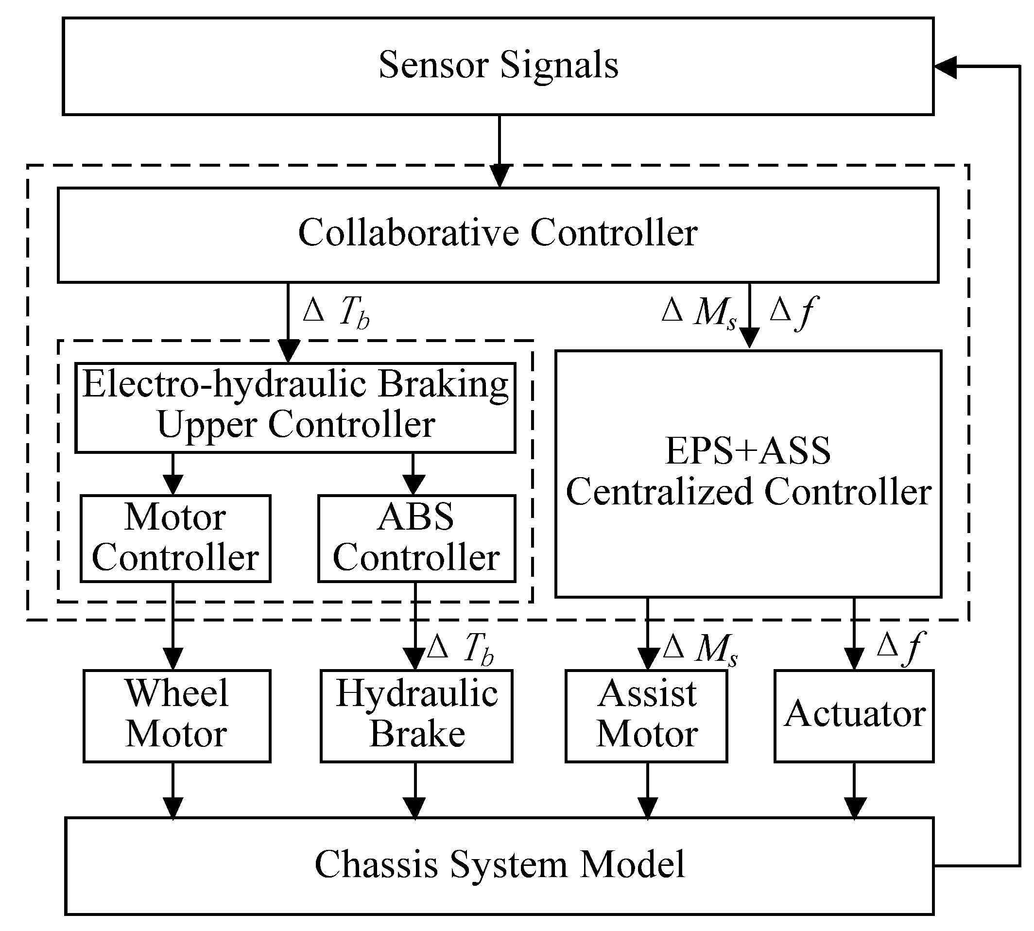
When the three subsystems are coupled to each other, the above two controllers are regarded as the same level and coordinatively controlled by another collaborative controller. The electric vehicle chassis system collaborative control scheme is shown in Figure 3.
Figure 3. Electric vehicle chassis system collaborative control scheme.
Energies 06 00312 g003
The ASS actuator force and tyre vertical load change are calculated by the collaborative controller according to the signals acquired from the electric vehicle chassis system model to realize a trade-off between ride comfort, braking performance and handling stability. As a result, the collaborative controller must coordinate and assign the control force or torque (correction force of the suspension Δf, correction torque of the assist motor ΔMs, compensation braking torque of the front axle ΔTb) to the suspension, steering and braking system.
For the ASS, as the vehicle body pitch motion is caused by braking, the designed correction force of the suspension Δf was used to inhibit the pitch motion and it should follow the brake acceleration change. In the electro-hydraulic braking system, the hydraulic braking torque is proportional to the longitudinal acceleration, so the correction force was designed for the rear suspension as follows:
Δ f i = T b i T b m a x f max   ( i = 3 , 4 )
where Tbmax is the maximum braking torque of the hydraulic brake, fmax is the maximum active suspension force.
For the electro-hydraulic braking system, the front axle load is decreased due to the correction force of the suspension Δf, therefore, the compensation braking torque of the front axle ΔTb was designed as follows:
Δ T b i = Δ F z i r w   ( i = 1 , 2 )
Δ F z i = [ m s Δ a x H + ( l f 2 K s f + l r 2 K s r ) Δ θ ( m u 1 + m u 2 ) Δ u ˙ h f ( m u 3 + m u 4 ) Δ u ˙ h r ] / [ 2 ( l f + l r ) ]   ( i = 1 , 2 )
where, ΔFzi is the front axle load fluctuation, Δ u ˙ is the longitudinal velocity of vehicle centroid fluctuation, hf, hr are the height of the front and rear unsprung mass centroid, respectively, Ksf, Ksr are the stiffness of the front and rear suspensions, respectively.
For the EPS, as the road lateral force coefficient was decreased during cornering braking, the over-steering tendency will be increased according to the original designed assist characteristics, therefore, the correction torque of the assist motor ΔMs was designed as follows:
Δ M s = K k p r s K x G r ( Δ M Z 1 + Δ M Z 2 )
where, ΔMz1, ΔMz2 are the aligning torque of the left front and right front wheels, respectively.

3.3. ASS+EPS Controller Design

The LQG controller which can observe output of ASS and EPS is designed according to the Equations (1)–(4), (6), (7), (10)–(14), and the state vector is constructed as:
X = [ Z 11   Z ˙ 11   Z 12   Z ˙ 12   Z 13   Z ˙ 13   Z 14   Z ˙ 14   Z s   Z ˙ s   θ   θ ˙   φ   φ ˙   v   ω   θ s   θ ˙ s   x r   x ˙ r   θ m   θ ˙ m   i   Z 01   Z 02   Z 03   Z 04 ] T
and the output vector is Y = [ Z ¨ s   θ   φ   ω   v ˙   Z 21 Z 11   Z 22 Z 12   Z 23 Z 13   Z 24 Z 14   T s   θ s ] T , the control input vector is U = [ f 1   f 2   f 3   f 4   U m ] T , the disturbance input vector is U = [ T d ] , the measurement noise vector is ξ = [ ς 1   ς 2   ς 3   ς 4   ς 5   ς 6   ς 7   ς 8   ς 9   ς 10   ς 11 ] T , the model noise vector is W = [ w 1   w 2   w 3   w 4   w 5 ] T . The state space equation of the ASS+EPS systems can be obtained via the simplification as follows:
{ X ˙ = A X + B U + B U + F W Y = C X + ξ
where A is 27 × 27 order system matrix, B is 27×5 order control input matrix, B' is 27 × 1 order interfere input matrix, F is 27 × 5 order model noise input matrix, C is 11 × 27 order output matrix.
In Equation (27), model noise W and measurement noise ξ are zero mean Gaussian white noise and independent signals, their statistical characteristics were:
E { W ( t ) } = E { ξ ( t ) } = E { W ( t ) ξ ( t ) T } = E { ξ ( t ) W ( t ) T } = 0 ,
E { W ( t ) W ( t ) T } = Q 0 ,   E { ξ ( t ) ξ ( t ) T } = R 0 .
where Q0 is model noise covariance matrix, R0 is measurement noise covariance matrix. Kalman filter optimal state estimator can be constructed according to the above system state space equations:
X ^ ˙ = A X ^ + B U + L ( Y C X ^ )
where X ^ is the state estimate, L = P 0 C T R 0 1 is the feedback gain matrix of Kalman filter optimal state estimator, matrix P0 was obtained by the algebraic equation as follows:
A P 0 + P 0 A T + F Q 0 F T P 0 C T R 0 1 C P 0 = 0
The output vectors of ASS+EPS systems should be designed for the control target to make the vehicle have good handling stability, ride comfort and steering portability. It should reduce the vehicle’s vertical acceleration, pitch angle, roll angle, lateral acceleration, yaw rate, suspension travel, steering shaft measured torque and angle, in addition should minimize the control input vector for easy control. Performance index functional was designed based on the above consideration as follows:
J = 1 2 0 [ q 1 Z ¨ s 2 + q 2 θ 2 + q 3 φ 2 + q 4 v ˙ 2 + q 5 ω 2 + q 6 ( Z 21 Z 11 ) 2 + q 7 ( Z 22 Z 12 ) 2 + q 8 ( Z 23 Z 13 ) 2 + q 9 ( Z 24 Z 14 ) 2 + q 10 T s 2 + q 11 θ s 2 + r 1 f 1 2 + r 2 f 2 2 +   r 3 f 3 2 + r 4 f 4 2 + r 5 U m 2 ] d t
where qi are weighting coefficients of corresponding control targets, ri are weighting coefficients of control vectors. The Equation (30) was rewritten in a matrix form as:
J = 1 2 0 [ Y T Q Y + U T R U ] d t
where Q is state weighting matrix, R is control weighting matrix. It can be found by substituting Y = C X to Equation (31):
J = 1 2 0 [ X T Q ^ X + U T R U ] d t
where Q ^ = C T Q C .
According to the optimal control theory, Linear Quadratic Regulator (LQR) optimal control law is U = K X , where K = R 1 B T P is the feedback gain matrix of optimal control law, matrix P was obtained by the algebraic equation as follows:
A T P + P A P B R 1 B T P + Q ^ = 0

3.4. Electro-Hydraulic Braking System Controller Design
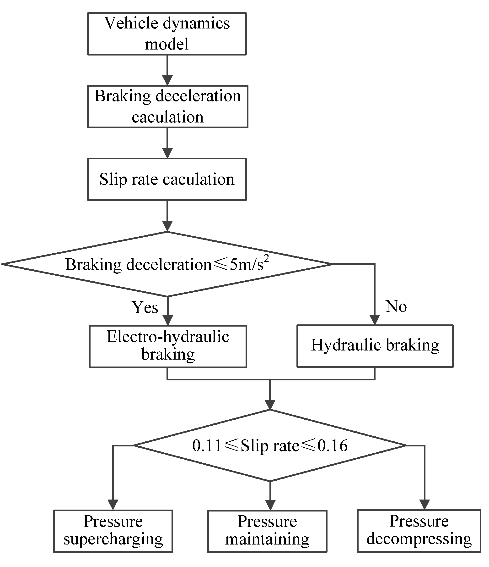
In this paper, the target of the electro-hydraulic braking system controller is designed for guaranteeing the braking performance and safety, therefore, the dominant role of ABS control and the subsidiary role of motor control are played during braking, furthermore, a logic threshold controller based on slip rate is designed for ABS control, taking the slip rate threshold upper limit is 0.16, the lower limit is 0.11, the specific control process is shown in Figure 4.
Figure 4. Electro-hydraulic braking control strategy.
Energies 06 00312 g004

4. Simulation Results and Analysis

The simulation experiments were carried out with collaborative and individual control respectively, and the model parameters are listed in Table 1. The simulation method is as follows: the simulation algorithm is Ode45 and automatically step is adopt, model noise power are 20 dB, measurement noise power are 1 × 10⁻⁵ dB, the input torque of steering shaft is 2 N·m step input and the vehicle initial braking speed is 10 m/s.
After repeatedly debugging, it could achieve a better control effect with the weighting coefficients of ASS+EPS systems as follows: q1 = 100, q2 = 50, q3 = q4 = 80, q5 = 100, q6~q9 = 20, q10 = 80, q11 = 120, r1~r5 = 0.0005, q0i = 10−3, r0i = 10−7. The simulation results are shown in Figure 5, Figure 6, Figure 7, Figure 8, Figure 9 and Figure 10.
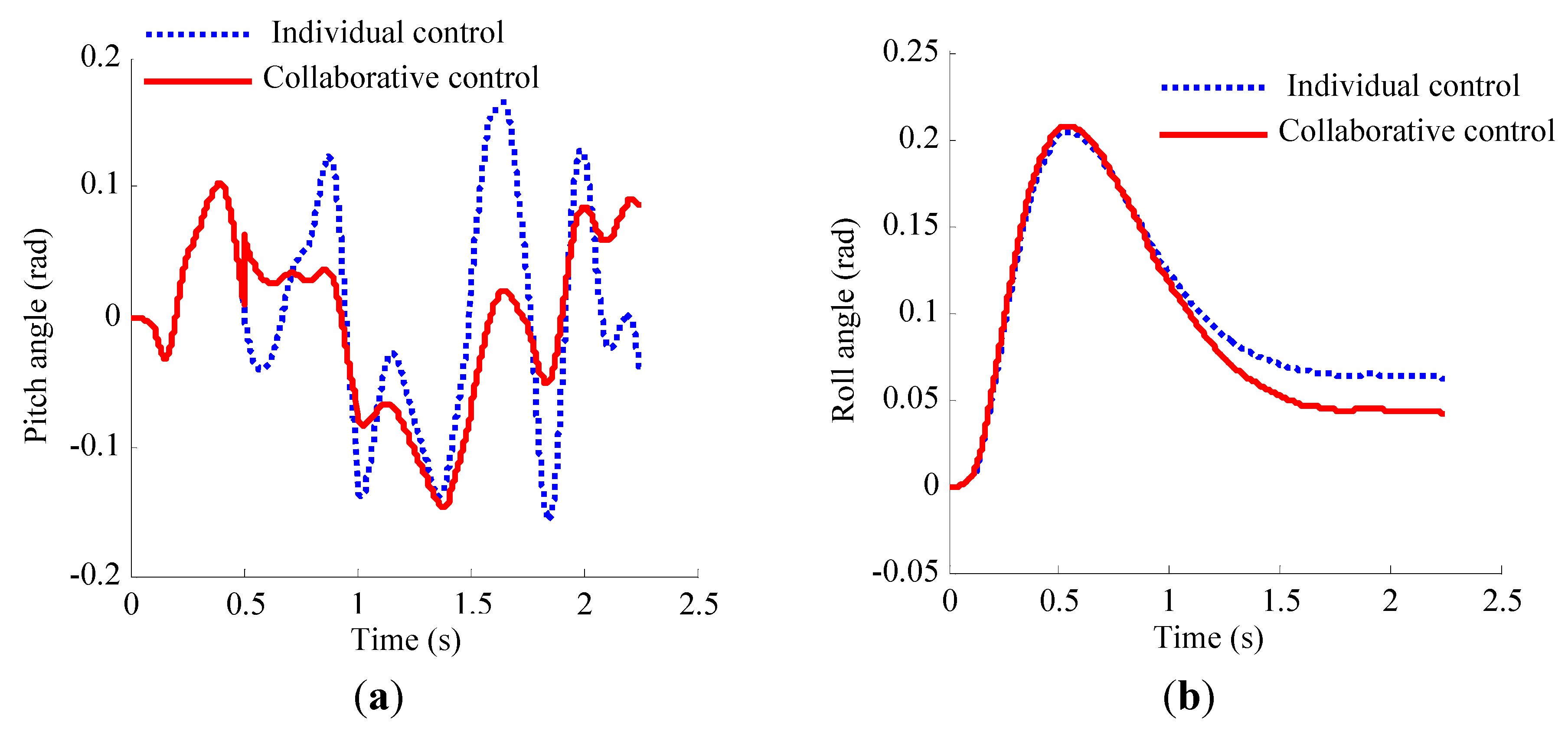
As shown in Figure 5 and Figure 6, with the collaborative control, the pitch angle is obviously improved, which means the correction force of the suspension Δf is effective to inhibit the pitch motion during braking. Although the overshoot of the roll angle is slightly increased, the steady-state value is improved significantly compared with that of individual control. The steady-state values of front wheel corner and yaw rate have different degrees of reduction than that with individual control, which implies that the correction torque of the assist motor ΔMs is effective to inhibit the steering effect during steering, avoid excessive steering and enhance steering stability. In conclusion, the handling stability and steering stability could be effectively improved with the collaborative control.
Table 1. Simulation parameters.
ParametersValuesParametersValues
Bm0.0035 N·m·s/radKa0.5 N·m/A
Bs0.0275N·m·s/radKkp10 N·m/rad
Br0.0275 N·m·s/radKm626 N·m /rad
cs0.1 mKs183 N·m/rad
cf1.100 mKv0.0367 V·s/rad
cr1.585 mKx10,000 N·m/rad
df1.58 mKf0.95 N·m /Pa
dr1.60 mlf1.185 m
f00.01 Hzlr1.500 m
f0.015L0.0000009 H
G00.000005 m3/cycleLm0.008 H
Gm7.5Ls0.00005 H
Gr10mr33 kg
hf0.35 mms1080 kg
hr0.32 mm1350 kg
is15np2
Iw15 kg·m2R0.035 Ω
Izu1598kg·m2Rs0.975 Ω
Iys2444 kg·m2rs0.007 m
Js0.042 kg.m2rw0.303 m
Jm0.00047 kg.m2Tpwm0.0002 s
Cbi1500 N·s/m(1,2), 1300 N·s/m(3,4)Kui200,000 N/m(1,2), 180,000 N/m(3,4)
Ksi17,000 N/m(1,2), 22,000 N/m(3,4)mui40.5 kg(1,2), 45.4 kg (3,4)
Figure 5. Simulation results of vehicle pitch and roll angle: (a) Pitch angle; (b) Roll angle.
Energies 06 00312 g005
Figure 6. Simulation results of vehicle front wheel corner and yaw rate: (a) Front wheel corner; (b) Yaw rate.
Energies 06 00312 g006
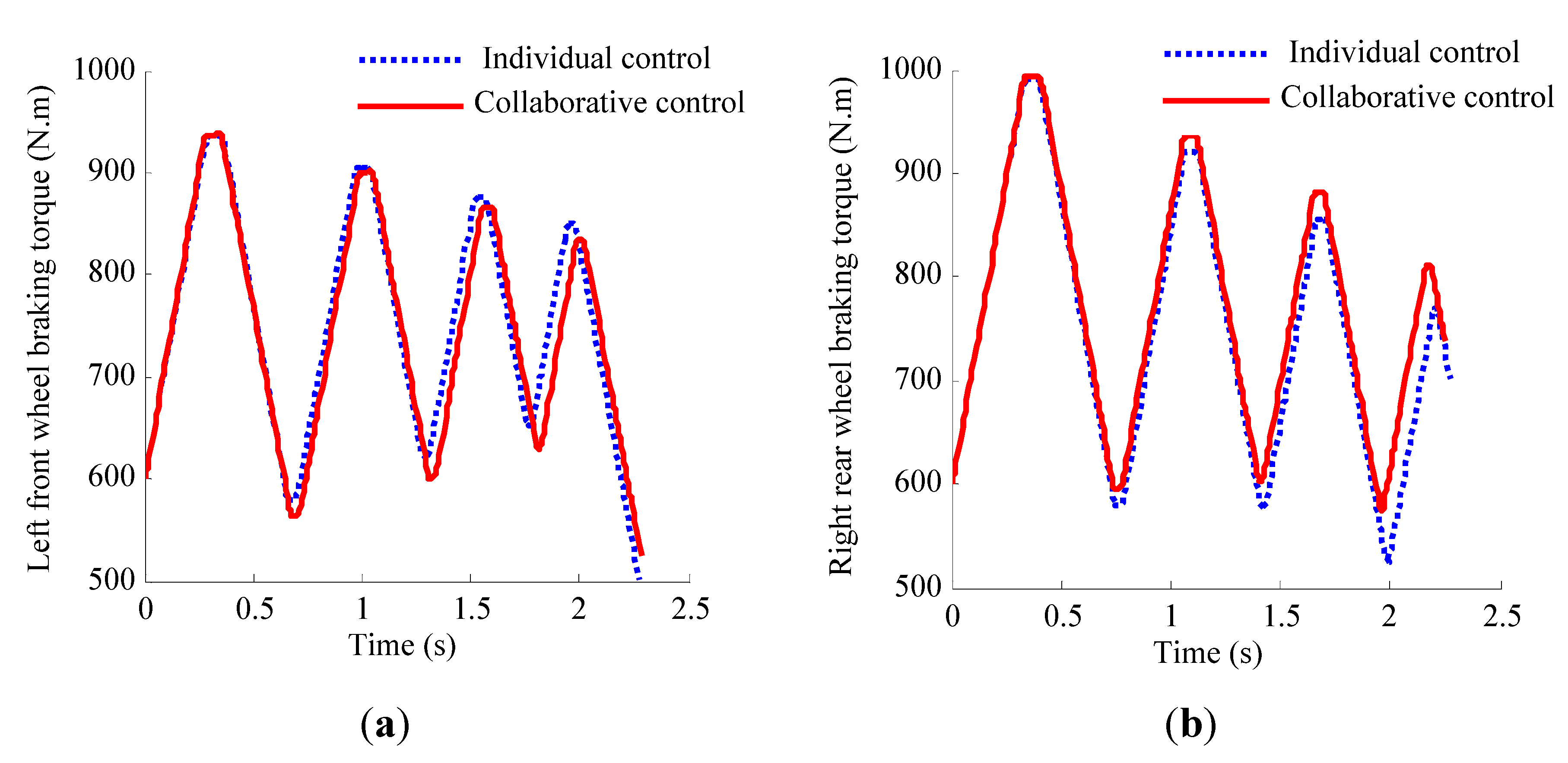
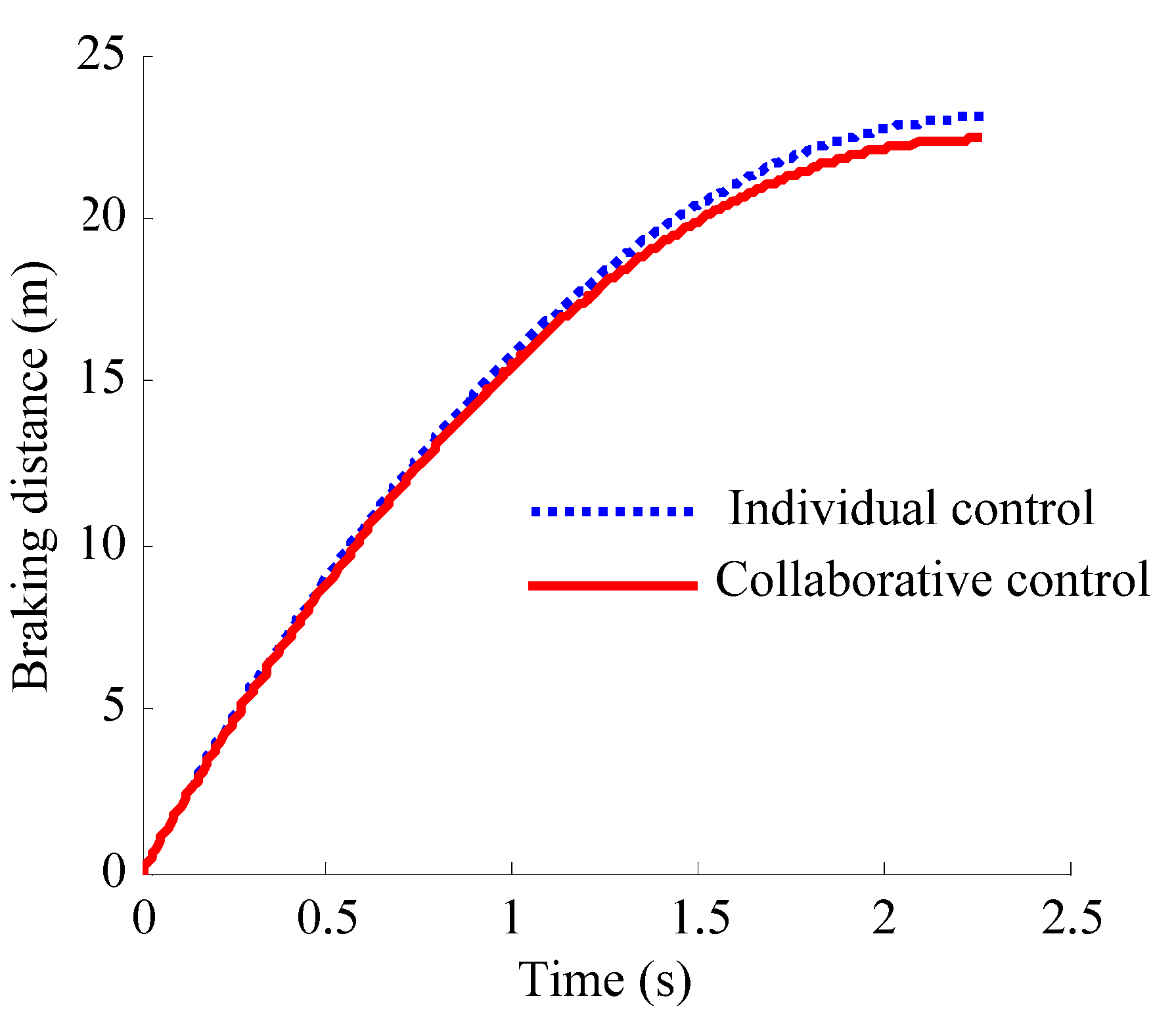
Figure 7 indicates that with the collaborative control, the right rear wheel braking torque is increased compared to that with individual control because the vertical load is transferred from the front axle to rear axle caused by the correction force of the suspension Δf, while after the front axle vertical load is reduced, the front torque has a good following ability due to the compensation braking torque of the front axle ΔTb. As shown in Figure 8, the distance is reduced from 22.5 m to 21.7 m respectively with individual control and collaborative control, which implies that braking performance has been improved. Therefore, it can be seen that the collaborative control could inhibit the problem of longitudinal load transfer between the front axle and the rear axle during braking, which is helpful to make the front wheels and the rear wheels fully use the ground adhesion conditions, and the braking performance will be improved.
Figure 7. Simulation results of vehicle braking torques: (a) Left front wheel braking torque; (b) Right rear wheel braking torque.
Energies 06 00312 g007
Figure 8. Comparison of braking distance.
Energies 06 00312 g008
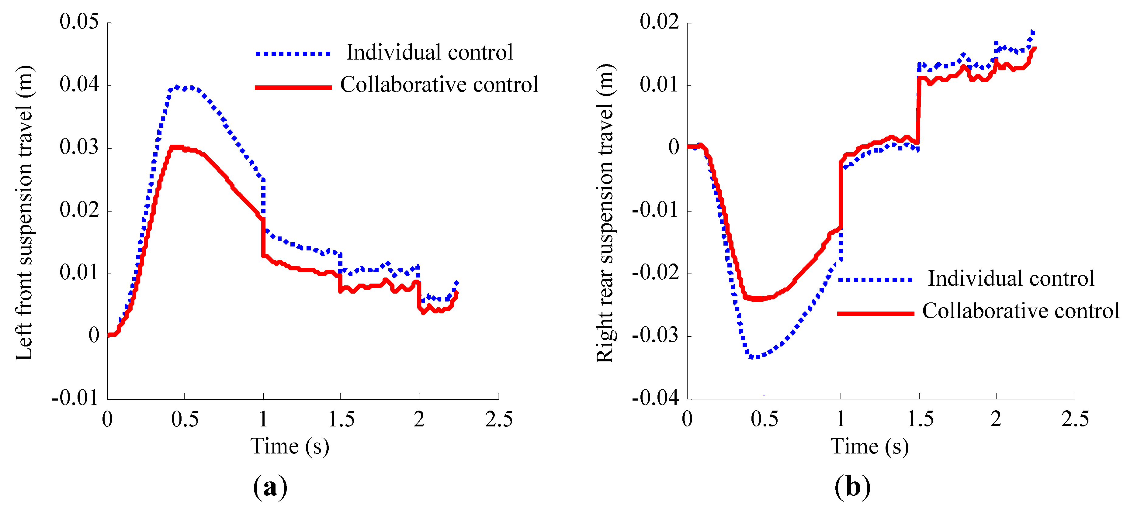
As shown in Figure 9, the results indicate that with the collaborative control, suspension travel response overshoot is obviously decreased, and the amplitude of suspension travel is less than that of with individual control, negative values appear in the steady-state value of the right rear suspension because of we ignored the lateral load transfer for simplification in our collaborative control. The above results imply that the probability of the impact on buffer block is reduced effectively, namely the suspension performance is improved.
Figure 9. Simulation results of vehicle suspension travel: (a) Left front suspension travel; (b) Right rear suspension travel.
Energies 06 00312 g009
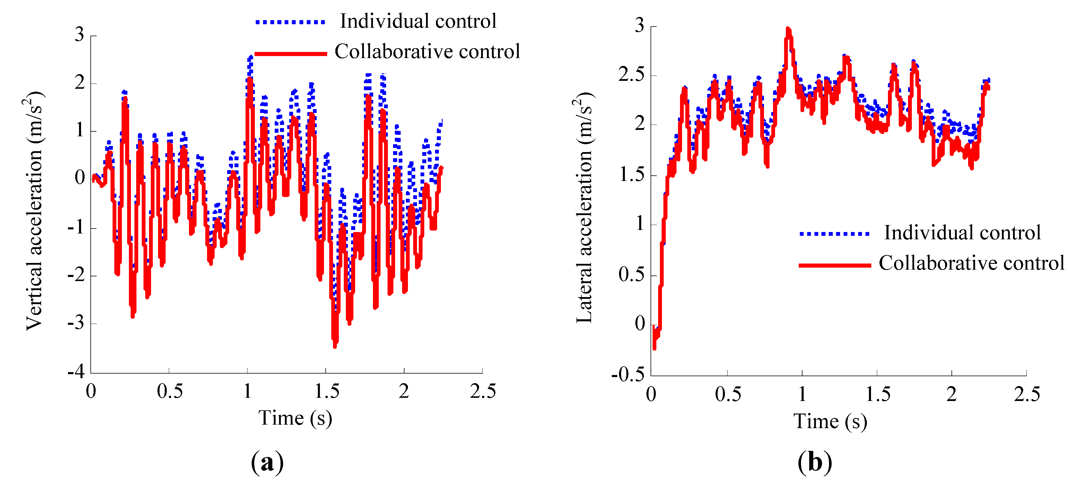
As shown in Figure 10, the results indicate that with the collaborative control, the vertical acceleration and lateral acceleration of the sprung mass are improved to some extent, which means that the collaborative control has a certain effect in improving the ride comfort, in addition, the reduced lateral acceleration is advantageous to improve the lateral stability of vehicle, thereby improving the abilities to maintain tyre steering and to prevent side slip.
Figure 10. Simulation results of vehicle vertical acceleration and lateral acceleration: (a) Vertical acceleration; (b) Lateral acceleration.
Energies 06 00312 g010
A RMS analysis on the vehicle performance parameters is listed in Table 2. It indicates the RMS values of the pitch angle, rear wheel braking torque and yaw rate are changed from 0.0632 rad to 0.0478 rad, from 787.87 N·m to 805.50 N·m and from 0.6192 rad/s to 0.4055 rad/s, respectively, which indicates that the collaborative controller could effectively inhibit the longitudinal load transfer, make full use of ground adhesion and reduce the possibility of excessive steering. In addition, the RMS values of the roll angle and lateral acceleration are respectively reduced from 0.0845 rad to 0.0653 and from 2.3186 rad/s2 to 2.2312 rad/s2, the braking distance is reduced from 22.5 m to 21.7 m, which demonstrates that the collaborative control system could effectively improve the vehicle handling stability and braking safety.
Table 2. A RMS analysis on the vehicle performance parameters.
RMS valueIndividual controlCollaborative control
θ (rad)0.06320.0478
φ (rad)0.08450.0653
δ (rad)12.383210.1294
ω (rad/s)0.61920.4055
T b 1 + T m 1 (N·m)768.83765.26
T b 4 + T m 4 (N·m)787.87805.50
Z 21 Z 11 (m)0.01970.0145
Z 24 Z 14 (m)0.00930.0056
Z ˙ s (rad/s2)0.97320.9657
v ˙ (m/s2)2.31862.2312

5. Conclusions

(1) In this paper, a new control architecture named collaborative control is designed based on the combination of centralized architecture and hierarchical architecture; this architecture is able to respond flexibly to the controllers designed for multi-subsystems in vehicle chassis, and furthermore, the reliability and integrated control of the system can be guaranteed.
(2) The two subcontrollers can optimize and improve the control performance of the subsystems, therefore, the collaborative controller can fulfill the coordination optimization of subsystem by only giving the correction and compensation control orders to the two sub-controllers, which have closely coupled functions. A simulation experiment on the typical cornering braking is performed and the results show that the collaborative control system could effectively improve the vehicle handling stability and braking safety.

Acknowledgements

This work was supported by the National High Technology Research and Development Program of China (2011AA11A228, 2012AA111603, 2011AA11A290) in part, the International Cooperation Research Program of Chinese Ministry of Science and Technology (2011DFB70020) in part, the Program for New Century Excellent Talents in University (NCET-11-0785) in part, the National Natural Science Foundation of China (NSFC: 51075010, 51007003 ) in part, the Key Funding Project of the Beijing Municipal Commission of Education and the Natural Science Funding Project of Beijing (KZ200910005007). The authors would also like to thank the reviewers for their corrections and helpful suggestions.

References

  1. Choi, S.B.; Sung, K.G.; Cho, M.S.; Lee, Y.S. The braking performance of a vehicle anti-lock brake system featuring an electro-rheological valve pressure modulator. Smart Mater. Struct. 2007, 16, 1285–1297. [Google Scholar] [CrossRef]
  2. Dannöhl, C.; Müller, S.; Ulbrich, H. H-control of a rack-assisted electric power steering system. Veh. Syst. Dyn. 2012, 50, 527–544. [Google Scholar] [CrossRef]
  3. Hyniova, K.; Antonin, S.; Jaroslav, H.; Kruczek, A. Active suspension system with linear electric motor. WSEAS Trans. Syst. 2009, 8, 278–287. [Google Scholar]
  4. Lu, S.B.; Li, Y.N.; Choi, S.B.; Zheng, L.; Seong, M.S. Integrated control on MR vehicle suspension system associated with braking and steering control. Veh. Syst. Dyn. 2011, 49, 361–380. [Google Scholar] [CrossRef]
  5. Hac, A.; Bodie, M. Improvements in vehicle handling through integrated control of chassis systems. Int. J. Veh. Auton. Syst. 2002, 1, 83–110. [Google Scholar] [CrossRef]
  6. Gordon, T.; Howell, M.; Brandao, F. Integrated control methodologies for road vehicles. Veh. Syst. Dyn. 2003, 40, 157–190. [Google Scholar] [CrossRef]
  7. Gao, X.J.; Yu, Z.P.; Zhang, L.J. A study on the control architecture of an integrated chassis control system. Automot. Eng. 2007, 29, 21–26. [Google Scholar]
  8. Chen, W.W.; Xiao, H.S.; Liu, L.Q. Integrated control of automotive electrical power steering and active suspension systems based on random sub-optimal control. Int. J. Veh. Des. 2006, 42, 370–391. [Google Scholar] [CrossRef]
  9. Peng, J.K.; Zhang, X.L.; Feng, N.L. Integrated modeling and simulation of electric power steering system. J. Hubei Autom. Ind. Inst. 2011, 25, 19–23. [Google Scholar]
  10. Peng, D. Study on Combined Control of Regenerative Braking and Anti-Lock Braking System for Hybrid Electric Vehicle. Ph.D. Thesis, Shanghai Jiao Tong University, Shanghai, China, 2007. [Google Scholar]
  11. Yang, G.; Luo, Y.L. Electrical Machinery and Motion Control Systems, 1st ed.; Tsinghua University Press: Beijing, China, 2006; pp. 338–356. [Google Scholar]
  12. Wang, H.G.; Xu, W.L.; Yang, G.; Li, J. Variable-structure torque control of induction motors using space vector modulation. Electr. Eng. 2005, 87, 93–102. [Google Scholar] [CrossRef]
  13. Pacejka, H.B.; Bakker, E. The magic formula tyre model. Veh. Syst. Dyn. 1992, 21, 1–18. [Google Scholar] [CrossRef]
  14. Yu, F.; Crolla, D.A. An optimal self-tuning controller for an active suspension. Veh. Syst. Dyn. 1998, 29, 51–65. [Google Scholar] [CrossRef]