Thermal Performance of Motor and Inverter in an Integrated Starter Generator System for a Hybrid Electric Vehicle

Abstract
:1. Introduction

2. Design and Numerical Analysis
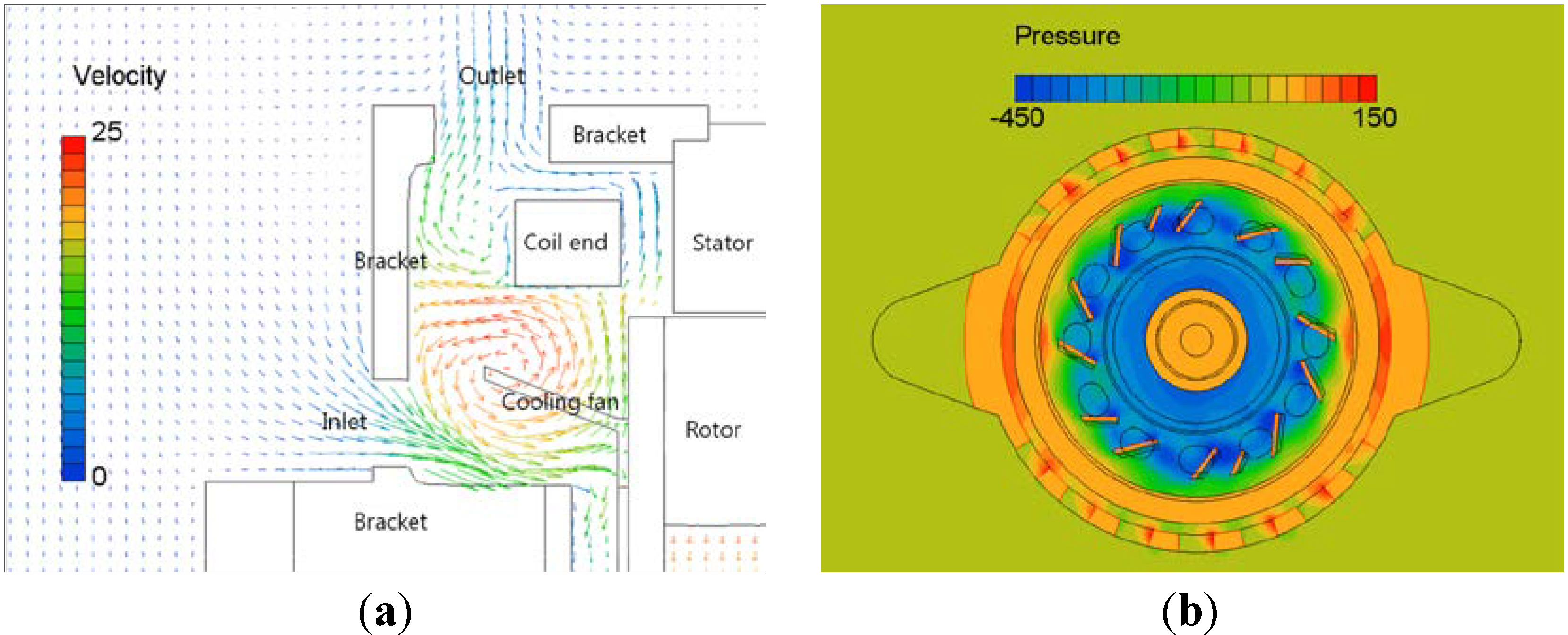
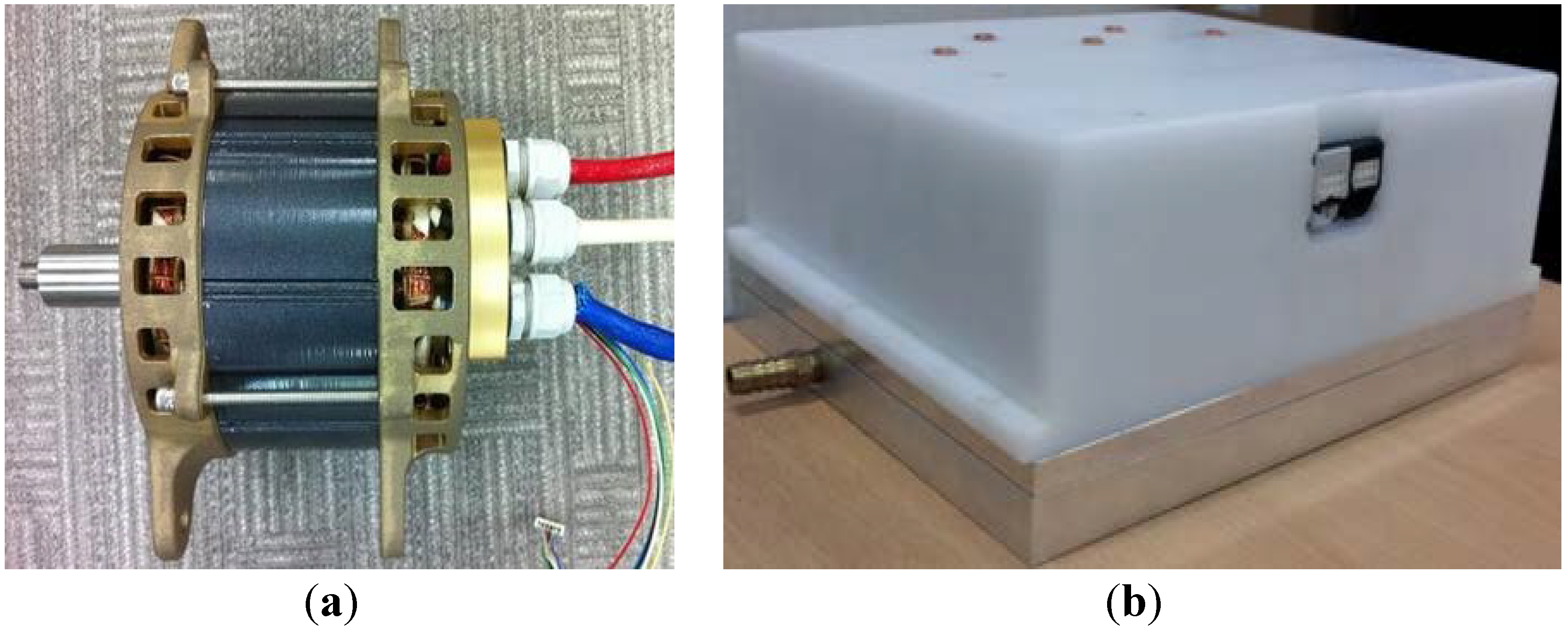
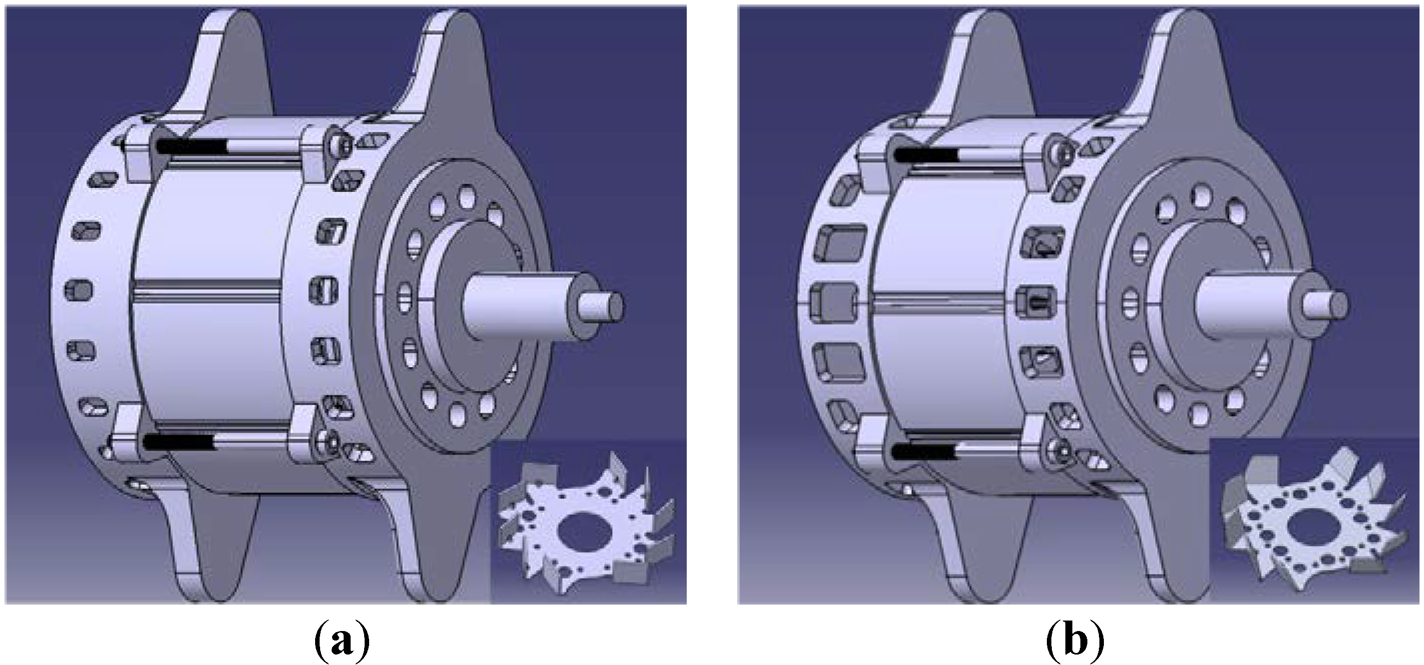
2.1. Air-Cooled Motor


| Items | Components | Conditions |
|---|---|---|
| Ambient temp. (°C) | Motor | 25 *, 95 |
| Ambient pressure (Pa) | 101,325 | |
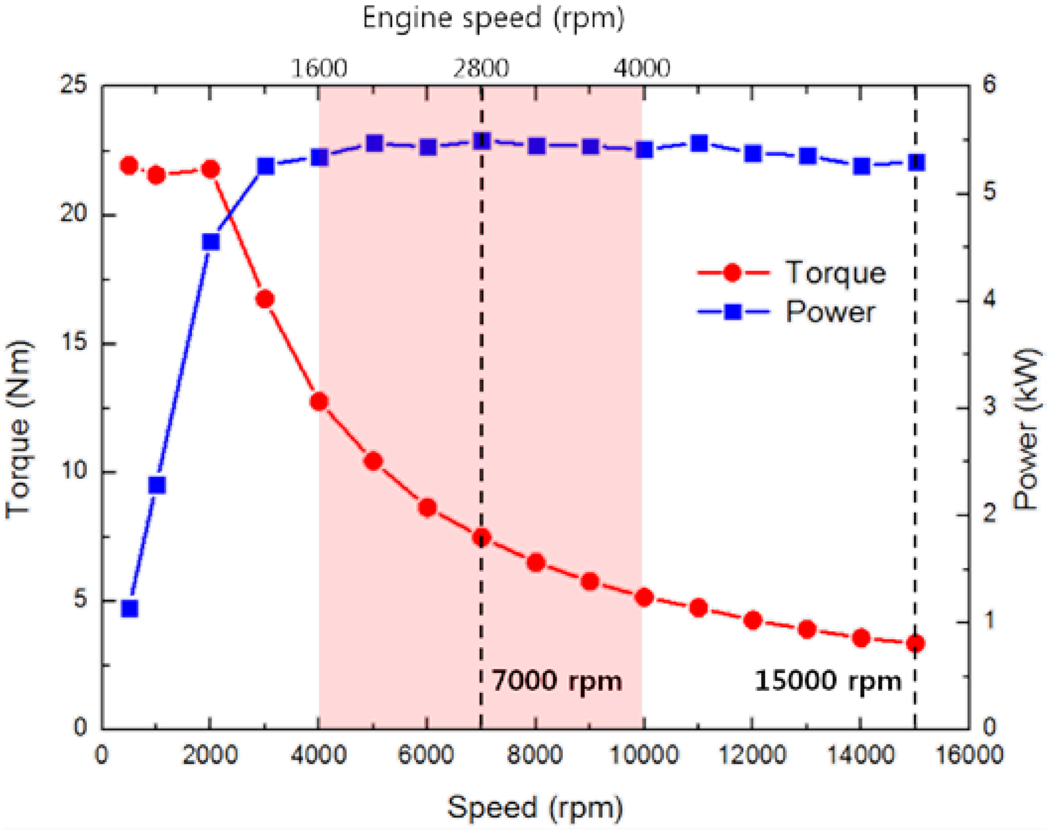
| Motor speed (rpm) | 7000 *, 15,000 | |
| Motor torque (Nm) | 7.5 *, 3.6 | |
| Inverter current (Arms) | Inverter | 150 |
| Coolant flow rate (L/min) | 2, 4 *, 6 | |
| Coolant inlet temp. (°C) | 45, 55, 65 * | |
| Heat source (W) | Coil | 450.6 *, 450.6 (@15,000 rpm), 583.5 (@95 °C) |
| Stator core | 16.4 *, 212.9 (@15,000 rpm), 17.2 (@95 °C) | |
| Bearing | 46.5 *, 145.7 (@15,000 rpm), 46.5 (@95 °C) | |
| MOSFET | 179.7 | |
| Busbar | 5.5 |
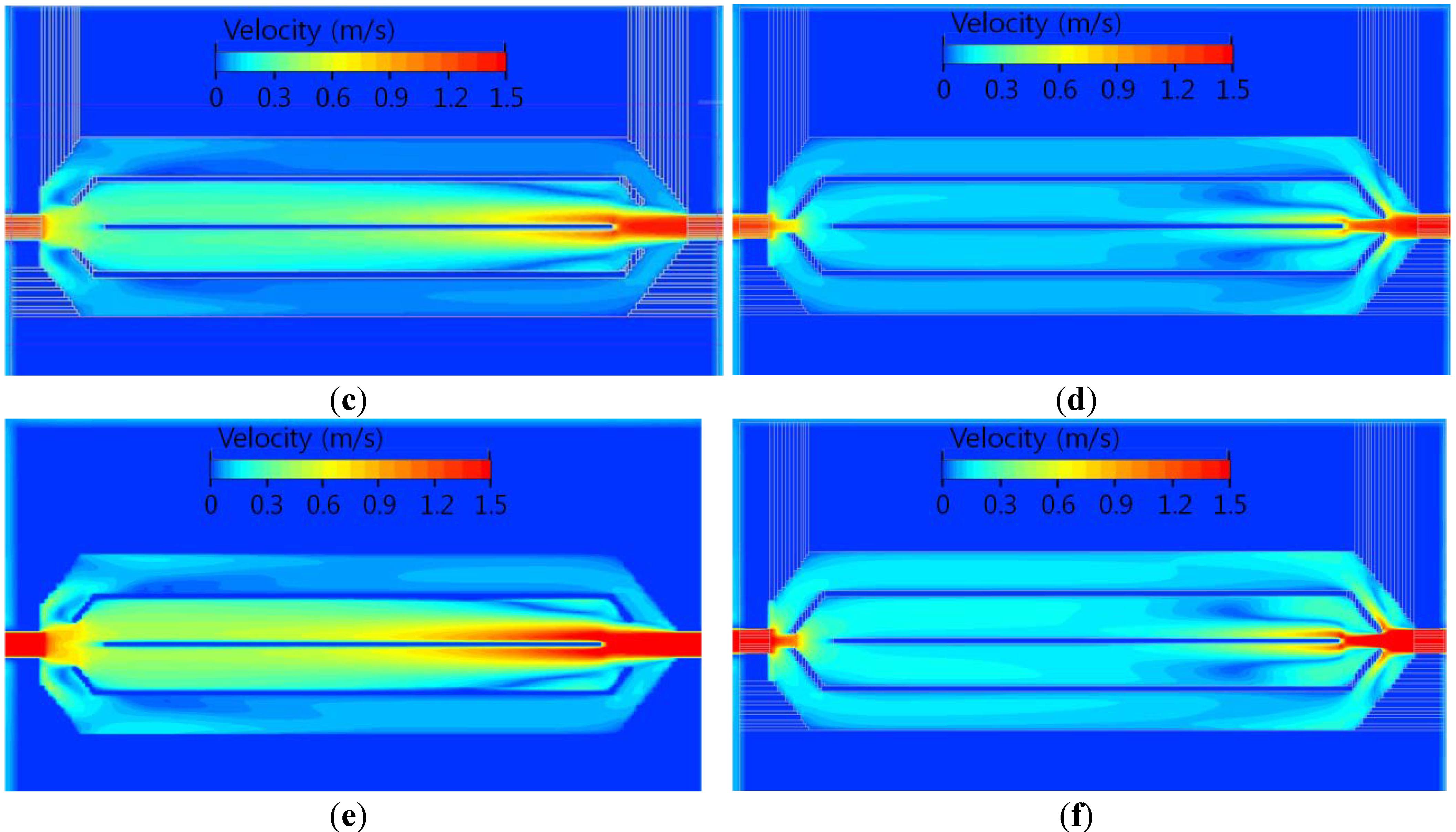
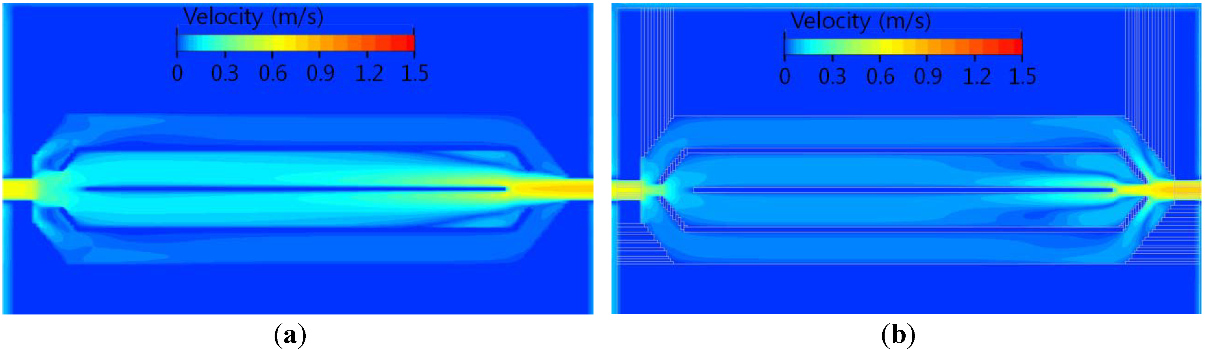
2.2. Liquid-Cooled Inverter
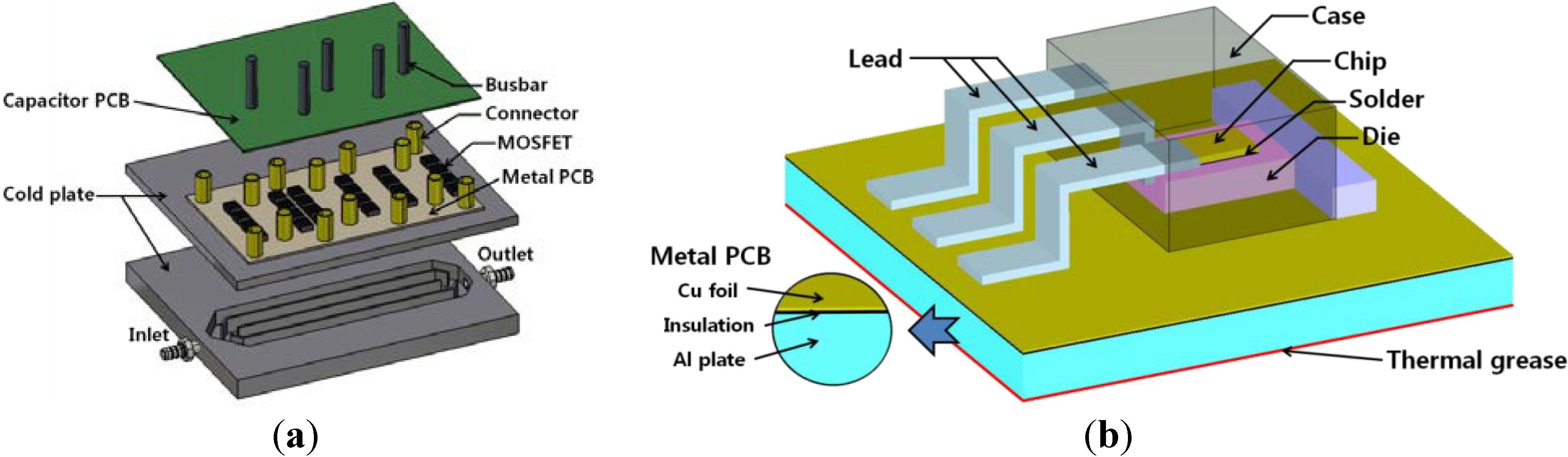
| Part name | No. | Size (mm3) | Density (kg/m3) | Specific heat (J/kg °C) | Thermal conductivity (W/m K) | |
|---|---|---|---|---|---|---|
| MOSFET | Package | 24 | 15.2 × 10.2 × 4.45 | - | - | - |
| Chip | 3.3 × 1.81 × 0.25 | 2330 | 700 | 117 | ||
| Solder | 3.3 × 1.81 × 0.025 | 1450 | 134 | 50 | ||
| Die | 5.3 × 3.81 × 1.27 | 1000 | 1000 | 271 | ||
| Lead | 6.23 × 1.46 × 2.9 | 893 | 130 | 188 | ||
| Case | 9.0 × 10.2 × 4.45 | 2300 | 106 | 0.8 | ||
| Metal PCB | Cu foil | 1 | 197 × 113 × 0.07 | 8930 | 385 | 385 |
| Insulation | 197 × 113 × 0.08 | 1200 | 880 | 0.3 | ||
| Al plate | 197 × 113 × 1.85 | 2700 | 963 | 180 | ||
| Capacitor PCB | 1 | 150 × 200 × 1.6 | 1200 | 880 | 0.3 | |
| Busbar | 5 | 4 × 4 × 52 | 8930 | 385 | 385 | |
| Connector | 14 | 6 × 6 × 22 | 8930 | 385 | 385 | |
| Thermal grease | 1 | 197 × 113 × 0.05 | 2490 | 800 | 3.8 | |
| Cold plate | 1 | 236 × 200 × 8 | 2700 | 963 | 180 | |
| Inverter cover | 1 | 220 × 200 × 82 | 1200 | 420 | 0.25 | |

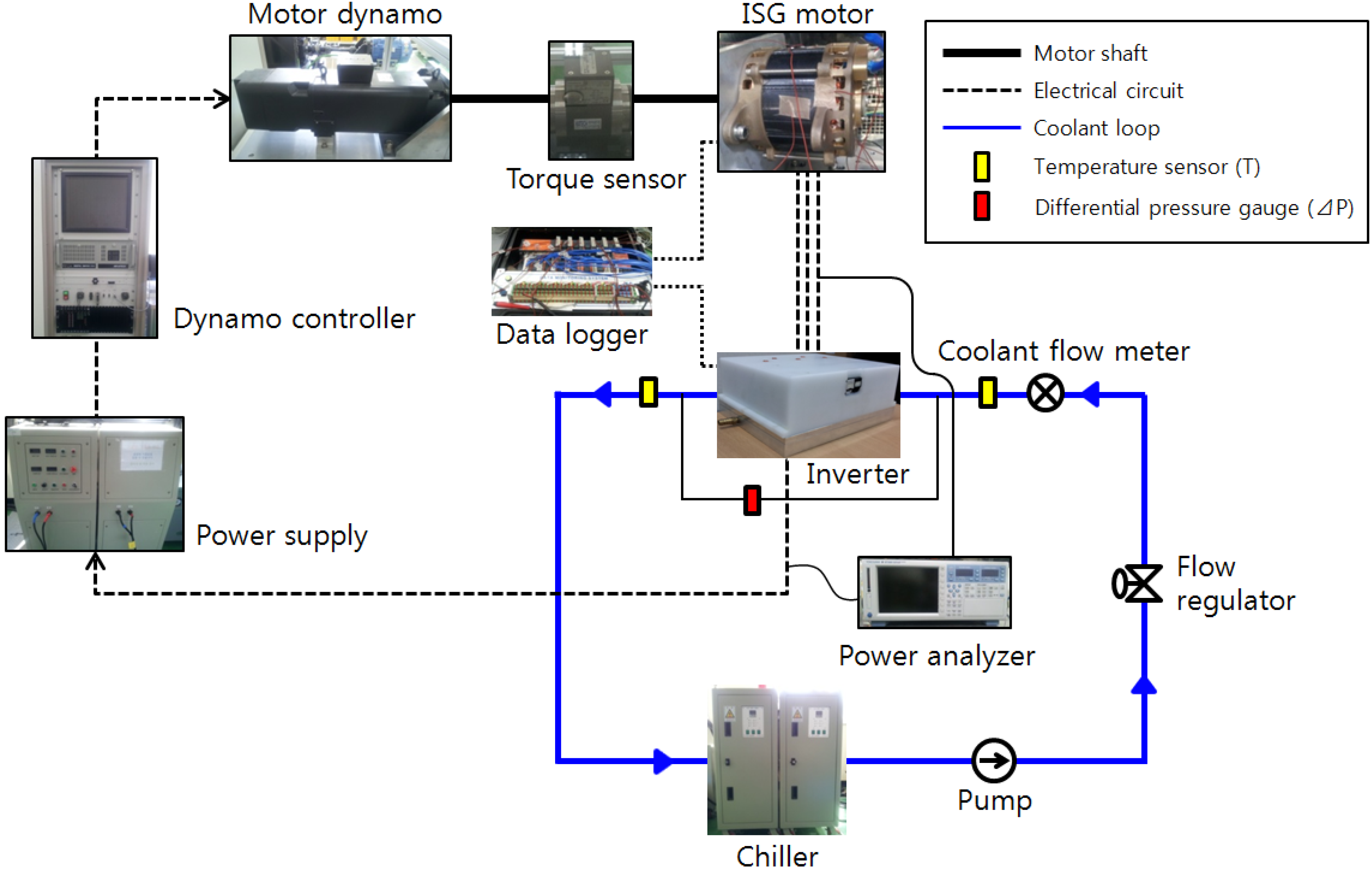
3. Experimental Setup and Data Reduction

| Components | Model | Specifications |
|---|---|---|
| Thermocouples | T-type | −200~400 °C (±0.1 °C) |
| Differential pressure gauge | Honeywell, Morristown, NJ, USA | 33 kPa (±0.01%) |
| Coolant flow meter | Coriolis-type | 10 L/min (±0.1%) |
| Data logger | Gantner, Darmstadt, Germany | E. Gate IP (V3) (2.93 W @12.06 V) |
| Motor dynamometer | Siemens, Berlin, Germany | 60 kW/9,000 rpm/600 Nm |
| Torque transducer | Hottinger Baldwin Messtechnik, Darmstadt, Germany | 20 Nm (±0.1%) |
| Motor speed sensor | Hottinger Baldwin Messtechnik | 12,000 rpm (±0.01%) |
| Power analyzer | Yokogawa, Tokyo, Japan | 15~1,000 V (±0.02%) |
4. Results and Discussion
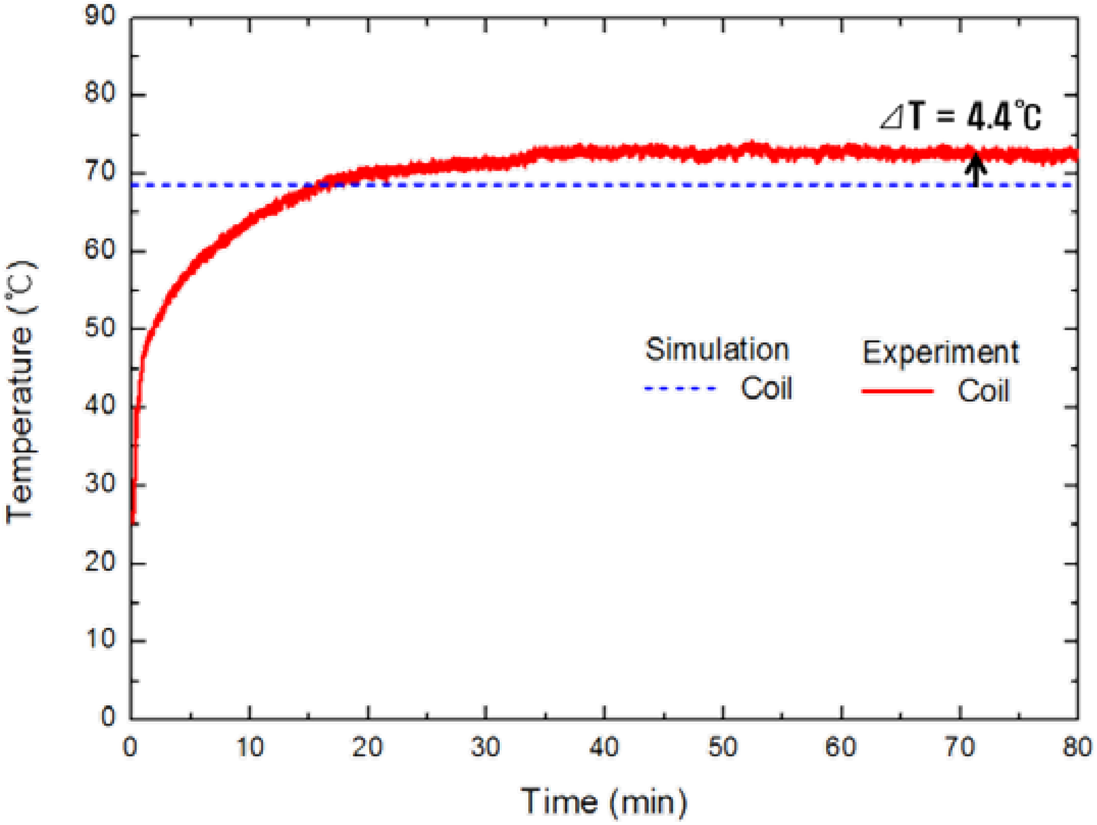
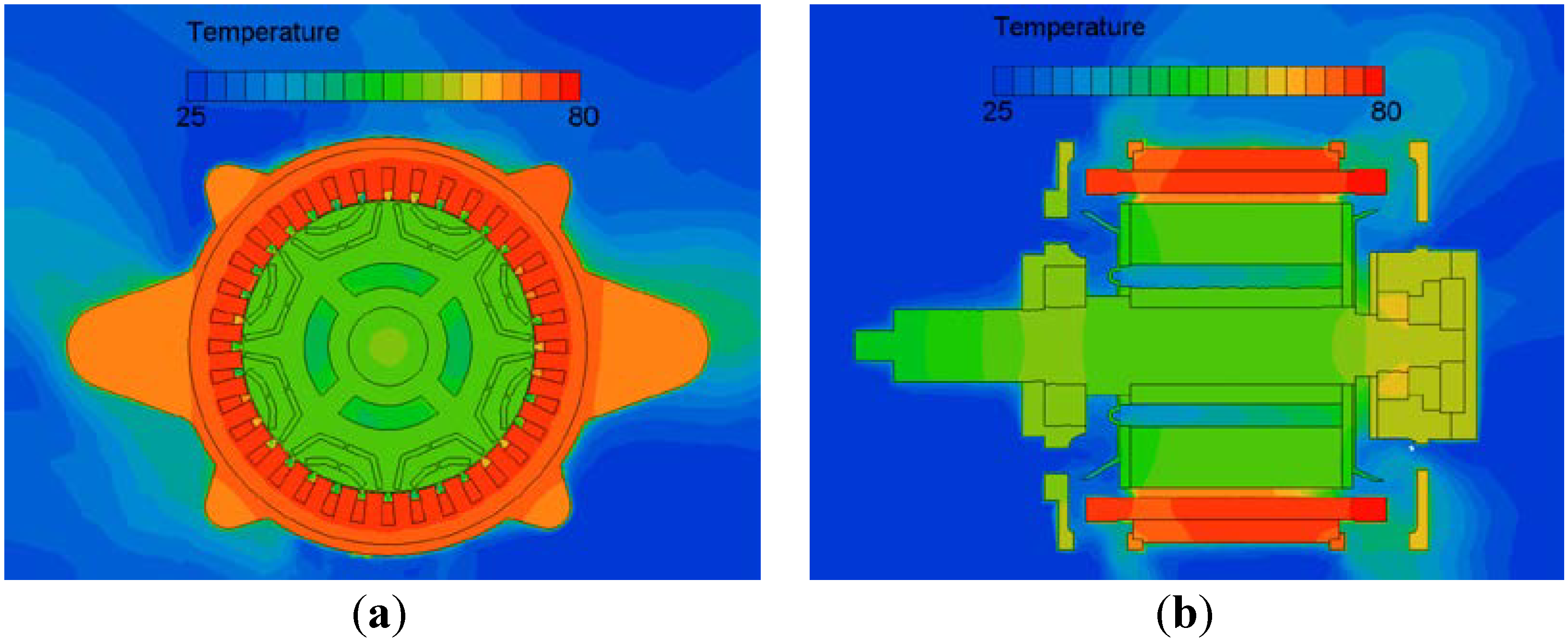
4.1. Thermal Characteristics of the Motor
| Motor part | Vol. temp. (°C) | ||
|---|---|---|---|
| @25 °C, 7,000 rpm | @25 °C, 15,000 rpm | @95 °C, 7,000 rpm | |
| Flange | 63.5 | 60.4 | 142.7 |
| Stator core | 74.6 | 73.4 | 156.7 |
| Coil | 76.1 | 73.1 | 158.5 |
| Front bearing | 59.5 | 59.2 | 137.1 |
| Rear bearing | 63.7 | 67.5 | 140.2 |
| Rotor core | 56.5 | 53.7 | 133.4 |
| Shaft | 56.8 | 55.2 | 133.5 |
| Magnet | 56.7 | 53.9 | 133.7 |
| Bracket | 67.2 | 65.2 | 145.9 |
| Surface regions | Heat flux (W/m2) | ||
|---|---|---|---|
| @25 °C, 7,000 rpm | @25 °C, 15,000 rpm | @95 °C, 7,000 rpm | |
| Air vs. flange | 1,498 | 2,338 | 1,845 |
| Air vs. stator core | 1,609 | 2,397 | 2,059 |
| Air vs. coil | 2,344 | 3,834 | 3,028 |
| Air vs. shaft | 1,216 | 1,747 | 1,502 |
| Air vs. bracket | 1,149 | 1,916 | 1,502 |
| Air vs. rotor core | −1,069 | −1,308 | −1,386 |
| Coil vs. stator core | −5,027 | −3,815 | −6,548 |
| Stator core vs. flange | −28,152 | −34,768 | −35,879 |
| Stator core vs. bracket | −20,438 | −26,046 | −27,563 |


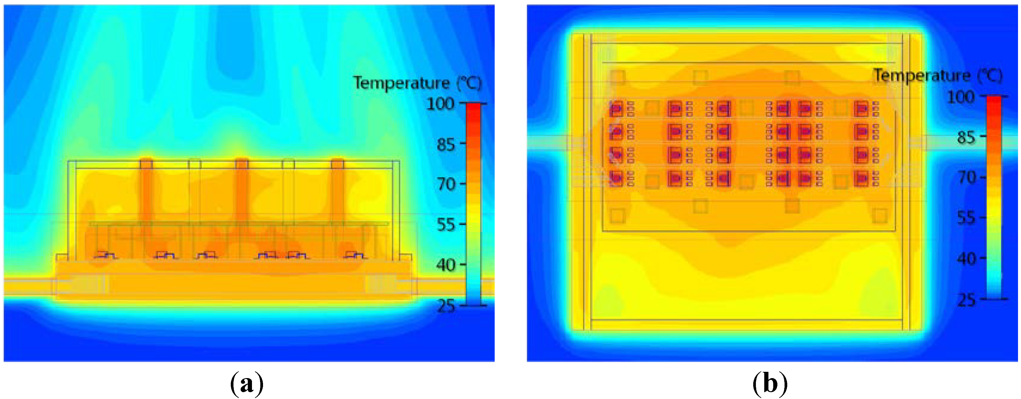
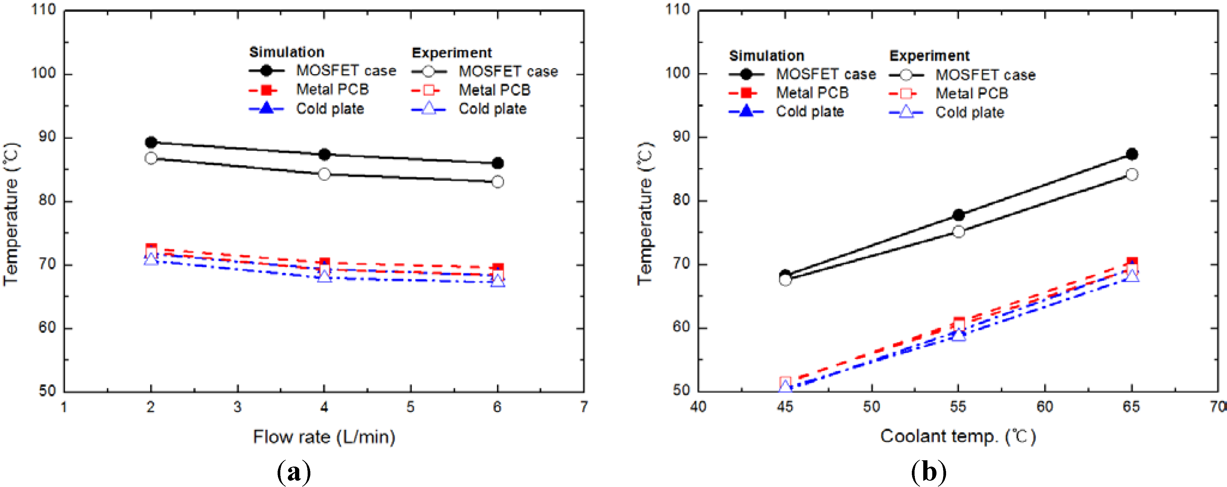
4.2. Thermal Characteristics of the Inverter

| Inverter part | Components | Vol. temp. (°C) @65 °C, 4 L/min |
|---|---|---|
| MOSFET | Chip | 96.8 |
| Case | 87.0 | |
| Metal PCB | - | 70.2 |
| Cold plate | - | 68.6 |

5. Conclusions
Acknowledgments
Conflicts of Interest
Nomenclature
| B | magnetic flux density (T) |
| ƒ | frequency (Hz) |
| I | phase current (Arms) |
| Ion | on-current at metal-oxide-semiconductor field-effect transistor (MOSFET) (Arms) |
| ke | eddy current coefficient |
| kh | hysteresis coefficient |
| L | length of busbar (m) |
| Pbusbar | conduction loss at busbar (W) |
| Pcopper | copper loss at coil (W) |
| Piron | iron loss at core (W) |
| Pe | eddy current loss (W) |
| Ph | hysteresis loss (W) |
| Pswitch | switching loss at MOSFET (W) |
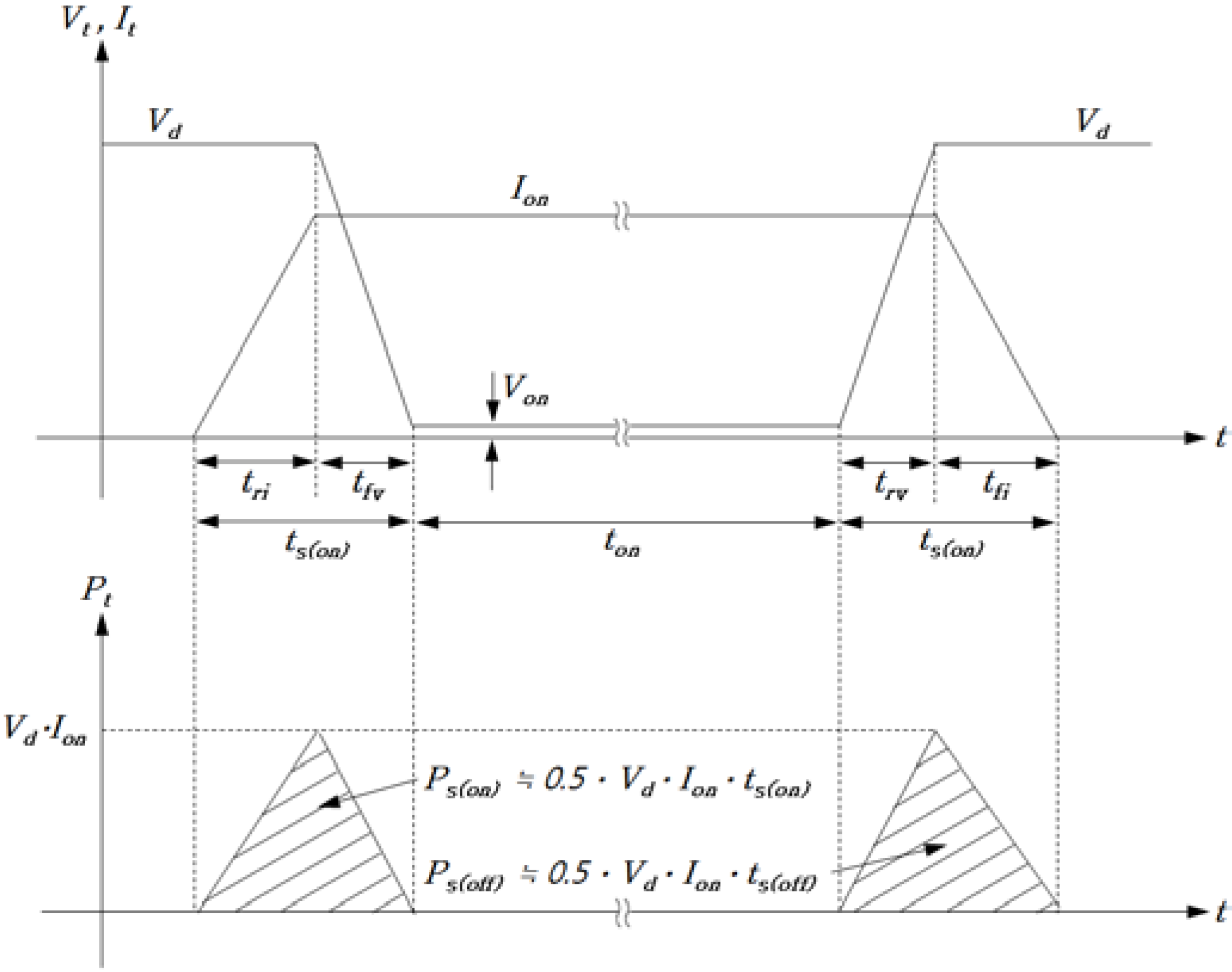
| Ps(on) | switching loss at rising time (W) |
| Ps(off) | switching loss at falling time (W) |
| Pt(on) | conduction loss at MOSFET (W) |
| Rbusbar | busbar resistance (Ω) |
| Rcoil | coil resistance (Ω) |
| S | cross sectional of busbar (m2) |
| Tfric | friction torque (Nm) |
| ts(on) | turn on time of MOSFET (s) |
| tri | current rising time (s) |
| tfv | voltage falling time (s) |
| ts(off) | turn off time of MOSFET (s) |
| tfi | current falling time (s) |
| trv | voltage rising time (s) |
| ton | conduction time of MOSFET per pulse (s) |
| Voff | off time voltage (V) |
| Von | on time voltage (V) |
| ρ | specific resistance (Ω m) |
| ω | angular frequency (rad/s) |
Abbreviations
| CFD | computational fluid dynamics |
| FEA | finite element analysis |
| HEV | hybrid electric vehicle |
| IGBT | insulated gate bipolar transistor |
| ISG | integrated starter generator |
| MOSFET | metal-oxide-semiconductor field-effect transistor |
| MRF | multiple reference frame |
| PCB | printed circuit board |
References
- Yang, F.; Gao, G.; Ouyang, M.; Chen, L.; Yang, Y. Research on a diesel HCCI engine assisted by an ISG motor. Appl. Energy 2013, 101, 718–729. [Google Scholar] [CrossRef]
- Bitsche, O.; Gutmann, G. Systems for hybrid cars. J. Power Sources 2004, 127, 8–15. [Google Scholar] [CrossRef]
- Simopoulos, G.N.; MacBain, J.A.; Schneider, E.D.; Wingeier, E.W. Fuel Economy Improvements in an SUV Equipped with an Integrated Starter Generator. In Proceedings of the SAE International Truck & Bus Meeting & Exhibition, Chicago, IL, USA, 12–14 November 2001.
- Lee, G.; Choi, G.; Choi, W. Design considerations for low voltage claw pole type integrated starter generator (ISG) systems. J. Power Electron. 2011, 11, 527–532. [Google Scholar] [CrossRef]
- Xue, Y.; Ronning, J. Design and testing of a belt-driven induction starter-generator. IEEE Trans. Ind. Appl. 2002, 38, 1525–1533. [Google Scholar] [CrossRef]
- Kimotho, J.; Hwang, P. Thermal management of electric vehicle BLDC motor. SAE Tech. Pap. 2011. [Google Scholar] [CrossRef]
- Li, H.M. Flow driven by a stamped metal cooling fan—Parametric study on blade angles. Eng. Appl. Comput. Fluid Mech. 2010, 4, 222–236. [Google Scholar]
- Mallik, S.; Ekere, N.; Best, C.; Bhatti, R. Investigation of thermal management materials for automotive electronic control units. Appl. Therm. Eng. 2011, 31, 355–362. [Google Scholar] [CrossRef]
- Bennion, K.; Kelly, K. Rapid Modeling of Power Electronics Thermal Management Technologies. In Proceedings of the IEEE Vehicle Power and Propulsion Conference (VPPC), Dearborn, MI, USA, 7–10 September 2009; pp. 622–629.
- Chen, K.; Ahmed, S.; Maly, D.; Parkhill, S.; Flett, F. Comparison of Thermal Performance of Different Power Electronics Stack Constructions. In Proceedings of the SAE Future Car Congress, Arlington, VA, USA, 3–5 June 2002.
- Tamai, G.; Jeffers, M.; Lo, C.; Thurston, C.; Tarnowshy, S.; Poulos, S. Development of the Hybrid System for the Saturn VUE Hybrid. In Proceedings of the SAE World Congress & Exhibition, Detroit, MI, USA, 3–6 April 2006.
- SC/Tetra Version 7 User’s Guide Solver Reference; Software Cradle Co., Ltd.: Osaka, Japan, 2007.
- MotorPro Version 2.6.B User’s Guide Solver Reference; Komotek: Sungnam, Korea, 2004.
- Alshamani, K. Equations for Physical Properties of Automotive Coolants. In Proceedings of the SAE World Congress & Exhibition, Detroit, MI, USA, 3–6 March 2003.
- FloTHERM Version 9.3 Introductory Training for V9, Mentor Graphics Corporation: Wilsonville, OR, USA, 2012.
- Boukhanouf, R.; Haddad, A. A CFD analysis of an electronics cooling enclosure for application in telecommunication systems. Appl. Therm. Eng. 2010, 30, 2426–2434. [Google Scholar] [CrossRef]
- Maniktala, S. Switching Power Supplies A to Z; Elsevier Inc.: Waltham, MA, USA, 2006. [Google Scholar]
- Kim, D.G.; Kim, S.C. An analysis study for thermal design of ISG (integrated starter generator) for hybrid electric vehicle. Trans. Korean Soc. Automot. Eng. 2013, 21, 120–127. [Google Scholar] [CrossRef]
- Zhang, Y.P.; Yu, X.L.; Feng, Q.K.; Zhang, R.T. Thermal performance study of integrated cold plate with power module. Appl. Therm. Eng. 2009, 29, 3568–3573. [Google Scholar] [CrossRef]
© 2013 by the authors; licensee MDPI, Basel, Switzerland. This article is an open access article distributed under the terms and conditions of the Creative Commons Attribution license (http://creativecommons.org/licenses/by/3.0/).
Share and Cite
Kim, S.C. Thermal Performance of Motor and Inverter in an Integrated Starter Generator System for a Hybrid Electric Vehicle. Energies 2013, 6, 6102-6119. https://doi.org/10.3390/en6116102
Kim SC. Thermal Performance of Motor and Inverter in an Integrated Starter Generator System for a Hybrid Electric Vehicle. Energies. 2013; 6(11):6102-6119. https://doi.org/10.3390/en6116102
Chicago/Turabian StyleKim, Sung Chul. 2013. "Thermal Performance of Motor and Inverter in an Integrated Starter Generator System for a Hybrid Electric Vehicle" Energies 6, no. 11: 6102-6119. https://doi.org/10.3390/en6116102