Article

AC Power Local Network with Multiple Power Routers

Department of Electrical Engineering, Kyoto University, Katsura, Nishikyo, Kyoto 615-8510, Japan
*
Author to whom correspondence should be addressed.
Energies 2013, 6(12), 6293-6303; https://doi.org/10.3390/en6126293
Submission received: 26 September 2013 / Revised: 5 November 2013 / Accepted: 25 November 2013 / Published: 2 December 2013
(This article belongs to the Special Issue Smart Grids: The Electrical Power Network and Communication System)

Abstract

:
Controlling power flow and achieving appropriate matching between power sources and loads according to the quality of energy is expected to be one of the approaches to reduce wasted energy consumption. A power router, proposed recently, has the capability of realizing circuit switching in a power distribution network. This study focuses on the feasibility of an AC power routing network system composed of multiple power routers. To evaluate the feasibility, we experimentally confirm the circuit switching operation of the parallel and series configurations of the power routers, so that the network system can be designed by the combination of parallel and series configurations.

1. Introduction

Today, many types of distributed renewable sources, such as photovoltaic generation and wind power generation, have been installed in homes and communities. These sources lack the ability to supply power constantly because of the variability of the sources. For example, output from a photovoltaic system is strongly affected by weather conditions that cause fluctuations in frequency and voltage. In 1998, Toyoda et al. proposed the concept of an open-electric-energy-network (OEEN) where power flow is controlled by multiple electric-energy-routers [1]. This power routing makes it possible for many types of dispersed power sources to participate in an electrical power market without disadvantages to existing power utilities and consumers. Unfortunately, the proposal was made too early to realize the system in those days. Conversely, electrical equipments that have built-in batteries, such as a mobile computer, does not always require high-quality input power. Therefore, more effective power consumption is expected by achieving appropriate source-and-load matching according to the ancillary quality of energy, such as frequency variation and voltage fluctuation [2]. In a conventional AC power distribution system, however, electricity from different power sources cannot be exactly separated in the same distribution line. In order to design a system that has the capability of achieving appropriate matching between sources and loads from a viewpoint of the quality of energy, a path control of power flow on the power distribution network has been investigated as a power routing system that prevents the mixing of powers from different power sources [3,4,5,6]. This type of system is able to realize the concept of OEEN [1]. To establish the power routing system, our group developed a DC power packet dispatching system and an AC power router by applying highly developed power devices and information and communications technologies [5,6,7,8,9,10]. The former is intended to realize a packet transfer in a network for electrical power distribution [5,6,7,8,9]. The latter is intended to realize a circuit matrix for establishing a power distribution circuit [5,6,10]. Power routing methods have been presented and developed by several groups independently. Stalling et al. have designed a universal power router [11], and He et al. have proposed an electric power system with intelligent power switches based on the Internet and microgrids [12]. Conversely, in the cloud computing context, energy dispatched as a pulse, called an energy packet, is also proposed as a method to provide energy on demand to cloud computing servers [13,14,15].
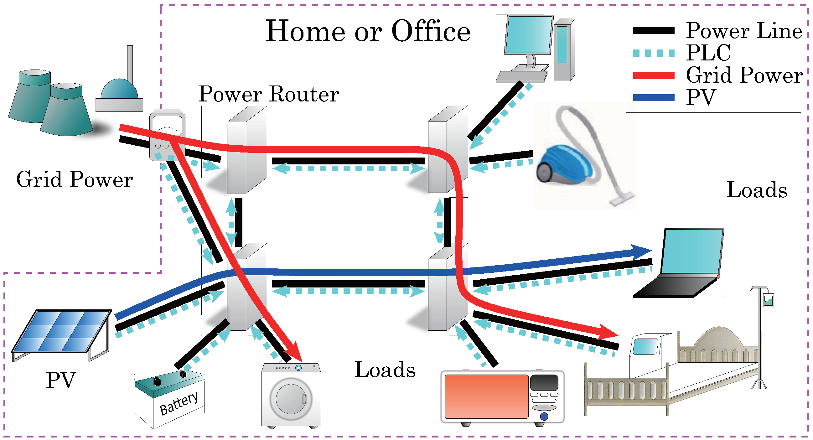
In this study, the feasibility of an AC power routing network system consisting of multiple power routers is preliminarily investigated. Figure 1 shows a schematic diagram of the proposed AC power routing system. We have already developed the hardware for the power router that is able to achieve AC power routing by circuit exchanges [6,10]. The details of the power router are explained in the following section. To evaluate the feasibility of the power routing network system, operations of power routers are experimentally verified in two configurations, i.e., parallel and series configurations. This is because any general network configuration can be classified into parallel and series connections. Simultaneously, we also verify the function of exchanging power lines (PLs) without the restriction of synchronization. This considers a case such as when the power conditioner for a photovoltaic source is driven independently of a commercial power network.
Figure 1. Configuration of an AC power routing system. PLC: power line communication.
Energies 06 06293 g001
This paper is organized as follows. In Section 2, a configuration of the AC power routing system and its functions are explained. In Section 3, the operation of the single AC power router is verified. Section 4 and Section 5 discuss the experimental results of the operations of the power routers in parallel and series connections, respectively. Finally, a conclusion and further discussion are provided in Section 6.

2. AC Power Router and Its Network System
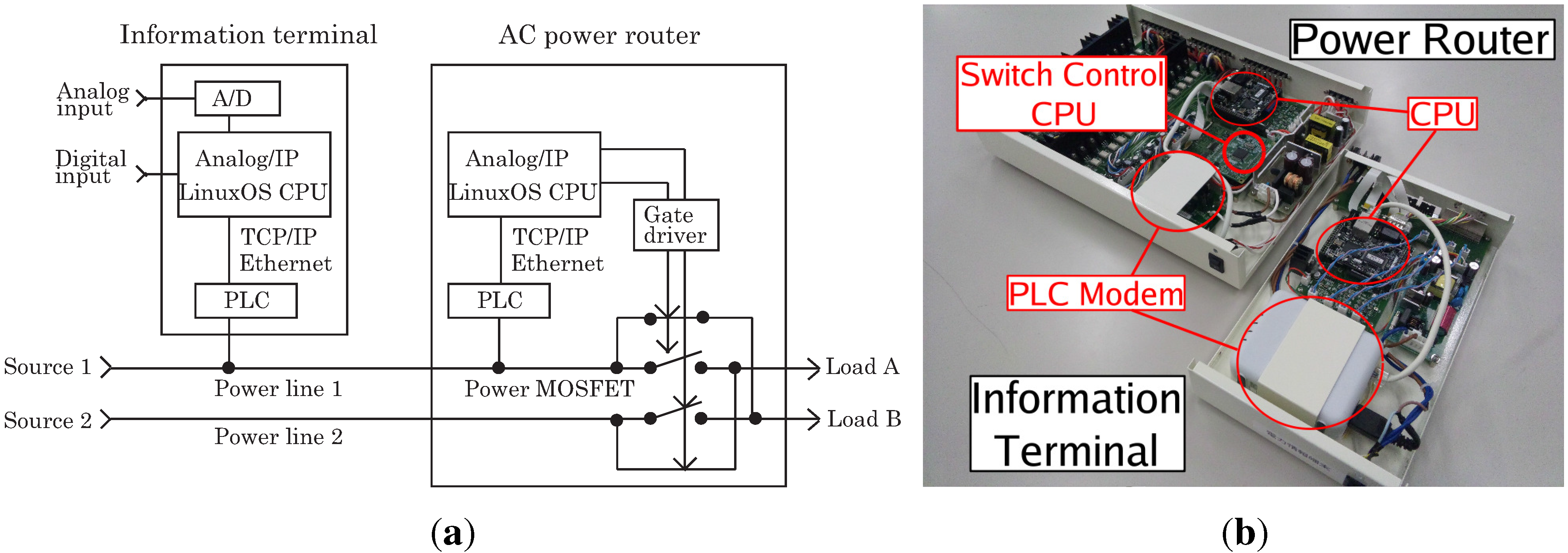
An AC power routing network system can be established by connecting AC power routers and information terminals. Figure 2(a) shows a setup of an AC power router and an information terminal, and Figure 2(b) shows a photograph of the prototype AC power router and the information terminal [6,10]. Each component includes a power line communication (PLC) modem and microprocessor CPU with Linux OS. By using the PLC modem, these components communicate with each other by a connected common PL. The function of the power router is to facilitate the exchange of PLs, i.e., circuit switching. The information terminal plays the role of the controller for power routers, and communicates with power routers to share information related to power capacity, the quality of each source and the demands from loads. The ratings of the prototype power router are set at 100–200 V rms , a continuous power operation of 1000 W and a maximum power of 1700 W. The power router includes circuit exchange switches. The switching devices are Si MOSFETs 2SK3935 (450 V, 17 A). The prototype has four input ports and eight output ports. In this study, we use two input ports and two output ports during the experimental verification. The CPU in the power router must apply a rule to decide appropriate combinations of sources and loads according to the demand and quality of energy. There are several propositions for rule generation methods and routing protocols for achieving an energy on demand system with appropriate source-and-load matching [16,17]. They are the collaborative research results from the same project. These methods are suitable for the AC power routing system. Their optimization is not directly the aim of this study.
Figure 2. Schematic diagram of the connection setup and a photograph of an AC power routing system: (a) setup of AC power router and information terminal; and (b) a photograph of prototype AC power router and information terminal.
Energies 06 06293 g002
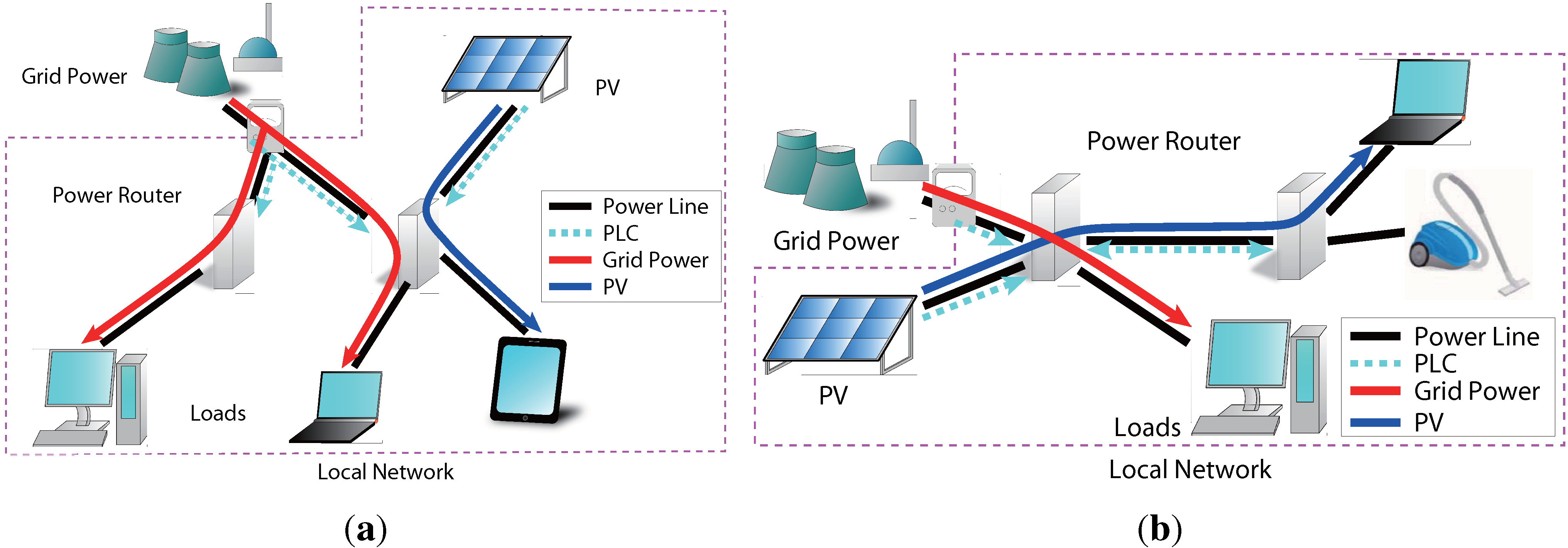
Figure 1 shows a schematic diagram of the connection setup of the AC power routing network system with the power router. The AC power router exchanges the lines to connect objective sources and loads appropriately according to the gathered demand and supply information. The power distribution system is expected to have a mesh network structure when power routers are applied. Thus, when several routes are shut down, it is possible to deliver power by finding an alternate path in the network. In addition, it is also possible to prevent the mixing of powers from different sources by implementing a time-dependent exchange. Therefore, the source derivation of each electric power stream must be guaranteed. In general, a network structure reduces to two connections, i.e., a parallel connection and a series connection. Figure 3(a) and Figure 3(b) shows examples of the parallel and series connections, respectively. In this study, in order to confirm the feasibility of the prospective power routers in a local network system, we verify the circuit switching operation by power routers depending on whether two power routers are connected in parallel or in series.
Figure 3. Elemental configurations of the network: (a) parallel configuration of power routers; and (b) series configuration of power routers.
Energies 06 06293 g003

3. Operation of AC Power Router

First, we verify the function of the single prototype AC power router for expected conditions experimentally. For this verification, we use two input ports 1 and 2, and two output ports A and B in the power router. Thus, we can select from two circuit topologies, i.e., “1 and A” and “2 and B” are connected or “1 and B” and “2 and A” are connected. After detecting the instance when the input voltages coincide with each other, the CPU in the power router sends a switching command signal to power switches in the routers to change the circuit topology. By causing the circuit to switch close to the equipotential instance, namely, equipotential switching, inrush current and surge voltage are suppressed [10]. However, it is inevitable to encounter some hard switching because of the delay between sending the switching signal and accomplishing the switch.
To confirm the operation of the AC power router, two experiments are performed with two input power voltage sources as follows:
Experiment I. 
input 1: 60 Hz/100 V rms , input 2: 60 Hz/90 V rms with no phase difference;
Experiment II. 
input 1: 60 Hz/100 V rms , input 2: 60 Hz/90 V rms with 120 phase difference.
The power voltage sources connected to inputs 1 and 2 are a commercial power and an independently simulated power source, respectively. The independently simulated power voltage source can be operated at an arbitrary frequency, amplitude and phase. In the above-mentioned experiments, we assume the simulated source as distributed power sources with and without phase synchronization of the commercial power source. Here, incandescent bulbs are set as loads.
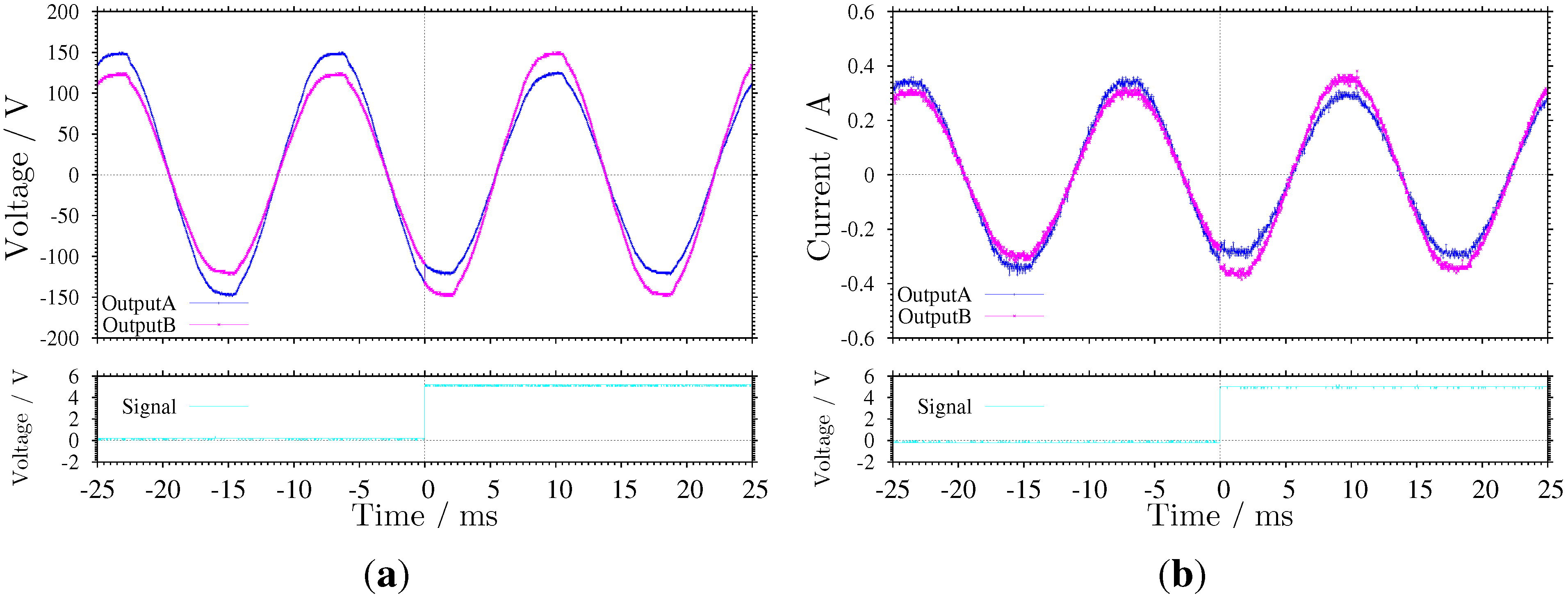
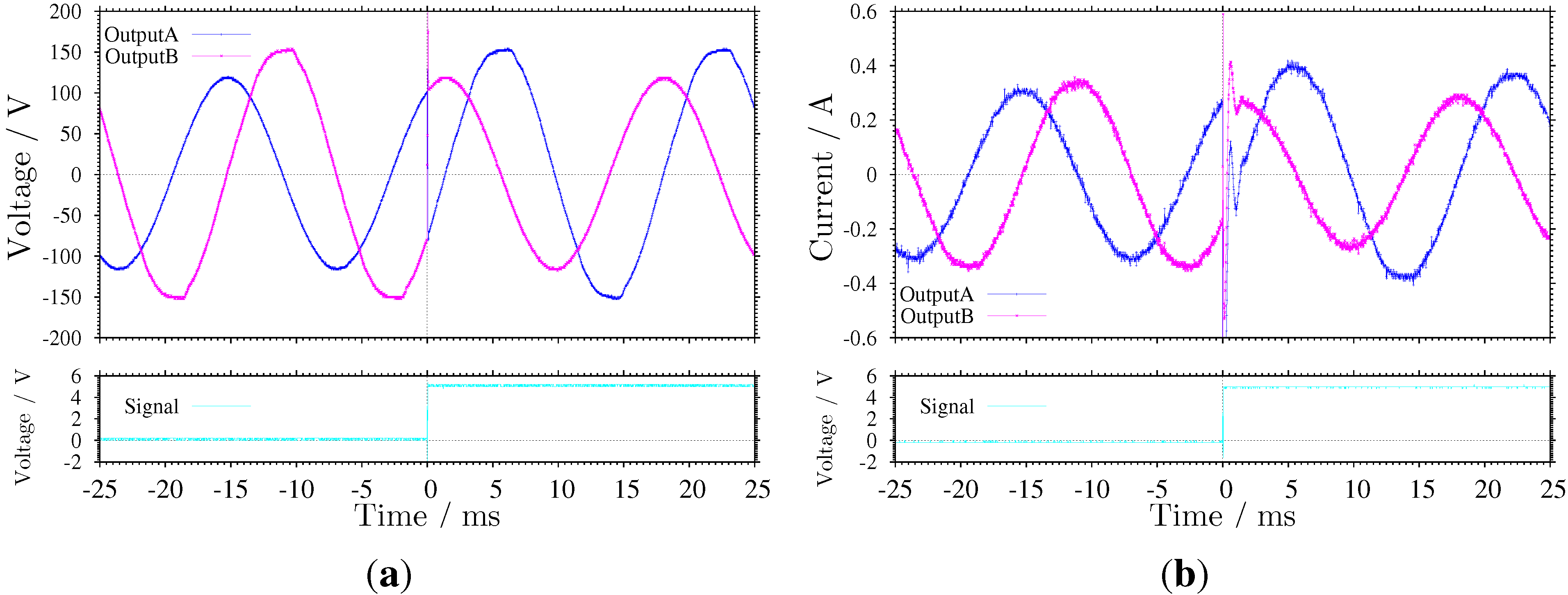
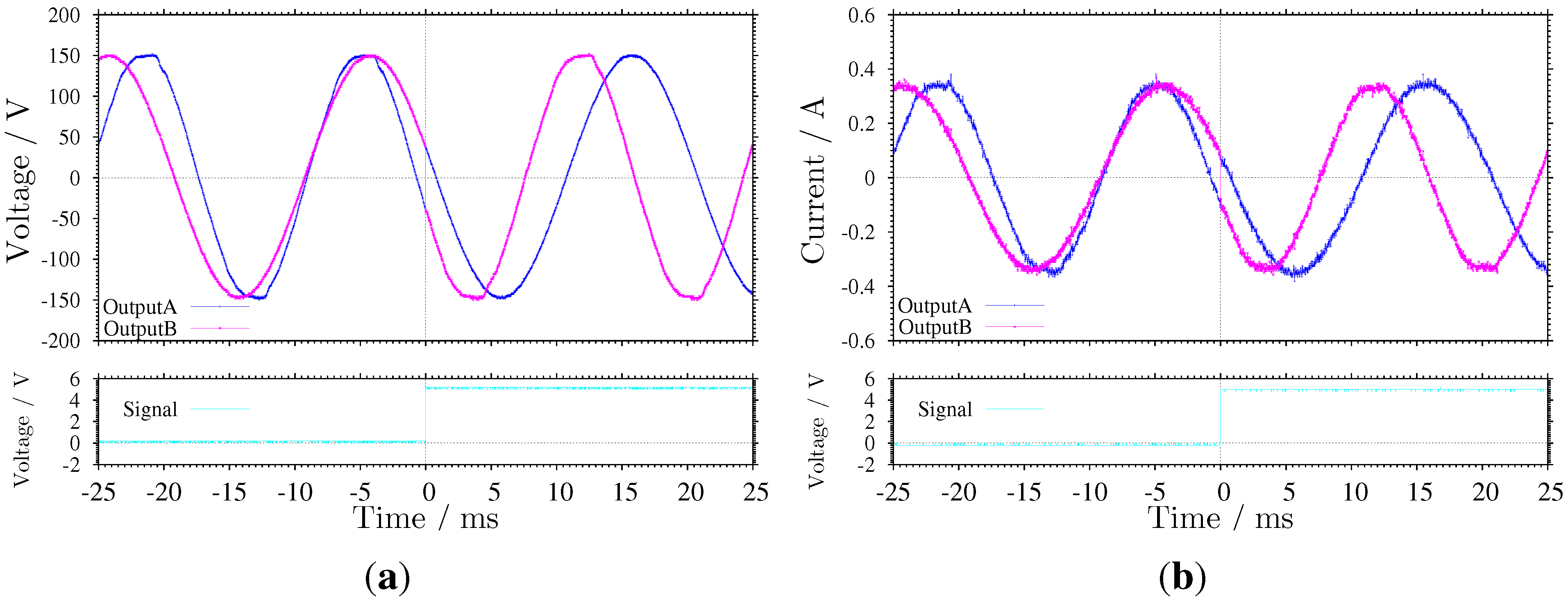
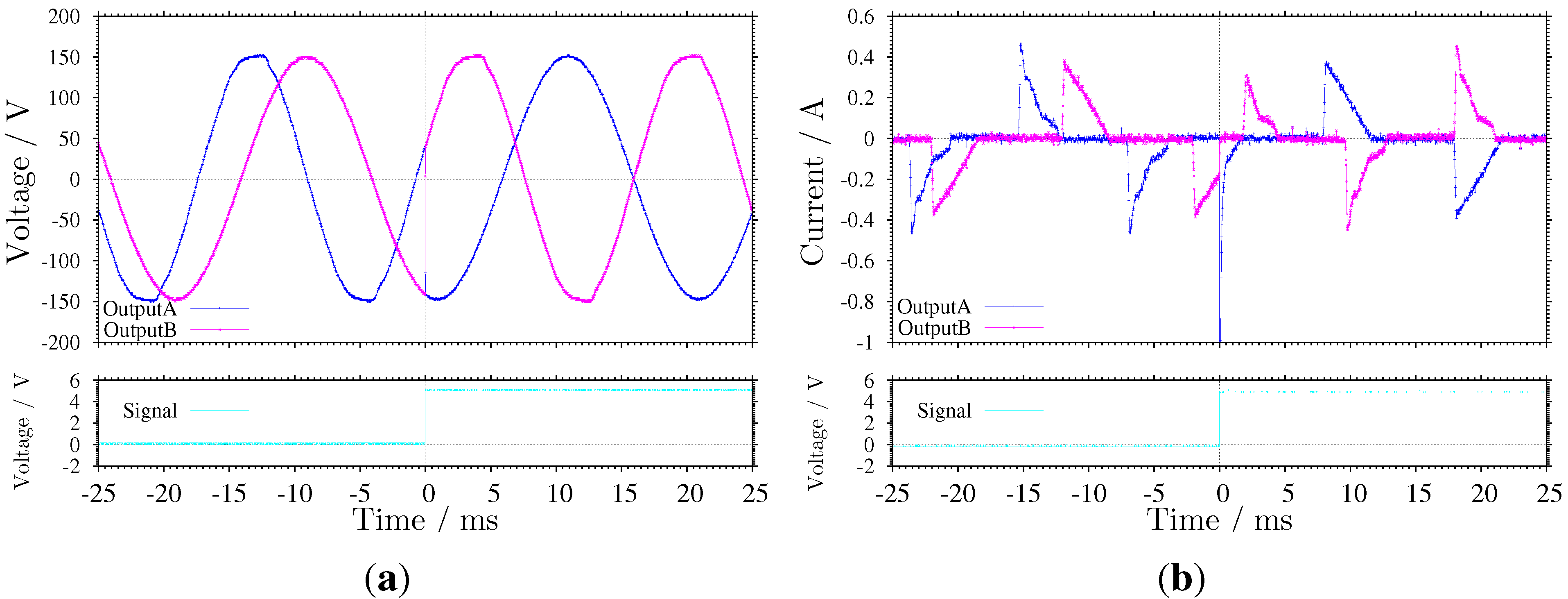
Figure 4 shows the measured output voltage and the current waveforms of the power router, respectively, under the phase synchronized condition, i.e., Experiment I. The lower boxes in (a) and (b) show the switching command signals. Conversely, Figure 5 shows these waveforms under out of phase synchronization, i.e., Experiment II.
Figure 4. Output waveforms of circuit switching operation with no phase difference between two inputs: (a) output voltage waveforms; and (b) output current waveforms.
Energies 06 06293 g004
Figure 5. Output waveforms of circuit switching operation with 120 phase difference between two inputs: (a) output voltage waveforms; and (b) output current waveforms.
Energies 06 06293 g005
From these results, it is determined that the power router succeeds in exchanging the lines after detecting the equipotential instance under both conditions. Moreover, the inrush current and surge voltage occur, especially in the out of phase synchronized condition. This is because there is a time delay between the detection of the equipotential instance and switching. This delay is essential to executing an algorithm in the CPU. The surge voltage and inrush current might prevent the switching from occurring. However, we confirmed that circuit switching can be performed successfully for the experimental parameters. The results show that the delay of the switching operation does not cause a switching failure in this case. An improvement of the algorithm in the CPU can obviously shorten the delay, so that the surge can be suppressed. Improvements to suppress the surge influence at the switching time and the quantitative evaluation of harmonics are inevitable in practical applications.

4. Parallel Connection of Power Routers
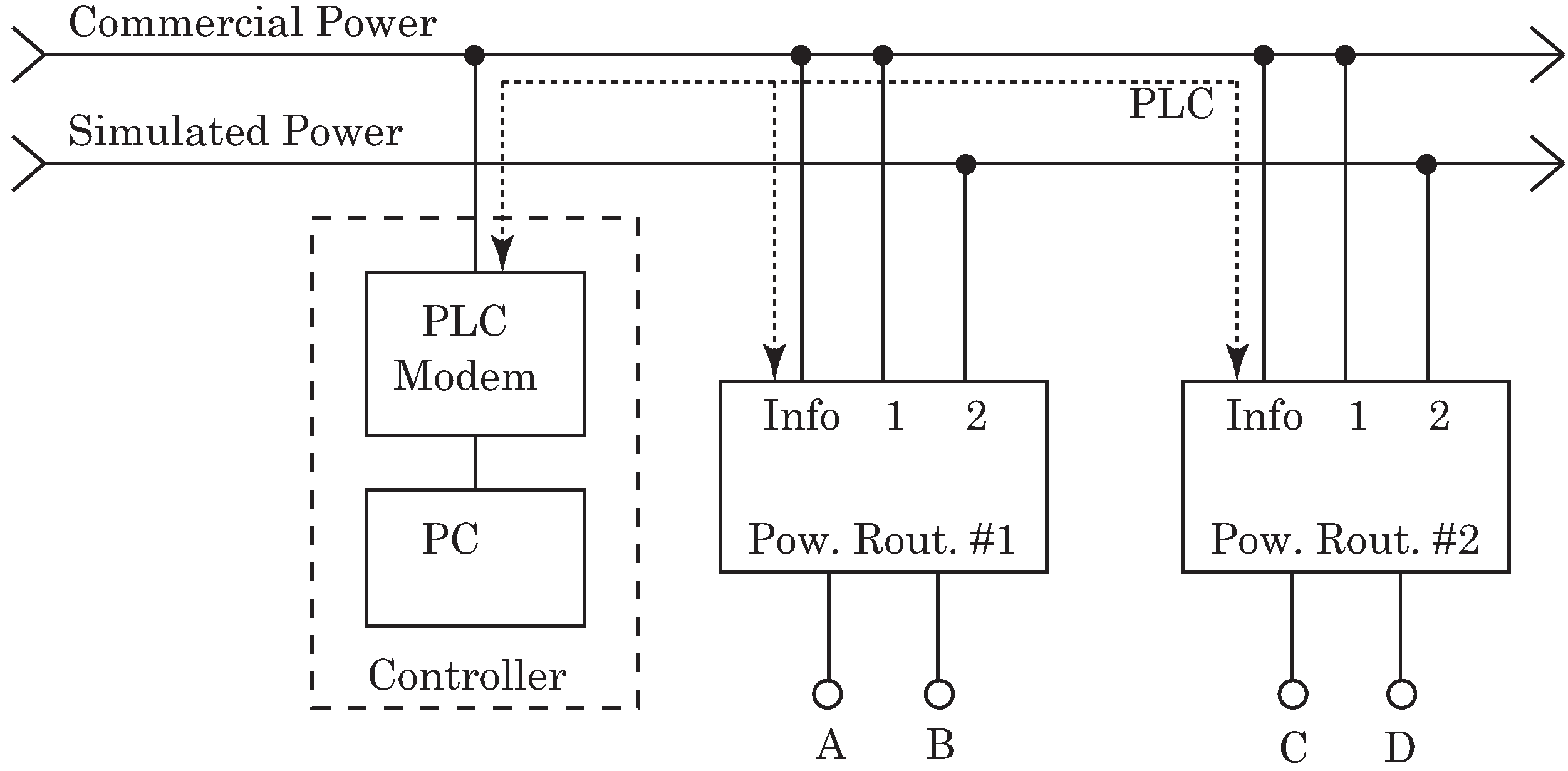
We verify the circuit switching operation in the parallel connection of the power routers. Figure 6 shows a schematic diagram of this experimental configuration. The controller for the power router is located upstream. We have explained that the developed information terminal controls each power router directly. However, a personal computer with a PLC modem may apply the same for remote exchanging of connections. It is feasible to establish a remote controlled routing network using the same control protocol. The simulated power is operated at 50 Hz/101 V rms . This implies that the system is under the out of phase synchronization scenario. A PLC modem is connected to the commercial PL. The communication between the power routers and the PC is established by the commercial PL by the PLC. Loads are connected to two output ports of the power router, A and B. The other output ports, i.e., C and D, are open circuits. We verify circuit switching by the power router in two cases that are different based on the connected load, i.e., incandescent bulbs or light-emitting diode (LED) bulbs. The incandescent bulb is considered to be an electric heating load. Meanwhile, the LED bulb is a constant current load that includes a regulator. For the setup, we measured the output voltages and currents of ports A and B to which the loads are connected.
Figure 6. Schematic diagram of a system in parallel connection.
Energies 06 06293 g006
Figure 7 and Figure 8 show the measured waveforms in the systems with incandescent bulbs or LED bulbs. From these figures, it is confirmed that circuit switching is successfully performed in both cases without switching failure. The LED bulbs generate the non-sinusoidal and intermittent current waveform because of the built-in regulator. From these results, it is noted that the circuit exchange can be performed after detecting the voltage cross point that is independent of the current waveform. However, note that the switching surge voltage would occur if there exists a difference between the input currents.
Figure 7. Output waveforms in parallel connection. Incandescent bulbs are set as loads: (a) output voltage waveforms; and (b) output current waveforms.
Energies 06 06293 g007
Figure 8. Output waveforms in parallel connection. Light-emitting diode (LED) bulbs are set as loads: (a) output voltage waveforms; and (b) output current waveforms.
Energies 06 06293 g008

5. Series Connection of Power Routers
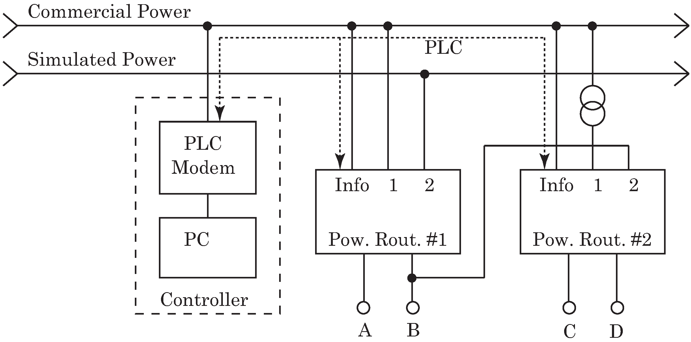
Here, we verify the circuit switching operation in series connected power routers. The controller for the power routers is located upstream. Figure 9 shows a schematic diagram of the experimental configuration for the series connection of the power routers. In addition, we number the power routers #1 as the upstream and #2 as the downstream router, respectively. Regarding power router #1, its input port 1 is connected to the 60 Hz/100 V rms commercial PL. Input port 2 of this power router is connected to the independently simulated PL, which is operated at the same parameters as in the previous parallel connection setting, i.e., 50 Hz/101 V rms . Conversely, regarding power router #2, 60 Hz/90 V rms stepped down power is fed to port 1. In addition, input port 2 of power router #2 is directly connected to output port B of power router #1. This implies that power routers #1 and #2 are connected in series. We set the incandescent bulbs at output ports C and D of the downstream power router #2. LED bulbs are set at output ports A and B of the upstream power router #1. Thus, the LED bulb is set on a branch of the line connecting power routers in series. The communication between the power routers and the PC is established by the commercial PL by the PLC. In this configuration, the communication channel is kept for PLC, because the line among the PLC modems is held.
Figure 9. Schematic diagram of a system in series connection.
Energies 06 06293 g009
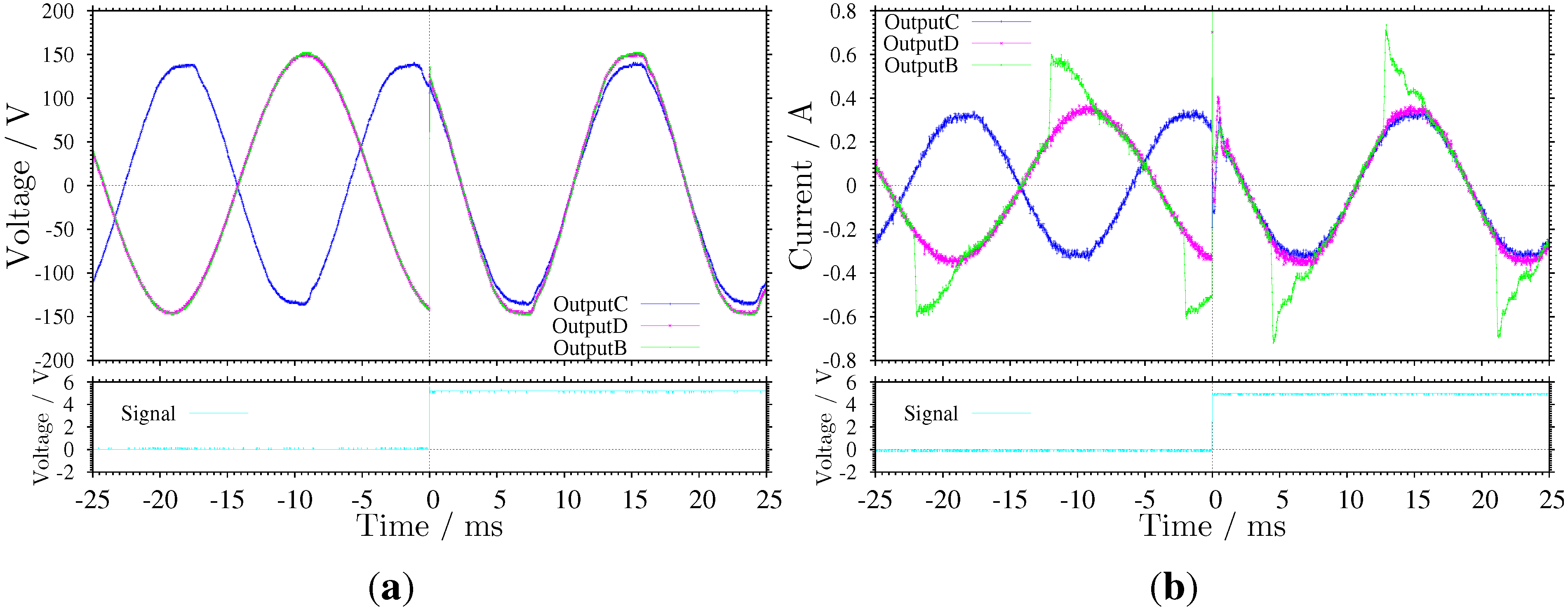
Figure 10 and Figure 11 show the output waveforms in a series connection. The former corresponds to the case where power router #1 has exchanged lines, and the latter corresponds to the case where power router #2 has exchanged lines. The current passing through power router #1 to power router #2 increases, because there are two loads on the path. The output current at port B is the sum of the currents, i.e., the pulse current to the LED bulb is added to the sinusoidal current to the incandescent bulb. From these figures, it is confirmed that circuit switching in the series configuration can be successfully performed without fatal error, even in the presence of these factors, such as the sum of the pulse and sinusoidal current waveforms, and out of synchronization.
Figure 10. Output waveforms in a series connection when the upstream power router #1 exchanges lines: (a) output voltage waveforms; and (b) output current waveforms.
Energies 06 06293 g010
Figure 11. Output waveforms in a series connection when the downstream power router #2 exchanges lines: (a) output voltage waveforms; and (b) output current waveforms.
Energies 06 06293 g011

6. Conclusion and Discussions

In this study, the feasibility of AC power routers is examined in a local power distribution network. The circuit switching operations in parallel and series configurations of the prototype AC power routers were confirmed experimentally to prove the feasibility of developing a switching network system. The results show that in parallel, as well as series configurations, the power router is able to exchange PLs successfully. Even if the input voltages are not synchronized in phase and frequency, the power router operates as in the case of synchronized sources. This behavior approximates the case of independently-driven power sources. Based on these results, it was determined that the AC power routing system should perform properly with a combination of parallel and series configurations.
Currently, a broadband PLC modem is installed in the prototype power router. In general, it is difficult to establish communication between two PLC modems over lines with transformers. However, a narrowband PLC has attracted interest in smart grids, because it is expected to establish communications when transformers are present [18]. A change in PLC modem type should not represent any substantial problems for establishing a network using power routers of the type discussed in this study. A time delay of the signal transmission over the system should not become a serious problem, because the period of the voltage cross point when circuit switching is performed is sufficiently large compared to the signal propagation time. In addition, the development of a SiC power device is most expected to be installed in the power router to allow the exchange of PLs with higher voltages [19]. The implementation of SiC power devices is inevitable to enlarge the power management capacity in the power router and to decrease the conduction and switching losses that constitute the main power losses in the power router. The power efficiency of the prototype power router with Si power devices is 99.67% under steady-state conditions [10]. In addition, SiC power devices are expected to reduce losses by 90% compared with Si devices in the same voltage class [20], which would represent significant reduction in waste power on a national or global scale. With the use of the power router we have developed, we have opened the door to a power routing system that satisfies the management of power distribution according to energy on demand.

Acknowledgments

This research is partially supported by the National Institute of Information and Communications Technology, Japan. The authors would like to thank Sumitomo Electric Networks, Inc. and Synthesize, Ltd., for the fabrication of the AC power router and the information terminal.

Conflicts of Interest

The authors declare no conflict of interest.

References

  1. Toyoda, J.; Saitoh, H. Proposal of an Open-Electric-Energy-Network (OEEN) to Realize Cooperative Operations of IOU and IPP. In Proceedings of the 1998 International Conference on Energy Management and Power Delivery (EMPD), Singapore, 5 March 1998; Volume 1, pp. 218–222.
  2. Sakai, K.; Okabe, Y. Quality-Aware Energy Routing toward On-Demand Home Energy Networking. In Proceedings of the 2011 IEEE Consumer Communications and Networking Conference (CCNC), Las Vegas, NV, USA, 9–12 January 2011; pp. 1041–1044.
  3. Hikihara, T. Power Router and Packetization Project for Home Electric Energy Management. In Presented at the Santa Barbara Summit on Energy Efficiency, Santa Barbara, CA, USA, 12–13 May 2010.
  4. Hikihara, T.; Tashiro, K.; Kitamori, Y.; Takahashi, R. Power Packetization and Routing for Smart Management of Electricity. In Proceedings of the AIAA/IECEC 10th International Energy Conversion Engineering Conference, Atlanta, GA, USA, 29 July–1 August 2012.
  5. Takuno, T. High Frequency Switching of SiC Transistors and Its Applications to In-Home Power Distribution. Ph.D. Thesis, Kyoto University, Kyoto, Japan, 2012. [Google Scholar]
  6. Takuno, T.; Koyama, M.; Hikihara, T. In-Home Power Distribution Systems by Circuit Switching and Power Packet Dispatching. In Proceedings of the 2010 First IEEE International Conference on Smart Grid Communications, Gaithersburg, MD, USA, 4–6 October 2010; pp. 427–430.
  7. Tashiro, K.; Takahashi, R.; Hikihara, T. Feasibility of Power Packet Dispatching at In-Home DC Distribution Network. In Proceedings of the 2012 Third IEEE International Conference on Smart Grid Communications, Tainan, Taiwan, 5–8 November 2012; pp. 401–405.
  8. Takahashi, R.; Azuma, S.; Tashiro, K.; Hikihara, T. Design and Experimental Verification of Power Packet Generation System for Power Packet Dispatching System. In Proceedings of the 2013 American Control Conference, Washington, DC, USA, 17–19 June 2013; pp. 4368–4373.
  9. Takahashi, R.; Takuno, T.; Hikihara, T. Estimation of power packet transfer properties on indoor power line channel. Energies 2012, 5, 2141–2149. [Google Scholar] [CrossRef] [Green Version]
  10. Takuno, T.; Kitamori, U.; Takahashi, R.; Hikihara, T. AC power routing system in home based on demand and supply utilizing distributed power sources. Energies 2011, 4, 717–726. [Google Scholar] [CrossRef] [Green Version]
  11. Stalling, B.P.; Clemmer, T.; Mantooth, H.A.; Motte, R.; Xu, H.; Price, T.; Dougal, R. Design and Evaluation of a Universal Power Router for Residential Applications. In Proceedings of the 2012 IEEE Energy Conversion Congress and Exposition (ECCE), Raleigh, NC, USA, 15–20 September 2012; pp. 587–594.
  12. He, M.M.; Reutzel, E.M.; Jiang, X.; Katz, R.H.; Sanders, S.R.; Culler, D.E.; Lutz, K. An Architecture for Local Energy Generation, Distribution, and Sharing. In Proceedings of the IEEE Energy 2030 Conference, Atlanta, GA, USA, 17–18 November 2008; pp. 1–6.
  13. Gelenbe, E. Energy Packet Networks: Adaptive Energy Management for the Cloud. In Proceedings of the 2nd International Workshop on Cloud Computing Platforms, Bern, Switzerland, 10 April 2012. Article No. 1.
  14. Gelenbe, E. Energy Packet Networks: ICT Based Energy Allocation and Storage. In Green Communications and Networking; Rodrigues, J.J.P.C., Zhou, L., Chen, M., Kailas, A., Eds.; Springer: Berlin, Germany, 2012; Volume 51, pp. 186–195. [Google Scholar]
  15. Gelenbe, E. Quality of Information and Energy Provisioning. In Proceedings of the 5th International Workshop on Information Quality and Quality of Service for Pervasive Computing, San Diego, CA, USA, 22 March 2013; pp. 453–457.
  16. Yoshihisa, T.; Fujita, N.; Tsukamoto, M. A Rule Generation Method for Electrical Appliances Management Systems with Home EoD. In Proceedings of the 2012 IEEE 1st Global Conference on Consumer Electronics (GCCE), Tokyo, Japan, 2–5 October 2012; pp. 248–250.
  17. Miyamoto, T.; Koyama, Y.; Sakai, K.; Okabe, Y. A GMPLS-Based Power Resource Reservation System toward Energy-on-Demand Home Networking. In Proceedings of the 2012 IEEE/IPSJ 12th International Symposium on Applications and the Internet (SAINT), Izmir, Turkey, 16–20 July 2012; pp. 138–147.
  18. Galli, S.; Scaglione, A.; Wang, Z. For the grid and through the grid: The role of power line communications in the smart grid. IEEE Proc. 2011, 99, 998–1027. [Google Scholar] [CrossRef]
  19. Miyake, H.; Okuda, T.; Niwa, H.; Kimoto, T.; Suda, J. 21-kV SiC BJTs with space-modulated junction termination extension. IEEE Electron Device Lett. 2012, 33, 1598–1600. [Google Scholar] [CrossRef]
  20. Noborio, M.; Suda, J.; Kimoto, T. 4H-SiC lateral double RESURF MOSFETs with low on resistance. IEEE Trans. Electron Devices 2007, 54, 1216–1223. [Google Scholar] [CrossRef] [Green Version]