Article

A Novel Pumped Hydro Combined with Compressed Air Energy Storage System

School of Energy and Power Engineering, Xi'an Jiaotong University, Xi'an 710049, China
*
Author to whom correspondence should be addressed.
Energies 2013, 6(3), 1554-1567; https://doi.org/10.3390/en6031554
Submission received: 21 December 2012 / Revised: 10 February 2013 / Accepted: 18 February 2013 / Published: 11 March 2013

Abstract

:
A novel pumped hydro combined with compressed air energy storage (PHCA) system is proposed in this paper to resolve the problems of bulk energy storage in the wind power generation industry over an area in China, which is characterised by drought and water shortages. Thermodynamic analysis of the energy storage system, which focuses on the pre-set pressure, storage volume capacity, water air volume ratio, pump performance, and water turbine performance of the storage system, is also presented. This paper discovers how such parameters affect the performance of the whole system. The ideal performance of this novel system has the following advantages: a simple, highly effective and low cost structure, which is comparable to the efficiency of a traditional pumped hydro storage system. Research results show a great solution to the current storage constraints encountered in the development of the wind power industry in China, which have been widely recognised as a bottleneck in the wind energy storage industry.

1. Introduction

Research on energy storage systems using modern technologies started nearly 150 years ago, and many useful ideas have since been employed worldwide. Using storage technologies combined with green power sources is one of the methods for reducing the negative effects of these resources on power systems [1]. However, there are still problems in the modern industry for such large-scale energy storage systems. Energy storage technologies are still hot research topics in the energy and power industry field. In China, the wind power industry has been developing rapidly in the past 20 years, and large scale energy storage has become very prominent; this has been recognised as a key area in the development of wind power industry in China. As wind energy fluctuates, randomness causes the existing national grid to be unstable if wind power joins the national grid. In order to find a proper way to store the electricity generated by the wind and make the national grid run smoothly, the current paper—funded by the Chinese Ministry of Science and Technology—proposes a novel methodology for a large-scale energy storage system in a drought-prone area.
Throughout the course of the development of energy storage, energy storage technologies can be divided into two categories. One is the physical storage, and the other is electrochemical energy storage. Electrochemical energy storage can be categorised into batteries, fuel cells, and electrolytic hydrogen. The method of physical storage can be categorised into pumped hydro storage, compressed air storage, super capacitor energy storage, flywheel energy storage, and liquefied air energy storage. Table 1 shows the comparison of several main energy storage systems [2].
Table 1. Capital cost of installed storage plants.
TypeStorage Capital Cost ($/kWh)Plant Capital Cost ($/kW)Storage Capital (MWh)Efficiency (%)Operation and maintenance cost ($/kW/yr)Hours (full power )Power (MW)
CAES>3>4255–100,000>701.351–10 min0.5–2700
Pumped Hydro >10>600>20,000>704.310 s–4 min300–1800
Flywheel300–25,000280–3600.0002–50090–937.5<1s0.001–1
Superconducting Magnet 500–72,0003000.0002–100951<1s0.001–2
Battery Storage 1–15500–15000.0002–259-<1s0.01–3
According to [3,4], there are only two kinds of mature technology suitable for wind power storage: pumped hydro energy storage (PHES) and compressed air energy storage (CAES). With high power level and technology, these energy storage technologies can be applied in very large-scale power systems, and are realised in commercial application.
Current wind power development in China has encountered a completely different natural environment with other countries in the World, and PHES has been constrained by market uncertainties, localisation difficulties, and environmental impacts [4]. Consequently, PHES cannot be used to store the vast majority of wind power in China.
As an alternative to PHES, CAES is a promising energy storage method, with high reliability, high economic feasibility, and low environmental impact [5,6]. Meanwhile, the feasibility of using CAES in storing wind energy has been studied [7,8,9,10]. Grazzini et al. [11] proposed the concept of Advanced Adiabatic Compressed Air Energy Storage (AA-CAES) and Kim et al. [12] proposed a water-compensated CAES system, which utilises a water head supplied by an aboveground reservoir to keep the storage cavern at a constant pressure throughout operation. The two novel systems can save energy, but their structures are complicated and existing CAES systems require extra power to increase the air temperature, thus leading to high energy storage costs. In order to resolve the energy storage problem in those arid areas, the current paper proposes a new energy storage system, which combines the advantages of the PHES and CAES system. The novel system is called pumped hydro combined with compressed air energy storage (PHCA). This paper establishes a theoretical mathematical model for the analysis of the process of energy storage and power generation. Parameters such as pre-set pressure, storage volume capacity, water air volume ratio, pump performance and water turbine performance, which all affect the performance of the storage system, have been theoretically analysed in the current paper.

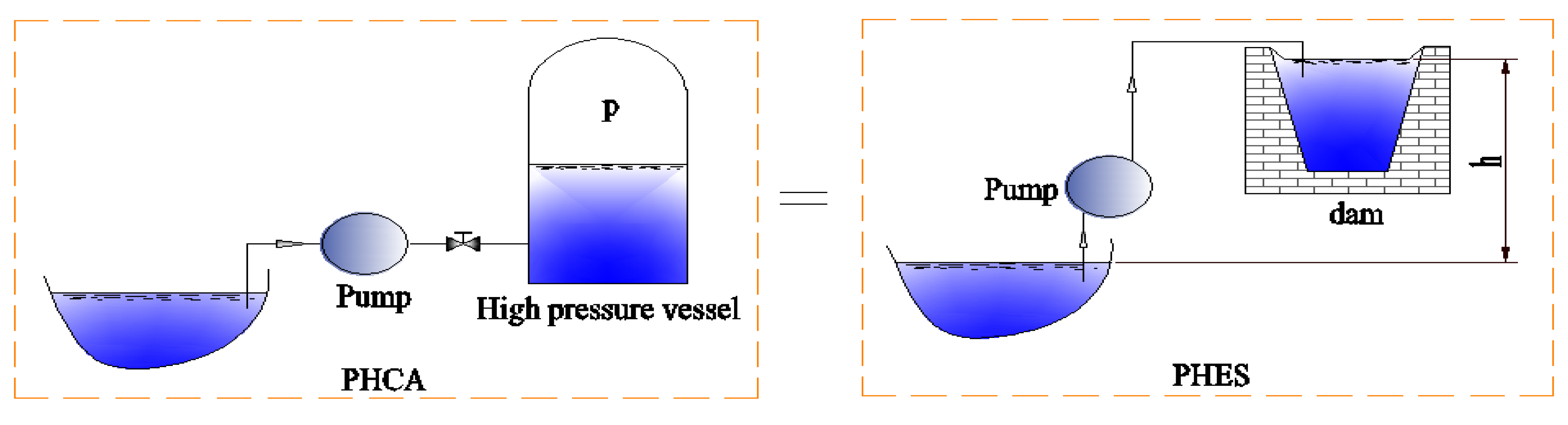
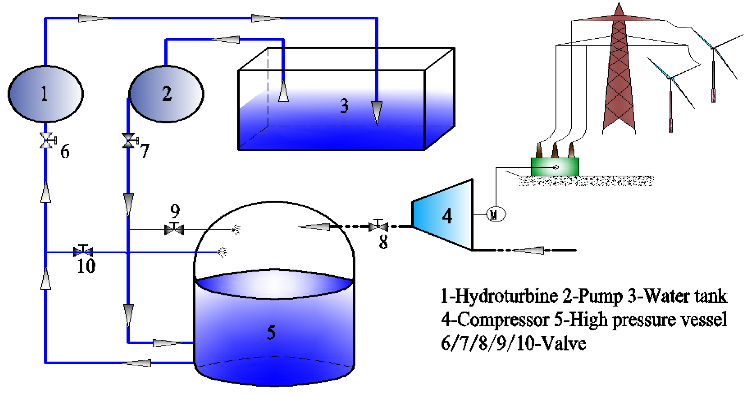
2. Physical Model and Working Principles

A PHES facility is typically equipped with reversible pumps or generators connecting an upper and a lower reservoir. During off-peak hours, the pumps utilise relatively cheap electricity from the grid to move water from the lower reservoir to the upper one in order to store energy. Meanwhile, during periods of high electricity demand (peak-hours), water is released from the upper reservoir to generate power at a higher cost [13].The major problem of this system is that it demands special geological conditions with rich long-life water sources and relatively low evaporation. How is this technology to be employed in a drought area or plain? The system proposed in this paper shows a good solution to the problem. As shown on the left of Figure 1, a pump is connected to an air container through a valve, and when water is pumped to the vessel, the pressure of the air increases as the volume is fixed. This is equivalent to raising the water level, as shown on the right side of Figure 1. For example, if the pressure of the air in the vessel is 5 MPa, this is equivalent to a dam with a height of 500 m, and when the pressure reaches 10 MPa, this is equivalent to a dam with a height of 1000 m.
Figure 1. Physical model of the PHCA.
Energies 06 01554 g001
Based on the abovementioned principle, a system for energy storage in a drought area using pumps and compressive air vessels is presented in the current paper, in an attempt to build a non-existing dam with a height that can be adjusted by controlling the vessel pressure. The system consists of a high pressure vessel, a closed pond connected to the atmosphere, a set pump driven by electricity, and a water turbine connected to a generator (Figure 2).
Figure 2. Schematic of the PHCA.
Energies 06 01554 g002
Initially closed valves include valves 6, 7, 9, and 10 (Figure 2); the open valves include valve 8, which starts compressor 4 and pumps the air to the vessel, thereby setting up a pre-set pressure in vessel 5. Compressor 4 and valve 8 are closed when the pre-set pressure has built up. The compressor 4 works only for creating the initial pressure. For storing energy, we open valves 7 and 9, and inject water to vessel 5 by starting the high pressure pump 2. The pressure in the vessel goes up when the water surface rises during the injection period. In addition, the air temperature of the compressed air in the vessel will increase, and the pumping process becomes more and more difficult. Pump energy for unit volume water is then increased and stored in the vessel, which is equivalent to the height of the dam as it increases. At the same time, a small amount of water flowing is sprayed through valve 9 to the compressed air in order to decrease the air temperature. When the target air pressure in the vessel is reached, valves 7 and 9 are closed and the energy storage process is finished. For the energy generation process, valves 6 and 10 are opened. At this point, high pressure water pushes the hydro turbine, which powers the generator, consequently generating electricity. Exhausted water then goes back to the closed pond 3, which is connected to the atmosphere. Meanwhile, a small amount of water flowing through valve 10 is sprayed to the expanded air and exchanges heat with the air. The gas turbine and gas combustion chamber are not required in this system though they are quite often used in a compressed air storage system.

3. Characteristic of the PHCA System

According to the Second Law of thermodynamics, thermal energy cannot be converted to mechanical energy completely, and some would be transferred to a lower temperature object, while mechanical energy can be totally converted to thermal energy. This implies that the quality of mechanical energy is better than that of thermal energy [14]. Experience shows that mechanical energy is one of the highest “quality” energies of all forms with an extremely wide range of applications. In the PHCA, energy is converted from mechanical energy (pressure energy) to electrical energy through the turbine, and thus easily to infer that the energy utilization of PHCA system is theoretically higher than that of CAES system in terms of energy quality.
In addition, from the working process above, the thermal machinery (compressor/expansion) of the CAES is substituted by hydraulic machinery (pump/hydro turbine) of the PHCA system in the process of energy storage and power generation. Generally, the density of gas is about 1/1,000 of the density of water, therefore, the power density of hydraulic machinery is larger than that of the corresponding thermal machinery. For example, in order to obtain a shaft power of 600,000 kW, the working medium in the turbine needs to get through sixty stages continuously with an initial pressure of 25 MPa, while for the hydro turbine, the same power can be obtained after the working medium goes through one stage of energy conversion with an initial pressure of 1~3 MPa, so the structure of hydraulic machinery is more simple than that of thermal machinery.
Due to the high power density of hydraulic machinery, an excessive high energy head is not required and hydraulic machinery does not need to be multistage. Hydro turbines being used in practical engineering are basically single-stage units. The adjustment of single-stage structure is much more convenient than that of multistage structure and the total efficiency of modern large hydro turbine has reached more than 95%, the highest efficiency of all the prime movers.
Many novel systems cannot be put in reality due to the high cost. In this paper, the main equipment cost of 1 MW energy storage is investigated and the total cost thus inferred (including electrical and controls, construction materials, labor, indirect costs and so on) according to [15,16]. The results are shown in Table 2, from which we can see the total cost of PHCA is less than that of the other two.
Table 2. Main equipment cost comparison of 1 MW energy storage systems.
TypeEquipmentCost (RMB)Cost Fraction (%)Total (RMB)
CAES aCompressor220112003
Heat Exchanger804
Expander54127
High Pressure Vessel20010
PHES bPump12462066
Hydro Turbine24812
PHCACompressor80501704
Pump124
Hydro Turbine248
High Pressure Vessel400
a Cost was provided by Shenyang Blower Works Group Corporation; b Cost was provided by Sichuan Jiannan Hydro Turbine Works.
Compared with CAES [11,12,17], the PHCA has the advantages listed below:
  • Simple structure. In the process of energy storage and power generation of the CAPW, cooler and auxiliary heating systems are not required.
  • High efficiency. The efficiency of the water pump and water turbine are both higher than that of the compressor and expander; thus, the efficiency of the CAPW has a more improved space than the CAES.
  • Low cost. In the same scale of energy storage system, the costs of high pressure water pump and hydro turbine are less than those of the compressor and expander; furthermore, the CAPW does not need a cooler or heater, thereby saving system cost.
Compared with the structure of PHES [14], the PHCA does not need special geologic conditions. Moreover, it has the advantages of little water supply and evaporation problems, and water energy storage density can be easily changed.

4. Thermodynamic Analysis of the PHCA System

In order to simplify the problem, the PHCA model uses the simplifications and assumptions listed below:
  • The gas in the vessel is assumed to be nitrogen due to its very low solubility in the water and the fact it is inactive and easily accessible.
  • Nitrogen can be treated as ideal gas, and hydraulic water is incompressible in the thermodynamics analysis.
  • The vessel is considered as an adiabatic container to make the analysis of the PHCA system simplified to calculate.
  • There is no net transfer of water vapor between the water and nitrogen and no pressure loss in the pipes of the gas liquid flows.

4.1. Initial Compression Process

Gas injection at a high pressure vessel is a typical non-steady state process. Outlet gas condition from the compressor varies with the vessel pressure, such as its pressure and mass flow rate, therefore the compressor is working under a non-steady process condition. The real compression process can be treated as an overlap of many tiny steady compression processes. In the adiabatic compression process, work per unit mass of the gas injection is calculated using the formula given as follows:
w = k k 1 R g n T 0 [ ( p p 0 ) k 1 k 1 ) ]
where, p0 is the initial pressure of the vessel; and p1 is the pre-set pressure of the vessel.
Assuming that the total volume is Vh, then according to the ideal gas equation, we have the following:
d m a = d ( p V h R g n T 0 ) = V h R g n T 0 d p
The total gas mass is injected as follows:
m a = p 0 p 1 d m = p 0 p 1 V h R g n T 0 d p = V h R g n T 0 ( p 1 p 0 )
The total energy consumption can then be presented as:
W c = 1 2 w d m a = p 0 p 1 k V h k 1 [ ( p p 0 ) k 1 k 1 ] d p = k V h k 1 [ k 2 k 1 p 0 1 k k ( p 1 2 k 1 k p 0 2 k 1 k ) ( p 1 p 0 ) ]

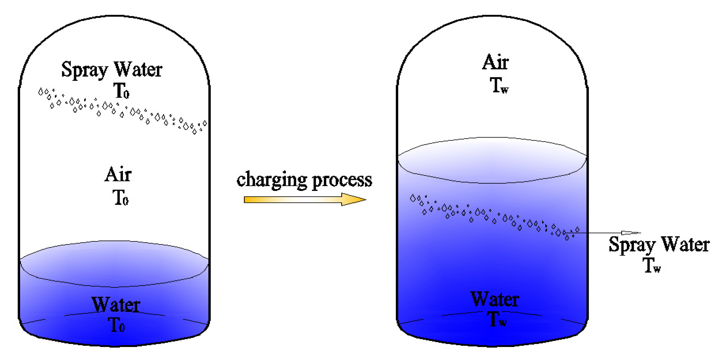
4.2. Water Injection Process for Energy Storage

In this process, the high pressure water pump injects water into the water-air mix up vessel. As the water level rises, the nitrogen in the vessel is compressed. At the same time, the water flowing through valve 9 is sprayed onto the compressed air so as to decrease the air temperature. This process is shown in Figure 3.
Figure 3. Temperature in the charging process.
Energies 06 01554 g003
When the process of energy storage is completed, the injection water mass is given by the following:
m w = ρ w V w
After water feeding and before heat exchange between nitrogen and water, the gas temperature is as follows:
T 2 = T 0 ( 1 + ε ) k 1
where ε is the volume ratio of water to air:
ε = V w V h V w
After heat exchange between water and nitrogen, water temperature Tw becomes the following:
C p n m a ( T 2 T w ) = C p w m w ( T w T 0 )
where T0 is the environmental temperature as well as the initial temperature of water and air.
Combining Equations (5–8), Tw could be resolved by the following formula:
T w = 1 + D ( p 1 p 0 ) ( 1 + ε ) k ε 1 + D 1 + ε ε ( p 1 p 0 ) T 0
where:
D = C p n R g n T 0 C p w ρ w
From Equation (9) water temperature variation with volume ratio and pre-set pressure are shown in Figure 4 and Figure 5.
Figure 4. Water temperature various with water air volume ratios.
Energies 06 01554 g004
Figure 5. Water temperature various with pre-set pressure.
Energies 06 01554 g005
As shown in Figure 5 and Figure 6, water temperature is relevant to the volume and pre-set pressure, but does not change much (less than 5 °C) during the water injection process; therefore, this process can be recognized as an isothermal process as follows:
p V = c o n s t
Similarly, the air temperature decreases through air expansion before heat exchange occurs between air and sprayed water in the discharge process. The temperature changing process becomes the same as that in the water injection process; thus, this discharge process can be recognised as an isothermal process.
After the isothermal water charging, nitrogen pressure is p2, then water volume is given by the following:
V w = V h p 1 V h p 2 = V h p 2 p 1 p 2
Charged water mass becomes as follows:
m w = ρ w V w
If the height difference between the pond and the vessel is negligible then pump work per unit mass would be given by the following:
w w = p 1 p 2 1 ρ w d p
Total pump energy consumption is given as follows:
W p = w w m w / η p = ( p 2 - p 1 ) V w / η p = p 1 V W 2 V h V w / η p = V h ( p 2 p 1 ) 2 p 2 / η p

4.3. Electricity Generation

If all energy losses are neglected, water pump energy consumption should be equal to the work produced by the water turbine energy; therefore, water turbine work is given as follows:
W t = w w m w η t = ( p 2 - p 1 ) V w η t = p 1 V w 2 V h V w η t = V h ( p 2 p 1 ) 2 p 2 η t

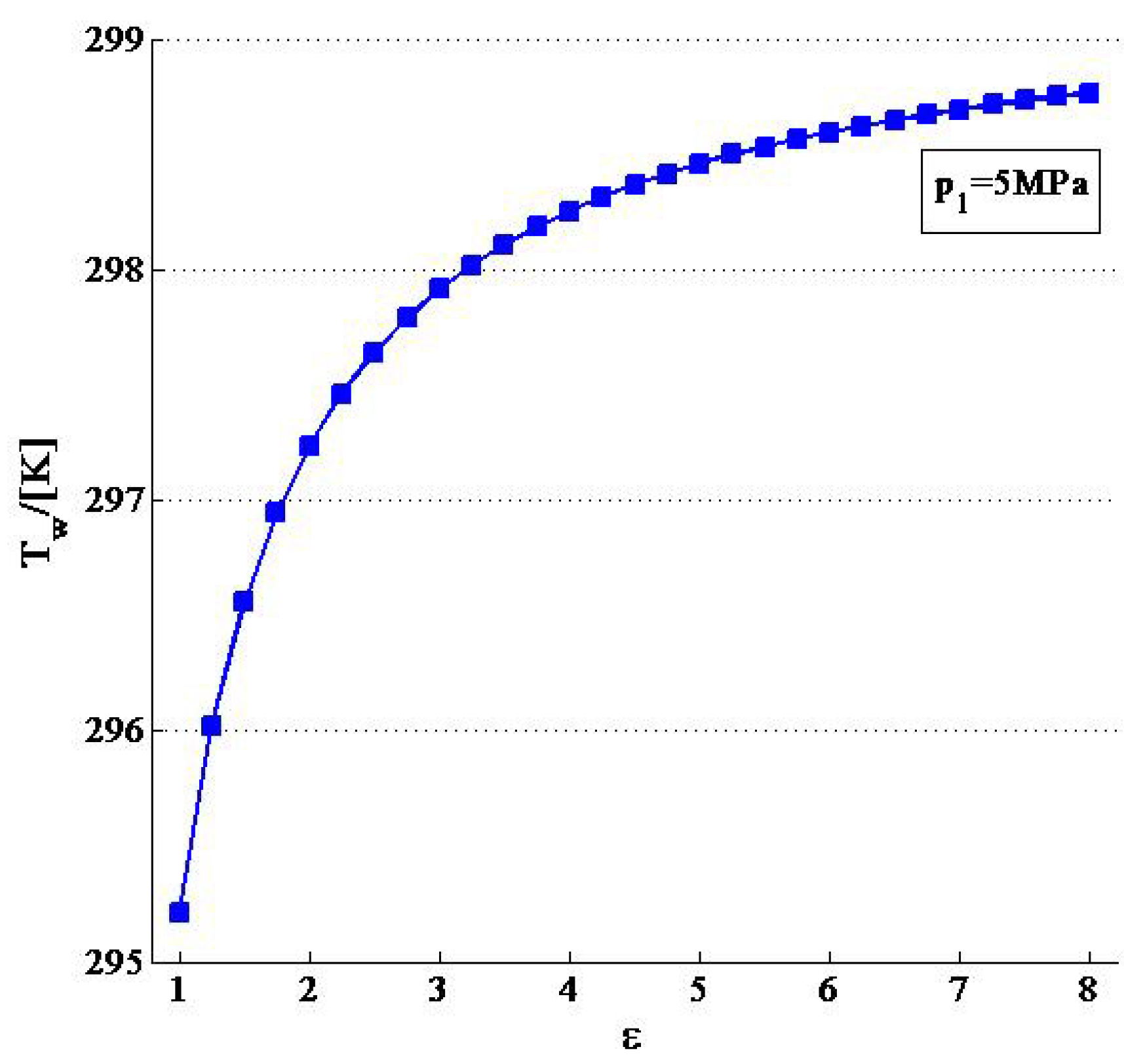
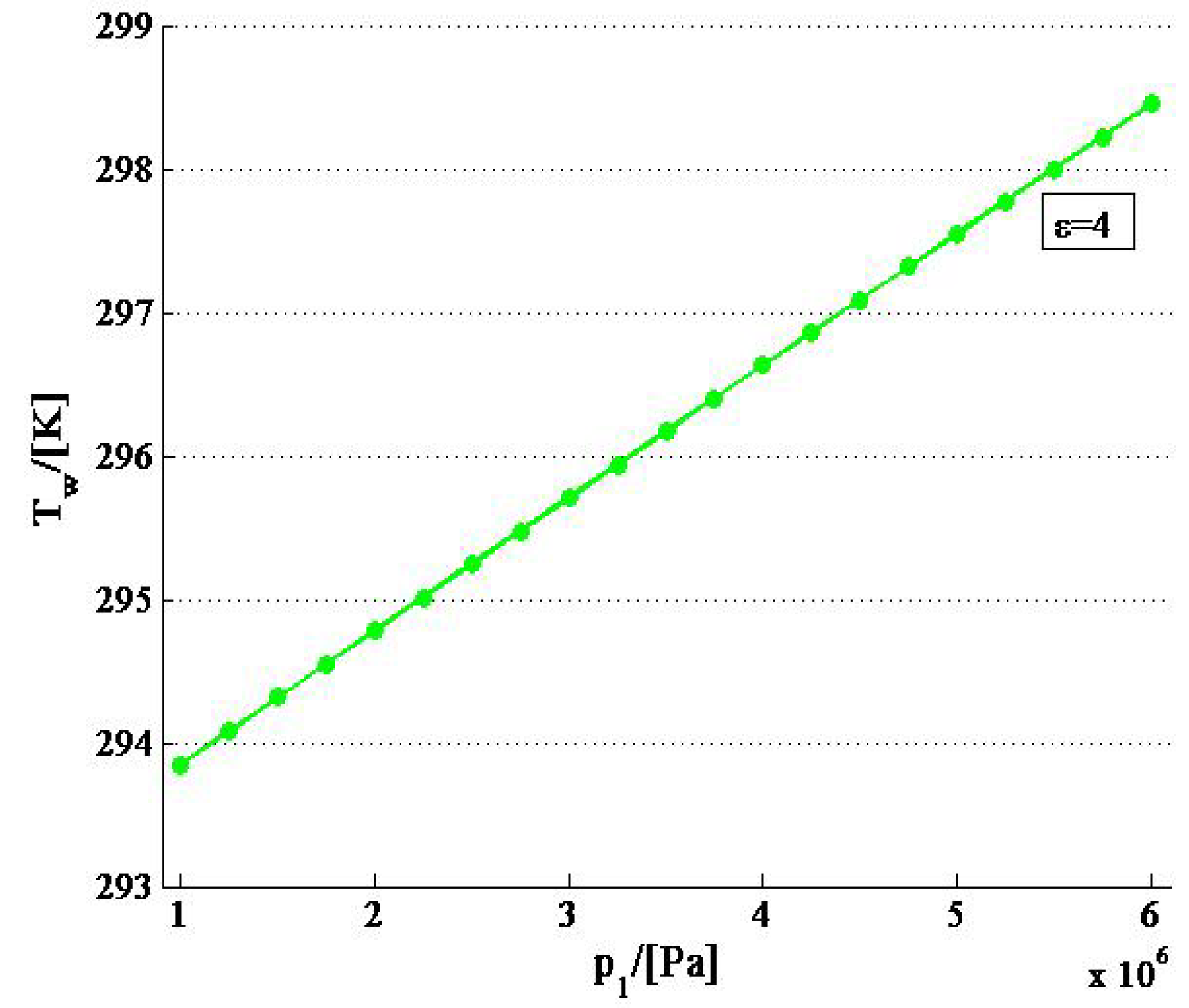
5. Analysis and Discussion of Influencing Parameters

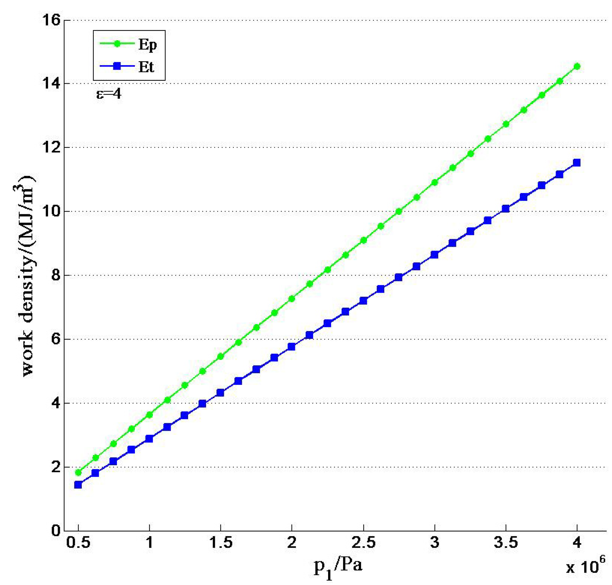
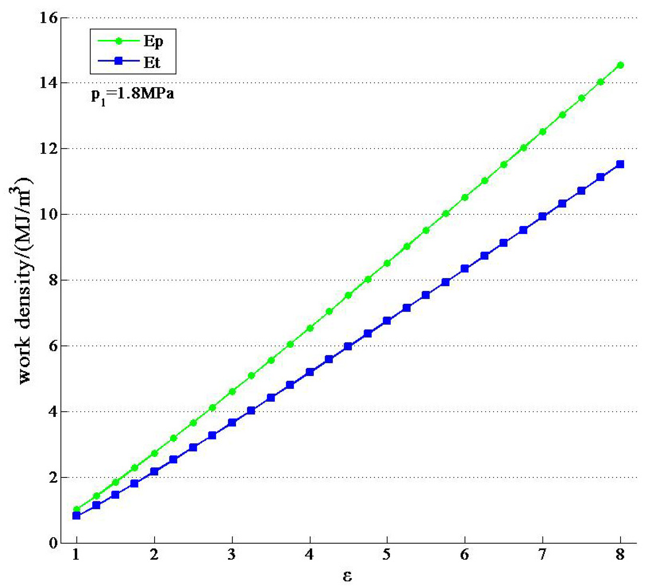
5.1. The Influences of Work Density

The pressure vessel is one of the most important facilities in the PHCA, because its capacity affects the cost of system; thus, the total work input and output per cubic meter must be identified in order to optimise the system. According to Equations (6,15,16):
W p = V h p 1 ε 2 1 + ε / η p
W t = V h p 1 ε 2 1 + ε η t
Then, work density is defined as follows:
E p = W p V h = p 1 ε 2 1 + ε / η p
E t = W t V h = p 1 ε 2 1 + ε η t
Pump and water turbine work density varies against pre-set pressure, and water-air volume ratio is shown in Figure 6 and Figure 7.
Figure 6. Work density various with pre-set pressure.
Energies 06 01554 g006
Figure 7. Work density various with water-air volume ratio.
Energies 06 01554 g007
Both items increase when pre-set pressure and water-air volume ratio is increasing. Moreover, the work density can reach 16 MJ/m3 with maximum pressure of 20 MPa which was chosen for the PHCA in consideration of the energy density and allowable pressure of the storage and hydraulic machinery.

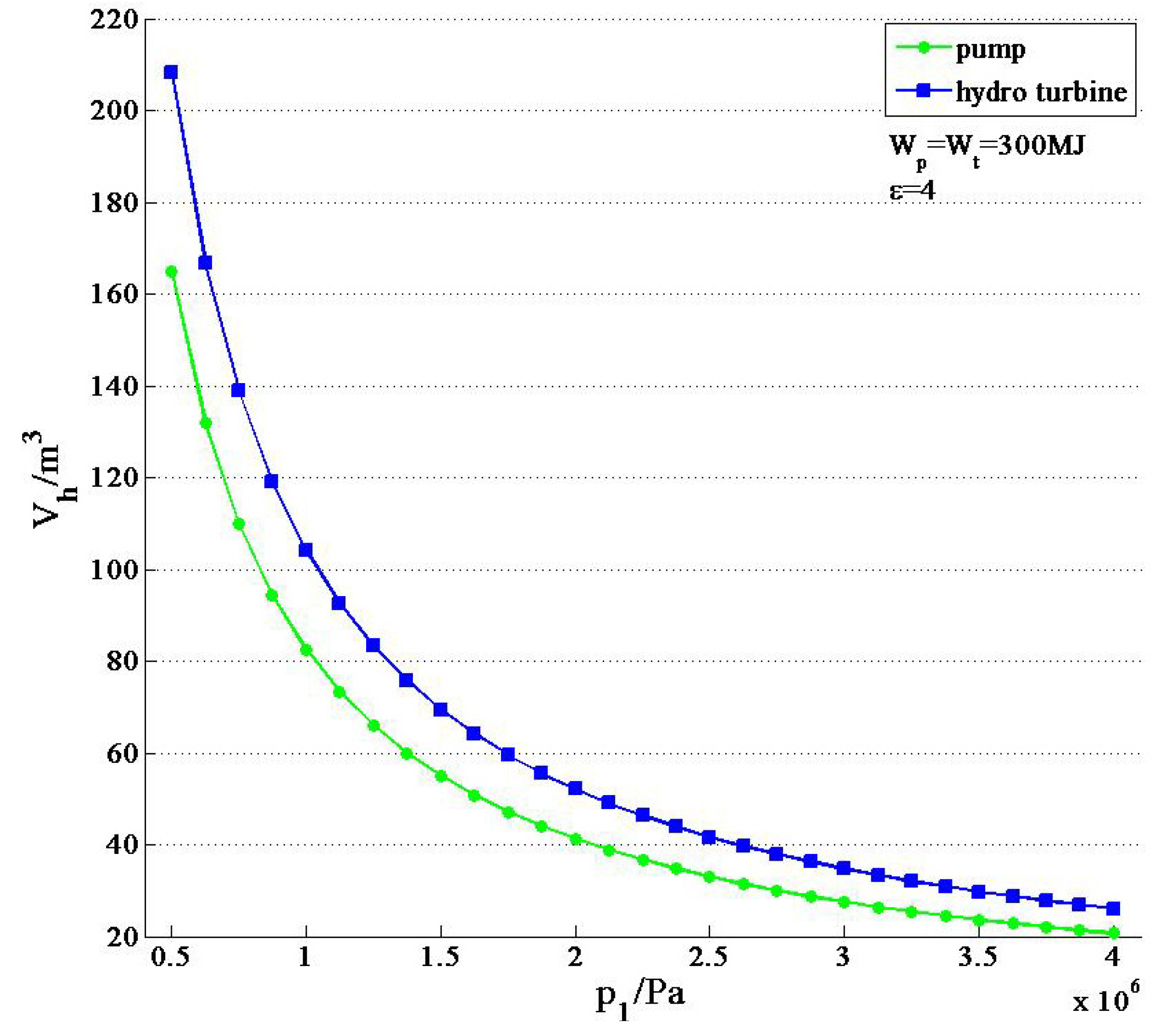
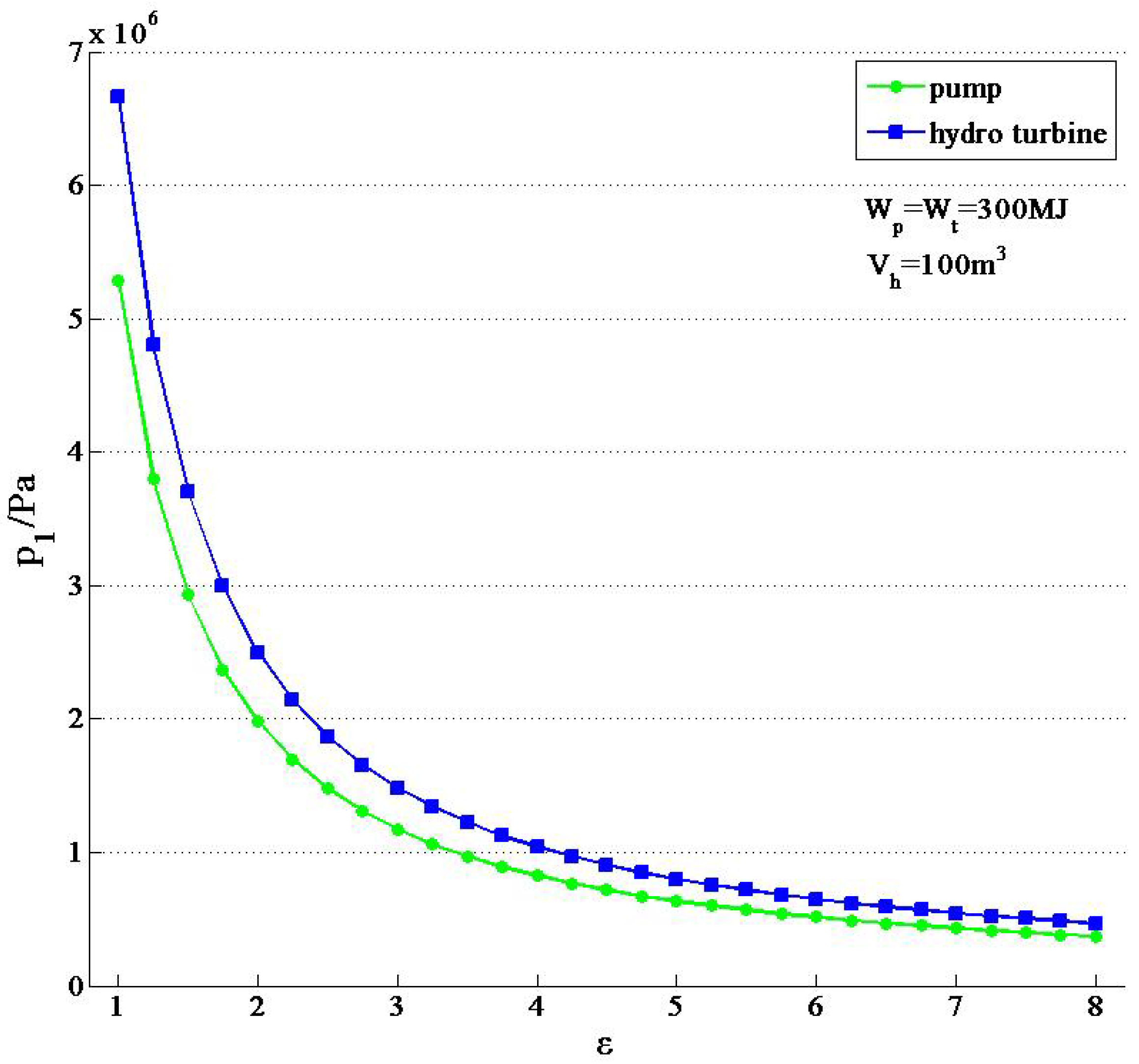
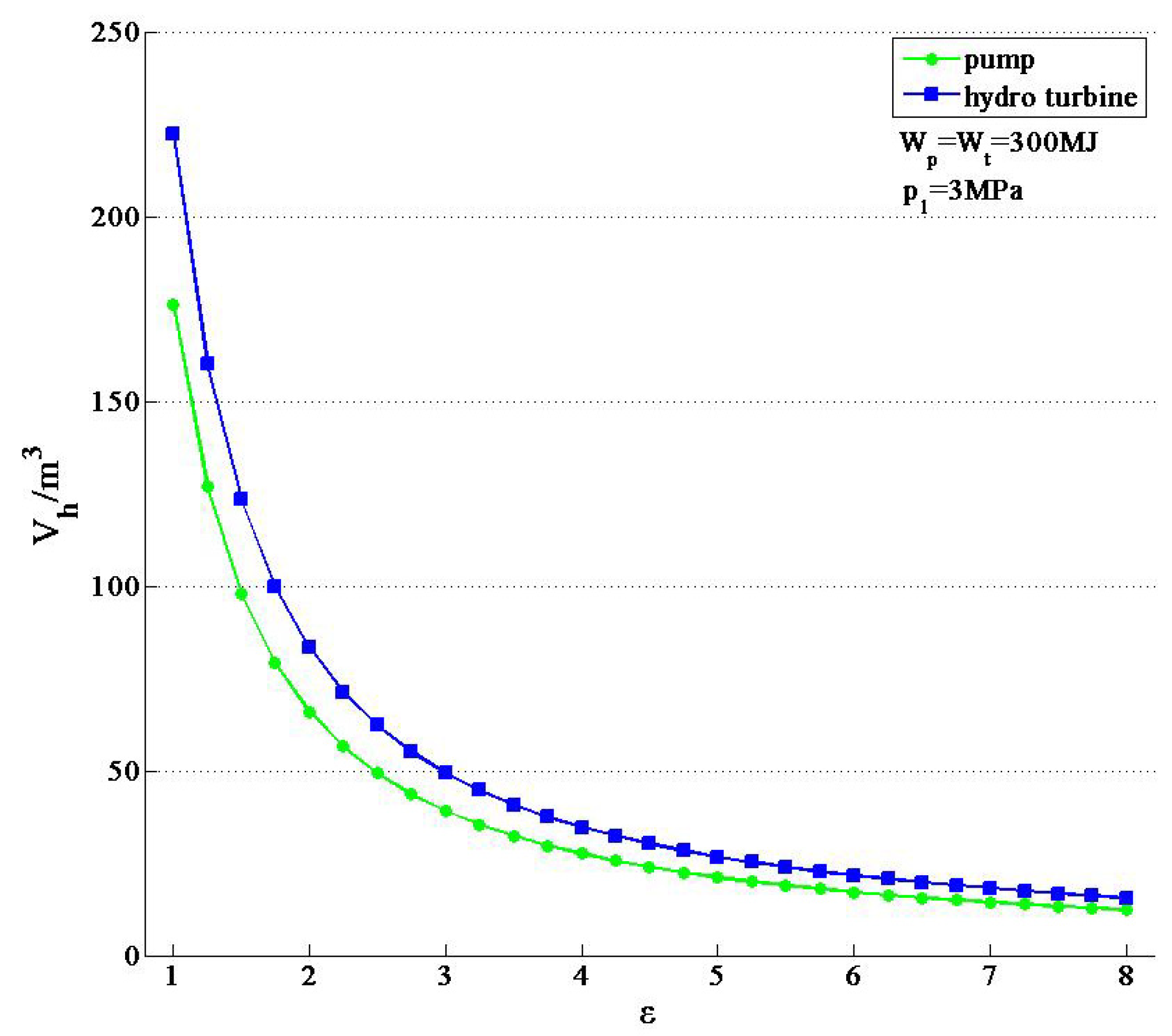
5.2. Change Relations among Preset Pressure, Vessel Volume and Water-Air Volume Ratio

The preset pressure, vessel volume, and water-air volume ratio influence each other in the condition of certain total work input and output. The following parameters are assumed: total work Wp = Wt = 300 MJ, environment pressure p0 = 0.1MPa, pump efficiency ηp = 0.88, and hydro turbine ηt = 0.9. The change relations of the three factors are shown in Figure 8, Figure 9 and Figure 10.
Figure 8. Vessel volume various with pre-set pressure.
Energies 06 01554 g008
Figure 9. Vessel volume various with water-air volume ratio.
Energies 06 01554 g009
Figure 10. Pre-set pressure various with water-air volume ratio.
Energies 06 01554 g010
It is found that any two of the preset pressure, vessel volume and water-air volume ratios have an inverse relationship, such that as one parameter increases, the other decreases. In addition, when one parameter increases to the allowed maximum value, the other decreases slowly.

5.3. Influence of Water Pump Efficiency and Water Turbine Efficiency

In the work process of the PHCA, the compressor just works for initial pressure. From Equations (15) and (16), the system efficiency are productive in both items and is listed as follows:
η = W t W p = η p η t
Therefore, system performance is proportional to both water pump efficiency and hydro turbine efficiency.

6. Conclusions

A novel mixed energy storage system, its performance, and its working principles are fully explored in this paper. A detailed thermodynamic analysis has been presented, and the results show the following:
  • The PHCA has the advantages of simple structure, high efficiency and low cost compared with the CAES, and does not need special geologic conditions like a pumped hydro storage system.
  • In the analysis above, the work density is increasing when pre-set pressure and water to air volume ratio is increasing. In addition, any two of the pre-set pressure, vessel volume, and water to air volume ratios have an inverse relationship in the condition of certain total work input and output. This result can play a guiding role in constructing a specific power system.
  • On the premise of assuming the charge and discharge as an isothermal process, the PHCA efficiency is proportional to the pump efficiency and water turbine efficiency.

Acknowledgements

This work was supported by the National High-Technology Research and Development Program (863 Program) of China (2012AA052505) and by the Chinese National Natural Science Funds (51176145).

Nomenclature

PPressure (Pa)CpSpecific heat (J K−1 kg−1)
TTemperature (K)RgGas constant (J K−1 kg−1)
VVolume (m3)mQuality (kg)
kAdiabatic index (-)εWater and air volume ratio (-)
ρDensity (kg m−3)ηEfficiency (-)
Subscripts
wWatertHydro turbine
nNitrogencCompressor
pPumpaAir

References

  1. Daneshi, A.; Sadrmomtazi, N.; Daneshi, H.; Khederzadeh, M. Wind power integrated with compressed air energy storage. In Proceedings of 2010 IEEE International Conference on Power and Energy (PECon), Kuala Lumpur, Malaysia, 29 November–1 December 2010; pp. 634–639.
  2. Cavallo, A.J. Energy storage technologies for utility scale intermittent renewable energy systems. J. Solar Energy Eng. 2001, 123, 387–389. [Google Scholar] [CrossRef]
  3. Bradshaw, D.T. Pumped hydro electric storage (PHS) and compressed air energy storage (CAES). IEEE Trans. Energy Convers. 2000, 22, 95–102. [Google Scholar]
  4. Linden, S.V. Bulk energy storage potential in the USA, current developments and future prospects. Energy 2006, 31, 3446–3457. [Google Scholar] [CrossRef]
  5. Cavallo, A. Controllable and affordable utility-scale electricity from intermit-tent wind resources and compressed air energy storage (CAES). Energy 2007, 32, 120–127. [Google Scholar] [CrossRef]
  6. Lund, H.; Salgi, G. The role of compressed air energy storage (CAES) in future sustainable energy systems. Energy Convers. Manag. 2009, 50, 1172–1179. [Google Scholar] [CrossRef]
  7. Cavallo, A. Controllable and affordable utility-scale electricity from intermittent wind resources and compressed air energy storage (CAES). Energy 2007, 32, 120–127. [Google Scholar] [CrossRef]
  8. Martínez, M.; Molina, M.G. Dynamic performance of compressed air energy storage (CAES) plant for applications in power systems. In Proceedings of IEEE/PES Transmission and Distribution and Expositon, Sao Paulo, Brazil, 8–10 November 2010; pp. 496–503.
  9. Daneshi, H.; Srivastava, A.K.; Daneshi, A. Generation scheduling with integration of wind power and compressed air energy storage. In Proceedings of 2010 IEEE PES Transmission and Distribution Conference and Exposition, New Orleans, LA, USA, 19–22 April 2010; pp. 1–6.
  10. Ibrahim, H.; Younes, R. Study and design of a hybrid wind–diesel-compressed air energy storage system for remote areas. Appl. Energy 2010, 87, 1749–1762. [Google Scholar] [CrossRef]
  11. Grazzini, G.; Milazzo, A. A thermodynamic analysis of multistage adiabatic CAES. Proc. IEEE 2012, 100, 461–472. [Google Scholar] [CrossRef]
  12. Kim, Y.M.; Favrat, D. Energy and exergy analysis of a micro-compressed air energy storage and air cycle heating and cooling system. Energy 2010, 35, 213–220. [Google Scholar] [CrossRef]
  13. Yang, C.J.; Jackson, R.B. Opportunities and barriers to pumped-hydro energy storage in the United States. Renew. Sustain. Energy. Rew. 2011, 15, 839–844. [Google Scholar] [CrossRef]
  14. Wang, Z. Thermal and Power Mechanical Basis; [in Chinese]; China Machine Press: Beijing, China, 2000. [Google Scholar]
  15. Drury, E.; Denholm, P.; Sioshansi, R. The value of compressed air energy storage in energy and reserve markets. Energy 2011, 36, 4959–4973. [Google Scholar] [CrossRef]
  16. Caralis, G.; Papantonis, D.; Zervos, A. The role of pumped storage systems towards the large scale wind integration in the Greek power supply system. Renew. Sustain. Energy Rev. 2012, 16, 2558–2565. [Google Scholar] [CrossRef]
  17. KIM, Y.M.; Shin, D.G.; Favrat, D. Operating characteristics of constant-pressure compressed air energy storage (CAES) system combined with pumped hydro storage based on energy and exergy analysis. Energy 2011, 36, 6220–6233. [Google Scholar] [CrossRef]

