Abstract
Aeroelastic instability problems have become an increasingly important issue due to the increased use of larger horizontal axis wind turbines. To maintain these large structures in a stable manner, the blade design process should include studies on the dynamic stability of the wind turbine blade. Therefore, fluid-structure interaction analyses of the large-scaled wind turbine blade were performed with a focus on dynamic stability in this study. A finite element method based on the large deflection beam theory is used for structural analysis considering the geometric nonlinearities. For the stability analysis, a proposed aerodynamic approach based on Greenberg’s extension of Theodorsen’s strip theory and blade element momentum method were employed in conjunction with a structural model. The present methods proved to be valid for estimations of the aerodynamic responses and blade behavior compared with numerical results obtained in the previous studies. Additionally, torsional stiffness effects on the dynamic stability of the wind turbine blade were investigated. It is demonstrated that the damping is considerably influenced by variations of the torsional stiffness. Also, in normal operating conditions, the destabilizing phenomena were observed to occur with low torsional stiffness.
1. Introduction
Wind energy has become one of the fastest growing renewable energy sources, because energy generated by wind power is one of the cleanest energy resources available. As horizontal axis wind turbine (HAWT) blades become lighter and more flexible, the system dynamics must be analyzed comprehensively in order to evaluate and understand the complex interaction of the elastic vibrations of the wind turbines and the unsteady aerodynamic forces acting on them. In line with the demand for lighter wind turbine blades, new advanced fabrication methods and composite materials have been introduced, and this has resulted in reduced structural damping, which is a property that until very recently was impossible to model and enhance [1]. However, abandoning geometric similarity in order to increase performance and decrease weight has led to an uncontrollable drop in aerodynamic damping [1]. For these reasons, the aeroelastic problems of wind turbine blades have a significant impact on their dynamic stability. The blade pitch-flap flutter [2,3,4,5], stall-induced vibration [6,7,8,9,10,11], rotor-shaft whirl [12,13], and aeromechanical instability [14,15] are all examples of known instabilities for rotary wings (e.g., modern wind turbines and helicopter rotors). These aeroelastic instabilities or even marginal stabilities, can lead to rapid destructive failure or limit-cycle oscillation [16]. In addition, for wind turbines, despite their similarities to the helicopter rotor problem, only a very few experimental studies have been undertaken to investigate its detailed structure [17], hence, the factors that affect the aeroelastic responses of such blades are only now being extensively studied and explored especially with regard to their dynamic stability. Moreover, because the rotational characteristics of rotor blades can cause unfavorable vibrations, it is important to understand the dynamic characteristics according to the rotational frequency. These analyses are not only aimed at estimating the aeroelastic stability but also to conduct modifications of the rotor blade structure or operational control in order to enhance the aeroelastic characteristics.
Structural modeling which use the kinematics of one-dimensional beams and considers the geometric nonlinearities, transverse shear deformation, and cross-sectional warping is required. Two major nonlinear beam models for rotary wings are widely used for structural analyses: one model is the large deflection beam theory that introduced Euler angles to construct the transformation matrix [18,19,20] and the other is the moderate deflection beam theory using ordering schemes. Because the numerical error due to the high order nonlinear terms may increase as the nonlinearities increase [21], this study demonstrates the possibility of obtaining accurate analyses using the large deflection beam theory. Also, the modification of Greenberg’s extension of Theodorsen’s theory and the blade element momentum (BEM) theory were used to predict the aerodynamic loads. In this research, the numerical responses for the dynamic stability were estimated through fluid-structure interaction simulations. As mentioned earlier, because few experimental studies for large wind turbines have been undertaken to investigate these aeroelastic characteristics, the present results were compared with previous study [22,23]. The present methods predicted the aerodynamic and structural behaviors of the large-scaled horizontal axis wind turbine blades with reasonable accuracy. It involved the effect of the steady-state blade deflections on its aeroelastic stability. Furthermore, this paper dealt with the effects of structural coupling on dynamic stability with variations of torsional stiffness.
2. Analysis
2.1. Rotor Structural Model
A wind turbine blade rotating with a constant angular velocity Ω is shown in Figure 1. The triad I1, I2, and I3 refer to a blade fixed in an inertia frame, and the triad i1, i2, and i3 refer to a blade fixed in a reference frame that rotates with respect to the inertia frame at an angular velocity ΩI3.
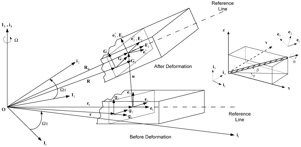
Figure 1.
Geometry and coordinate systems of a rotor blade before and after deformation.
The triad e1, e2 and e3 are attached to a reference line along the axis of the deformed blade. The geometrical nonlinearities are described using coordinate transformation matrices with Euler angles, and have the following relationship:
 where:


The transformation matrix, T represents the functions of the curvilinear axial coordinate x1; and Ψ, β, and θ indicate sweep angle, precone angle and initial pitch angle, respectively. Assuming that the initial curvatures and shearing strains are much smaller than unity in the Green-Lagrangian strain components, the strain-displacement relations are represented the same as those in the literature [24]. If higher-order strain components and initial curvatures are neglected and general warping displacements are introduced in-plane and out-of- plane of a cross-section, the strain-displacement relations can be expressed as follows [25]:
 where x1, x2, and x3 are curvilinear coordinates; and w1, w2, and w3 are the general warping displacements of an arbitrary point on the cross-section. The force strain (,
,
) and the moment strain (κ1, κ2, κ3) components are given in the literature [25]. Here, (.)' indicates the derivative with respect to x1 and (.), i denotes the derivatives with respect to xi, i = 2, 3.

The variations in the strain energy and kinetic energy of the applied forces are defined as follows:

 where
and
vectors are defined as
= {,
,
}T,
={κ1 κ2 κ3}T, respectively. In addition, the sectional stiffness matrices [], [], and [
] are 3 × 3 matrices that depend not only on the material properties, but also on cross-sectional geometry and initial curvature and twists. ρ indicates the mass density of the blade, and V is the velocity with respect to the inertia frame (V= R + ΩI3 × R). Here, the term of R is the position vector of generic point in the deformed blade, and can be expressed as follows:
 where R0 is the position vector of reference point in the deformed blade; and Ei (i = 1, 2, 3) denotes the reference base vector in the deformed blade.


In general, the HAWT blades should be aerodynamically shaped, smooth, light, dimensionally accurate and capable of sustaining a very large number of load cycles over its design life [26]. Hence, composite materials such as fiber-reinforced plastics are the favored material for rotor blades. The sectional elastic constants of the composite blade can be obtained in an unloading condition using the refined cross-sectional finite element method, that is, the equivalent one-dimensional beam sectional properties are generated from a three-dimensional blade model. Alternatively, the properties can be obtained from experimental data or open-source code such as PreComp [27].
2.2. Rotor Aerodynamic Model
2.2.1. Modification of Greenberg’s Extension of Theodorsen’s Strip Theory
The aerodynamic loads acting on the rotor blade shown in Figure 2 were obtained using a modification of Greenberg’s extension of Theodorsen’s strip theory [28] for a horizontal axis wind turbine blade undergoing unsteady motion. The blade undergoes two degrees of motion: a plunging motion h(t) and a pitching motion ε(t) about the blade elastic axis.

 where a denotes an offset between the mid-chord and elastic axis; b is blade semi-chord length; c indicates blade chord length; Vrel is the relative velocity; and the VN and VT stand for the normal and tangential velocity, respectively. Also, Cl and Cm are lift coefficient and moment coefficient, respectively. In addition,
  is the Theodorsen’s lift deficiency function [28,29], which is defined as:


 is the Theodorsen’s lift deficiency function [28,29], which is defined as:

The  (i = 0, 1) is the Hankel function of second kind of order i, and the term of Ji (i = 0, 1) is the real part of the complex Bessel function of order i, and the k is reduced frequency. To obtain a solution to non-constant free-stream for the unsteady motions as well as the airfoil at constant angle of attack, it is assumed that the wake is sinusoidal.
 (i = 0, 1) is the Hankel function of second kind of order i, and the term of Ji (i = 0, 1) is the real part of the complex Bessel function of order i, and the k is reduced frequency. To obtain a solution to non-constant free-stream for the unsteady motions as well as the airfoil at constant angle of attack, it is assumed that the wake is sinusoidal.
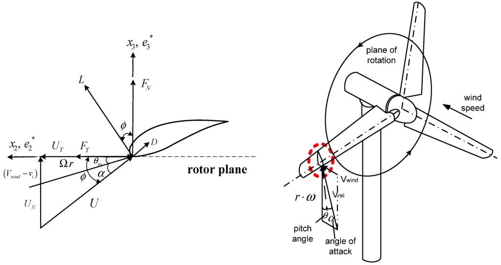
Figure 2.
Sectional aerodynamics of the wind turbine blade (modification of Greenberg’s extension of Theodorsen’s strip theory).
It is assumed that the flow around the pitch regulated wind turbine rotor is incompressible, inviscid, and remains attached to the blade. The pitching moment and aerodynamic forces in normal and tangential directions can be defined as follows:


 where D refers to the drag force acting on each of the airfoils. The term LC is the circulatory lift which is normal to the velocity; and LNC is the non-circulatory lift, which is normal to the chord line. Because the effective angle of attack on the wind turbine blade is not sufficiently small, the sin ø and cos ø can be treated as the (−UN/U) and (UT/U), respectively. After substituting each force terms into Equations (11,12) and regrouping terms, the rearranged equations can be expressed as follows:


The formulation for describing the trailed vortex at the blade tip generates a large local inflow over the tip region and realistically decreases the lifting capability over such region [30]. To simulate the large-scaled wind turbines with a finite number of blades, the tip-loss correction should be introduced and applied to this proposed aerodynamic approach. The effects of compressibility and reversal flow were also considered in the aerodynamic method.
The components of the resultant velocity, U in the deformed blade coordinate system are expressed as follows:
 where
where  (i = 1, 2, 3) is the component of elastic velocity vectors of the blade and R0i (i = 1, 2, 3) is the component of position vector; and R0i is an arbitrary point of the cross-section in the deformed blade configuration. The term r is the blade radius; Ω, the constant angular velocity; γ, the yaw angle; Ψ, the azimuth angle of the blade and Vwind, the mean wind speed. The term μ denotes the nondimensional term given by μ = Vwind/ΩR. The term λi is The inflow ratio λi denotes the inflow ratio, which is defined as a non-dimensionalized operational speed [31], and can be defined as follows:


 (i = 1, 2, 3) is the component of elastic velocity vectors of the blade and R0i (i = 1, 2, 3) is the component of position vector; and R0i is an arbitrary point of the cross-section in the deformed blade configuration. The term r is the blade radius; Ω, the constant angular velocity; γ, the yaw angle; Ψ, the azimuth angle of the blade and Vwind, the mean wind speed. The term μ denotes the nondimensional term given by μ = Vwind/ΩR. The term λi is The inflow ratio λi denotes the inflow ratio, which is defined as a non-dimensionalized operational speed [31], and can be defined as follows:

The term σ is the blade solidity, and is defined as the ratio of blade area to rotor disk area (σ = Nb·c/ 2πr, where Nb is the number of blades). The induced velocity, vi is taken to be steady and uniform along the blade radius and is set equal to the value of the inflow given by the combined momentum and the blade element theory at a radial station r = 0.75R. Finally, the virtual work done by the external forces can be obtained, and the formulation is defined as follows:
 where:


After computing the aerodynamic loads and substituting the results obtained using the proposed method into {f} term of Equation (18), the virtual work done by external forces can be employed in constructing the governing equation of motion.
2.2.2. Blade Element Momentum Method
Momentum theory refers to the control volume analysis of the forces at the blade based on the conservation of the linear and angular momentum. Blade element theory refers to an analysis of the aerodynamic loads at a section of the blade. The results of these approaches can be combined into strip theory or blade element momentum (BEM) method. The fundamental concept of the BEM is to balance the linear and angular momentum changes of the air masses flowing through the rotor disc with the axial force and torque generated on the rotor blades. This balance is performed, considering the flow through annular strips of width and the airloads on blade elements of the same width; the aerodynamic coefficients were obtained for the various airfoils from wind tunnel experiments. If the lift coefficient, Cl and drag coefficients, Cd are known, the forces normal to and tangential to the rotor plane, can be calculated as follows:


 where:
 where Cn and Ct refer to the force coefficients in normal and tangential directions, respectively and φ is the angle between the rotor plane and relative velocity, as shown in Figure 3. By substituting the Equations (20–22) into Equations (18,19), we can obtain the work done by the external force, which is used in constructing the equation of motion.


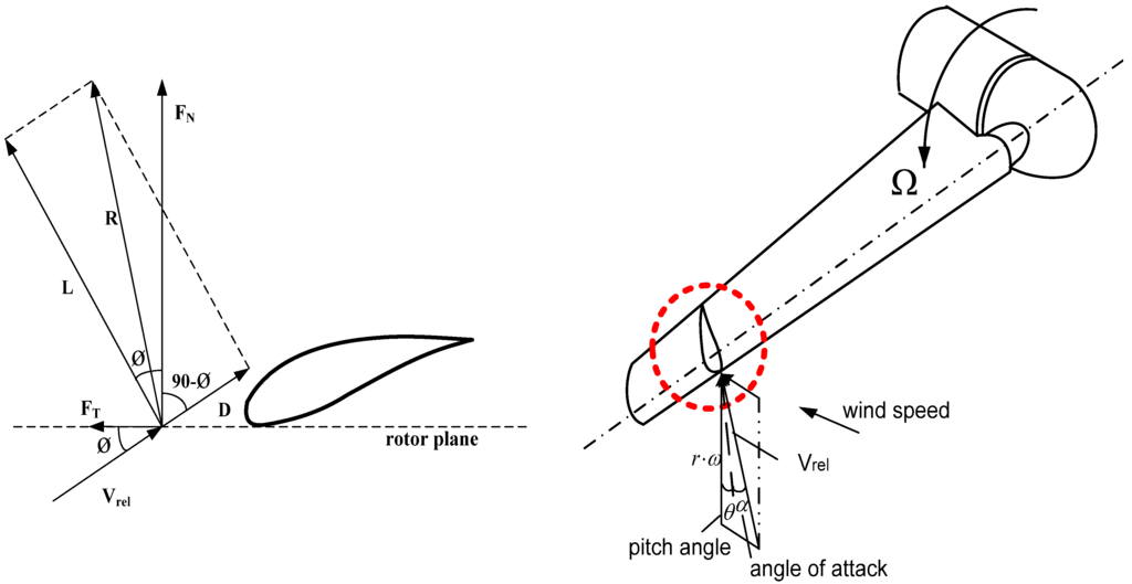
Figure 3.
The local normal and tangential loads on a wind turbine blade (BEM method).
With this BEM method, it is possible to predict the aerodynamic loads for different settings of wind speed, rotational speed and pitch angle. The induction factors for predicting the induced velocity can be expressed as follows:
 where:


The Prandtl tip-loss factor, Ftip-loss was employed to consider the effect of the discrete number of the wind turbine blades. Also, the rotational augmentation corrections for three-dimensional delayed stall were applied by using AirfoilPrep [32]. It uses the Selig and Eggars methods to modify the lift and drag coefficients on the rotating blade.
2.3. Rotor Aeroelastic Model
The process of predicting the aeroelastic responses is shown in Figure 4. The fluid-structure interaction analysis incorporates the structural model based on the nonlinear beam theory that is coupled with the aerodynamic model. For the fluid-structure interaction analysis, the equation of motion for a horizontal axis wind turbine blade can be obtained using Hamilton’s weak principle:


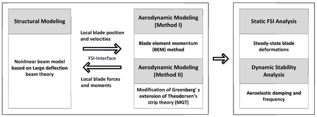
Figure 4.
Scheme of fluid-structure interaction analysis for estimating the aeroelastic responses.
Applying the standard finite element technique to Hamilton’s weak principle, Equation (26), the nonlinear finite element equations of motion in matrix form can be formulated as:
 where M(q) is the mass matrix; MA(q) is the aerodynamic apparent mass matrix; G(q) is gyroscopic damping matrix; CA(q) is the aerodynamic damping matrix in finite elements; P(q) is the internal elastic force vector; PC(q) is the centrifugal load vector; and PA(q) is the aerodynamic load vector. To solve the governing equation of motion, dropping all time-dependent terms, the nonlinear steady-state deformation is calculated using the iterative Newton-Raphson method. By assuming an equilibrium state, Equation (27) is simplified and rearranged using a Taylor series extension:
 where
where  , and
, and  are the tangential stiffness, centrifugal stiffness and tangential aerodynamic matrices, respectively. The term q is the generalized nodal displacement vector, and the equilibrium deflections can be predicted through the Newton-Raphson iterative method. Assuming that the flutter motion is a small perturbation
  about the equilibrium position q0, or q(t) = q0 +
  , then the linearization of the nonlinear finite element equations of motion can be expressed as follows:
 where K(q0) is the asymmetric tangent stiffness matrix including the internal elastic, centrifugal, and aerodynamic terms, and
  is the coupling term relevant to aerodynamic states. It is well known that modal representation is convenient for reducing a matrix size and for identifying the flutter mode. The preceding linearized flutter equations are transformed into the modal space using the expression of
  = [ø]{y(t)}, where [ø] is the modal matrix of the first m coupled rotating modes, and {y(t)} is the vector of m generalized coordinates in the modal space. Equation (27) can be rewritten by substituting
  = [ø]{y(t)} and pre-multiplied [ø]T. Therefore, the rearranged equation is expressed as follows:
 where:


 , and
, and  are the tangential stiffness, centrifugal stiffness and tangential aerodynamic matrices, respectively. The term q is the generalized nodal displacement vector, and the equilibrium deflections can be predicted through the Newton-Raphson iterative method. Assuming that the flutter motion is a small perturbation
  about the equilibrium position q0, or q(t) = q0 +
  , then the linearization of the nonlinear finite element equations of motion can be expressed as follows:

 is the coupling term relevant to aerodynamic states. It is well known that modal representation is convenient for reducing a matrix size and for identifying the flutter mode. The preceding linearized flutter equations are transformed into the modal space using the expression of
  = [ø]{y(t)}, where [ø] is the modal matrix of the first m coupled rotating modes, and {y(t)} is the vector of m generalized coordinates in the modal space. Equation (27) can be rewritten by substituting
  = [ø]{y(t)} and pre-multiplied [ø]T. Therefore, the rearranged equation is expressed as follows:


The transformed modal equations are solved through the p-k modal flutter analysis discussed in the literature [33]. The Laplace operator is p= λ + iω, where λ and ω indicate aeroelastic damping and frequency, respectively.
3. Results and Discussion
As horizontal axis wind turbine blades become lighter and more flexible, comprehensive systems dynamic analyses are required to predict the complex interaction of the elastic vibrations of the blade and the unsteady aerodynamic forces acting on them. Thus, in this study, the aeroelastic simulations of a National Research Energy Laboratory (NREL) 5 MW reference wind turbine (RWT) blade were performed to estimate the static and dynamic aeroelastic responses.
3.1. Validation for Aerodynamic Predictions and Steady-State Blade Deflections
The gross properties of the NREL 5 MW wind turbine blade are presented in Table 1; details on those given properties are also presented in Figure 5. The blade consists of the Delft University (DU) airfoil and National Advisory Committee for Aeronautics (NACA) airfoil, as depicted in Figure 6.
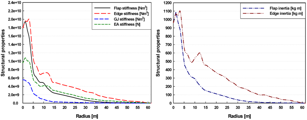
Figure 5.
Structural properties of the NREL 5 MW reference wind turbine blade.

Figure 6.
Distributed Airfoil types of the NREL 5MW reference wind turbine blade.

Table 1.
Gross properties of NREL 5 MW reference wind turbine [34].
| Parameter | Value |
|---|---|
| Rating | 5 mega-watt |
| Rotor orientation | Upwind, 3 blades |
| Rotor, Hub diameter | 126 m, 3 m |
| Cut-in, Rated, Cut-out wind speed | 3 m/s, 11.4 m/s, 25 m/s |
| Cut-in, Rated, Cut-out rotor speed | 0.722 rad/s, 1.267 rad/s, 1.267 rad/s |
The aerodynamic analysis can be divided as follows: (1) inflow computations and (2) aerodynamic loads predictions. Here, two aerodynamic approaches were used to predict the induced velocities, effective angle of attack, and airloads. The BEM method, which is most widely used in aeroelastic problems, was employed in this study. This method is a very fast and simple numerical algorithm; however, the BEM computation requires reliable airfoil data. For this reason, when an airfoil for wind turbines is newly developed, an alternative aerodynamic approach is required; thus, the modification of Greenberg’s extension of Theodorsen’s strip theory (MGT) was also employed in this study. Although the numerical approaches are quite different from the BEM method, the proposed MGT method is efficient and applicable for predicting the airloads of large-scaled wind turbines.
The aerodynamic responses of the NREL 5 MW RWT blade after applying the present two methods at all control volumes are shown in Figure 7, Figure 8 and Figure 9. The mean wind speeds were 9 m/s and 11.4 m/s, and the corresponding rotational speeds were 1.076 rad/s and 1.267 rad/s, respectively. Figure 7 shows the axial and tangential induction factors that are related to the induced velocity.
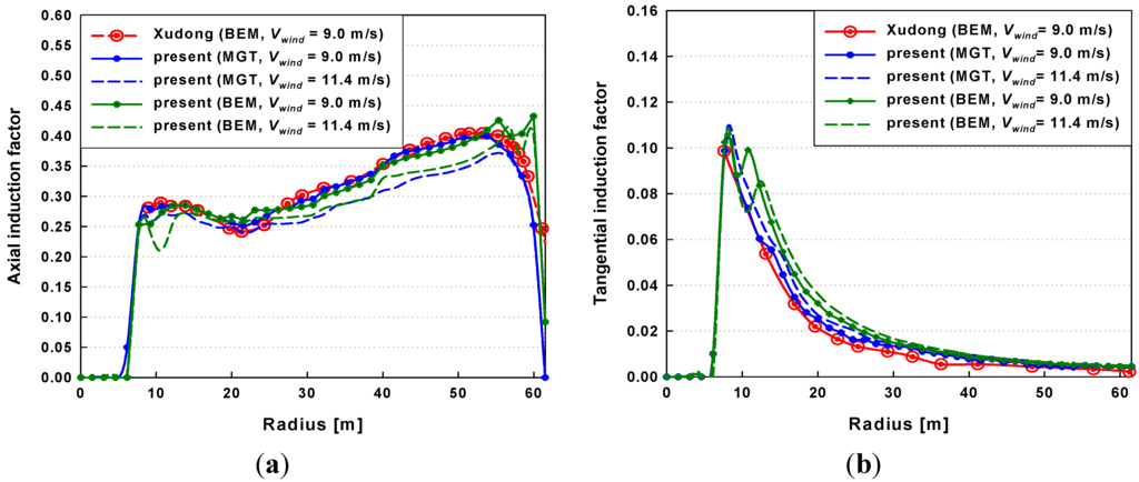
Figure 7.
Radial distributions of the induction factors at wind speeds of 9 m/s and 11.4 m/s: (a) axial induction factor; (b) tangential induction factor.
The present results are in relatively good agreement with those presented in the previously published literature [22]. However, small deviations between the present results and the BEM results of [22] were observed at the blade tip because present methods were enhanced with the Prandtl’s tip-loss correction, whereas different engineering corrections including tip-loss effect were applied in the previous study [22]. Figure 8 shows the relative velocity and effective angle of attack. The angle of attack can be computed using the combinations of blade velocity, wind speed, and calculated induced velocities. These results are in good agreement with the numerical results in the literature [22] within 5% offsets. But, some minor discrepancies of the effective angle of attack were observed near the blade tip. These deviations are caused by the differences in aerodynamic approaches for describing the tip-loss effect.
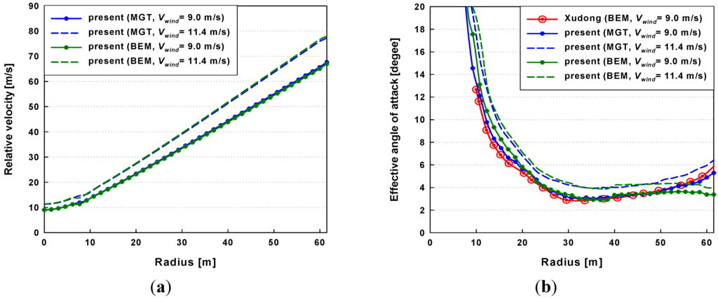
Figure 8.
Radial distributions of the relative velocity and effective angle of attack at wind speeds of 9 m/s and 11.4 m/s: (a) relative velocity; (b) effective angle of attack.
Figure 9 shows the radial distributions of the normal and tangential force. It is seen that the axial force is much larger than the tangential force. In addition, due to the usage of the tip-loss corrections, it is clearly observed that both axial and tangential forces are sharply decreased near the blade tip. Comparisons were made with the predictions of the aerodynamic forces from the results obtained using the proposed aerodynamic method and the BEM results.
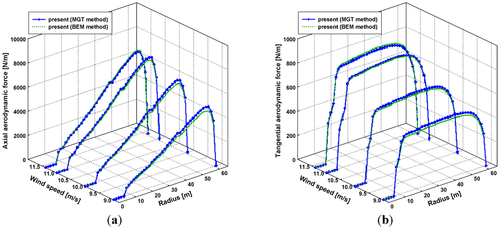
Figure 9.
Radial distributions of the aerodynamic forces at wind speeds of 9 m/s, 10 m/s, 11 m/s, and 11.4 m/s: (a) axial aerodynamic force; (b) tangential aerodynamic force.
As seen in Figure 9, the close simulation results from both aerodynamic methods were validated in this section. Moreover, fluid-structures analyses were performed to predict the steady-state blade deflections of the NREL 5 MW wind turbine model. A nonlinear beam model, including geometric nonlinearity coupled with the proposed method based on Greenberg’s extension of Theodorsen’s theory and the BEM method, was employed.
Figure 10 presents the static aeroelastic responses at a rated wind speed compared with the numerical results [22,23]. These steady-state deflections under the assumption of a constant inflow and no gravity are computed for a zero collective pitch angle. As seen in the figure, the flapwise deflections are larger than the edgewise deflections, similar to aerodynamic results as shown in Figure 9. There are minor offsets in both the flapwise and edgewise blade deflections: these distinctions were caused by differences between the present methods and the numerical approach used in [22,23] in the structural and the aerodynamic models. However, the overall responses at a rated wind speed exhibited a similar trend to the existing results in the Refs. [22,23]. Through the comparison of the numerical predictions, the present methods proved to be valid for the steady-state blade deflections.
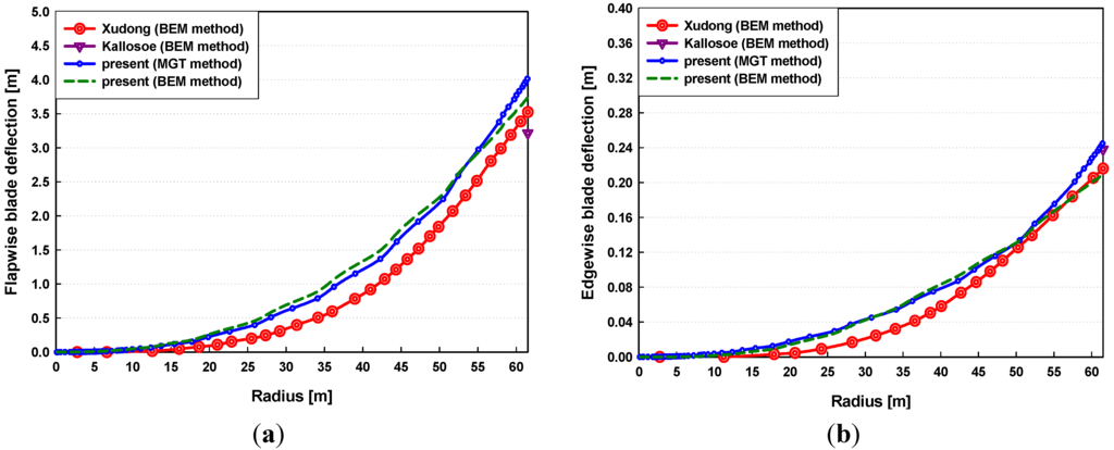
Figure 10.
Steady-state blade deflections at a rated wind speed of 11.4 m/s: (a) flapwise deflection; (b) edgewise deflection.
These numerical predictions are highly important for preventing collisions between the rotor blade and tower when MW-sized wind turbines are being developed. Also, the deflections of the blade should be estimated precisely in the design stage because highly deflected blades influence performance, such as the power production.
3.2. Dynamic Stability Analysis under Normal Operating Conditions
Because significant problems are produced in dynamic stability as the dimensions of the wind turbines increase, the aeroelastic stability analysis should be investigated. For this reason, the numerical simulations for estimating the dynamic stability of the NREL 5 MW wind turbine model were performed in this study. The stability analysis was performed using two methods of fluid-structure interaction: (1) the MGT aerodynamic method—finite element method (FEM) coupled model; and (2) the BEM method—FEM coupled model. The aeroelastic damping values, which are related to the dynamic instabilities (ex. flutter instability), were obtained through a numerical approach based on eigenvalue analysis. In addition, the proposed method proved to be valid for aeroelastic predictions in comparing between the MGT-FEM coupled model and the BEM-FEM coupled model.
A series of wind speeds (from cut-in wind speed to cut-out wind speed) and corresponding rotor speeds are presented in Figure 11.
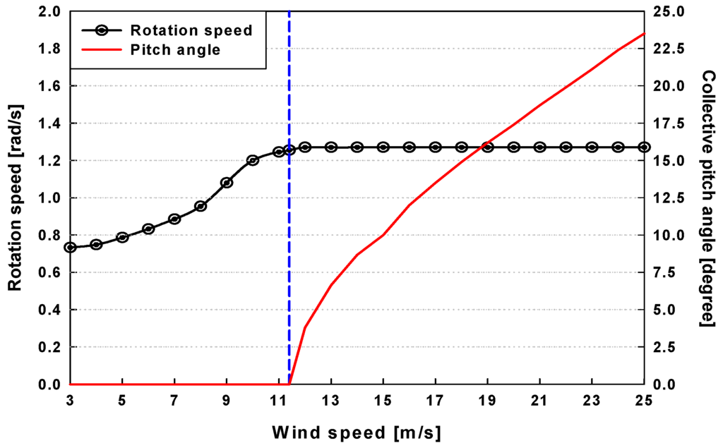
Figure 11.
Variations in wind speed versus rotor speed and collective pitch angle.
The cut-in wind speed is the minimum wind speed required to operate a wind turbine system. Also, the rated wind speed is the minimum wind speed at which the wind turbine generates its designated power. In the above rated wind speed region, pitch control is activated to maintain a constant rotation speed (or constant power extracted from the wind). To avoid structural damage to the wind turbines, the blade does not operate when the wind speed exceeds a certain magnitude, which is called the cut-out wind speed.
Because aeroelastic instabilities generally appear in low-order modes, Figure 12 and Figure 13 show the dynamic stability responses of the first four modes under normal operating conditions. Figure 12 shows the variations of the aeroelastic damping in the edgewise modes with wind speed. The deflected blades led to a change in the distributions of the aerodynamic loads, which resulted in variations of the nonlinear structural coupling effect [35]. For these reasons, the damping of the edgewise modes are significantly affected by steady-state blade deflections. The damping values of the first and second edgewise modes are increased by the rated wind speed of 11.4 m/s. However, in the active pitch control region (above the rated wind speed region), the damping decreased due to the variations of aerodynamic forces, and increased again above wind speeds of 16 m/s. The predicted damping using the MGT-FEM coupled method shows similar tendencies to those of the BEM-FEM coupled method; however, the minor differences are observed between two methods. The reason for the offsets is the difference of numerical approaches to estimate the induced velocity and airloads, which results in the variations of the aerodynamic stiffness. Figure 13 shows the variations of the aeroelastic damping in different flapwise modes with wind speed. The damping values of both the first and second flapwise modes remained almost constant because the damping for the flapwise modes was not significantly influenced by the blade deformations. The numerical results using the MGT-FEM coupled method were compared with those of the BEM-FEM coupled method, and the damping results demonstrated reasonable agreement for the first and second flap modes. As seen in the figures, it was clearly observed that the flapwise modes are highly damped for all investigated wind speeds. The aeroelastic damping implies a negative damping or stability; thus, it can be concluded that the NREL 5 MW turbine blade is considered aeroelastically stable because both the flapwise and edgewise modes are negatively damped with the wind speed.
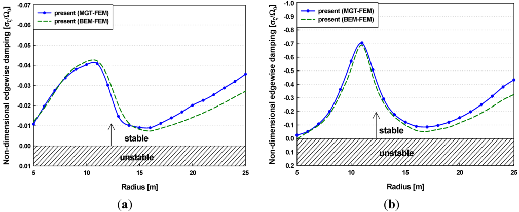
Figure 12.
Variations in the non-dimensional edgewise damping with wind speed: (a) first edgewise mode (2nd mode); (b) second edgewise mode (4th mode).
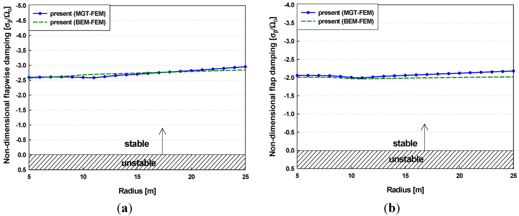
Figure 13.
Variations in the non-dimensional flapwise damping with wind speed: (a) first flapwise mode (1st mode); (b) second flapwise mode (3rd mode).
3.3. Effects of Torsional Stiffness Reductions on Dynamic Stability
Dynamic instability phenomena involving the interaction of flapwise and torsional blade vibrations cause very high amplitude blade deflection. In general, a low torsional stiffness of the wind turbine blade significantly influences a risk of flutter instability; thus, dynamic instability can arise from a reduction in the torsional stiffness [36].
This study dealt with the torsional stiffness effects on the dynamic stability of the NREL 5 MW wind turbine blade. It was assumed that the torsional stiffness is reduced uniformly from 100% (original torsional stiffness) to 20% along the blade span direction. The variations in the natural frequencies of the turbine blade with torsional stiffness reduction are shown in Figure 14. The natural frequency of the torsion mode was considerably decreased due to the reduction of the torsional stiffness. The frequencies of the 2nd/3rd flapwise and 2nd edgewise modes were slightly changed because both the flapwise and edgewise modes are coupled with the torsion mode, whereas the frequencies of the 1st flapwise and 1st edgewise modes remained almost constant.
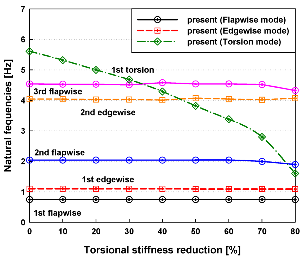
Figure 14.
Variation in natural frequencies with torsional stiffness reduction.
The stability analyses of the blade with torsional stiffness reductions were implemented at three specific wind speeds (cut-in, rated, and cut-out wind speeds). Figure 15 presents the aeroelastic damping at the cut-in wind speed of 3 m/s.
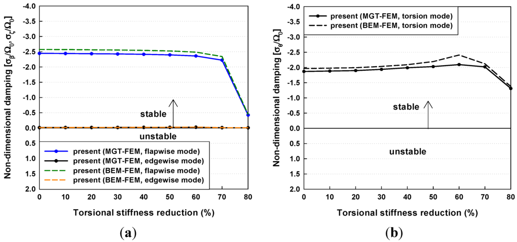
Figure 15.
Aeroelastic damping with torsional stiffness reductions at the cut-in wind speed of 3 m/s: (a) flapwise and edgewise modes; (b) torsion mode.
It is seen that the flapwise and torsion modes were highly damped under these operating conditions. The edgewise damping for all modes remained constant regardless of the torsional stiffness reductions. The flapwise and torsion damping also remained constant and were sharply decreased above a torsional stiffness reduction of 70%. It is seen that the low torsional stiffness at the cut-in wind speed does not result in any dynamic instabilities because there is only negative damping. Figure 16 shows the aeroelastic damping at the rated wind speed of 11.4 m/s. The damping values for all modes have similar tendencies to those at a cut-in wind speed. However, in flapwise damping above the torsional stiffness reduction of 60%, there was positive damping in which destabilizing phenomenon occurred.
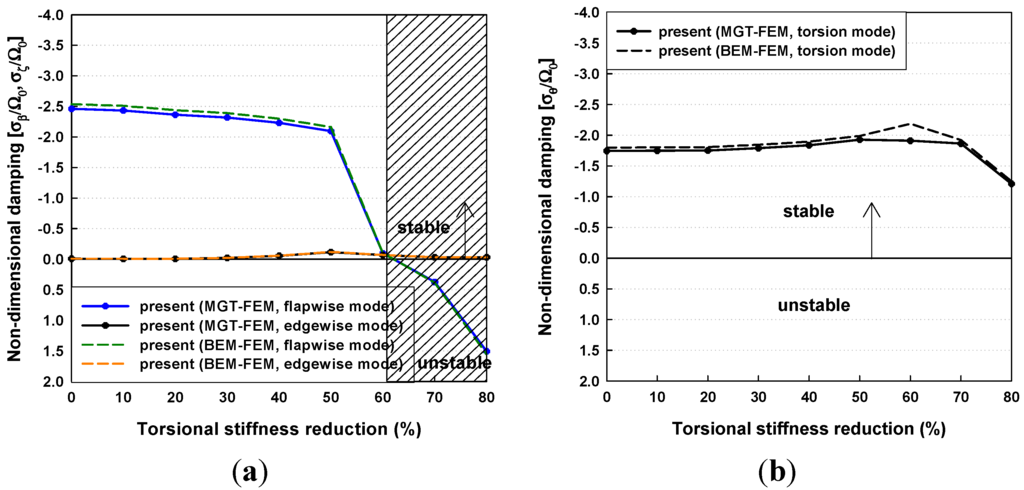
Figure 16.
Aeroelastic damping with torsional stiffness reductions at the rated wind speed of 11.4 m/s: (a) flapwise and edgewise modes; (b) torsion mode.
The aeroelastic damping at the cut-out wind speed of 25 m/s is shown in Figure 17, and this had trends similar to the predicted damping at the rated wind speed. The flapwise mode was positively damped above the torsional stiffness reduction of 70%, where the blade is destabilizing. Therefore, it can be concluded that the NREL 5MW wind turbine blade should have at least 40% of the original torsional stiffness applied to prevent dynamic instability under normal operating conditions.
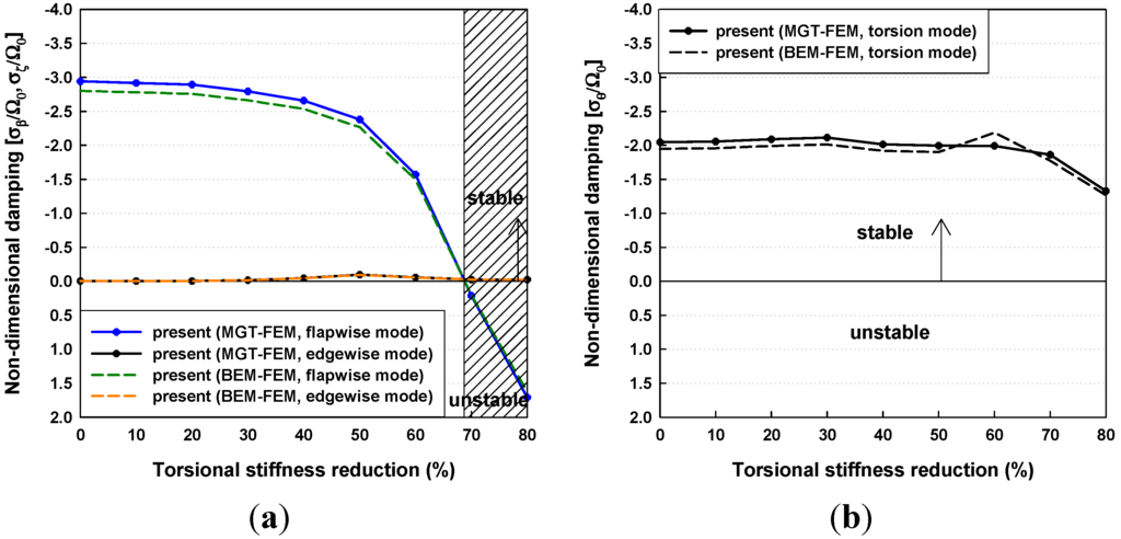
Figure 17.
Aeroelastic damping with torsional stiffness reductions at the cut-out wind speed of 25 m/s: (a) flapwise and edgewise modes; (b) torsion mode.
4. Conclusions
Numerical simulations for estimating the aerodynamic and aeroelastic responses of large-scale horizontal axis wind turbine blades were implemented in this study. The nonlinear beam model considering the geometric structural nonlinearity was employed for a one-dimensional global beam analysis that undergoes arbitrary large deflections and rotations, and the modification of Greenberg’s extension of Theodorsen’s strip theory and the BEM method were used for the fluid-structure interaction analysis. The proposed method developed for predicting the airloads was adapted for use with the wind turbines and proved to be valid for aerodynamic responses under normal operating conditions. Also, it is seen that the present results of the steady-state blade deflections correlated well with the numerical results obtained in the previous studies.
Moreover, this paper dealt with the effects of the structural coupling on the dynamic stability of the flapwise, edgewise, and torsion modes for various torsional stiffness reductions. It was found that dynamic stability was influenced by variations of the torsional stiffness. The wind turbine blade is stabilizing at the cut-in wind speed of 3 m/s; however, destabilizing phenomena at the rated wind speed of 11.4 m/s and cut-out wind speed of 25 m/s occurred with low torsional stiffness. Therefore, it can be concluded that the present numerical predictions can suggest a method for selecting light weight blades insofar as the large-scaled horizontal axis wind turbine blades are stabilizing.
Acknowledgments
This research was supported by WCU (World Class University) program through the National Research Foundation of Korea funded by the Ministry of Education, Science and Technology (R31-2008-000-10045-0). The authors are grateful for this support.
References
- Riziotis, V.A.; Voutsinas, S.G.; Politis, E.S.; Chaviaropoulos, P.K. Aeroelastic stability of wind turbines: The problems, the methods and the issues. Wind Energy 2004, 7, 373–392. [Google Scholar] [CrossRef]
- Fung, Y.C. An Introduction to the Theory of Aeroelasticity; Dover Publications: New York, NY, USA, 2002. [Google Scholar]
- Bisplinghoff, R.L.; Ashley, H.; Halfman, R.L. Aeroelasticity; Dover Publications: New York, NY, USA, 1955. [Google Scholar]
- Lobitz, D.W. Aeroelastic stability predictions for a MW-sized blade. Wind Energy 2004, 7, 211–224. [Google Scholar] [CrossRef]
- Lobitz, D.W. Parameter sensitivities affecting the flutter speed of a MW-sized blade. J. Solar Energy Eng. Trans. ASME 2005, 127, 538–543. [Google Scholar] [CrossRef]
- Peterson, J.T.; Madsen, H.A. Prediction of Dynamic Loads and Induced Vibration in Stall; Technical Report Risø-R-1045; Risø National Laboratory: Roskilde, Denmark, 1998. [Google Scholar]
- Thomsen, K.; Petersen, J.T.; Nim, E.; Øye, S.; Petersen, B. A method for determination of damping for edgewise blade vibrations. Wind Energy 2001, 3, 233–246. [Google Scholar] [CrossRef]
- Rasmussen, F.; Petersen, J.T.; Madsen, H.A. Dynamic stall and aerodynamic damping. ASME J. Sol. Energy Eng. 1999, 121, 150–155. [Google Scholar] [CrossRef]
- Chaviaropoulos, P.K. Flap/lead-lag aeroelastic stability of wind turbine blades. Wind Energy 2001, 4, 183–200. [Google Scholar] [CrossRef]
- Björck, A.; Dahlberg, J.; Östman, A.; Ganander, H. Computations of Aerodynamic Damping for Blade Vibrations in Stall. In Proceedings of the 1997 European Wind Energy Conference, Dublin Castle, Ireland, 6–9 October 1997.
- Holierhoek, J.G. Investigation into the Possibility of Flap-Lag-Stall Flutter. In Proceedings of the 45th AIAA Aerospace Sciences Meeting and Exhibit, Reno, NV, USA, 8–11 January 2007.
- Acree, C.W., Jr.; Peyran, R.J.; Johnson, W. Rotor Design for Whirl Flutter: An Examination of Options for Improving Tiltrotor Aeroelastic Margins. In Proceedings of American Helicopter Society 55th Annual Forum, Montreal, Canada, 25–27 May 1999.
- Nixon, M.W. Parametric studies for tiltrotor aeroelastic stability in high speed flight. J. Am. Helicopter Soc. 1993, 38, 71–79. [Google Scholar] [CrossRef]
- Bir, G.S.; Chopra, I. Aeromechanical instability of rotorcraft with advanced geometry blades. J. Math. Comp. Model. 1994, 19, 159–191. [Google Scholar] [CrossRef]
- Bir, G.S.; Wright, A.D.; Butterfield, C.P. Stability Analysis of A Variable-Speed Wind Turbines. In Proceedings of the 1997 ASME Wind Energy Symposium, Reno, NV, USA, 6–9 January 1997.
- Bir, G.; Jonkman, J. Aeroelastic instabilities of large offshore and onshore wind turbines. J. Phys. Conf. Ser. 2007, 75, 1–19. [Google Scholar] [CrossRef]
- Gupta, S. Development of A Time-Accurate Viscous Lagrangian Vortex Wake Model for Wind Turbine Applications. PhD Thesis, University of Maryland, College Park, MD, USA, 2006. [Google Scholar]
- Hodges, D.H. Nonlinear Equations for the Dynamics of Pre-Twisted Beams Undergoing Small Strains and Large Rotations; Technical Report TP-240; National Aeronautics and Space Administration: Washington, DC, USA, 1985. [Google Scholar]
- Bauchau, O.A.; Hong, C.H. Finite element approach to rotor blade modeling. J. Am. Helicopter Soc. 1987, 32, 60–67. [Google Scholar] [CrossRef]
- Bauchau, O.A.; Hong, C.H. Nonlinear composite beam theory. ASME J. Appl. Mech. 1988, 55, 156–163. [Google Scholar] [CrossRef]
- Panda, B. Assembly of moderate-rotation finite elements used in helicopter rotor dynamics. J. Am. Helicopter Soc. 1987, 32, 63–69. [Google Scholar] [CrossRef]
- Xudong, W.; Shen, W.Z.; Zhu, W.J.; Sørensen, J.N. Shape optimization of wind turbine blades. Wind Energy 2009, 12, 781–803. [Google Scholar] [CrossRef]
- Kallesøe, B.S.; Hansen, M.H. Effects of Large Bending Deflections on Blade Flutter Limits; Risø National Laboratory: Roskilde, Denmark, 2008. [Google Scholar]
- Stemple, A.D.; Lee, S.W. Large Deflection Static and Dynamic Finite Element Analyses of Composite Beams with Arbitrary Cross Sectional Warping. In Proceedings of 30th AIAA/ASME/ASCE/AHS/ACS Structures. Structural Dynamics and Materials Conference, Mobil, AL, USA, 3–5 April 1989; pp. 1788–1798.
- Cho, M.H.; Lee, I. Aeroelastic stability of hingeless rotor blade in hover using large deflection theory. Am. Inst. Aeronaut. Austronaut. J. 1994, 32, 1472–1477. [Google Scholar] [CrossRef]
- Det Norske Veritas (DNV) and Risø National Laboratory. In Guidelines for Design of Wind Turbines; DNV/Risø in Technical Co-Operation: Roskilde, Denmark, 2001.
- NWTC Design Codes (PreComp by Gunjit Bir). Available online: http://wind.nrel.gov/designcodes/preprocessors/precomp/ (accessed on 22 January 2011).
- Greenberg, J.M. Airfoil in Sinusoidal Motion in a Pulsating Stream; TN-1326; National Advisory Committee for Aeronautics (NACA): Washington, DC, USA, 1947. [Google Scholar]
- Loewy, R.G. A two-dimensional approach to the unsteady aerodynamics of rotary wings. J. Aeronaut. Sci. 1957, 24, 82–98. [Google Scholar]
- Leishman, J.G. Principles of Helicopter Aerodynamics; Cambridge University Press: New York, NY, USA, 2006. [Google Scholar]
- Vity, V.; Coppotelli, G.; de Pompeis, F.; Marzocca, P. Development of An Aerodynamic and Aeroelastic Tool for Wind Turbine Design. In Proceedings of the 48th AIAA/ASME/ASCE/AHS/ASC Structures, Structure Dynamics, and Material Conference, Honolulu, HI, USA, 23–26 April 2007.
- National Renewable Energy Laboratory. Computer-aided engineering tools. Available online: http://wind.nrel.gov/designcodes/preprocessors/airfoilprep/ (accessed on 13 January 2013).
- Yamane, T.; Friedmann, P.P. Aeroelastic tailoring analysis for preliminary design of advanced turbo propellers with composite blades. Comp. Fluids 1993, 21, 235–245. [Google Scholar] [CrossRef]
- Jonkman, J.; Butterfield, S.; Musial, W.; Scott, G. Definition of 5-MW Reference Wind Turbine for Offshore System Development; Technical Report NREL/TP-500–38060; National Renewable Energy Laboratory: Denver, CO, USA, 2009. [Google Scholar]
- Kallosøe, B.S. Effect of steady deflections on the aeroelastic stability of a turbine blade. Wind Energy 2011, 14, 209–224. [Google Scholar] [CrossRef]
- Buhl, T.; Markou, H.; Hansen, H.; Thomsen, K.; Rasmussen, F. Aeroelastic Stability Analysis and Passive Instability Suppression. In Proceedings of the 2006 European Wind Energy Conference and Exhibition, Athens, Greece, 27 February–2 March 2006.
© 2013 by the authors; licensee MDPI, Basel, Switzerland. This article is an open access article distributed under the terms and conditions of the Creative Commons Attribution license (http://creativecommons.org/licenses/by/3.0/).