1. Introduction
Wind turbine technology has developed rapidly over the past decade into one of the most mature renewable power generation technologies. Compared to other wind turbine systems used for commercial power generation, the accelerated evolution of the direct-driven wind turbine (WT) with a permanent magnet synchronous generator (D-PMSG) can be attributed to its simple structure, low cost of maintenance, high conversion efficiency and high reliability [
1]. Moreover, its decoupling control performance is much less sensitive to the parameter variations of the generator. Therefore, a high-performance variable-speed generation including high efficiency and high controllability is expected by using a PMSG for a wind generation system. The continuously growing penetration of wind power into the power grid has impacted power grid stability and power quality with increasing prominence. New grid codes [
2,
3] specify that grid-connected WTs must possess low voltage ride through (LVRT) capability. With this capability, the WT system can remain connected to the grid when the voltage at the point of common coupling (PCC) drops during a power grid fault and can even provide reactive power to the power grid to support grid voltage recovery until the power grid returns to normal.
At the moment, substantial documentation exists on modeling and control issues for the PMSG wind turbine [
4,
5,
6,
7]. To improve the LVRT of a direct-driven WT system, several solutions using hardware devices have been proposed in the literature [
8,
9,
10,
11]; these devices include DC choppers, energy storage systems (ESSs), static VAR compensators (SVCs), dynamic voltage restorers (DVRs) and static synchronous compensators (STATCOMs). However, the use of these devices can significantly increase system costs. Studies investigating the control strategies for direct-driven WT systems have improved the LVRT capability of these systems [
12,
13,
14,
15]. However, various issues, such as the limited reactive power support for the power grid resulting from a limited current capacity of the grid-side converter (GSC), still remain. Moreover, it is impossible to suppress the distortion of the current injected into the grid.
On the other hand, the extensive use of power electronic devices, nonlinear loads, and single-phase loads in the distribution network result in increasingly serious power quality problems, such as current harmonics and three-phase voltage imbalances, among other concerns. Therefore, centralized electric power quality control devices, such as active power filters (APFs) [
16], DVRs [
17] and SVCs [
18], are often installed in the distribution network to improve the power quality of the power grid.
In this paper, a new D-PMSG configuration is proposed for small- and medium-capacity wind turbine system in microgrid connected to the distribution network, by adding an auxiliary converter in parallel with the grid-side converter (GSC); this novel system resembles the structure and operating principles of a grid-connected converter for a direct-driven PMSG WT system and an APF. During normal operation of the power grid, the auxiliary GSC function as an APF, suppressing current harmonics and compensating reactive power to improve the grid power quality. When the grid voltage dips during a grid fault, a hierarchical coordinated control strategy can be implemented through the communications among the generator-side converter, the main GSC and the auxiliary GSC to enhance the LVRT capability; supplementary measures, such as DC unloading circuit, also can be implemented to meet the LVRT requirements imposed by grid codes. In the proposed PMSG-based WT configuration with an auxiliary GSC, various elements, such as the reactive and harmonic current compensation, LVRT and other functions, can subsequently be functionally integrated within the same system. Therefore, this scheme cannot only enhance the LVRT capability of the wind turbine system but also improve the power quality of the power grid with relatively low cost.
The paper is organized as follows:
Section 2 presents a detailed description of the PMSG WT configuration with a parallel auxiliary GSC.
Section 3 presents the control of converters under grid normal conditions.
Section 4 proposes the coordinated LVRT control scheme during grid faults.
Section 5 presents a case study using MATLAB/Simulink. The simulation results demonstrate the feasibility and effectiveness of the proposed topology and control strategy.
Section 6 concludes the analysis.
2. PMSG WT Configuration with a Parallel Auxiliary GSC
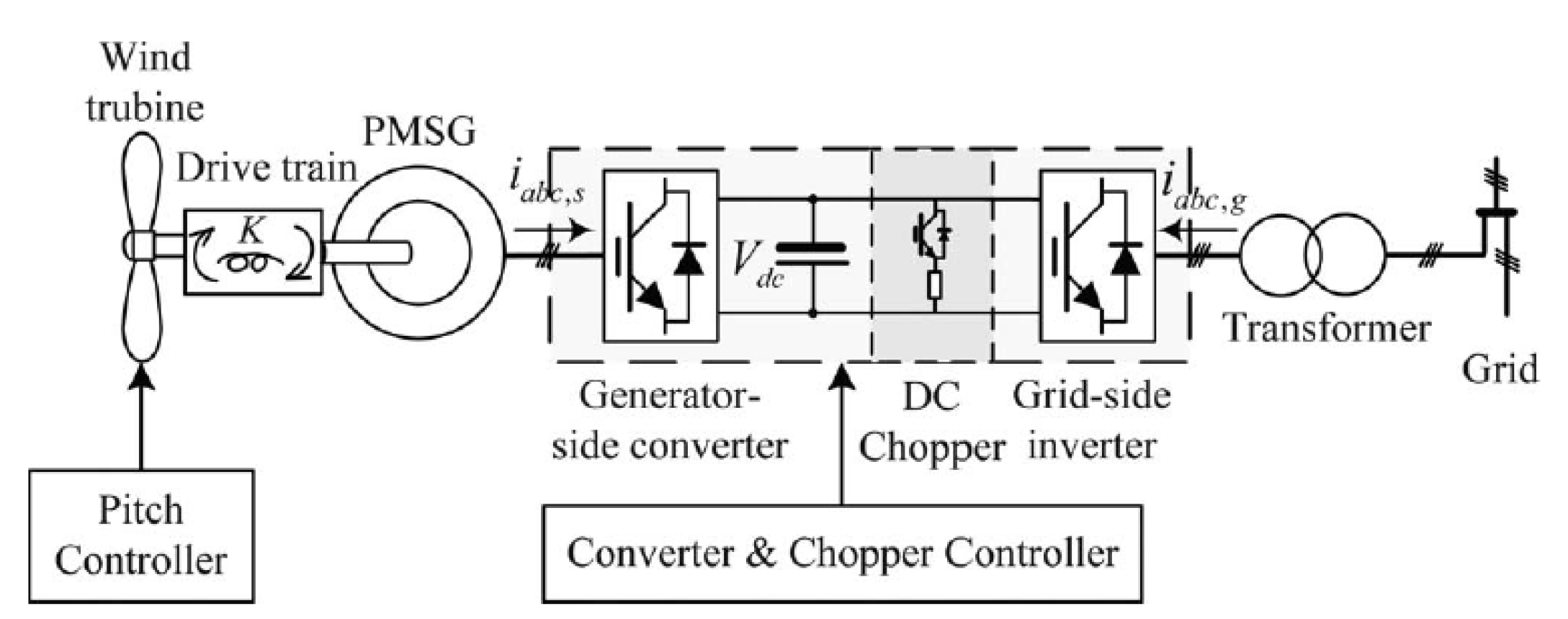
The typical structure of a direct-driven PMSG WT system is shown in
Figure 1. The stator winding of the synchronous generator is connected to the grid through a fully rated back-to-back converter. Typically, the generator-side converter controls the active and reactive power output of the PMSG. In contrast, the GSC maintains the DC-link voltage and controls the reactive power exchange between the generator and the grid,
i.e., the GSC transfers the active power extracted from the wind turbine to the grid at an adjustable power factor. The DC chopper circuit, which consists of power electronic devices and unloading resistors connected in series, is used to maintain a stable DC-link voltage during power grid faults.
Figure 1.
Direct-driven PMSG-based WT system.
Figure 1.
Direct-driven PMSG-based WT system.
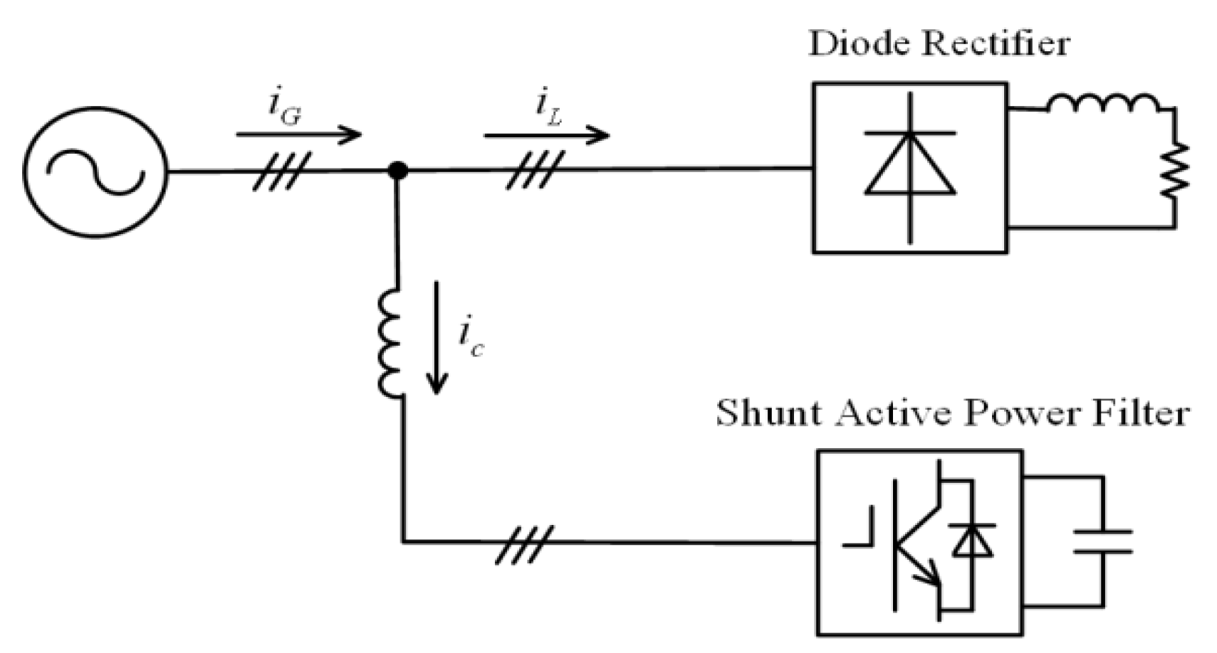
Figure 2 shows the typical structure of a shunt APF, which includes a converter, a DC-link capacitor and a filter inductor.
Figure 2.
A schematic of a typical parallel APF.
Figure 2.
A schematic of a typical parallel APF.
The APF suppresses harmonics current and compensates for reactive power by generating a compensation current with the same amplitude but the opposite phase as the harmonics current and the required reactive current; this compensation current is then injected into the power grid, thereby eliminating the original distortion and improving the power quality on the connected power grid.
Many similarities in the control mechanisms of these two systems are readily apparent: for example, a stable DC-link voltage is required to control the grid-connected PWSG WTs and to ensure effective compensation by an APF. The DC-link voltage is usually stabilized by regulating the active exchange between the AC side and the DC side of a system. When the DC-link voltage exceeds the reference value, the converter injects active power into the power grid to reduce the DC-link voltage.
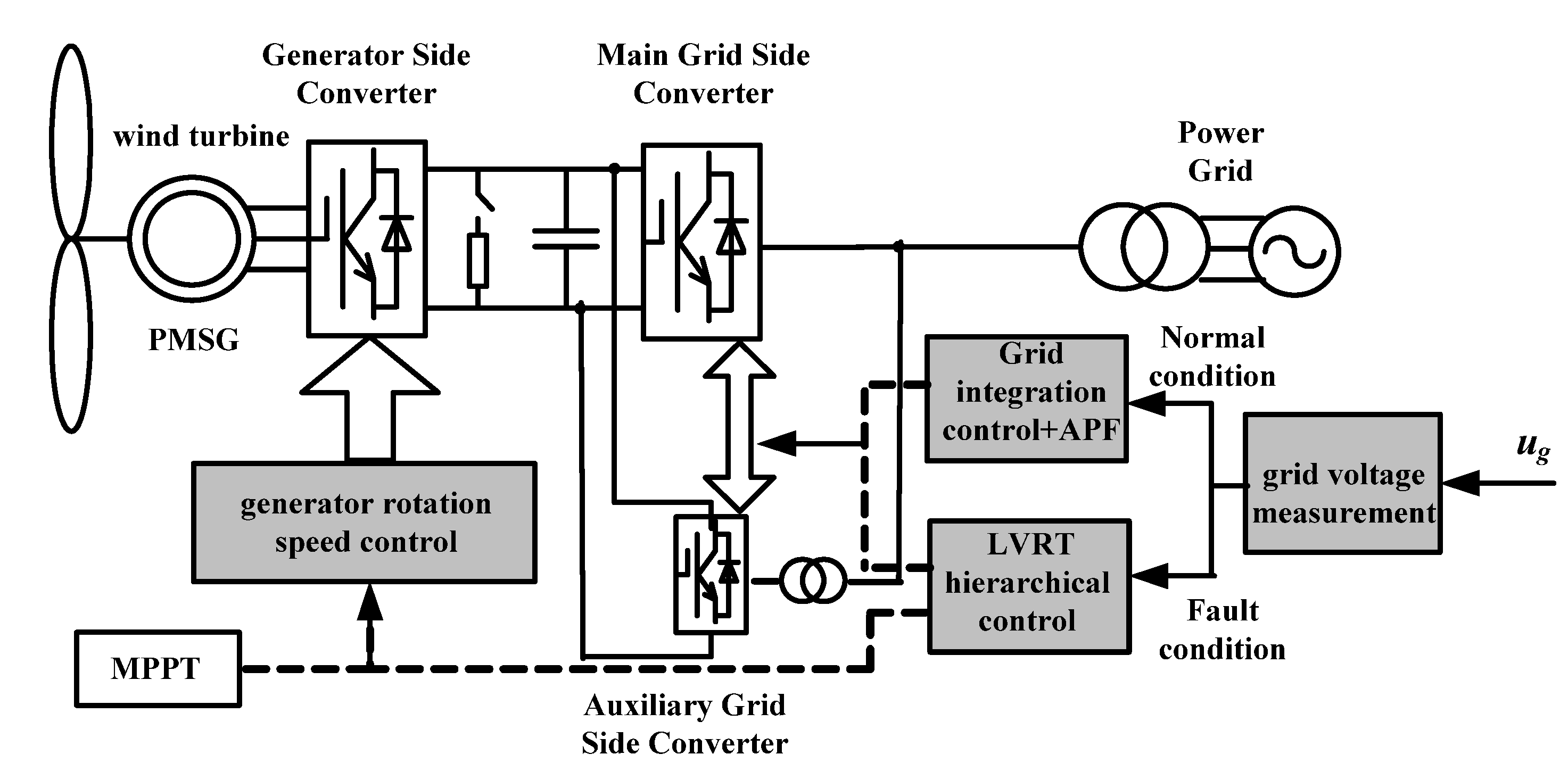
These similarities were used to develop a new topology for a direct-driven WT system, which is shown in
Figure 3. In the proposed configuration, an auxiliary converter with a half capacity of the GSC, which shares the DC-link of the back-to-back converters, is connected in parallel with the GSC in a conventional PMSG WT system.
Figure 3.
A direct-driven PMSG-based WT system with an auxiliary GSC.
Figure 3.
A direct-driven PMSG-based WT system with an auxiliary GSC.
Under normal conditions, the generator-side converter regulates the generator rotation speed by controlling the electromagnetic torque to achieve maximum power point tracking. Meanwhile, the main GSC maintains the DC-link voltage to be constant, whereas the auxiliary GSC functions as an APF to implement harmonic current compensation. During the grid voltage dips, by switching the control strategy, the generator-side converter, the GSC and the auxiliary GSC are coordinately controlled to output required active and reactive powers that follow pre-established criteria; this process of hierarchical coordinated control maintains a stable DC-link voltage and provides reactive power support to the power grid to satisfy the LVRT requirements of the grid code.
The main GSC with LC output filter only transfers fundamental power and does not provide harmonics filtering within the control bandwidth, whereas the auxiliary GSC with L output filter compensates harmonics. Hence, according to the parameters of the output filter, the cutoff frequency of the current controllers for the main GSC is designed to be approximate 200 Hz, whereas, to extract up to the 25th harmonics, the cutoff frequency of the current controller for the auxiliary GSC is designed to be 1.28 kHz, which is one tenth of the sampling frequency.
Theoretically, the larger the capacity of the auxiliary GSC, the better the performances of the harmonics filtering and LVRT capability. However, the large capacity will increase the costs of the system. Hence, considering the tradeoff between the costs and performances, the auxiliary GSC is designed to be a half capacity of the main GSC.
3. Converter Control under Normal Conditions
3.1. Generator-Side Converter Control
For the generator side, the voltage Equations of the PMSG can be expressed in the synchronous
d-q reference frame as [
19]:
where
usd and
usq are the
d-; and
q-axis stator voltage components;
isd and
isq are the
d-; and
q-axis stator current components, respectively; and
Ls,
Rs are the stator inductance and resistance, respectively.
λm is the flux; and
ωr is the rotor electrical angular speed.
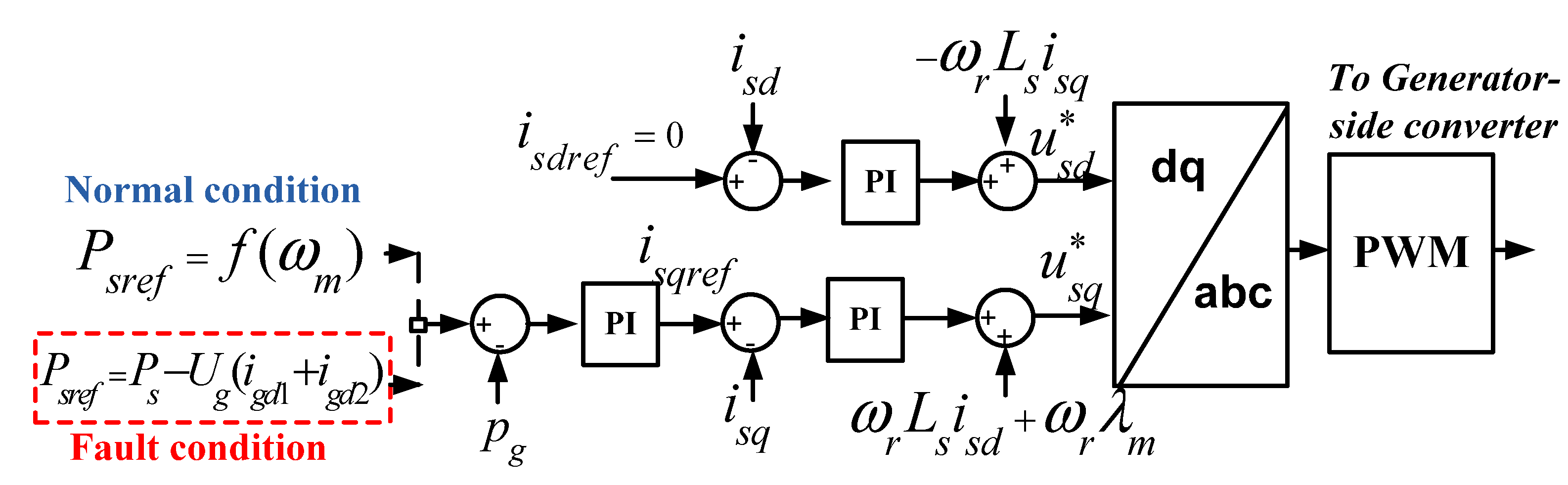
The generator-side converter controls the rotor speed of the PMSG to achieve variable-speed operation with the maximum power point tracking (MPPT) control. A cascaded control structure with an inner current control loop and an outer power control loop is employed, as shown in
Figure 4.
Figure 4.
A control diagram of a generator-side converter.
Figure 4.
A control diagram of a generator-side converter.
In order to obtain the maximum torque at the minimum current and therefore to minimize the resistive losses in the generator, the
d-axis current reference is set to zero [
20], whereas the
q-axis current reference is determined by the power controller. When the wind speed changes, the generator-side converter controls the
q-axis component of the stator current, which regulates the electromagnetic torque of the generator; thus, the turbine rotation speed is adjusted to ensure that operations remain at an optimum tip speed ratio, which corresponds to the maximum power extracted by the wind turbine.
In normal conditions, to achieve the MPPT through real-time tracking of the WT maximum wind power curve, the active power reference of PMSG wind turbine is set according to Equation (2):
where
Psref denotes the generator-side converter outer power reference;
Pm.opt indicates the optimized power;
kω is a constant; and
ωm represents the turbine shaft rotational speed.
However, during grid faults, the MPPT control is deactivated and the active power reference of PMSG wind turbine is determined by the LVRT control strategy.
3.2. Main GSC Control
As the generator and grid are isolated by the back-to-back converter, the grid disturbances would not affect the operation of the generator-side converter. The main GSC maintains the DC-link voltage and also controls the reactive power exchange between the generator and the grid, i.e., the main GSC transfers the active power extracted from the wind turbine to the grid at an adjustable power factor.
For the grid side converter, its dynamics in the synchronous rotating
dq reference frame with
d-axis oriented with the grid voltage vector can be described by:
where
Rg and
Lg are the grid side filter resistor and inductor, respectively; and
ugd,
ugq, and
igd,
igq are the
d-axis;
q-axis components of the GSC voltage and current, respectively.
Ugd and
Ugq are the
d-axis,
q-axis grid voltage, respectively; and
ωe is the grid angular frequency.
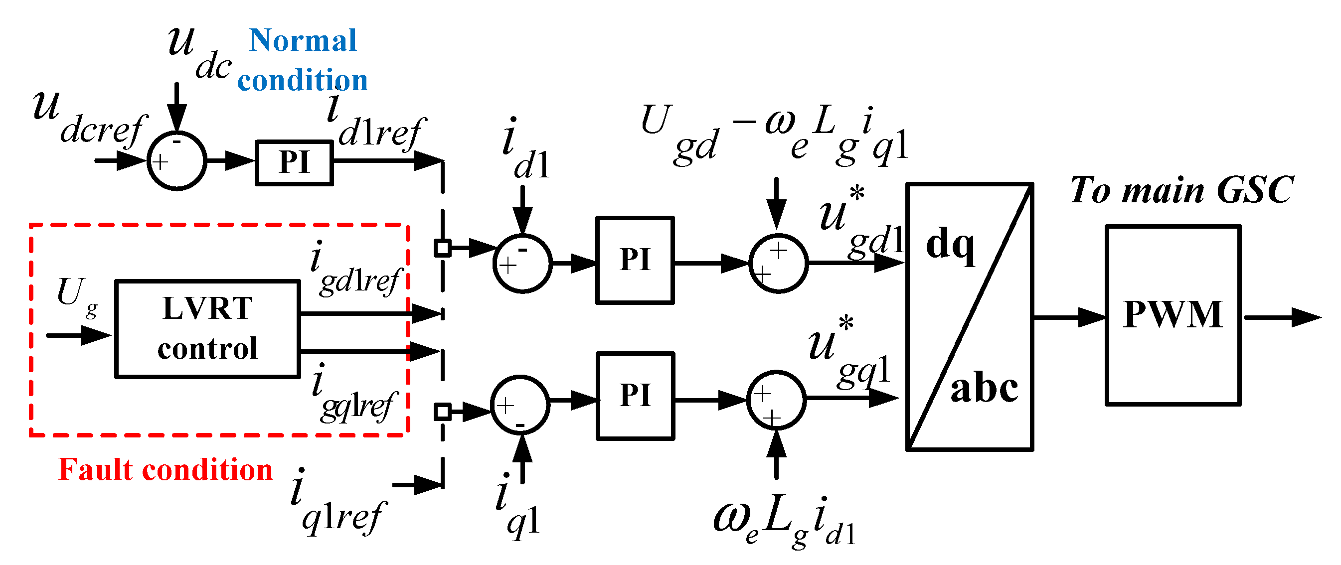
Figure 5 shows the control diagram for the main GSC implemented in synchronous rotating
dq reference frame with its d-axis oriented with the grid voltage vector. The PI regulators with cascade control loops are employed in the GSC control scheme, in which the outer control loops are for DC-link voltage and reactive power regulation, and the inner control loops are for grid side inductor current regulation. To decouple the
q-axis and
d-axis current control in the GSC control loop, the feedforward compensation terms are introduced to control the
d-axis component for the active current regulation and the
q-axis component for the reactive current regulation.
Figure 5.
A control diagram for the main GSC.
Figure 5.
A control diagram for the main GSC.
Under normal conditions, dual closed-loop control is applied to the
d-axis control, where the outer DC-link voltage loop outputs the reference current for the inner current loop, thereby controlling the DC-link voltage to be constant. This structure ensures that the active power output of the generator may be fed through the converter and into the grid in a timely manner. Single closed-loop control is used for the
q-axis control, where the pre-set value of the reactive power determines the reactive current reference. However, under fault conditions, the active and reactive current references of the main GSC are determined by the LVRT control strategy, indicated by red dashed box in
Figure 5.
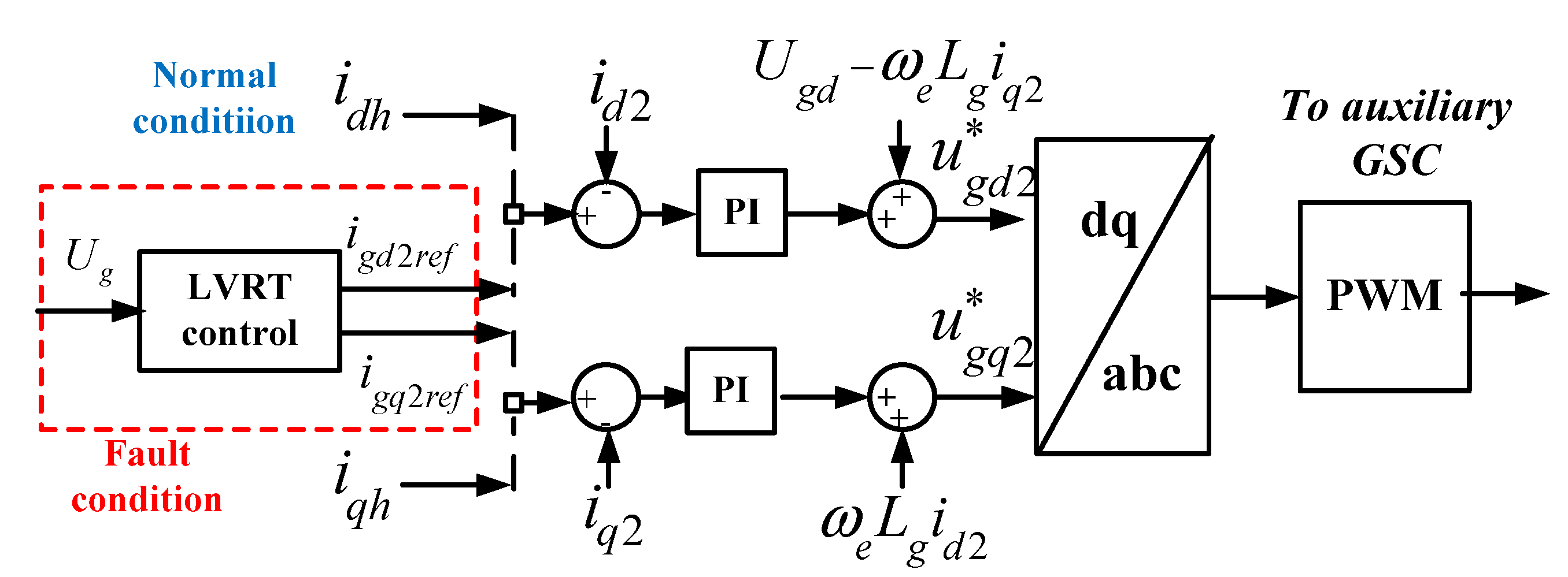
3.3. Auxiliary GSC Control
Similar to the main GSC control, the auxiliary GSC control involves a feedforward compensation to decouple current control. Two control loops are used to control the active and reactive power, respectively, as shown in
Figure 6 (the solid lines).
Figure 6.
A control diagram of the auxiliary GSC.
Figure 6.
A control diagram of the auxiliary GSC.
Under normal conditions, the auxiliary converter operates in APF mode. The reference current of the auxiliary converter is the compensation current for harmonics elimination. Therefore, the harmonic compensation currents idh and iqh are added to the current loop to control the generation of compensation harmonics to improve the power grid power quality.
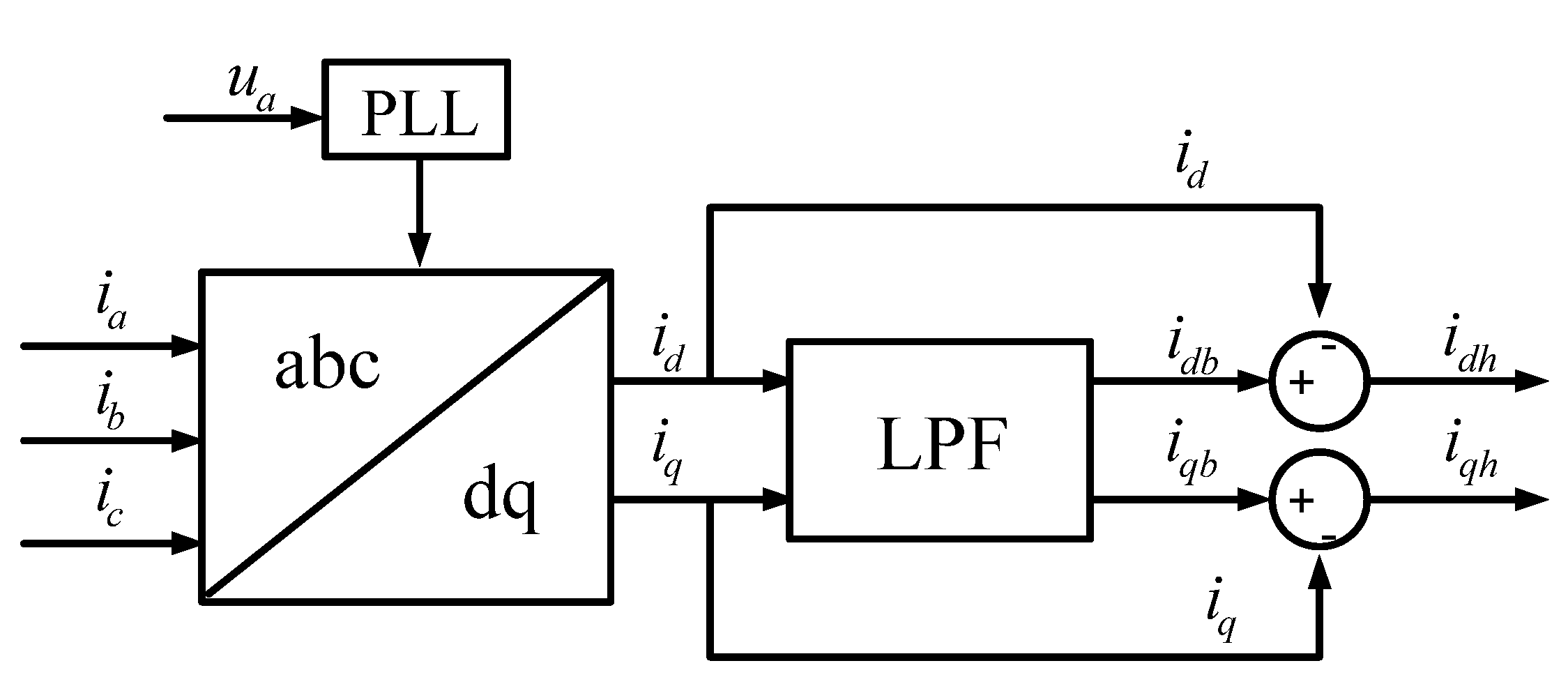
A schematic of harmonic compensation current detection is depicted in
Figure 7. A digital phase-locked loop (PLL) tracks phase “a” of the grid to ensure the accuracy of the current measurement. The three-phase load currents
ia,
ib and
ic are first transformed to the active and reactive current components
id and
iq in the rotating
dq reference frame by an
abc/dq transformation and are subsequently low-pass filtered to obtain the fundamental components
idb and
iqb. The two processes differ because of the harmonic components,
idh and
iqh, in the rotating
dq reference frame,
i.e., the reference current of the auxiliary converter operating in APF mode.
Figure 7.
A schematic of harmonic compensation current detection.
Figure 7.
A schematic of harmonic compensation current detection.
Circulating current may arise from the parallel operation of the main and auxiliary GSCs , resulting in many adverse effects on the system, such as increased power switching devices losses, decreased system efficiency or even damage to the power electronic devices. The potential circulating current between the main and auxiliary GSCs is caused by the character differences of the parallel converters, such as inductor, switching device, switching frequency, dead-time,
etc. But these are the apparent reasons. The intrinsic reason is the discrepancy of zero-axis duty cycles for the parallel converters [
21]. Traditionally, in order to avoid this problem, transformer designed with a certain winding turns-ratio and a certain phase shift is used to break the circulating current route [
22,
23]. The circulating current can also be depressed by proper modulation strategy, for example, a modulation scheme without using zero vectors [
24], or through the zero voltage axis by selecting the appropriate null switching voltage vectors [
25].
In this paper, for simplicity, parallel pulse width modulation with an AC-side isolation transformer [
26,
27], as shown in
Figure 3, is used to eliminate the circulating current that would otherwise arise from the parallel operation of the main and auxiliary grid-side converters.
4. Coordinated LVRT Control Scheme during Grid Faults
The voltage dips caused by grid faults limit the power output of the GSC. If the WT output power is not adjusted, this excess power will cause DC-link overvoltage, endangering the safe operation of the back-to-back converters. Usually, the DC chopper is used to dissipate the surplus power between the generator and the grid to maintain DC-link voltage during grid faults. However, without extra control effort, the power rating of the DC chopper should be full rated considering the worst grid faults scenario. Moreover, it is impossible to mitigate the distortion of the current injected into the grid.
The proposed PMSG WT topology, shown in
Figure 3, presents a system structure that fully exploits the converters capacity to enhance the LVRT capability. The auxiliary GSC can switch to the LVRT mode and can coordinate with the generator-side converter and main GSC to successfully deliver the active power generated by the WTs to the power grid while simultaneously feeding reactive power to the power grid to support grid voltage recovery.
4.1. Hierarchical LVRT Control Principles
The following hierarchy of LVRT control principles, which are based on the depth of a voltage dip, is adopted.
(1) The reactive power support control has a higher priority than the active power balance control.
To avoid the fault further expanding, it is vital to feed reactive power to restore the grid voltage during a grid fault. Moreover, the generated active power is often allowed to reduce by the converter control temporarily during the grid voltage sags. Thus, the WTs should first meet the reactive current requirements in compliance with the grid code to support grid voltage recovery, i.e., the magnitude of a voltage dip should determine the magnitude of the grid-fed reactive current.
(2) The software LVRT strategy has a higher priority than the hardware LVRT strategy.
To minimize the heat dissipation burden on the unloading resistors as much as possible, various types of LVRT control are coordinated to satisfy the fault ride-through requirements and to shorten the time the DC chopper is in operation, especially for a deep grid voltage dip.
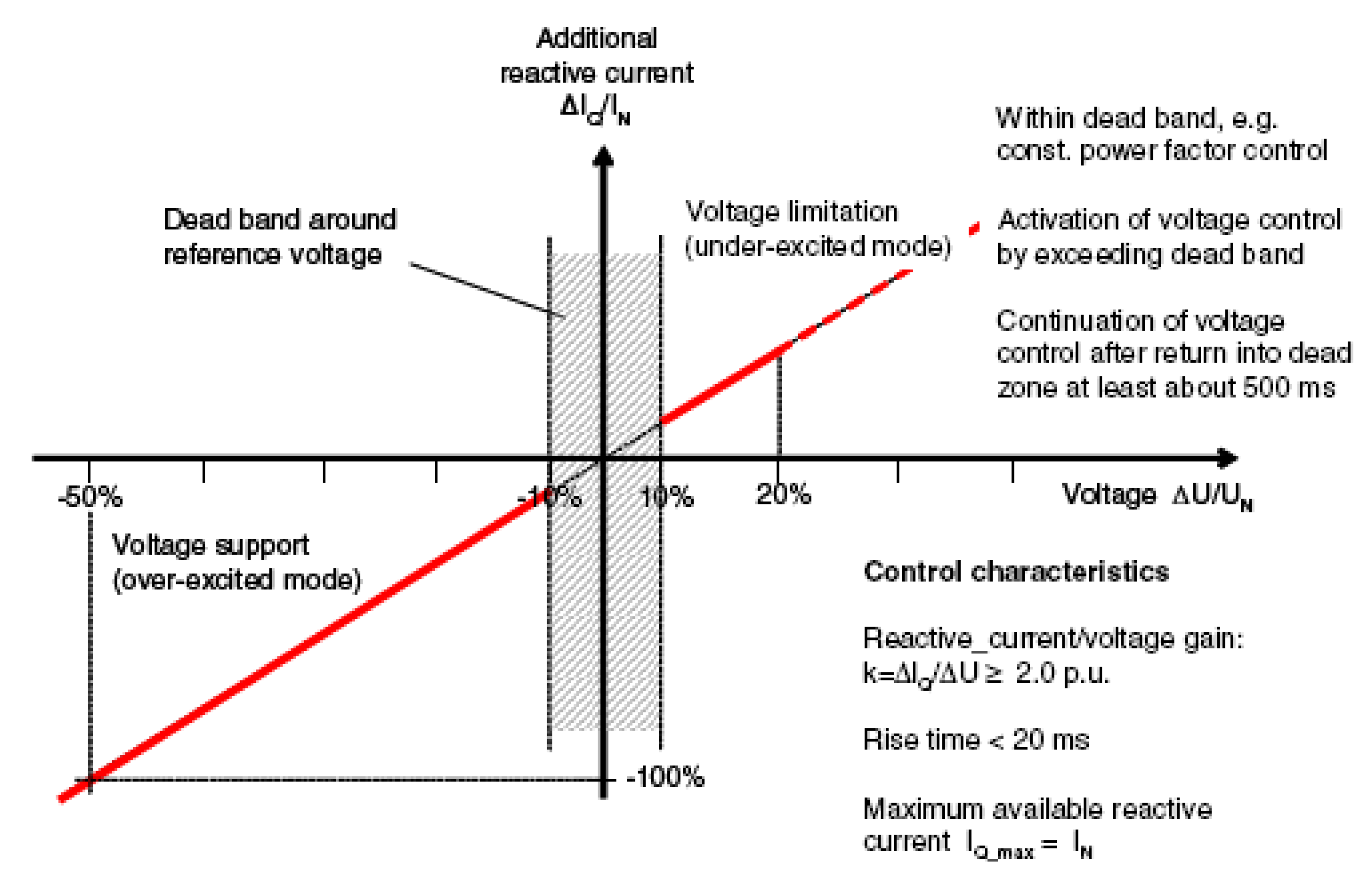
4.2. Reactive Power Support Control
The German grid code from E.ON [
3] is considered in this paper, as shown in
Figure 8, which states that for every decrease of 1% in the rated grid voltage, the wind turbine system should feed a reactive current to the grid that is 2% of the rated current.
Figure 8.
Reactive current support requirement [
3].
Figure 8.
Reactive current support requirement [
3].
Therefore, the reactive current references of the main and auxiliary GSCs for the hierarchical control are:
where
Ug denotes the grid voltage;
Uref denotes the grid voltage before fault and
igq1ref and
igq2ref are the
q-axis reactive current commands of the main and auxiliary GSCs, respectively. All values are given per unit (p.u.) and remain the same in the following sections.
4.3. Active Power Balance Control
After a reactive current support strategy for the system has been determined, the active current references of the main and auxiliary GSCs that maintain the active power balance of the system can be calculated using Equations (6,7):
where
igd1ref and
igd2ref denote the d-axis active current commands of the main and auxiliary GSCs, respectively; and
Ps is the active power output of the system prior to a grid fault.
The grid-side converter current capacity is limited and the priority is given to reactive current to fulfill LVRT requirement during a grid fault, thereby the active current is restricted by:
where
i1max and
i2max are the upper bounds on the main GSC current and the auxiliary GSC current, respectively.
4.4. Hierarchically Coordinated LVRT Control Scheme
The control strategy of initiating two GSCs can only meet the LVRT requirements for certain voltage dips. This voltage range can be calculated by jointly solving Equations (4) to (9). The lower bound on Ug can later be determined at this level. This lower bound corresponds to the first level of the LVRT control hierarchy.
For deeper voltage dips, the current outputs of the two GSCs reach their upper bounds. The generator-side converter control should therefore be initiated to increase the generator speed and to deviate from the maximum power tracking curve. The corresponding decrease in the generator power output allows the energy balance of the system to be maintained. A typical PMSG can operate at approximately 1.4 p.u. of the rated speed. The maximum magnitude of the generator power reduction can be determined from the WT power-speed curve [
28]. The active power reference of the outer power control loop of the generator-side converter can then be calculated from Equation (10):
The lower bound on Ug at this level can be determined using Equations (4,5,7–10). The strategy described above corresponds to the second level of the LVRT control hierarchy.
For a very deep voltage dip, the generator speed reaches its upper limit. Beyond this point, a decreased power output alone cannot satisfy the system energy balance. In this case, the DC chopper circuit should be switched on to maintain the DC-link voltage below 1.1 p.u. This strategy corresponds to the third level of the LVRT control hierarchy.
5. Simulation Results
To verify the feasibility of the proposed configuration and control strategy, simulations were performed using a system model that was constructed using MATLAB/Simulink. The following simulation parameters were used: PMSG rated power, 400 kW; PMSG rated voltage, 690 V; DC-link voltage of Udcref = 1600 V; DC-link capacitance, 10 mF; main GSC capacity, 400 kVA; auxiliary GSC capacity, 200 kVA; upper bound on the converter current, 1.2 to 1.5 p.u. of the rated current value (1.5 p.u. was used in this study); main GSC grid filtering reactance, 2.0 mH; main GSC grid filtering capacitor, 500 uF; auxiliary GSC grid filtering reactance, 1.3 mH; and PWM with a switching frequency of 12.8 kHz is used for both the main and auxiliary GSC. An uncontrolled three-phase diode rectifier was utilized to simulate nonlinear loads with currents of approximately 100 A.
5.1. Operation under Normal Grid Conditions
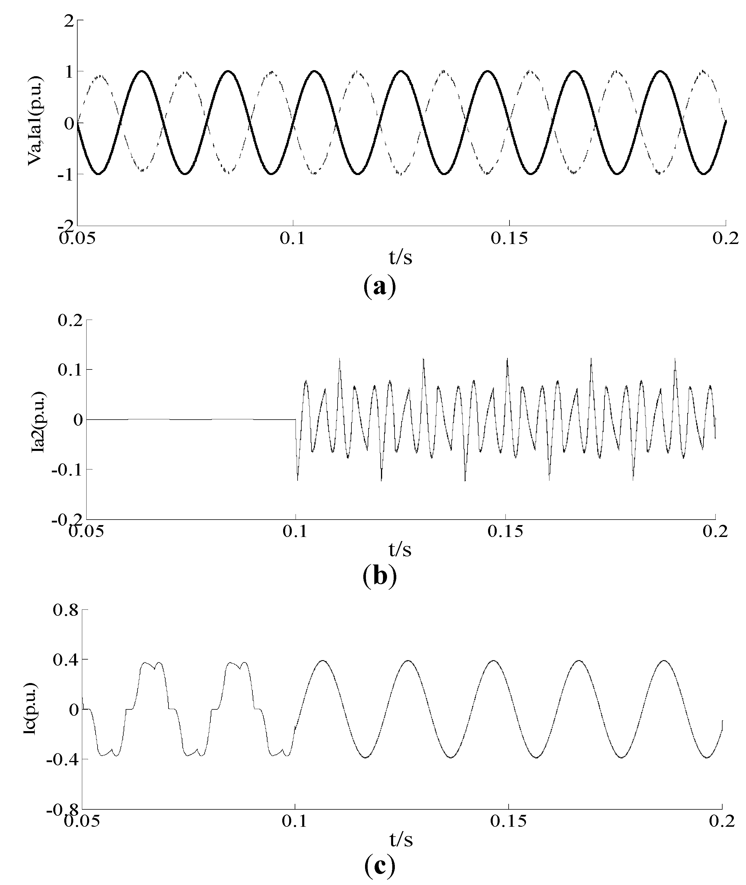
Figure 9 illustrates the system performance under normal conditions with nonlinear loads. At
t = 0.1 s, the auxiliary GSC initiated the APF control mode to implement harmonic compensation for the nonlinear loads around the wind farm.
Figure 9.
The simulation results for the D-PMSG WT with an auxiliary GSC under normal conditions. (a) Phase-a voltage of the power grid (solid line); phase-a current of the main GSC (dashed line); (b) Phase-a current waveform for the auxiliary GSC; (c) The grid current before and after the compensation.
In
Figure 9a, the solid line corresponds to the phase-a grid voltage, and the dashed line corresponds to the phase-a output current of the main GSC,
i.e., the grid-connected current of the main GSC (with a measured current direction that was opposite to the actual flow).
Figure 9a demonstrates that GSC transfers the active power extracted from the wind turbine to the grid at a power factor of 1.
The nonlinear load in the system produced various harmonics in the grid current. At
t = 0.1 s, the auxiliary GSC initiated APF control and the harmonic compensation current is injected to the grid, as shown in
Figure 9b. It can be found from
Figure 9c that the grid current was significantly improved due to this compensation. Therefore, it is evident that the system successfully unified control for the wind power integration and the active power filter under normal operating conditions.
5.2. Operation during Grid Faults
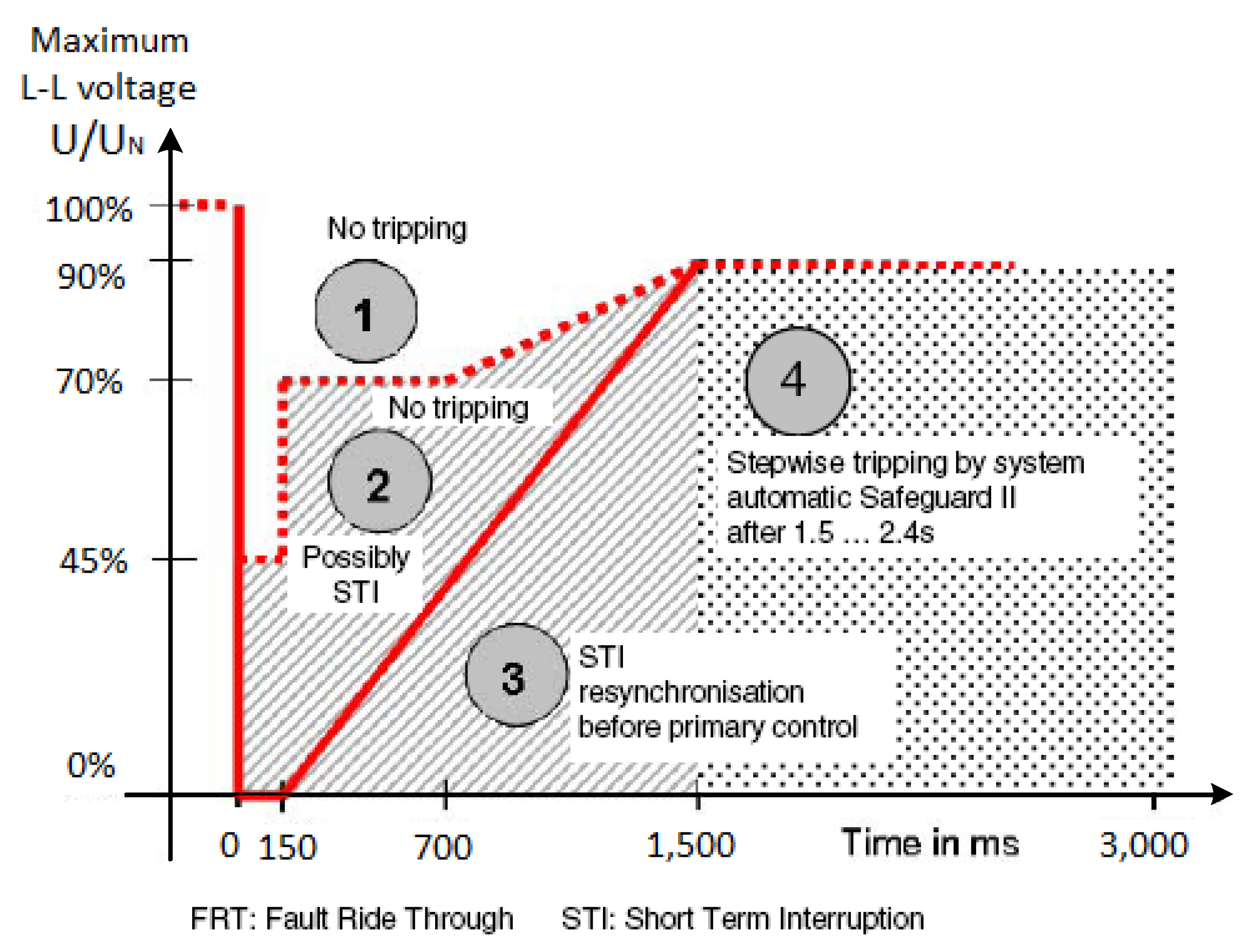
Wind turbines have to withstand not only the most likely unbalanced fault but also three-phase short circuits near the grid connection node. Consequently, zero voltages in all three phases in the connection points have to be considered. According to E.ON, wind farms must withstand voltage drops down to 0% of the nominal voltage for durations up to 150 ms, as shown in
Figure 10.
Figure 10.
Fault ride through requirement [
3].
Figure 10.
Fault ride through requirement [
3].
However, the requirements apply for the connection point to the power grid, generally at HV level. Depending on the network and wind farm configuration, it does not necessarily lead to zero voltages at the wind generator terminal side. Taking into account the typical impedance values for the step-up transformers and interconnecting lines, a relatively simple calculation indicates that the corresponding voltage dip at lower voltage levels, near the WT terminals, are likely to be somewhat above 15% [
29], facilitating compliance to the LVRT requirements.
To validate the effectiveness of the proposed control strategy, the most serious case was considered, in which the WT was operating at the rated wind speed, a power factor of 1 and maximum power output prior to the grid fault, whereas the generator maximum speed reached 1.4 p.u., and the output power was reduced to 0.75 p.u after the grid fault.
Due to the grid faults, at t = 0.2 s, the voltage at WT terminal dropped to 0.8 p.u. for a duration of 0.1 s; at t = 0.3 s, the grid voltage further dropped to 0.5 p.u. for a duration of 0.2 s; and at t = 0.5 s, the grid voltage dropped to 0.15 p.u. for a duration of 0.15 s.
Table 1 shows the calculated
Ug ranges and the corresponding control measures for each level of the LVRT control hierarchy using the parameters of the studied WT power system.
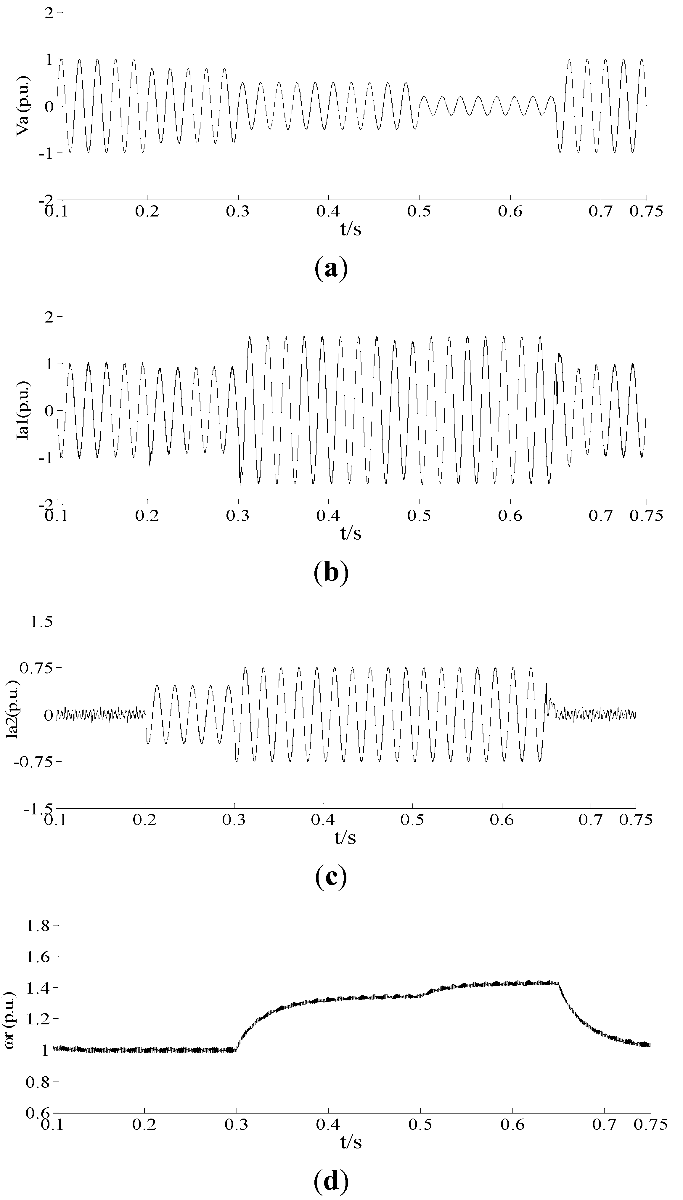
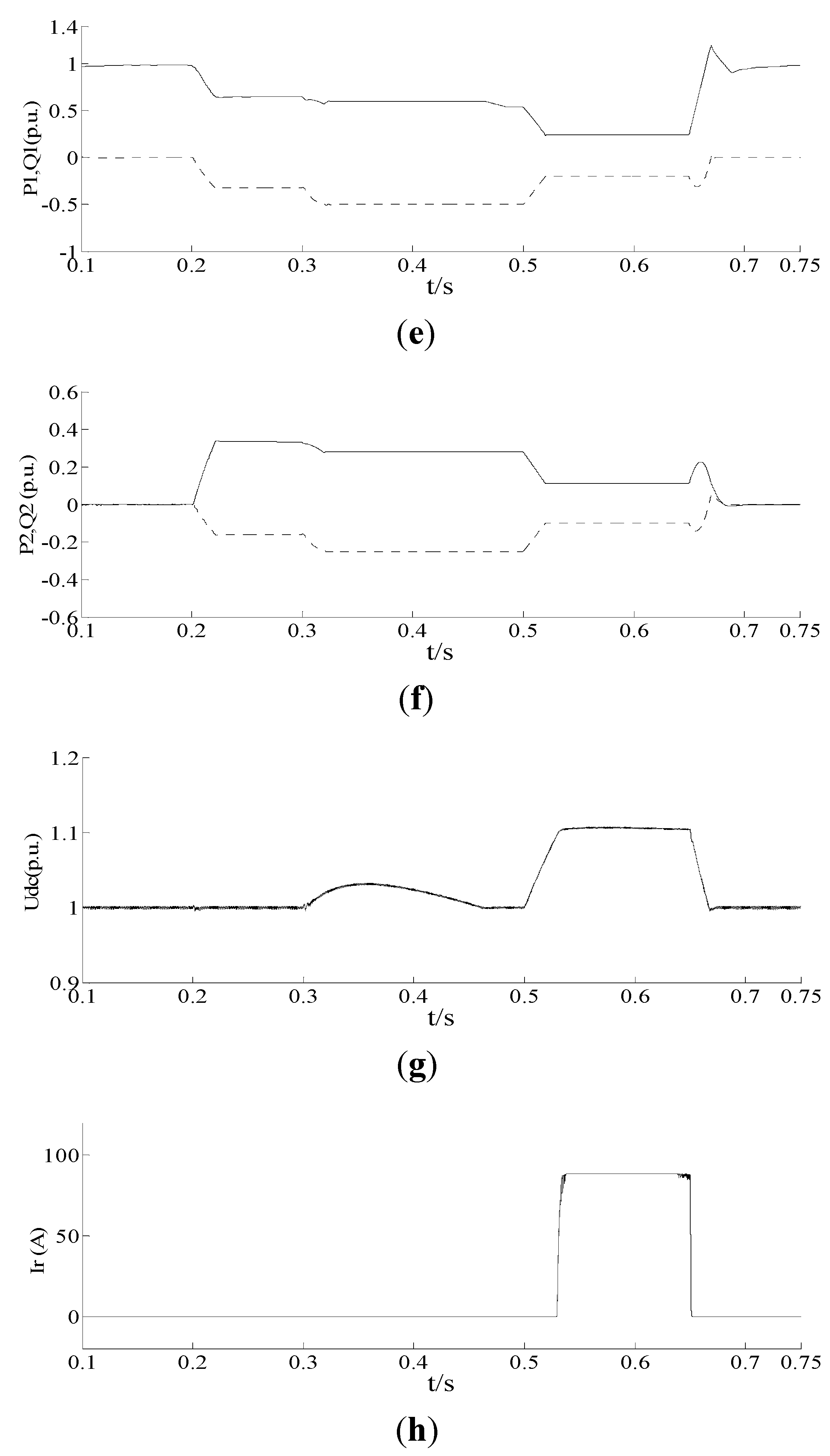
Figure 11 illustrates the system dynamic response during the grid faults.
Table 1.
The Hierarchically coordinated LVRT control scheme.
Table 1.
The Hierarchically coordinated LVRT control scheme.
| Voltage dip level | Grid voltage range | LVRT control strategy |
|---|
| First level | 56% ≤ Ug | initiate only the coordinated control of the two GSCs |
| Second level | 45% ≤ Ug < 56% | add generator-side converter speed control |
| Third level | Ug < 45% | add the use of the DC chopper circuit |
Figure 11.
The simulation results for the D-PMSG WT with an auxiliary GSC during grid faults. (a) Grid phase-a voltage; (b) Main GSC phase-a current; (c) Auxiliary GSC phase-a current; (d) Generator rotation speed; (e) Active power (solid line) and reactive power (dashed line) output of the main GSC; (f) Active power (solid line) and reactive power (dashed line) output of the auxiliary GSC; (g) DC-link voltage; (h) DC chopper current.
Before t = 0.2 s, the wind turbine was operating at the rated speed, the active output of the system was 1 p.u., and the power factor was 1.
At
t = 0.2 s, the grid voltage dropped to 0.8 p.u., and
Ug > 56% (a situation that corresponds to the first level of the control hierarchy). At this time, the auxiliary GSC was no longer operating in APF mode but instead operated with the main GSC to provide the active and reactive outputs. These active and reactive power outputs are shown in
Figure 11e,f, respectively.
At
t = 0.3 s, the grid voltage dropped to 0.5 p.u., and 45% <
Ug < 56% (a situation that corresponds to the second level of the control hierarchy). At this time, the active and reactive outputs of the two GSCs were already fluctuating as necessary. However, the reactive support had reached its upper bound, and the generator speed therefore increased to 1.34 p.u., shown in
Figure 11d, which reduced the output power of the generator to maintain the energy balance of the system. The WT speed responded more slowly, briefly increasing the DC-link voltage, shown in
Figure 11g; however, this voltage remained below 1.05 p.u., in compliance with the LVRT requirements.
At
t = 0.5 s, the grid voltage dropped to 0.15 p.u., and
Ug < 45% (a situation that corresponds to the third level of the control hierarchy). The active and reactive output currents of the GSCs remained unchanged from previous timepoint, and the generator speed had increased to its 1.43 p.u. limit. However, the reduced output power caused by this generator speed increase was insufficient to maintain the energy balance of the system. Thus, the DC chopper was turned on to dissipate the excess energy. The DC chopper current is shown in
Figure 11h. Through this approach, the DC-link voltage was maintained below 1.1 p.u.
After t = 0.65 s, the power grid faults were cleared and the system switched to the unified control mode of grid-connected wind power generation with APF.
Compared with the conventional scheme with DC chopper [
8], as shown in
Figure 11, the grid-side active and reactive current controlled with the proposed strategy can track the profile well defined in E.ON code, and the DC-link voltage can be controlled effectively to keep below the safety limit. In addition, the DC chopper capacity is reduced and the time of the DC chopper in operation is shorten, resulting in minimizing the heat dissipation burden on the unloading resistors.
6. Conclusions
In this paper, a novel topology is developed for a direct-driven PMSG WT system, in which an auxiliary grid-side converter is paralleled with the grid-side converter to enhance low voltage ride-through capability and improve power quality. Under normal conditions, the main GSC ensures that the WT system is smoothly connected to the grid, whereas the auxiliary GSC operates in APF mode to compensate for the harmonic current and to improve the power quality of the grid. During grid faults, a hierarchical LVRT strategy for generator-side converter, main GSC and auxiliary GSC is presented, which provides reactive support to the power grid and maintains the energy balance of the system to achieve an LVRT requirement that complies with grid codes. The LVRT strategy exploits the converters capacity and coordinates the converters control depending on the depth of the voltage dip, thus minimizing the heat dissipation burden on the DC chopper. Compared with the conventional scheme, the proposed system combines wind power integration control, reactive and harmonic current compensation and LVRT operations to improve stability and power quality while remaining cost-effective.


