Article

Coordinated Control of a Doubly-Fed Induction Generator-Based Wind Farm and a Static Synchronous Compensator for Low Voltage Ride-through Grid Code Compliance during Asymmetrical Grid Faults

Tsinghua National Laboratory for Information Science and Technology, Department of Automation, Tsinghua University, Beijing 100084, China
*
Author to whom correspondence should be addressed.
Energies 2013, 6(9), 4660-4681; https://doi.org/10.3390/en6094660
Submission received: 19 July 2013 / Revised: 23 August 2013 / Accepted: 26 August 2013 / Published: 9 September 2013

Abstract

:
This paper aims to explore a viable solution for a doubly-fed induction generator (DFIG)-based wind farm to meet the reactive support requirement of the low voltage ride-through (LVRT) grid code with safe grid-connected operation during asymmetrical grid faults. First, the control scheme for the DFIG-based wind energy conversion system (WECS) is designed. Then, the controllability issue is analyzed by means of an optimal method, and the derived controllable regions indicate that the DFIG-based WECS can only remain controllable under mild asymmetrical fault situations. Afterwards, the static synchronous compensator (STATCOM) is introduced as extra equipment to ensure that the DFIG-based wind farm remains controllable under severe asymmetrical fault situations. For this purpose, a voltage compensation control scheme and a corresponding capacity matching method for the STATCOM are proposed. The simulation results verify that, with the proposed coordinated control between the DFIG-based wind farm and the STATCOM, the required positive-sequence reactive current can be supplied to support the power grid. The oscillations on the electromagnetic torque and direct current (DC)-link voltage of the DFIG-based WECS can also be eliminated. Therefore, the control scheme can be helpful to improve the reliability of both the wind farm and the power system during grid faults.

1. Introduction

With the increasing penetration of wind power energy in the power system, the capability of low voltage ride-through (LVRT) is becoming a requirement for grid-connected wind farms in the grid codes of more countries to ensure the reliable operation of the power system during grid faults [1,2,3]. More specifically, the wind generation systems need to remain connected to the power grid during grid faults, while providing effective voltage support as the conventional generation systems. Among the different types of wind energy conversion systems (WECSs), a wind turbine with doubly-fed induction generator (DFIG) is used most commonly in commercial MW-class wind generation systems, since the needed capacity of its converter is only 25%–30% of the system rated power [4]. However, DFIG-based WECS is very sensitive to grid disturbances; a sudden grid voltage dip may even destroy its converters [5,6,7]. Generally, the whole LVRT process for DFIG-based WECS can be divided into three continuous periods according to the LVRT grid codes [8], the initial period after the grid fault occurs (the first period), the low voltage-sustaining period (the second period) and the grid voltage recovery period after fault clearance (the third period). To achieve complete LVRT, the control objectives for DFIG-based WECS in each period are different.
In the initial period after a grid fault occurs, a large electromotive force (EMF) is induced in the rotor circuit of the DFIG by the transient decay component of the stator flux, which results from the stator voltage dip [5,6,7]. To ensure the safe operation of the rotor-side converter (RSC), the control objective for DFIG-based WECS in this period is to restrain the rotor surge current caused by the large EMF [8]. The corresponding control schemes have been investigated thoroughly in references [5,9,10,11,12,13,14]. The rotor crowbar protection is a simple but effective measure, which is commonly used at present [15,16]. When a grid fault occurs, the active crowbar is triggered to short the rotor circuit of the DFIG, which can accelerate the decay of the transient stator flux while protecting the RSC [17,18]. The previous studies for the first period of the DFIG’s LVRT are comprehensive; therefore, this paper will focus on the second period.
When the transient stator flux is almost damped out, it enters the low voltage-sustaining period. The crowbar is cut off, and the RSC recovers the control of the DFIG. The control objective for DFIG-based WECS in this period is to support the grid voltage by injecting reactive current into the network [8]. For symmetrical grid faults, the conventional vector control scheme can be applied here with the reactive current reference set to follow the LVRT grid codes [19]. However, the control issue becomes more complicated during asymmetrical grid faults.
Under asymmetrical grid fault conditions, the imbalance in the grid voltage has negative impacts on the operation of the DFIG and the grid stability. Specifically, the existence of negative-sequence voltage brings double grid frequency oscillations on the active and reactive powers, as well as on the electromagnetic torque [20,21]. To eliminate such oscillations, several control schemes with sequence decomposition and advanced algorithms have been proposed to address small voltage imbalance conditions [22,23,24,25,26,27,28]. In addition, the impact of the limited converter rating on the control of DFIG-based WECS is analyzed in references [8,29]. Furthermore, the detailed power generation capability and feasibility regions of the DFIG with limited RSC rating considered are derived in reference [30]. Consequently, for severe asymmetrical fault situations, the control targets proposed in references [22,23,24,25,26,27,28] can hardly be achieved due to the converter capacity limitation.
The previous studies on the second period of the asymmetrical LVRT mainly focus on keeping the DFIG-based WECS connected to the power grid with safe operation. However, the reactive support requirement of the LVRT grid code during asymmetrical grid faults is already under discussion in some countries. For example, as indicated in the German ordinance “SDLWindV”, at least a 2% rated positive-sequence reactive current per percent positive-sequence voltage drop should be supplied by the WECS when the positive-sequence voltage drop is more than 10% [3]. Therefore, the grid voltage support requirement should be considered in the control scheme design of DFIG-based WECS.
As mentioned above, the effects of the control schemes in the second LVRT period are limited by the converter capacity of the DFIG-based WECS when the grid fault is severe. To improve the LVRT capability of a wind farm containing amounts of DFIG-based WECSs, the wind farm can be equipped with some extra equipment to alleviate the voltage dip situations. Since the static synchronous compensator (STATCOM) supports the voltage at the point of common coupling (PCC) by injecting reactive current into the network, it is more suitable for a Chinese wind farm integrated into a weak power grid with long transmission lines [31]. The control strategy of STATCOM during LVRT is reported in references [32,33,34]; however, these studies focus on verifying the effectiveness of STATCOM under symmetrical grid fault conditions. For asymmetrical grid faults, some critical problems lack theoretical analyses, such as the necessity for a STATCOM, the control strategy and the capacity matching method for the STATCOM, if it is needed.
Consequently, for the second period of an asymmetrical LVRT, there is a need for a viable solution for the DFIG-based wind farm to meet the reactive support requirement of the LVRT grid code with safe grid-connected operation.
Within that framework, this paper has been organized as follows. In Section 2, after reviewing the DFIG and grid-side converter (GSC) modeling under unbalanced grid voltage conditions, the control schemes for RSC and GSC in the second period of an asymmetrical LVRT are designed, taking the LVRT grid code into consideration. Then, the controllability analysis of the whole DFIG-based WECS is formulated as an optimization problem in Section 3. After solving the optimization problem, the controllable regions represented by the unbalanced degree of grid voltage are given. These results indicate that a DFIG-based WECS can only achieve its control objectives under mild asymmetrical fault situations. In Section 4, the STATCOM is introduced to ensure that the DFIG-based WECSs in the wind farm remain controllable under severe asymmetrical fault situations. To reduce the unbalanced degree of fault voltage while mitigating the oscillations on the direct current (DC)-link voltage of the STATCOM, a voltage compensation control scheme and corresponding capacity matching method for the STATCOM are proposed. Section 5 gives the simulation verifications. Finally, the conclusions are summarized in Section 6.

2. Control Scheme for DFIG-Based WECS

Under unbalanced conditions, the positive- and negative-sequence currents of both RSC and GSC should be controlled independently, so as to meet the reactive support requirement of the LVRT grid code, while maintaining safe operation of the DFIG-based WECS. Based on the dynamic modeling developed in references [22,24,27,28], control schemes for RSC and GSC will be designed respectively in this section.

2.1. Control Scheme for RSC

When stator and rotor loop circuits both use the motor convention, the voltage and flux linkage equations of DFIG in the stator-oriented reference frame, α β , can be expressed in space-vector form as [22,27,28]:
v s α β = R s i s α β + d ψ s α β / d t v r α β = R r i r α β + d ψ r α β / d t - j ω r ψ r α β
ψ s α β = L s i s α β + L m i r α β ψ r α β = L m i s α β + L r i r α β
where R s and R r are the stator and rotor resistances; L s , L r and L m are the stator inductance, rotor inductance and mutual inductance; v s α β , v r α β , i s α β , i r α β , ψ s α β and ψ r α β are the space vectors of voltage, current and flux linkage; ω r is the rotor electrical angular speed; and superscript “ ” indicates the quantity referring to the stator side.
As the electromagnetic quantity under unbalanced conditions contains both positive- and negative-sequence components, the above space vectors of voltage, current and flux linkage can be decomposed as:
F α β = F α β p + F α β n = F d q + p e j ω s t + F d q - n e - j ω s t
where F indicates the space vectors of voltage, current or flux linkage; superscripts “p and n” indicate the positive- and negative-sequence components; subscripts “ d q + and d q - ” indicate the reference frames rotating at the angular speeds of ω s and - ω s ; and ω s is the synchronous electrical angular speed.
In the positive- and negative-sequence stator voltage orientation, the d + axis is fixed to v s α β p and the d - axis is fixed to v s α β n , respectively; then v s q + p = v s q - n = 0 . The instantaneous active and reactive powers of DFIG stator can be expressed as [22,27,28]:
P s + j Q s = - 3 2 L s v s α β ( ψ ^ s α β - L m i ^ r α β ) = [ P s 0 + P s s i n 2 sin ( 2 ω s t ) + P s c o s 2 cos ( 2 ω s t ) ] + j [ Q s 0 + Q s s i n 2 sin ( 2 ω s t ) + Q s c o s 2 cos ( 2 ω s t ) ]
where:
P s 0 Q s 0 P s s i n 2 P s c o s 2 Q s s i n 2 Q s c o s 2 = - 3 2 ω s L s 0 ( v s d + p ) 2 - ( v s d - n ) 2 2 v s d + p v s d - n 0 0 0 + 3 L m 2 L s v s d + p 0 v s d - n 0 0 - v s d + p 0 - v s d - n 0 - v s d - n 0 v s d + p v s d - n 0 v s d + p 0 - v s d - n 0 v s d + p 0 0 - v s d - n 0 - v s d + p i r d + p i r q + p i r d - n i r q - n
Similarly, the DFIG electromagnetic torque can be expressed as [22,27,28]:
T e = - 3 L m 2 L s n p I m [ ψ s α β i ^ r α β ] = T e 0 + T e s i n 2 sin ( 2 ω s t ) + T e c o s 2 cos ( 2 ω s t )
where n p is the DFIG pole pairs:
T e 0 T e s i n 2 T e c o s 2 = - 3 L m n p 2 L s ω s - v s d + p 0 v s d - n 0 0 - v s d - n 0 - v s d + p v s d - n 0 - v s d + p 0 i r d + p i r q + p i r d - n i r q - n
It is clear from Equations (4)–(7) that the unbalanced grid voltage can bring double grid frequency oscillations on the power and electromagnetic torque of a DFIG. As the torque oscillations may damage the drive train and result in tripping of the wind turbine [20,21], the RSC needs to be in charge of eliminating it.
According to Equation (7), to force T e s i n 2 = T e c o s 2 = 0 , the positive- and negative-sequence rotor current references should satisfy the following relations:
i r d - n * = ( v s d - n / v s d + p ) i r d + p * i r q - n * = - ( v s d - n / v s d + p ) i r q + p *
in which v s d + p , v s d - n can be regarded as the known parameters, since they can be detected online with phase-locked-loop (PLL) techniques [35,36].
Taking the German ordinance “SDLWindV” as an example, to meet the positive-sequence reactive current injection requirement, the positive-sequence stator and rotor reactive current references should be set as:
i s q + p * = 2 ( 1 - v s d + p / V s p r e ) I s r a t e , ( 0 . 5 V s p r e v s d + p < 0 . 9 V s p r e ) I s r a t e , ( 0 < v s d + p < 0 . 5 V s p r e )
i r q + p * = - v s d + p / ( ω s L m ) - ( L s / L m ) i s q + p *
where I s r a t e is the rated stator current; and V s p r e is the stator voltage magnitude before gird faults.
Apart from the rotor reactive current, the remaining rotor current margin will be assigned between the positive- and negative-sequence rotor active currents according to Equation (8), as in Equation (11):
i r d + p * = ( v s d + p v s d + p + v s d - n I r max ) 2 - ( i r q + p * ) 2 i r d - n * = ( v s d - n v s d + p + v s d - n I r max ) 2 - ( i r q - n * ) 2
where I r max is the maximum rotor current, and it is supposed to be 1.5 pu.
Once the positive- and negative-sequence current references of RSC are calculated from Equations (8)–(11), they must be controlled precisely to achieve the RSC’s control targets. The control diagram of the RSC is shown in Figure 1. In the diagram, Δ v r d q + p and Δ v r d q - n are the feed-forward terms that intend to decouple the control of i r d q + p and i r d q - n [8]. The control priority of RSC discussed in [37] is implemented by designing the current limiter in Figure 1b. Specifically, eliminating the oscillations on DFIG electromagnetic torque has a higher priority than meeting the reactive support requirement. The PLL block in Figure 1a is performed by a dual second-order generalized integrator (SOGI)-based PLL (DSOGI-PLL) [35].
Figure 1. Control diagram of the rotor-side converter (RSC) during asymmetrical grid faults.
Energies 06 04660 g001

2.2. Control Scheme for GSC

The voltage equation of GSC in the stationary reference frame, α β , can be expressed as [24]:
v s α β = R g i g α β + L g d i g α β / d t + u g α β
where v s α β , u g α β and i g α β are the space vectors of the grid voltage, GSC input terminal voltage and alternating current (AC) input current, respectively; R g and L g are the GSC input resistance and inductance.
In the positive- and negative-sequence grid voltage orientation, the instantaneous active and reactive powers from GSC to the grid can be expressed as [24]:
P g + j Q g = - 3 2 v s α β i ^ g α β = [ P g 0 + P g s i n 2 sin ( 2 ω s t ) + P g c o s 2 cos ( 2 ω s t ) ] + j [ Q g 0 + Q g s i n 2 sin ( 2 ω s t ) + Q g c o s 2 cos ( 2 ω s t ) ]
where:
P g 0 Q g 0 P g s i n 2 P g c o s 2 Q g s i n 2 Q g c o s 2 = - 3 2 v s d + p 0 v s d - n 0 0 - v s d + p 0 - v s d - n 0 - v s d - n 0 v s d + p v s d - n 0 v s d + p 0 - v s d - n 0 v s d + p 0 0 - v s d - n 0 - v s d + p i g d + p i g q + p i g d - n i g q - n
The DC-link voltage equation is:
C d V d c d t = P r V d c - P g V d c = ( P e - P s ) - P g V d c
where P e is the electromagnetic power of DFIG, P e = T e ω r / n p .
According to Equations (4), (6) and (13), there are:
C V d c d V d c d t = [ ( P e 0 - P s 0 ) - P g 0 ] + [ ( P e s i n 2 - P s s i n 2 ) - P g s i n 2 ] sin ( 2 ω s t ) + [ ( P e c o s 2 - P s c o s 2 ) - P g c o s 2 ] cos ( 2 ω s t )
V d c = V d c 0 + V d c s i n 2 sin ( 2 ω s t ) + V d c c o s 2 cos ( 2 ω s t )
where:
V d c s i n 2 = 1 2 ω s C V d c 0 [ ( P e c o s 2 - P s c o s 2 ) - P g c o s 2 ] V d c c o s 2 = - 1 2 ω s C V d c 0 [ ( P e s i n 2 - P s s i n 2 ) - P g s i n 2 ]
It is clear from Equations (13)–(18) that the unbalanced grid voltage can bring double grid frequency oscillations on the GSC power and DC-link voltage. As the DC-link voltage fluctuations may cause harmonics in the converter output, as well as the over or under-voltage protection, resulting in tripping of the converters [20,21], the GSC needs to be in charge of eliminating it.
According to Equation (18), to force V d c s i n 2 = V d c c o s 2 = 0 , the GSC powers should satisfy the following relations:
P g s i n 2 = P r s i n 2 = P e s i n 2 - P s s i n 2 P g c o s 2 = P r c o s 2 = P e c o s 2 - P s c o s 2
Similar to the RSC, the positive-sequence GSC reactive current reference should be set as:
i g q + p * = 2 ( 1 - v s d + p / V s p r e ) I g r a t e , ( 0 . 5 V s p r e v s d + p < 0 . 9 V s p r e ) I g r a t e , ( 0 < v s d + p < 0 . 5 V s p r e )
where I g r a t e is the rated GSC current.
According to Equation (14), and making use of Equations (19) and (20), the other components of GSC current references can be derived as shown below:
i g d + p * i g d - n * i g q - n * = - 2 3 v s d + p v s d - n 0 0 0 v s d + p v s d - n v s d + p 0 - 1 P g 0 ( P e s i n 2 - P s s i n 2 ) - 3 2 v s d - n i g q + p * P e c o s 2 - P s c o s 2
where P g 0 is given by the output of the DC-link voltage regulator.
The control diagram of the GSC is shown in Figure 2. The control priority of GSC discussed in reference [37] is implemented by designing the current limiter in Figure 2b. Specifically, eliminating the oscillations on the DC-link voltage has a higher priority than meeting the reactive support requirement.
Figure 2. Control diagram of the grid-side converter (GSC) during asymmetrical grid faults.
Energies 06 04660 g002

3. Controllable Regions of DFIG-Based WECS

In Section 2, the control scheme for DFIG-based WECS has been designed to meet the reactive support requirement of LVRT grid code, while maintaining safe operation of the system. Obviously, the above two control targets cannot be always achieved, due to the converter capacity limitation. In this section, the controllability of DFIG-based WECS will be analyzed by the optimal method to explore its controllable regions.

3.1. Controllable Regions with Limited RSC Rating Considered

Considering that R s and R r in Equation (1) are small enough, so that their impacts can be neglected, from Equations (1) and (2), the rotor voltage equation of DFIG can be expressed as:
v r α β = - j ω r σ L r i r α β + σ L r d i r α β d t + L m L s ( v s α β - j ω r ψ s α β )
Under the steady-state, Equation (22) can be represented by its positive- and negative-sequence components, as in Equation (23):
v r d q + p = L m L s s v s d q + p + j s ω s σ L r i r d q + p v r d q - n = L m L s ( 2 - s ) v s d q - n - j ( 2 - s ) ω s σ L r i r d q - n
where σ = 1 - L m 2 / ( L s L r ) is the leakage factor; and s = 1 - ω r / ω s is the slip of DFIG.
According to Equation (23), the steady-state positive- and negative-sequence equivalent rotor circuits of DFIG can be found as shown in Figure 3 [37]. L m s v s d q + p / L s and L m ( 2 - s ) v s d q - n / L s are the positive- and negative-sequence EMFs in the rotor circuit; j s ω s σ L r and - j ( 2 - s ) ω s σ L r are the positive- and negative-sequence equivalent rotor inductances.
Figure 3. Steady-state equivalent rotor circuit of doubly-fed induction generator (DFIG).
Energies 06 04660 g003
As shown in Figure 3, the equivalent rotor inductances present differently in the positive- and negative-sequence circuits. As the slip range of DFIG is generally between - 0 . 3 + 0 . 3 , take s = - 0 . 1 for example, the negative-sequence equivalent rotor inductance will be 21-times of the positive-sequence one. As a result, to generate i r d q + p and i r d q - n with the same magnitude, the negative-sequence voltage the RSC needs to supply will be much larger than the positive-sequence one. It is clear that the control capability of RSC for the negative-sequence rotor current is much less than that for the positive-sequence rotor current due to the DC-link voltage limitation.
Furthermore, it can be seen from Equation (8) that the negative-sequence rotor current references are in proportion to the unbalanced degree of the grid voltage ( δ = v s d - n / v s d + p ). Consequently, the more severe the grid fault is (i.e., the larger δ is), the larger the negative-sequence rotor current references are, and then the less controllable the DFIG becomes. As a result, the derivation of DFIG’s controllable regions can be formulated as a constrained optimization problem, as in Equation (24):
max δ = v s d - n / v s d + p | v r d q + p * | + | v r d q - n * | V d c 3 | i r d q + p * | + | i r d q - n * | I r max ( 1 - 1 n ) V s p r e v s d + p < V s p r e , 0 < v s d - n 1 n V s p r e
where n represents the type of asymmetrical grid fault, for single-phase faults ( ϕ - g ), n = 3 ; for phase-to-phase faults ( 2 ϕ ), n = 2 [7,38,39].
Substituting Equations (8)–(11) and (23) into Equation (24), the constrained optimization problem can be solved with an iterative solution by computer.

3.2. Controllable Regions with Limited RSC and GSC Rating Considered

To obtain the controllable regions of the whole DFIG-based WECS but not only the DFIG, the impact of limited GSC rating should be also considered along with the RSC. Since the GSC is directly connected to the grid via transformers, unlike the RSC, there is no limited voltage issue [29]. Therefore, the focus can be placed on the impact of GSC’s current limitation on the realization of its control targets proposed in Section 2.2.
According to Equation (16), there is P g 0 = P e 0 - P s 0 under the steady-state; thus i g d q + p * and i g d q - n * can be represented as functions of v s d q + p and v s d q - n by solving Equation (21). As a result, Equation (24) can be further improved as:
max δ = v s d - n / v s d + p | v r d q + p * | + | v r d q - n * | V d c 3 | i r d q + p * | + | i r d q - n * | I r max | i g d q + p * | + | i g d q - n * | I g max ( 1 - 1 n ) V s p r e v s d + p < V s p r e , 0 < v s d - n 1 n V s p r e
where I g max is the maximum GSC current, and it is supposed to be 1.5 pu.
With the DFIG-based WECS parameters given in Table 1 and Table 2, Figure 4 shows the computation results of the constrained optimization problems as in Equations (24) and (25). The controllable regions associated with each case is the area below its corresponding line in Figure 4, and the tolerated δ max is given in Table 3.
Table 1. Electric parameters of a 1.5 MW DFIG.
ParameterValueParameterValue
Rated stator voltage690 VMutual inductance L m 2.9 pu
Pairs of poles n p 2Stator leakage inductance L l s 0.18 pu
Turn ratio1:3Rotor leakage inductance L l r 0.16 pu
Stator resistance R s 0.023 puRated stator current I s r a t e 1105 A
Rotor resistance R r 0.016 puRated rotor current I r r a t e 1359 A
Table 2. Grid-side converter parameters.
ParameterValueParameterValue
Reactor inductance L g 1 mHRated current I g r a t e 453 A
DC-link capacitor C38,000 μFCommon DC-link voltage reference1,200 V
Figure 4. Controllable regions of a DFIG-based wind energy conversion system (WECS) through its operative slip range.
Energies 06 04660 g004
Table 3. Tolerated δ max with different slips.
Slip s−0.3−0.2−0.100.10.20.3
δ max [Equation (24), n = 3 ]0.04420.09380.14800.20750.16420.11570.0607
δ max [Equation (25), n = 3 ]0.03510.08330.13370.18540.14850.10280.0485
Though the controllable regions of DFIG-based WECS with limited RSC rating considered have been explored by means of various approaches and represented in different forms [30,37], it is worth pointing out that, with regard to the proposed control scheme for DFIG-based WECS in Section 2, the limited GSC rating is the primary factor, as shown in Figure 4.
Consequently, due to the converter capacity constraint, the control targets of DFIG-based WECS can only be achieved under mild asymmetrical fault situations (i.e., small δ). Therefore, to ensure the DFIG-based WECS stay controllable even under severe asymmetrical fault situations (i.e., large δ), STATCOM with the function of reducing the unbalanced degree of fault voltage is necessary for a wind farm containing amounts of DFIG-based WECSs.

4. Control Scheme and Capacity Matching of STATCOM

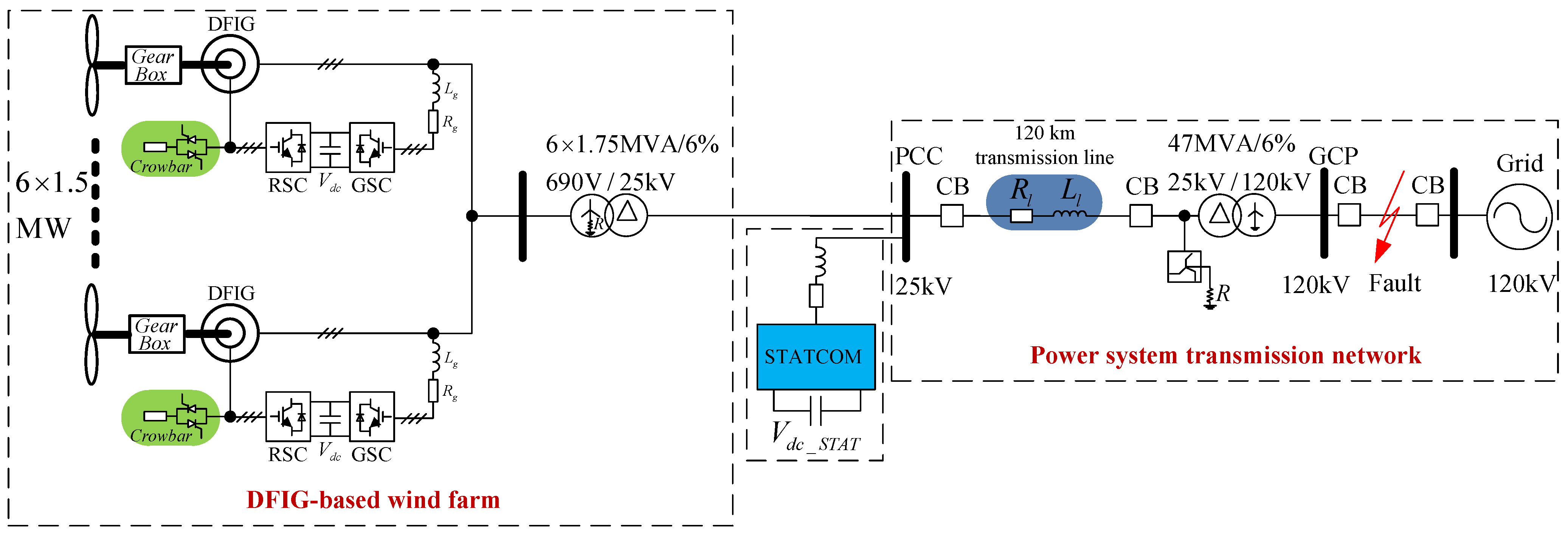
The typical diagram of the power system integrated with a wind farm [8,37] is shown in Figure 5. Wind power is first exported to the medium voltage distribution network at the PCC through a Y/Delta-configured step-up transformer, where the STATCOM is located to dynamically adjust the PCC voltage. Afterwards, via a long transmission line, wind power is integrated into the power grid at the grid connection point (GCP) through another Delta/Y-configured step-up transformer, at the medium voltage side of which a grounding transformer is employed for short-circuit protection.
Figure 5. A grid-connected DFIG-based wind farm equipped with a static synchronous compensator (STATCOM).
Energies 06 04660 g005
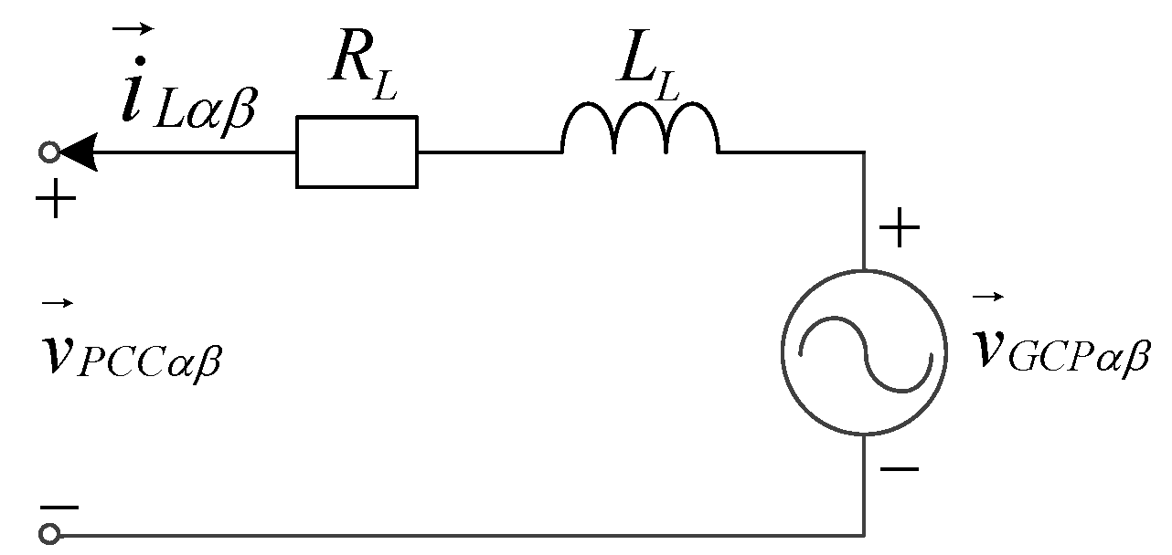
The equivalent circuit of the power system transmission network in Figure 5 can be given as Figure 6 [40], and the voltage equation in the stationary reference frame, α β , can be expressed as:
v P C C α β = - R L i L α β - L L d i L α β / d t + v G C P α β
where v G C P α β , v P C C α β and i L α β are the space vectors of GCP voltage, PCC voltage and transmission current, respectively; R L and L L are the equivalent resistance and inductance of the transmission network.
Figure 6. Equivalent circuit of the power system transmission network.
Energies 06 04660 g006
Since the resistive voltage drop can be neglected on the long transmission line [40] under the steady-state in the positive- and negative-sequence v P C C orientation, Equation (26) can be simplified to:
v P C C d + p = ω s L L i L q + p + v G C P d + p v P C C d - n = - ω s L L i L q - n + v G C P d - n
It is clear from Equation (27) that the positive- and negative-sequence components of PCC voltage can be controlled by correctly injecting positive- and negative-sequence reactive currents, respectively. Therefore, under severe asymmetrical fault situations, STATCOM can reduce the unbalanced degree of PCC voltage into the controllable regions of DFIG-based WECS by means of reactive current injection.
Similar to the GSC, the instantaneous active and reactive powers from STATCOM to the grid can be expressed as:
P S T A T + j Q S T A T = - 3 2 v P C C α β i ^ S T A T α β = [ P S T A T 0 + P S T A T s i n 2 sin ( 2 ω s t ) + P S T A T c o s 2 cos ( 2 ω s t ) ] + j [ Q S T A T 0 + Q S T A T s i n 2 sin ( 2 ω s t ) + Q S T A T c o s 2 cos ( 2 ω s t ) ]
where:
P S T A T 0 Q S T A T 0 P S T A T s i n 2 P S T A T c o s 2 Q S T A T s i n 2 Q S T A T c o s 2 = - 3 2 v P C C d + p 0 v P C C d - n 0 0 - v P C C d + p 0 - v P C C d - n 0 - v P C C d - n 0 v P C C d + p v P C C d - n 0 v P C C d + p 0 - v P C C d - n 0 v P C C d + p 0 0 - v P C C d - n 0 - v P C C d + p i S T A T d + p i S T A T q + p i S T A T d - n i S T A T q - n
The DC-link voltage of STATCOM is:
V d c _ S T A T = V d c _ S T A T 0 + V d c _ S T A T s i n 2 sin ( 2 ω s t ) + V d c _ S T A T c o s 2 cos ( 2 ω s t )
where:
V d c _ S T A T s i n 2 = - 1 2 ω s C V d c _ S T A T 0 P S T A T c o s 2 V d c _ S T A T c o s 2 = 1 2 ω s C V d c _ S T A T 0 P S T A T s i n 2
It can be seen from Equations (28)–(31) that the unbalanced PCC voltage can also bring double grid frequency oscillations on the DC-link voltage of STATCOM. As a result, the positive- and negative-sequence STATCOM current references should be set as follows to mitigate its DC-link voltage fluctuations:
i S T A T d + p * i S T A T d - n * = - 2 3 v P C C d + p v P C C d - n v P C C d - n v P C C d + p - 1 P S T A T 0 0
i S T A T q + p * = k v P C C d + p v P C C d - n i S T A T q - n * , ( 0 k 1 )
where P S T A T 0 is given by the output of the DC-link voltage regulator; i S T A T q - n * is given by the output of the negative-sequence PCC voltage regulator; and k determines the oscillation magnitude on the DC-link voltage of STATCOM, i.e., the larger k is, the smaller the oscillation is.
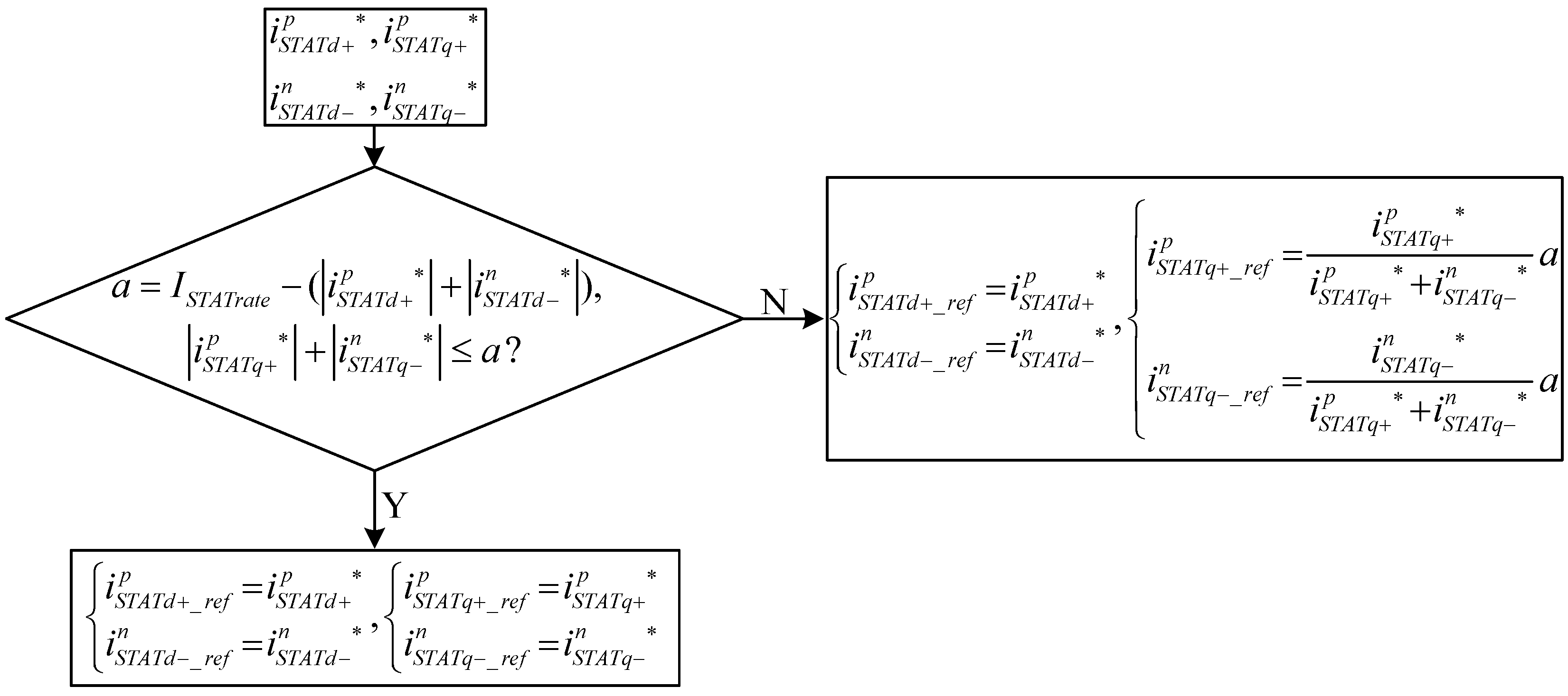
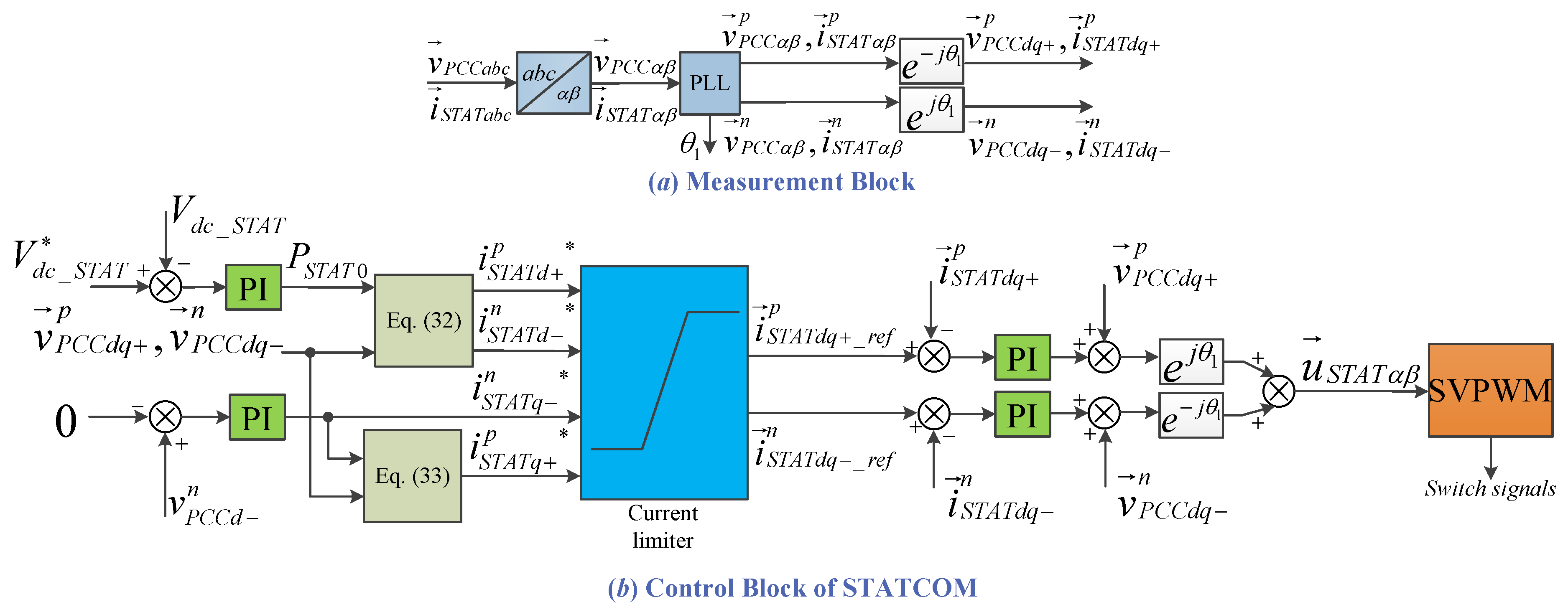
The control diagram of STATCOM is shown in Figure 7. The control priority of STATCOM is implemented by designing the current limiter in Figure 7b. Specifically, the control of active currents has a higher priority than that of the reactive currents, as shown in Figure 8.
Figure 7. Voltage compensation control scheme of STATCOM.
Energies 06 04660 g007
Figure 8. Calculation algorithm for the STATCOM current references.
Energies 06 04660 g008
Neglecting the internal power dissipation of STATCOM, there is i S T A T d + p = i S T A T d - n = 0 under the steady-state; thus the current capacity of STATCOM is mainly used to compensate for the imbalance of the PCC voltage. Since the STATCOM aims to reduce the unbalanced degree of PCC voltage into the controllable regions of DFIG-based WECS under severe asymmetrical fault situations, it is necessary to confirm the minimum capacity required for the STATCOM.
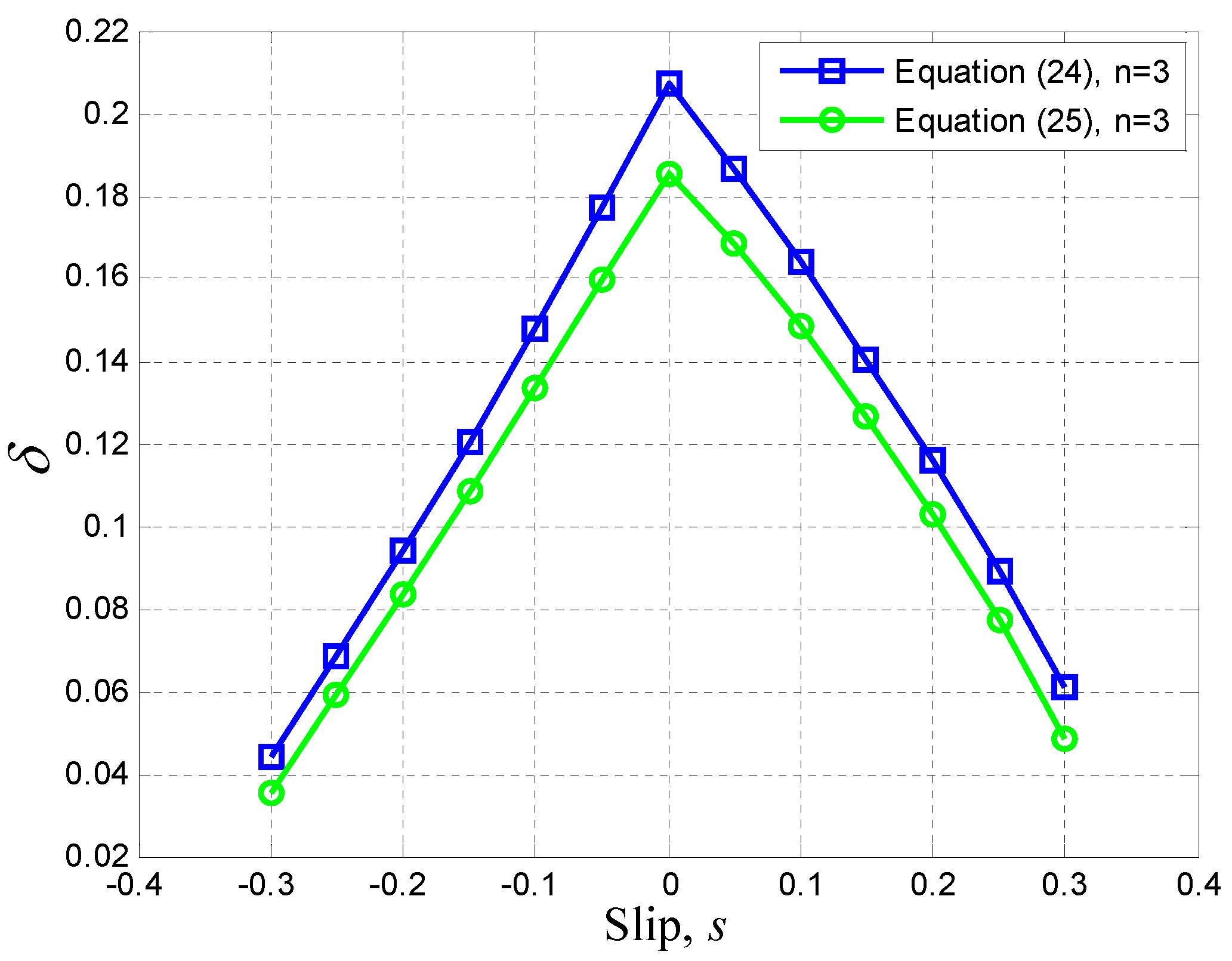
Suppose that the unbalanced degree of PCC voltage before compensation is:
0 < δ max < v P C C d - n v P C C d + p 1
where the δ max is given by solving Equation (25).
To ensure the DFIG-based WECS stay controllable, the voltage compensation target of STATCOM should be set as:
0 < v P C C d - n - ω s L L i S T A T q - n v P C C d + p + ω s L L i S T A T q + p δ max
Combining Equation (33), the capacity minimization problem of STATCOM can be formulated as a nonlinear programming problem, as in Equation (36):
min ( i S T A T q + p + i S T A T q - n ) 0 < δ max < v P C C d - n v P C C d + p 1 0 < v P C C d - n - ω s L L i S T A T q - n v P C C d + p + ω s L L i S T A T q + p δ max i S T A T q + p = k v P C C d + p + ω s L L i S T A T q + p v P C C d - n - ω s L L i S T A T q - n i S T A T q - n i S T A T q + p 0 , i S T A T q - n 0
The calculated results of the above problem is:
i S T A T q + p = k ( v P C C d - n - δ max v P C C d + p ) ( 1 + k ) δ max ω s L L i S T A T q - n = v P C C d - n - δ max v P C C d + p ( 1 + k ) ω s L L ( i S T A T q + p + i S T A T q - n ) min = ( k + δ max ) ( v P C C d - n - δ max v P C C d + p ) ( 1 + k ) δ max ω s L L
Q S T A T r a t e _ min = 3 2 V P C C p r e I S T A T r a t e _ min = 3 2 V P C C p r e · ( k + δ max ) ( v P C C d - n - δ max v P C C d + p ) ( 1 + k ) δ max ω s L L
where V P C C p r e is the PCC voltage magnitude before gird faults.
From Equation (38), it is easy to find out that the minimum capacity required for the STATCOM increases monotonically with k. As a result, how to choose k comes to be a trade-off between mitigating oscillations on the DC-link voltage of STATCOM and reducing the needed capacity of STATCOM. Consequently, in engineering applications, k can be selected according to the tolerated maximum voltage fluctuation of the DC-link capacitor.
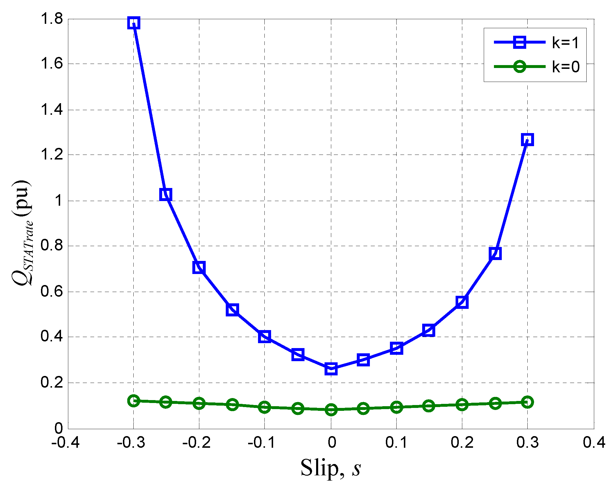
A numerical example is given for Equation (38) as follows. According to Figure 5, with the δ max [Equation (25), n = 3 ] given in Table 3 and ( v P C C d + p = 2 V P C C p r e / 3 , v P C C d - n = V P C C p r e / 3 , L l = 4 . 725 mH/km), the needed capacity of STATCOM with various k is the area above its corresponding line in Figure 9, and the Q S T A T r a t e _ min is given in Table 4 (capacity base value is 9 Mvar).
Figure 9. Capacity matching of STATCOM through DFIG’s operative slip range.
Energies 06 04660 g009
Table 4. Minimum capacity required for the STATCOM with different slips.
Slip s−0.3−0.2−0.100.10.20.3
Q S T A T r a t e _ min (pu) ( k = 0 )0.12080.10830.09520.08180.09140.10320.1173
Q S T A T r a t e _ min (pu) ( k = 1 )1.78160.70420.40360.26140.35330.55371.2684

5. Simulation Verifications

The simulations are intended to verify the effectiveness of the proposed control schemes for DFIG-based WECS and STATCOM during asymmetrical grid faults, as well as the accuracy of the DFIG-based WECS’s controllable regions derived in Section 3 and the STATCOM’s capacity matching method derived in Section 4.
The typical diagram of the power system integrated with the wind farm presented in Figure 5 is implemented by MATLAB/SIMULINK. The wind farm is simulated as a lumped 9 MW DFIG model containing six DFIGs, each rated at 1.5 MW. The parameters of the single DFIG system follow Table 1 and Table 2. Initially, the DFIG is under vector control in super-synchronous operation ( s = - 0 . 1 ), while the stator output active power is 1 pu with the unity power factor. The grid fault occurs at the GCP when t = 1 s. After that, the insulated gate bipolar transistors (IGBTs) of RSC are blocked, and the rotor crowbar is used to ride-through the first period of LVRT, which lasts 20 ms, according to the German grid code [2,3]; after t = 1 . 02 s, it enters the second period of LVRT, the crowbar is cut off and RSC recovers the control of DFIG. In this simulation, the STATCOM is modeled as a gate turn-off thyristor (GTO) pulse-width modulation (PWM) converter with a DC-link capacitor. Since the whole simulation model contains many modules, the RSC, GSC and STATCOM are all implemented by their mathematical models instead of their circuit-based models, so as to achieve fast simulations. It needs to be noted that the simulations are realized under the following assumptions:
(i) Assuming that the crowbar is triggered once the grid voltage drop occurs, since the interval between the occurrence of the grid voltage drop and the crowbar cut-in is just a few milliseconds.
(ii) Assuming that the DFIG speed does not change during the grid faults, since the inertia of a MW-class wind turbine is very large and the time duration of the grid faults is very short.
Two different scenarios are examined in this section:
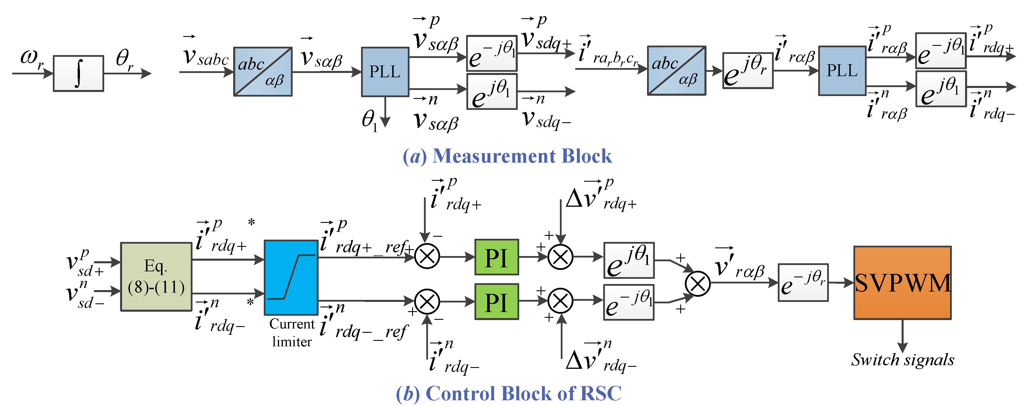
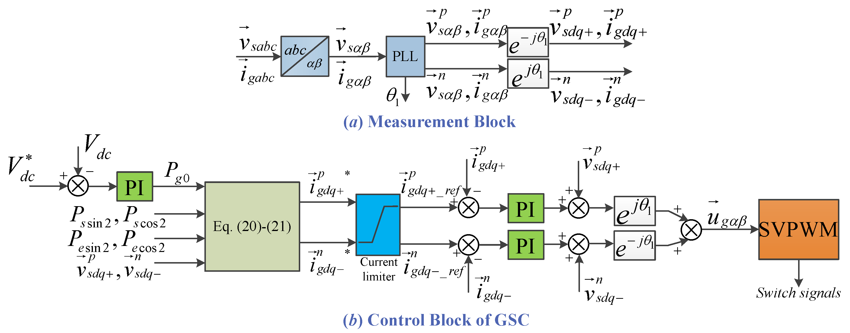
(i) Case 1: the proposed control schemes for RSC and GSC shown in Figure 1 and Figure 2 are employed to control the DFIG-based wind farm in the second period of LVRT without STATCOM compensation. The simulation results in three situations are shown in 
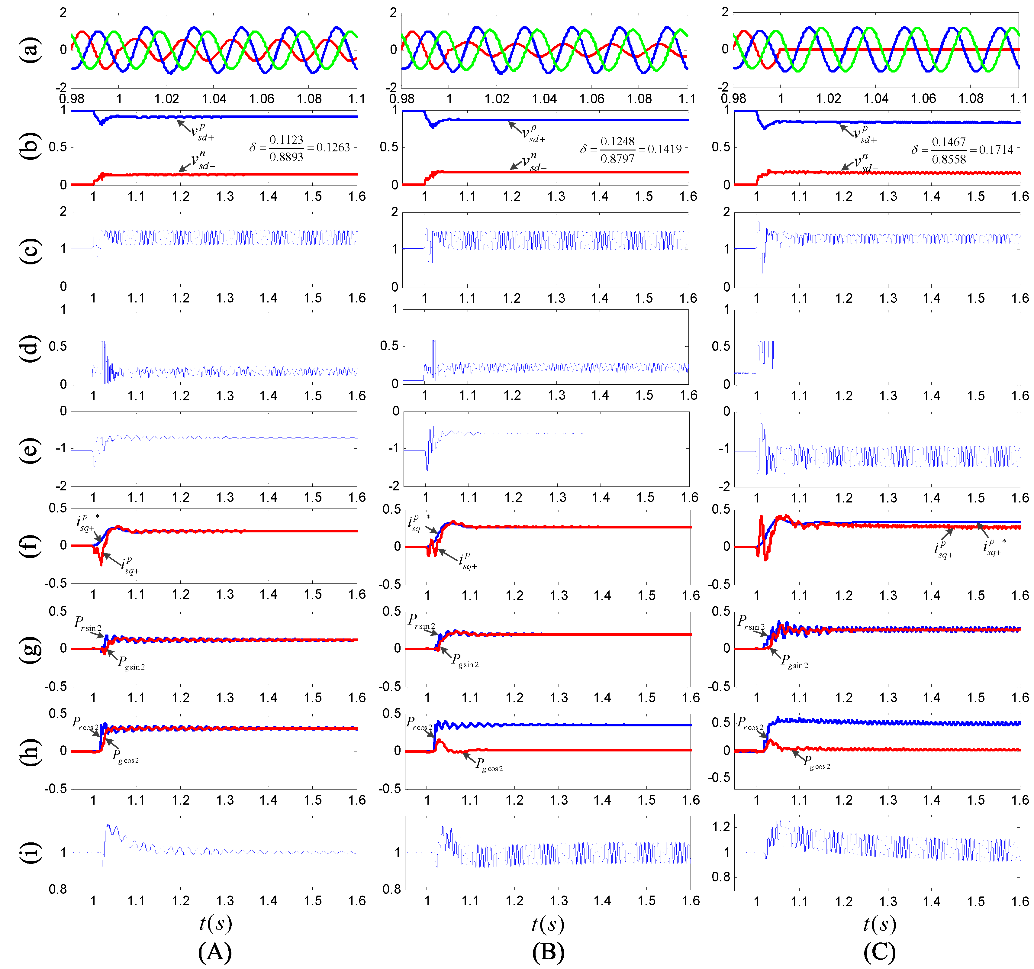
Figure 10, and the following conclusions can be drawn from this figure.
Figure 10. Simulation results of the DFIG-based wind farm without STATCOM compensation during asymmetrical grid faults: (a) three-phase voltages at GCP (pu); (b) magnitudes of positive- and negative-sequence stator voltages (pu); (c) magnitude of rotor current space vector | i r α β | (pu); (d) magnitude of rotor voltage space vector | v r α β | (pu); (e) electromagnetic torque T e (pu); (f) positive-sequence stator reactive current (pu); (g) and (h): magnitudes of active power oscillations on both sides of the DFIG system’s DC-bus (pu); and (i) the DC-link voltage of DFIG system V d c (pu). (A) single-phase resistance-grounded fault (grounding resistance R f = 6 Ω ); (B) single-phase resistance-grounded fault (grounding resistance R f = 3 Ω ); and (C) single-phase solidly-grounded fault.
Energies 06 04660 g010
(1) It can be seen from Figure 10c that, in the first period of LVRT (1 s∼ 1 . 02 s), the rotor transient surge current can be restrained below 2 pu with the help of a rotor crowbar, which achieves the safe operation of the converter in this period.
(2) In situation (A), since the unbalanced degree of the stator voltage (Figure 10A:b) is within the derived controllable region of DFIG-based WECS according to Table 3, i.e., δ = 0 . 1263 < δ max = 0 . 1337 [Equation (25), n = 3 , s = - 0 . 1 ], the control targets of both RSC and GSC can be achieved. Specifically, the oscillations on the electromagnetic torque can be eliminated (Figure 10A:e), the positive-sequence stator reactive current can meet the LVRT grid code requirement (Figure 10A:f) and there are no oscillations on the DC-link voltage of the DFIG system (Figure 10A:i).
(3) When the grid fault becomes more severe as in situation (B), there is δ max = 0 . 1337 [Equation (25), n = 3 , s = - 0 . 1 ] < δ = 0 . 1419 < δ max = 0 . 1480 [Equation (24), n = 3 , s = - 0 . 1 ], which means that the control target of GSC can no longer be achieved, but the DFIG is still controllable. As a result, the GSC has no sufficient current capacity to transfer the rotor-side active power oscillations to the grid (Figure 10B:h), which results in the oscillations on the DC-link voltage of the DFIG system (Figure 10B:i).
(4) Furthermore, when δ = 0 . 1714 > δ max = 0 . 1480 [Equation (24), n = 3 , s = - 0 . 1 ] as in situation (C), even the DFIG becomes uncontrollable. As a result, the output voltage of RSC (Figure 10C:d) presents over-modulation, which results in the oscillations on electromagnetic torque (Figure 10C:e) and the non-compliance of the positive-sequence stator reactive current (Figure 10C:f).
Consequently, the above simulation results can validate the accuracy of the DFIG-based WECS’s controllable regions derived in Section 3 and the effectiveness of the proposed control scheme for DFIG-based WECS within its controllable regions.
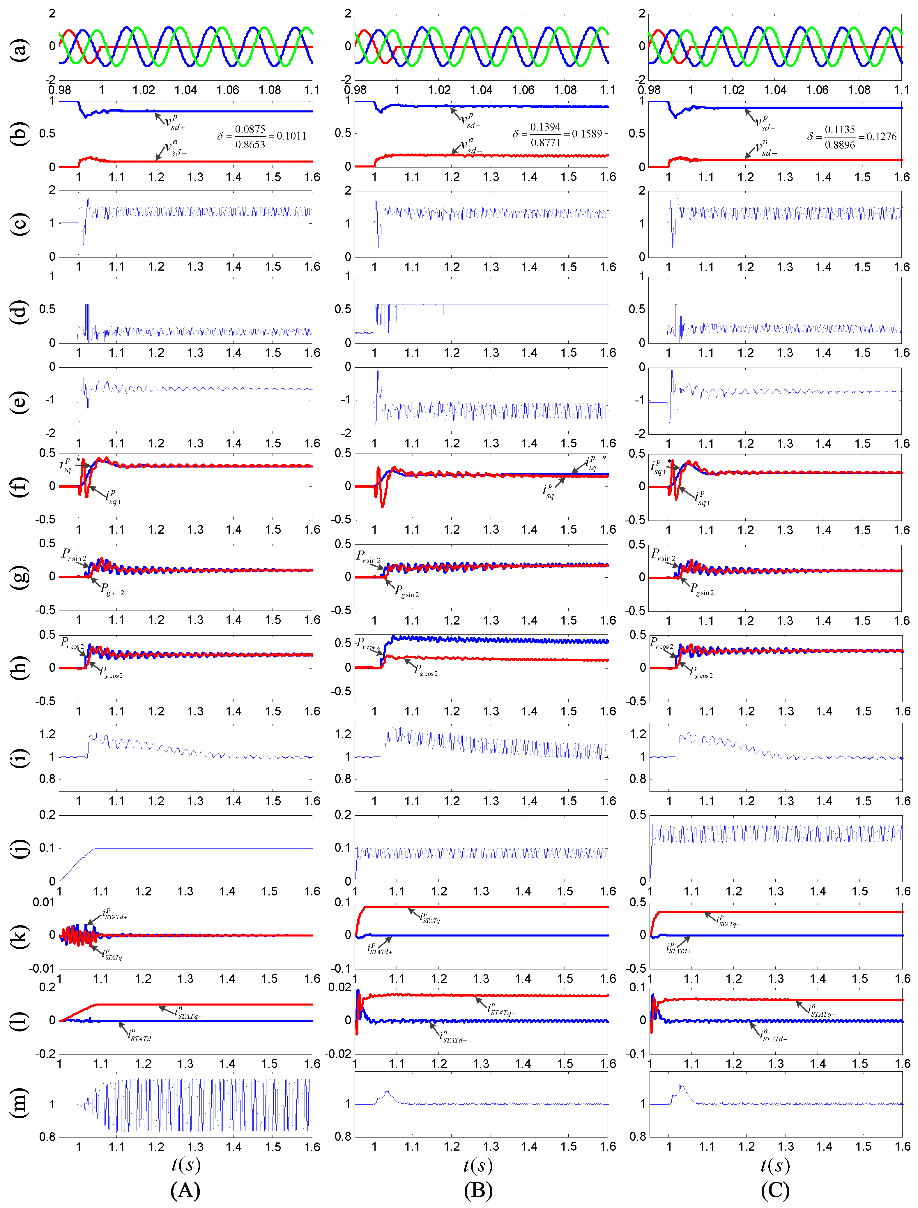
(ii) Case 2: the proposed control scheme shown in Figure 7 is employed to control the STATCOM for the purpose of improving the asymmetrical LVRT capability of the DFIG-based wind farm. The simulation results in three situations are shown in Figure 11, and the following conclusions can be drawn from this figure.
(1) Comparing Figure 11A with Figure 10C, it can be seen that, with the help of voltage compensation supplied by a STATCOM having sufficient capacity, i.e., Q S T A T r a t e = 0 . 1 pu > Q S T A T r a t e _ m i n = 0 . 0952 pu ( k = 0 , s = - 0 . 1 ) according to Table 4, the unbalanced degree of the stator voltage can be reduced from 0.1714 to 0.1011. This means that the DFIG-based WECS gets into its controllable regions [ δ = 0 . 1011 < δ max = 0 . 1337 (Equation (25), n = 3 , s = - 0 . 1 )]. Therefore, the control targets of both RSC and GSC can be achieved again in this situation. However, since all the current capacity of STATCOM is used to compensate for the negative-sequence PCC voltage (Figure 11A:k–l), it may cause large oscillations on the DC-link voltage of STATCOM (Figure 11A:m).
Figure 11. Simulation results of the DFIG-based wind farm with STATCOM compensation during asymmetrical grid faults: (a) three-phase voltages at GCP (pu); (b) magnitudes of positive- and negative-sequence stator voltages (pu); (c) magnitude of rotor current space vector | i r α β | (pu); (d) magnitude of rotor voltage space vector | v r α β | (pu); (e) electromagnetic torque T e (pu); (f) positive-sequence stator reactive current (pu); (g) and (h): magnitudes of active power oscillations on both sides of the DFIG system’s DC-bus (pu); (i) DC-link voltage of DFIG system V d c (pu); (j) magnitude of STATCOM current space vector | i S T A T α β | (pu); (k) positive-sequence components of STATCOM current (pu); (l) negative-sequence components of STATCOM current (pu); and (m) the DC-link voltage of STATCOM V d c _ S T A T (pu). (A) single-phase solidly-grounded fault ( Q S T A T r a t e = 0 . 1 pu, k = 0 ); (B) single-phase solidly-grounded fault ( Q S T A T r a t e = 0 . 1 pu, k = 1 ); and (C) single-phase solidly-grounded fault ( Q S T A T r a t e = 0 . 42 pu, k = 1 ).
Energies 06 04660 g011
(2) Comparing Figure 11B with Figure 11A, as the capacity of STATCOM (0.1 pu) is assigned between its positive- and negative-sequence reactive currents following Equation (33) in which k = 1 (Figure 11B:k–l), the oscillations on the DC-link voltage of STATCOM can be eliminated (Figure 11B:m). However, for k = 1 , it needs a STATCOM rated at least 0.4036 pu to ensure that the DFIG-based wind farm stays controllable according to Table 4. As a result, a STATCOM rated at 0.1 pu is insufficient to reduce the unbalanced degree of stator voltage into its controllable regions [ δ = 0 . 1589 > δ max = 0 . 1480 (Equation (24), n = 3 , s = - 0 . 1 )]; thus the control targets of both RSC and GSC can no longer be achieved in this situation.
(3) Furthermore, comparing Figure 11C with Figure 11B, the capacity of STATCOM is increased to 0.42 pu, which is larger than 0.4036 pu. As a result, the STATCOM is sufficient to reduce the unbalanced degree of the stator voltage into the controllable region of DFIG-based WECS [ δ = 0 . 1276 < δ max = 0 . 1337 (Equation (25), n = 3 , s = - 0 . 1 )], while eliminating the oscillations on the DC-link voltage itself. Thus, in this situation, the control targets of both RSC and GSC can be achieved again.
Consequently, the above simulation results can validate the effectiveness of the proposed control scheme for STATCOM during asymmetrical LVRT and the accuracy of the corresponding capacity matching method derived in Section 4.

6. Conclusions

This paper has discussed the coordinated control of a DFIG-based wind farm and a STATCOM for LVRT grid code compliance during asymmetrical grid faults. Simulations on a 9 MW DFIG-based wind farm are performed to validate the proposed control strategy. As a result, the following conclusions can be drawn:
(1) The control scheme for a DFIG-based WECS is designed by taking the LVRT grid code into consideration; the controllability of a DFIG-based WECS with the proposed control scheme is analyzed by means of the optimal method. The derived controllable regions indicate that a DFIG-based WECS can only remain controllable under mild asymmetrical fault situations, and the GSC rating is the primary explanation for this limitation.
(2) A STATCOM is introduced as assistive equipment to ensure that the DFIG-based wind farm remains controllable under severe asymmetrical fault situations. To reduce the unbalanced degree of fault voltage while mitigating the oscillations on the DC-link voltage of the STATCOM, a voltage compensation control scheme for the STATCOM is designed. In addition, the capacity matching method of the STATCOM is given, which indicates that a trade-off exists between mitigating the oscillations on the DC-link voltage of the STATCOM and reducing the needed capacity of the STATCOM.
The proposed coordinated control strategy can guarantee that a DFIG-based wind farm will supply the positive-sequence reactive current defined by the LVRT grid code with safe grid-connected operation. This improves the reliability of both the wind farm and the power system during grid faults. Moreover, the outcome of the analysis in this paper may also be interesting for evaluating the asymmetrical LVRT capability of DFIG-based WECS and for designing extra assistive equipment for the LVRT of a DFIG-based wind farm.

Acknowledgments

The authors would like to thank the support from the National Natural Science Foundation of China (No. 61273045 and 61104046), Tsinghua University Initiative Scientific Research Program (20111081065) and the Power Electronics Science and Education Development Program of Delta Environmental and Educational Foundation (DREK-2010003).

Conflicts of Interest

The authors declare no conflict of interest.

References

  1. Tsili, M.; Papathanassiou, S. A review of grid code technical requirements for wind farms. IET Renew. Power Gener. 2009, 3, 308–332. [Google Scholar] [CrossRef]
  2. Berndt, H.; Hermann, M.; Kreye, H.D.; Reinisch, R.; Scherer, U.; Vanzetta, J. TransmissionCode 2007: Network and System Rules of the German Transmission System Operators; Verband der Netzbetreiber-VDN-e.v.beim VDEW: Berlin, Germany, 2007; Available online: http://www.vdn-berlin.de (accessed on 16 July 2013).
  3. Federal Ministry for the Environment. Ordinance on System Services by Wind Energy Plants (System Service Ordinance-SDLWindV); Nature Conservation and Nuclear Safety: Bonn, Germany, 2009; Available online: http://www.erneuerbareenergien.de (accessed on 16 July 2013).
  4. Wu, B.; Lang, Y.; Zargari, N.; Kouro, S. Power Conversion and Control of Wind Energy Systems; Wiley: New York, NY, USA, 2011. [Google Scholar]
  5. Xiang, D.W.; Ran, L.; Tavner, P.J.; Yang, S. Control of a doubly fed induction generator in a wind turbine during grid fault ride-through. IEEE Trans. Energy Convers. 2006, 21, 652–662. [Google Scholar] [CrossRef]
  6. Lopez, J.; Sanchis, P.; Roboam, X.; Marroyo, L. Dynamic behavior of the doubly fed induction generator during three-phase voltage dips. IEEE Trans. Energy Convers. 2007, 22, 709–717. [Google Scholar] [CrossRef]
  7. Lopez, J.; Gubia, E.; Sanchis, P.; Roboam, X.; Marroyo, L. Wind turbines based on doubly fed induction generator under asymmetrical voltage dips. IEEE Trans. Energy Convers. 2008, 23, 321–330. [Google Scholar] [CrossRef]
  8. Geng, H.; Liu, C.; Yang, G. LVRT capability of DFIG based WECS under asymmetrical grid fault condition. IEEE Trans. Ind. Electron. 2013, 60, 2495–2509. [Google Scholar] [CrossRef]
  9. Liang, J.; Qiao, W.; Harley, R.G. Feed-forward transient current control for low-voltage ride-through enhancement of DFIG wind turbines. IEEE Trans. Energy Convers. 2010, 25, 836–843. [Google Scholar] [CrossRef]
  10. Lima, F.K.A.; Luna, A.; Rodriguez, P.; Watanabe, E.H.; Blaabjerg, F. Rotor voltage dynamics in the doubly fed induction generator during grid faults. IEEE Trans. Power Electron. 2010, 25, 118–130. [Google Scholar] [CrossRef] [Green Version]
  11. Mohseni, M.; Masoum, M.A.S.; Islam, S.M. Fault ride-through capability enhancement for doubly fed induction wind generators. IET Renew. Power Gener. 2011, 5, 368–378. [Google Scholar] [CrossRef]
  12. Hu, S.; Lin, X.; Kang, Y.; Zou, X. An improved low-voltage ride-through control strategy of doubly fed induction generator during grid faults. IEEE Trans. Power Electron. 2011, 26, 3653–3665. [Google Scholar] [CrossRef]
  13. Xiao, S.; Yang, G.; Zhou, H.; Geng, H. A LVRT control strategy based on flux linkage tracking for DFIG-based WECS. IEEE Trans. Ind. Electron. 2013, 60, 2820–2832. [Google Scholar] [CrossRef]
  14. Xiao, S.; Geng, H.; Zhou, H.; Yang, G. Analysis of the control limit for rotor-side converter of doubly fed induction generator-based wind energy conversion system under various voltage dips. IET Renew. Power Gener. 2013, 7, 71–81. [Google Scholar] [CrossRef]
  15. Morren, J.; de Haan, S.W.H. Ridethrough of wind turbines with doubly-fed induction generator during a voltage dip. IEEE Trans. Energy Convers. 2005, 20, 435–441. [Google Scholar] [CrossRef]
  16. Lopez, J.; Gubia, E.; Olea, E.; Ruiz, J.; Marroyo, L. Ride through of wind turbines with doubly fed induction generator under symmetrical voltage dips. IEEE Trans. Ind. Electron. 2009, 56, 4246–4254. [Google Scholar] [CrossRef]
  17. Morren, J.; de Haan, S.W.H. Short-circuit current of wind turbines with doubly fed induction generator. IEEE Trans. Energy Convers. 2007, 22, 174–180. [Google Scholar] [CrossRef]
  18. Zhou, H.L.; Yang, G.; Li, D.Y. Short Circuit Current Analysis of DFIG Wind Turbines with Crowbar Protection. In Proceedings of the International Conference on Electrical Machines and Systems (ICEMS 2009), Tokyo, Japan, 15–18 November 2009; pp. 1–6.
  19. Teninge, A.; Roye, D.; Bacha, S. Reactive Power Control for Variable Speed Wind Turbines to Low Voltage Ride through Grid Code Compliance. In Proceedings of the International Conference on Electrical Machines (ICEM 2010), Rome, Italy, 6–8 September 2010; pp. 1–6.
  20. Muljadi, E.; Yildirim, D.; Batan, T.; Butterfield, C.P. Understanding the Unbalanced-Voltage Problem in Wind Turbine Generation. In Proceedings of the 34th Annual Conference of IEEE Industry Applications Society (IAS 1999), Phoenix, AZ, USA, 3–7 October 1999; pp. 1359–1365.
  21. Codd, I. Windfarm Power Quality Monitoring and Output Comparison with EN50160. In Proceedings of the 4th International Workshop on Large-Scale Integration of Wind Power and Transmission Networks for Offshore Wind Farms, Billund, Denmark, 20–21 October 2003.
  22. Xu, L.; Wang, Y. Dynamic modeling and control of DFIG-based wind turbines under unbalanced network conditions. IEEE Trans. Power Syst. 2007, 22, 314–323. [Google Scholar] [CrossRef]
  23. Brekken, T.K.A.; Mohan, N. Control of a doubly fed induction wind generator under unbalanced grid voltage conditions. IEEE Trans. Energy Convers. 2007, 22, 129–135. [Google Scholar] [CrossRef]
  24. Xu, L. Coordinated control of DFIG’s rotor and grid side converters during network unbalance. IEEE Trans. Power Electron. 2008, 23, 1041–1049. [Google Scholar]
  25. Xu, L. Enhanced control and operation of DFIG-based wind farms during network unbalance. IEEE Trans. Energy Convers. 2008, 23, 1073–1081. [Google Scholar] [CrossRef]
  26. Hu, J.; He, Y.; Xu, L.; Williams, B.W. Improved control of DFIG systems during network unbalance using PI-R current regulators. IEEE Trans. Ind. Electron. 2009, 56, 439–451. [Google Scholar] [CrossRef]
  27. Hu, J.; He, Y. Modeling and enhanced control of DFIG under unbalanced grid voltage conditions. Electr. Power Syst. Res. 2009, 79, 273–281. [Google Scholar] [CrossRef]
  28. Hu, J.; Nian, H.; Xu, H.; He, Y. Dynamic modeling and improved control of DFIG under distorted grid voltage conditions. IEEE Trans. Energy Convers. 2011, 26, 163–175. [Google Scholar] [CrossRef]
  29. Hu, J.; He, Y. DFIG wind generation systems operating with limited converter rating considered under unbalanced network conditions—Analysis and control design. Renew. Energy 2011, 36, 829–847. [Google Scholar] [CrossRef]
  30. Martinez, M.I.; Tapia, G.; Susperregui, A.; Camblong, H. DFIG power generation capability and feasibility regions under unbalanced grid voltage conditions. IEEE Trans. Energy Convers. 2011, 26, 1051–1062. [Google Scholar] [CrossRef]
  31. Piwko, R.; Miller, N.; Sanchez-Gasca, J.; Yuan, X.; Dai, R.; Lyons, J. Integrating Large Wind Farms into Weak Power Grids with Long Transmission Lines. In Proceedings of the International Conference on Power Electronics and Motion Control (IPEMC 2006), Shanghai, China, 14–16 August 2006; pp. 1–7.
  32. Qiao, W.; Harley, R.G. Power Quality and Dynamic Performance Improvement of Wind Farms Using a STATCOM. In Proceedings of the IEEE Power Electronics Specialists Conference (PESC 2007), Atlanta, GA, USA, 17–21 June 2007; pp. 1832–1838.
  33. Qiao, W.; Venayagamoorthy, G.K.; Harley, R.G. Real-time implementation of a STATCOM on a wind farm equipped with doubly fed induction generators. IEEE Trans. Ind. Appl. 2009, 45, 98–107. [Google Scholar] [CrossRef]
  34. Qiao, W.; Harley, R.G.; Venayagamoorthy, G.K. Coordinated reactive power control of a large wind farm and a STATCOM using heuristic dynamic programming. IEEE Trans. Energy Convers. 2009, 24, 493–503. [Google Scholar] [CrossRef]
  35. Teodorescu, R.; Liserre, M.; Rodriguez, P. Grid Converters for Photovoltaic and Wind Power Systems; Wiley: New York, NY, USA, 2011. [Google Scholar]
  36. Geng, H.; Xu, D.; Wu, B. A novel hardware-based all-digital phase-locked loop applied to grid-connected power converters. IEEE Trans. Ind. Electron. 2011, 58, 1737–1745. [Google Scholar] [CrossRef]
  37. Zheng, Z.; Yang, G.; Geng, H. Capability of Asymmetrical Grid Faults Ride-through for DFIG-Based Wind Turbines. In Proceedings of the 38th Annual Conference of the IEEE Industrial Electronics Society (IECON 2012), Montreal, QC, Canada, 25–28 October 2012; pp. 3533–3540.
  38. Bollen, M.H.J. Understanding Power Quality Problems: Voltage Sags and Interruptions; Wiley: New York, NY, USA, 2002. [Google Scholar]
  39. Mohseni, M.; Islam, S.M.; Masoum, M.A.S. Impacts of symmetrical and asymmetrical voltage sags on DFIG-based wind turbines considering phase-angle jump, voltage recovery, and sag parameters. IEEE Trans. Power Electron. 2011, 26, 1587–1598. [Google Scholar] [CrossRef]
  40. Wang, Y.; Xu, L.; Williams, B.W. Compensation of network voltage unbalance using doubly fed induction generator-based wind farms. IET Renew. Power Gener. 2009, 3, 12–22. [Google Scholar] [CrossRef]

