Recycle Effect on Device Performance of Wire Mesh Packed Double-Pass Solar Air Heaters

Abstract
:1. Introduction
2. Mathematical Modeling


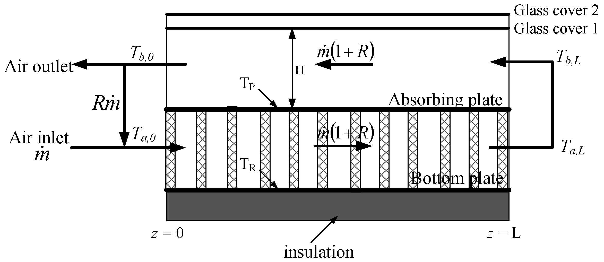
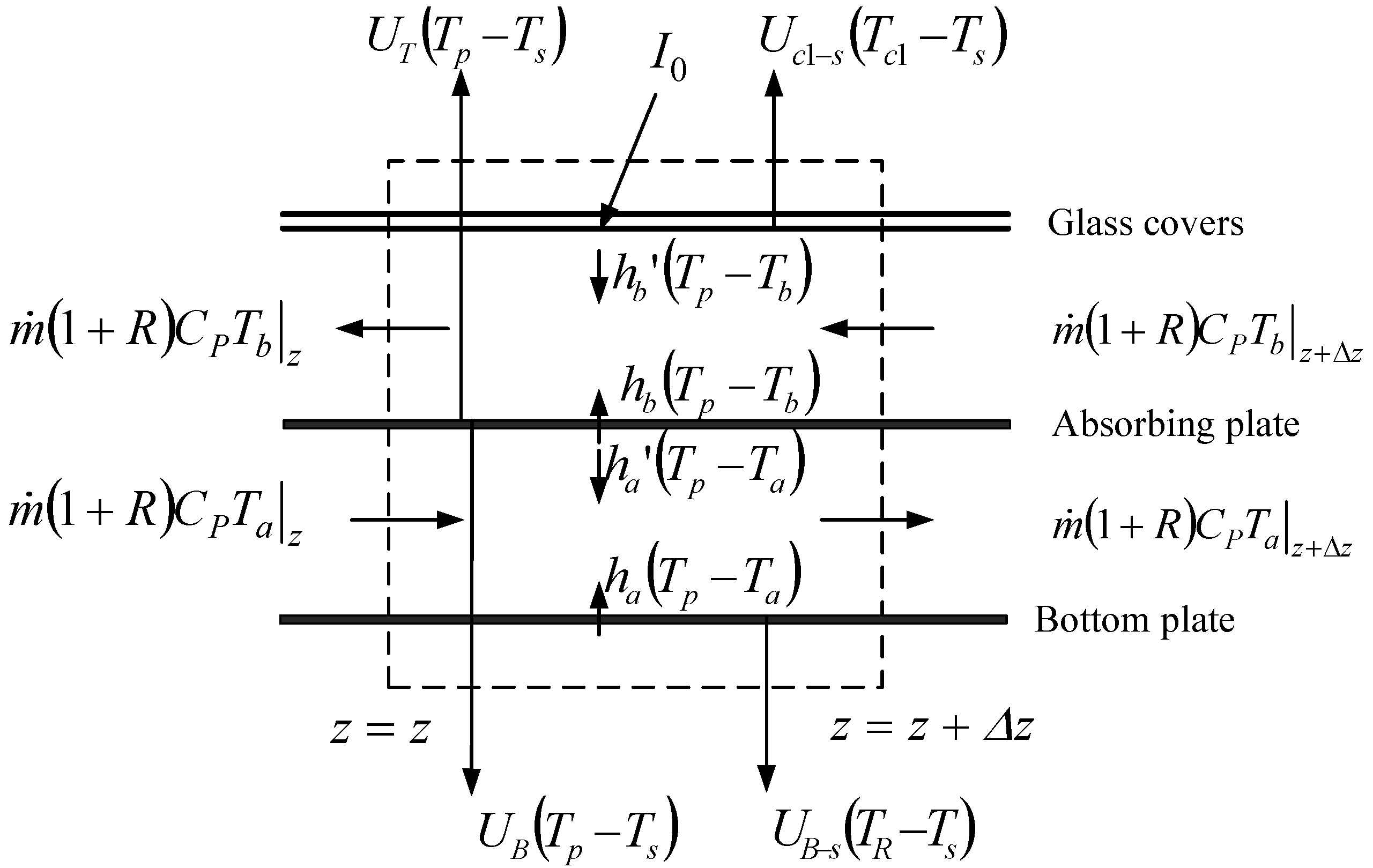
2.1. Temperature Distributions on Wire Mesh Packed Solar Air Heaters
2.2. Heat Transfer Coefficients of Wire Mesh Packing
2.3. Heat Transfer Coefficients and Collector Efficiency Improvement

| Parameters | Operation parameters | Physical properties | |||
|---|---|---|---|---|---|
| Ac (m2) | 0.09 | (kg/s) | 0.0107, 0.0161, 0.0214 | αP | 0.96 |
| H (m) | 0.05 | Tin (°C) | 20, 30, 40 | εσ | 0.94 |
| L (m) | 0.3 | Ts (°C) | 20 ± 0.1 | εP | 0.8 |
| W (m) | 0.3 | I0 (W/m2) | 830 ± 20, 1100 ± 20 | εR | 0.94 |
| l (m) | 0.015 | V (m/s) | 1.0 | τσ | 0.875 |
| – | – | ks (W/m·K) | 0.033 | ||
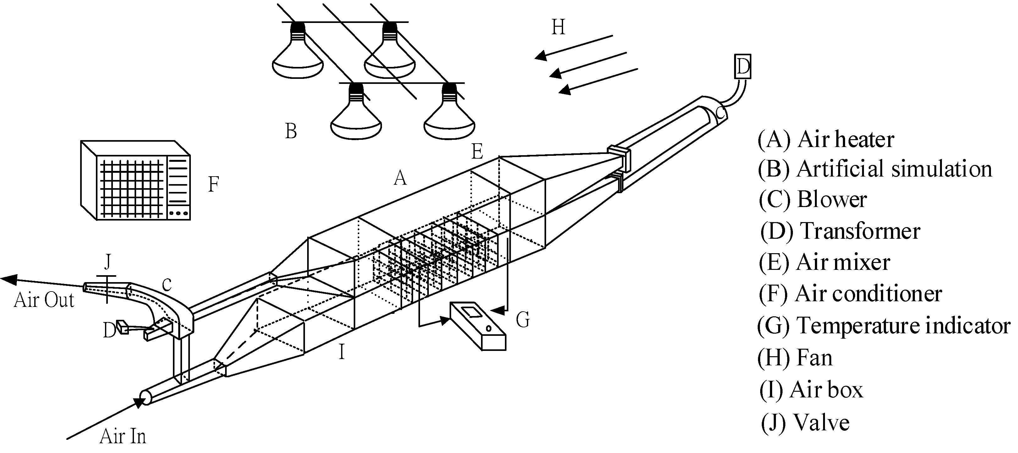
3. Experimental Procedure

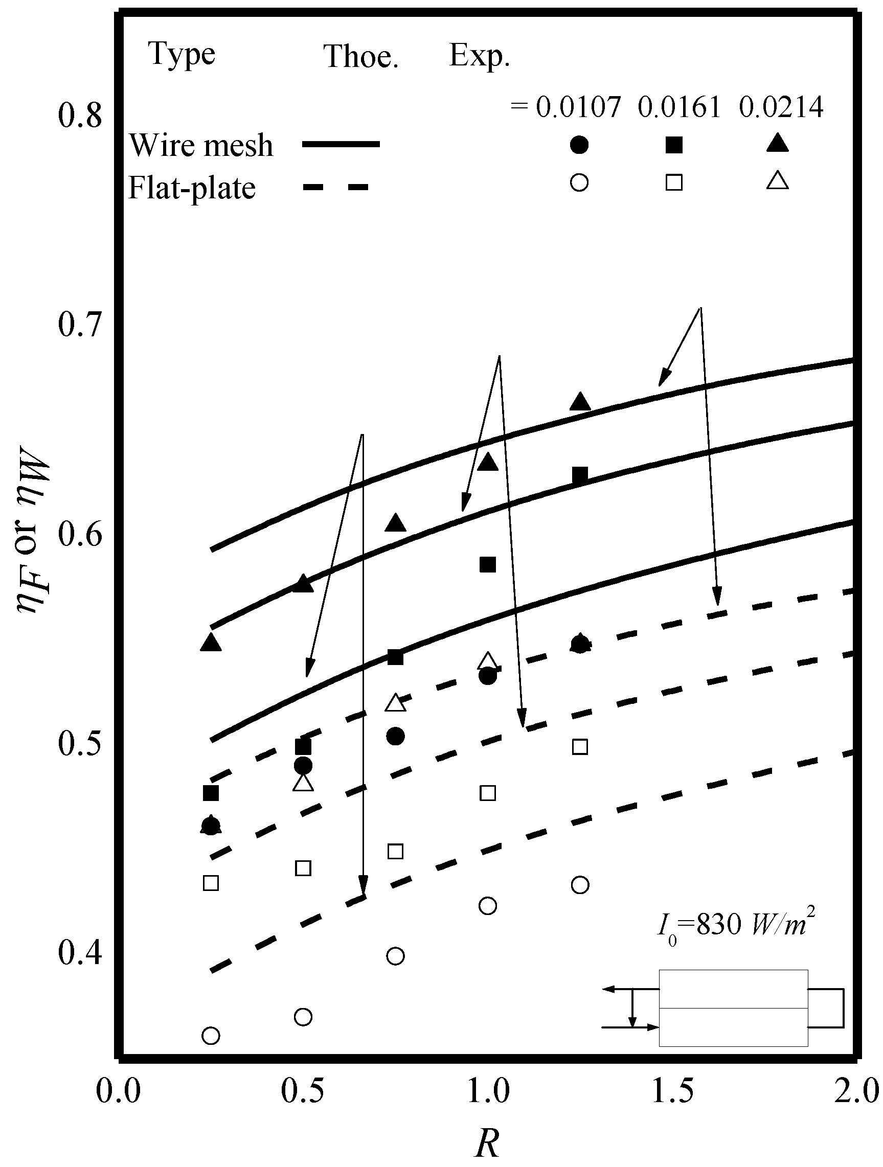
4. Results and Discussion

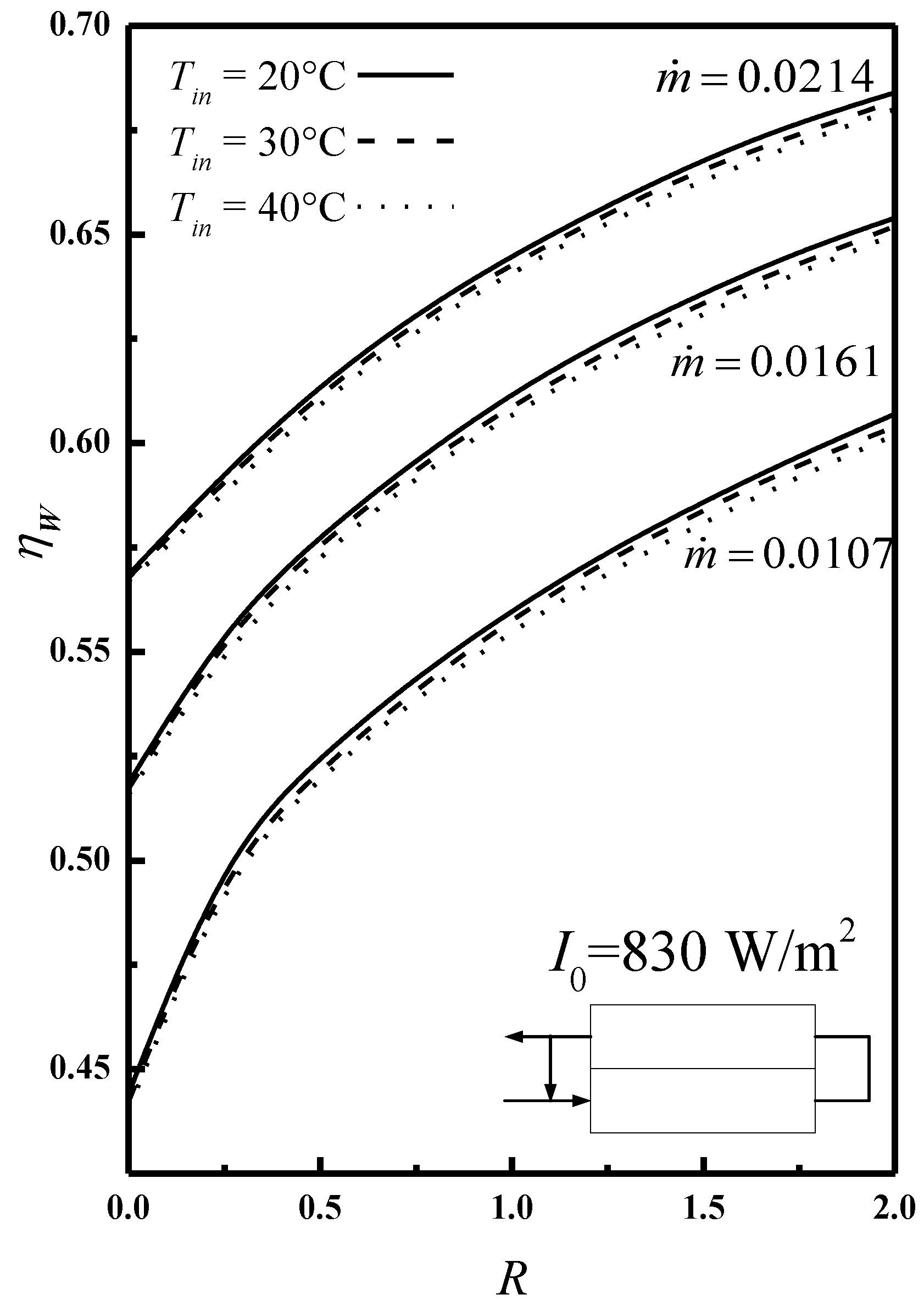
| (kg/s) | R | I0 = 830 (W/m2) | I0 = 1100 (W/m2) | ||
|---|---|---|---|---|---|
| Flat-plate | Wire mesh | Flat-plate | Wire mesh | ||
| ηF | ηW | ηF | ηW | ||
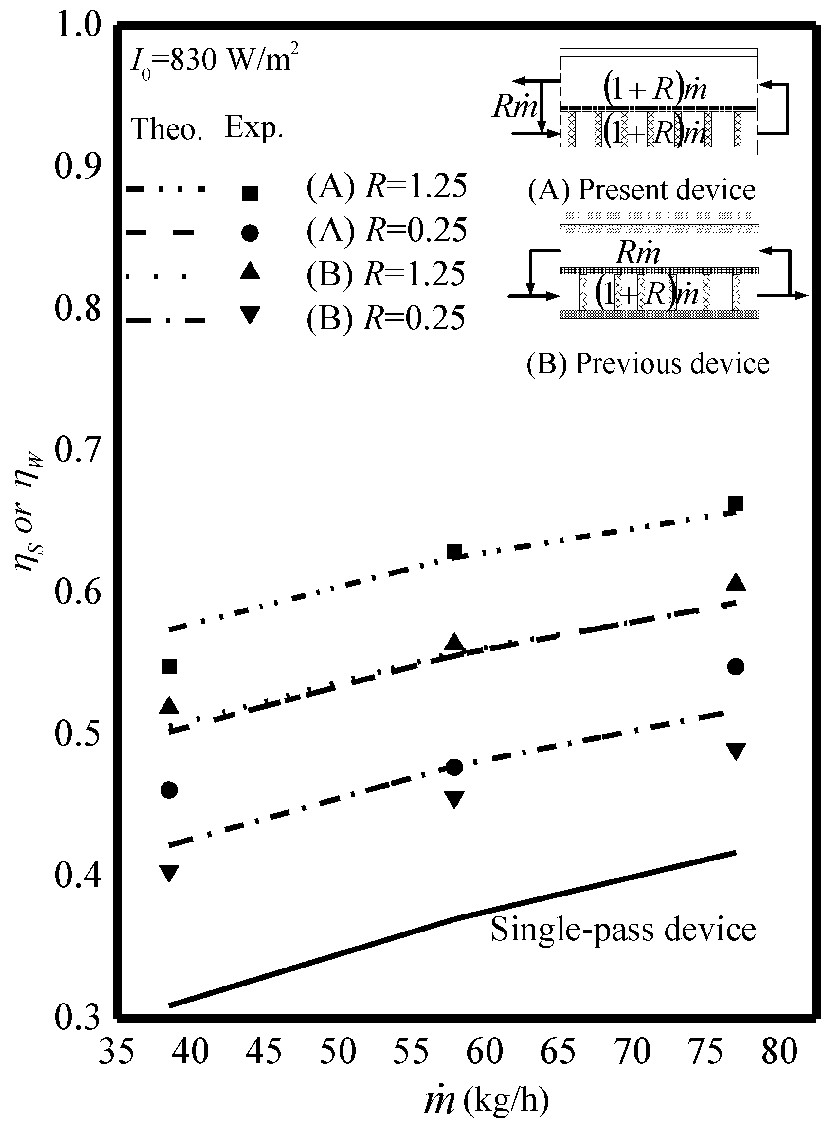
| 0.0107 | 0.5 | 0.415 | 0.525 | 0.417 | 0.527 |
| 1 | 0.450 | 0.560 | 0.452 | 0.562 | |
| 1.5 | 0.476 | 0.586 | 0.478 | 0.588 | |
| 2 | 0.497 | 0.607 | 0.498 | 0.608 | |
| 0.0161 | 0.5 | 0.468 | 0.578 | 0.470 | 0.580 |
| 1 | 0.502 | 0.612 | 0.503 | 0.613 | |
| 1.5 | 0.526 | 0.636 | 0.527 | 0.637 | |
| 2 | 0.544 | 0.654 | 0.545 | 0.655 | |
| 0.0214 | 0.5 | 0.504 | 0.614 | 0.506 | 0.616 |
| 1 | 0.535 | 0.645 | 0.537 | 0.647 | |
| 1.5 | 0.558 | 0.668 | 0.558 | 0.668 | |
| 2 | 0.574 | 0.684 | 0.575 | 0.685 | |
| Accuracy | ||||
|---|---|---|---|---|
| Flat-plate | Wire mesh | |||
| (kg/s) | 830 | I0 (W/m2) 1100 | 830 | 1100 |
| 0.0107 | 1.58 | 5.38 | 4.27 | 0.85 |
| 0.0161 | 5.09 | 5.92 | 9.44 | 5.15 |
| 0.0214 | 2.50 | 3.56 | 6.64 | 5.75 |
| m (kg/s) | R | I0 = 830 (W/m2) | I0 = 1100 (W/m2) | ||
|---|---|---|---|---|---|
| Flat-plate | Wire mesh | Flat-plate | Wire mesh | ||
| IF (%) | IW (%) | IF (%) | IW (%) | ||
| 0.0107 | 0.5 | 34.19 | 69.79 | 35.44 | 70.60 |
| 1 | 45.62 | 81.22 | 46.77 | 77.29 | |
| 1.5 | 54.11 | 89.71 | 55.15 | 86.96 | |
| 2 | 60.72 | 96.32 | 61.68 | 94.32 | |
| 0.0161 | 0.5 | 26.56 | 56.29 | 27.44 | 57.25 |
| 1 | 35.58 | 65.31 | 36.36 | 66.17 | |
| 1.5 | 42.11 | 71.84 | 42.80 | 72.61 | |
| 2 | 47.10 | 76.83 | 47.73 | 77.54 | |
| 0.0214 | 0.5 | 21.79 | 48.36 | 23.97 | 50.94 |
| 1 | 29.33 | 55.90 | 31.51 | 58.47 | |
| 1.5 | 34.69 | 61.26 | 36.86 | 63.83 | |
| 2 | 38.73 | 65.30 | 40.91 | 67.87 | |


| R | Wire Mesh Packed (HD,W) | Flat-Plate Type (HD,F) | ||||
|---|---|---|---|---|---|---|
| (kg/s) | (kg/s) | |||||
| 0.0107 | 0.0161 | 0.0214 | 0.0107 | 0.0161 | 0.0214 | |
| 0.25 | 1.76 × 10⁻² | 5.05 × 10⁻² | 1.05 × 10⁻¹ | 7.44 × 10⁻⁴ | 2.29 × 10⁻³ | 5.01 × 10⁻³ |
| 0.50 | 1.96 × 10⁻² | 5.61 × 10⁻² | 1.17 × 10⁻¹ | 8.53 × 10⁻⁴ | 2.62 × 10⁻³ | 5.74 × 10⁻³ |
| 0.75 | 2.14 × 10⁻² | 6.13 × 10⁻² | 1.28 × 10⁻¹ | 9.58 × 10⁻⁴ | 2.95 × 10⁻³ | 6.44 × 10⁻³ |
| 1.00 | 2.31× 10⁻² | 6.62 × 10⁻² | 1.38 × 10⁻¹ | 1.06 × 10⁻³ | 3.26 × 10⁻³ | 7.12 × 10⁻³ |
| 1.25 | 2.47× 10⁻² | 7.08 × 10⁻² | 1.47 × 10⁻¹ | 1.16 × 10⁻³ | 3.56 × 10⁻³ | 7.78 × 10⁻³ |
| 1.50 | 2.63× 10⁻² | 7.52 × 10⁻² | 1.57 × 10⁻¹ | 1.25 × 10⁻³ | 3.85 × 10⁻³ | 8.42 × 10⁻³ |
| 1.75 | 2.78× 10⁻² | 7.95 × 10⁻² | 1.65 × 10⁻¹ | 1.34 × 10⁻³ | 4.13 × 10⁻³ | 9.04 × 10⁻³ |
| 2.00 | 2.92× 10⁻² | 8.35 × 10⁻² | 1.74 × 10⁻¹ | 1.43 × 10⁻³ | 4.41 × 10⁻³ | 9.65 × 10⁻³ |

5. Conclusions
Nomenclature
| Ac | surface area of the collector = LW (m2) |
| AE | surface area of the edge of collector (m2) |
| Bi | coefficients defined in Equations (A1)–(A6) |
| CP | specific heat of air at constant pressure (J/(kg·K)) |
| dW | wire diameter of screen (m) |
| D | depth of the bed |
| De,0 | equivalent diameter of downward-type single-pass device (m) |
| De,a | equivalent diameter of lower subchannel of double-pass device (m) |
| De,b | equivalent diameter of upper subchannel of double-pass device (m) |
| De,S | equivalent diameter of downward-type single-pass device |
| E | deviation of the experimental measurements from theoretical predictions, defined in Equation (20) |
| fF,i | Fanning friction factor |
| Fi | coefficients defined in Equations (A20)–(A22) |
| Gi | coefficients defined in Equations (A9)–(A15) |
| H | height of both upper and lower subchannels (m) |
| HD,i | The power consumptions for the flat-plate and wire mesh packed, defined in Equations (22) (W) |
| ha | convection coefficient between the bottom and lower (W/(m2·K)) |
| hb | convection coefficient between the absorber plate and upper (W/(m2·K)) |
| hc1–c2 | convection coefficient between the inner glass cover and outer glass cover (W/(m2·K)) |
| hr,c1–c2 | radiation heat transfer coefficient between two covers (W/(m2·K)) |
| hr,c1–s | radiation heat transfer coefficient from cover 2 to the ambient (W/(m2·K)) |
| hr1 | radiation heat transfer coefficient between inner glass cover and absorber plate (W/(m2·K)) |
| hr2 | radiation heat transfer coefficient between absorber plate and bottom plate (W/(m2·K)) |
| hw | convective heat-transfer coefficient for air flowing over the outside surface of glass cover (W/(m2·K)) |
| Ii | coefficients defined in Equations (A23) and (A24) |
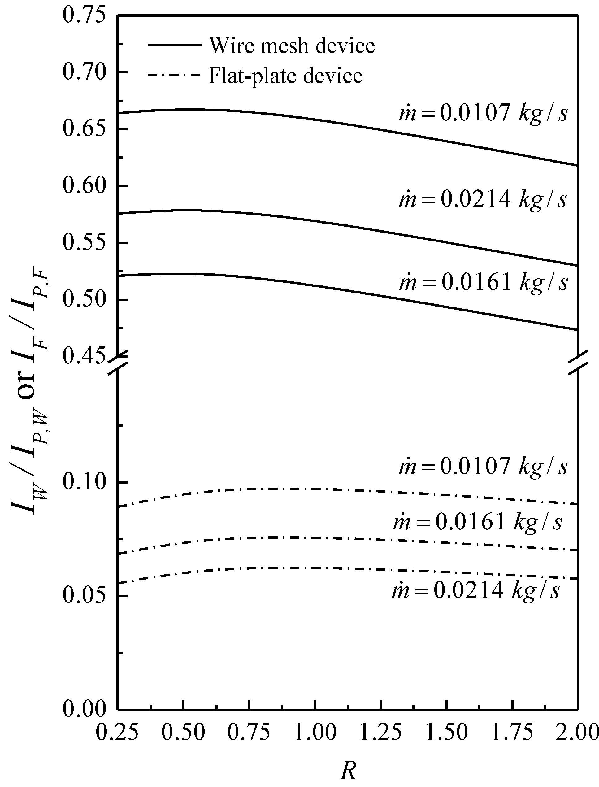
| IF | percentage of collector efficiency improvement in flat-plate air heater, defined in Equations (18) |
| IP,i | percentage of power consumption increment, defined in Equations (26) and (27) |
| IW | percentage of collector efficiency improvement in wire mesh air heater, defined in Equations (19) |
| k | thermal conductivity of the stainless steel plate (W/(m·K)) |
| ki | coefficients defined in Equations (A18) and (A19) |
| ks | thermal conductivity of insulator (W/(m·K)) |
| L | channel length (m) |
| l | the maximum length of the mesh (m) |
| ls | thickness of insulator (m) |
lower subchannel friction loss of double-pass device (J/kg) | |
upper subchannel friction loss of double-pass device (J/kg) | |
friction loss of downward-type single-pass device (J/kg) | |
| Ma | parameter defined in Equation (A8) (J/(s·m2·K)) |
| Mb | parameter defined in Equation (A7) (J/(s·m2·K)) |
total air mass flow rate (kg/s) | |
| Nexp | the number of the experimental measurements |
| Nu,i | Nusselt number |
| n | number of screens in a matrix |
| P | porosity of mesh |
| Pt | pitch of wire mesh (m) |
| Qu | useful energy gained by air (W) |
| rh | hydraulic radius (m) |
| R | recycle ratio, reverse air mass flow rate divided by input air mass flow rate |
| Re0 | Reynolds number, |
| Rea | Reynolds number, |
| Reb | Reynolds number, |
| s | shortway of mesh (m) |
| Ta(ξ) | axial fluid temperature distribution in the lower subchannel (K) |
| Tb(ξ) | axial fluid temperature distribution in the upper subchannel (K) |
the mixing temperature of the subchannel a at x = 0 (K) | |
| Ta,L | the temperature of the lower subchannel at x = L (K) |
| Ta,m | the mean temperature of the lower subchannel (K) |
| Tb,0 | the temperature of the upper subchannel b at x = 0 (K) |
| Tb,L | the temperature of the upper subchannel b at x = L (K) |
| Tb,m | the mean temperature of the upper subchannel (K) |
| Tb,o | the temperature of the upper subchannel at outlet (K) |
| Tin | inlet air temperature (K) |
| Tp | temperature of absorbing plate (K) |
| Tp,m | mean temperature of absorbing plate (K) |
| Ts | ambient temperature (K) |
| UB | loss coefficient from the bottom of solar air heater to the ambient environment (W/(m2·K)) |
| UE | loss coefficient from the edge of solar air heater to theambient environment (W/(m2·K)) |
| UL | overall loss coefficient (W/(m2·K)) |
| UT | loss coefficient from the top of solar air heater to the ambient environment (W/(m2·K)) |
| V | wind velocity (m/s) |
| W | channel width (m) |
| Yi | coefficient defined in Equations (A16) and (A17) |
Greek Letters
| αP | absorptivity of the absorbing plate |
| ηi | collector efficiency for the flat-plate a and wire mesh packed |
| ηexp,i | experimental data of collector efficiency |
| ηtheo,i | theoretical prediction of collector efficiency |
| ηW | collector efficiency of wire mesh solar air heater |
| τg | transmittance of glass cover |
| εg | emissivity of glass cover |
| εR | emissivity of bottom plate |
| εP | emissivity of absorbing plate |
| ρ | air density (kg/m3) |
| μ | air viscosity (kg/(s·m)) |
| σ | Stefan-Boltzmann constant (= 5.682 × 10⁻⁸) (W/(m2·K4)) |
| ξ | dimensionless channel length |
Acknowledgments
Author Contributions
Appendix
Conflicts of Interest
References
- Chen, X.; Yang, H.; Lu, L.; Wang, J.; Liu, W. Experimental studies on a ground coupled heat pump with solar thermal collectors for space heating. Energy 2011, 36, 5292–5300. [Google Scholar] [CrossRef]
- Sharma, V.K.; Colangelo, A.; Spagna, G. Experimental performance of an indirect type solar fruit and vegetable dryer. Energy Convers. Manag. 1993, 34, 293–308. [Google Scholar] [CrossRef]
- Sreekumar, A. Techno-economic analysis of a roof-integrated solar air heating system for drying fruit and vegetables. Energy Convers. Manag. 2010, 51, 2230–2238. [Google Scholar] [CrossRef]
- Bari, E.; Noel, J.Y.; Comini, G.; Cortella, G. Air-cooled condensing systems for home and industrial appliances. Appl. Therm. Eng. 2005, 25, 1446–1458. [Google Scholar] [CrossRef]
- Chen, Z.; Gu, M.; Peng, D.; Peng, C.; Wu, Z. A Numerical study on heat transfer of high efficient solar flat-plate collectors with energy storage. Int. J. Green Energy 2010, 7, 326–336. [Google Scholar] [CrossRef]
- Seluck, M.K. Solar Air Heaters and Their Applications; Sayigh, A.A.M., Ed.; Academic Press: New York, NY, USA, 1977. [Google Scholar]
- Kreith, F.; Kreider, J.F. Principles of Solar Engineering; McGraw-Hill: New York, NY, USA, 1978. [Google Scholar]
- Tan, H.M.; Charters, W.W.S. Experimental investigation of forced-convective heat transfer for fully-developed turbulent flow in a rectangular duct with asymmetric heating. Sol. Energy 1970, 13, 121–125. [Google Scholar] [CrossRef]
- Yeh, H.M. Theory of baffled solar air heaters. Energy 1992, 17, 697–702. [Google Scholar] [CrossRef]
- Duffie, J.A.; Beckman, W.A. Solar Engineering of Thermal Processes, 3rd ed.; Wiley: New York, NY, USA, 2006. [Google Scholar]
- Ramadan, M.R.I.; EL-Sebaii, A.A.; Aboul-Enein, S.; El-Bialy, E. Thermal performance of a packed bed double-pass solar air heater. Energy 2007, 32, 1524–1535. [Google Scholar] [CrossRef]
- Sopian, K.; Alghoul, M.A.; Alfegi, E.M.; Sulaiman, M.Y.; Musa, E.A. Evaluation of thermal efficiency of double-pass solar collector with porous—Nonporous media. Renew. Energy 2009, 34, 640–645. [Google Scholar] [CrossRef]
- Dhiman, N.K.; Tiwari, G.N. Performance of a two channel suspended flat plate solar air heater. Energy Convers. Manag. 1984, 24, 269–275. [Google Scholar] [CrossRef]
- Naphon, P. On the performance and entropy generation of the double-pass solar air heater with longitudinal fins. Renew. Energy 2005, 30, 1345–1357. [Google Scholar] [CrossRef]
- Ho, C.D.; Yeh, H.M.; Wang, R.C. Heat-transfer enhancement in double-pass flat-plate solar air heaters with recycle. Energy 2005, 30, 2796–2817. [Google Scholar]
- Chiou, J.P.; El-Wakil, M.M.; Duffie, J.A. A slit-and-expanded aluminum-foil matrix solar collector. Sol. Energy 1965, 9, 73–80. [Google Scholar] [CrossRef]
- Choudhury, C.; Garg, H.P. Performance of air-heating collectors with packed airflow passage. Sol. Energy 1993, 50, 205–221. [Google Scholar] [CrossRef]
- Mittal, M.K.; Varshney, L. Optimal thermohydraulic performance of a wire mesh packed solar air heater. Sol. Energy 2006, 80, 1112–1120. [Google Scholar] [CrossRef]
- Öztürk, H.H.; Demirel, Y. Exergy-based performance analysis of packed-bed solar air heaters. Int. J. Energy Res. 2004, 28, 423–432. [Google Scholar] [CrossRef]
- Kolb, A.; Winter, E.R.F.; Viskanta, R. Experimental studies on a solar air collector with metal matrix absorber. Sol. Energy 1999, 65, 91–98. [Google Scholar] [CrossRef]
- El-Sebaii, A.A.; Aboul-Enein, S.; Ramadan, M.E.I.; Shalaby, S.M.; Moharram, B.M. Investigation of thermal performance of double-pass flat and v-corrugated plate solar air heaters. Energy 2011, 36, 1076–1086. [Google Scholar] [CrossRef]
- Marquart, R.; Blenke, H. Circulation of moderately to highly viscous Newtonian and non-Newtonian liquids in propeller-pumped circulating loop reactors. Int. Chem. Eng. 1980, 20, 368–378. [Google Scholar]
- Dussap, G.; Gros, J.B. Energy consumption and interfacial mass transfer area in an air-lift fermentor. Chem. Eng. J. 1982, 25, 151–162. [Google Scholar] [CrossRef]
- Jones, A.G. Liquid circulation in a drift-tube bubble column. Chem. Eng. Sci. 1985, 40, 449–462. [Google Scholar] [CrossRef]
- Ho, C.D.; Yeh, H.M.; Guo, J.J. An analytical study on the enrichment of heavy water in the continuous thermal diffusion column with external refluxes. Sep. Sci. Technol. 2002, 37, 3129–3153. [Google Scholar] [CrossRef]
- Ho, C.D.; Lin, C.S.; Chuang, Y.C.; Chao, C.C. Performance improvement of wire mesh packed double-pass solar air heaters with external recycle. Renew. Energy 2013, 57, 479–489. [Google Scholar] [CrossRef]
- Varshney, L.; Saini, J.S. Heat transfer and flow friction factor correlations for rectangular solar air heater duct packed with wire mesh screen matrices. Sol. Energy 1998, 62, 255–262. [Google Scholar] [CrossRef]
- Chang, W.S. Porosity and effective thermal conductivity of wire screens. J. Heat Transf. 1990, 112, 5–9. [Google Scholar] [CrossRef]
- Kays, W.M. Convective Heat and Mass Transfer; McGraw-Hill: New York, NY, USA, 1996. [Google Scholar]
- Heaton, H.S.; Reynolds, W.C.; Kays, W.M. Heat transfer in annular passages. Simultaneous development of velocity and temperature fields in laminar flow. Int. J. Heat Mass Transf. 1964, 7, 763–781. [Google Scholar] [CrossRef]
- Saini, R.P.; Saini, J.S. Heat transfer and friction factor correlation for artificially roughened ducts with expanded metal mesh as roughness element. Int. J. Heat Mass Transf. 1997, 40, 973–986. [Google Scholar] [CrossRef]
- Klein, S.A. Calculation of flat-plate loss coefficients. Sol. Energy 1975, 17, 79–80. [Google Scholar] [CrossRef]
- Hottel, H.C.; Woetz, B.B. The performance of flat-plate solar heat collectors. Trans. ASME 1942, 64, 91–104. [Google Scholar]
- McAdams, W.H. Heat Transmission, 3rd ed.; McGraw-Hill: New York, NY, USA, 1954. [Google Scholar]
- Prasad, S.B.; Saini, J.S.; Singh, K.M. Investigation of heat transfer and friction characteristics of packed bed solar air heater using wire mesh as packing material. Sol. Energy 2009, 83, 773–783. [Google Scholar] [CrossRef]
- Bird, R.B.; Stewart, W.E.; Lightfoot, E.N. Transport Phenomena, 2nd ed.; Wiley: New York, NY, USA, 2007. [Google Scholar]
- Mohseni-Languri, E.; Taherian, H.; Masoodi, R.; Reisel, J.R. An energy and exergy study of a solar thermal air collector. Therm. Sci. 2009, 13, 205–216. [Google Scholar] [CrossRef]
- Mohseni-Languri, E.; Taherian, H.; Hooman, K.; Reisel, J.R. Enhanced double-pass solar air heater with and without porous medium. Int. J. Green Energy 2011, 8, 643–654. [Google Scholar] [CrossRef]
© 2014 by the authors; licensee MDPI, Basel, Switzerland. This article is an open access article distributed under the terms and conditions of the Creative Commons Attribution license (http://creativecommons.org/licenses/by/4.0/).
Share and Cite
Ho, C.-D.; Lin, C.-S.; Yang, T.-J.; Chao, C.-C. Recycle Effect on Device Performance of Wire Mesh Packed Double-Pass Solar Air Heaters. Energies 2014, 7, 7568-7585. https://doi.org/10.3390/en7117568
Ho C-D, Lin C-S, Yang T-J, Chao C-C. Recycle Effect on Device Performance of Wire Mesh Packed Double-Pass Solar Air Heaters. Energies. 2014; 7(11):7568-7585. https://doi.org/10.3390/en7117568
Chicago/Turabian StyleHo, Chii-Dong, Chun-Sheng Lin, Tz-Jin Yang, and Chun-Chieh Chao. 2014. "Recycle Effect on Device Performance of Wire Mesh Packed Double-Pass Solar Air Heaters" Energies 7, no. 11: 7568-7585. https://doi.org/10.3390/en7117568