Dynamics and Control of Lateral Tower Vibrations in Offshore Wind Turbines by Means of Active Generator Torque


Abstract
: Lateral tower vibrations of offshore wind turbines are normally lightly damped, and large amplitude vibrations induced by wind and wave loads in this direction may significantly shorten the fatigue life of the tower. This paper proposes the modeling and control of lateral tower vibrations in offshore wind turbines using active generator torque. To implement the active control algorithm, both the mechanical and power electronic aspects have been taken into consideration. A 13-degrees-of-freedom aeroelastic wind turbine model with generator and pitch controllers is derived using the Euler–Lagrangian approach. The model displays important features of wind turbines, such as mixed moving frame and fixed frame-defined degrees-of-freedom, couplings of the tower-blade-drivetrain vibrations, as well as aerodynamic damping present in different modes of motions. The load transfer mechanisms from the drivetrain and the generator to the nacelle are derived, and the interaction between the generator torque and the lateral tower vibration are presented in a generalized manner. A three-dimensional rotational sampled turbulence field is generated and applied to the rotor, and the tower is excited by a first order wave load in the lateral direction. Next, a simple active control algorithm is proposed based on active generator torques with feedback from the measured lateral tower vibrations. A full-scale power converter configuration with a cascaded loop control structure is also introduced to produce the feedback control torque in real time. Numerical simulations have been carried out using data calibrated to the referential 5-MW NREL (National Renewable Energy Laboratory) offshore wind turbine. Cases of drivetrains with a gearbox and direct drive to the generator are considered using the same time series for the wave and turbulence loadings. Results show that by using active generator torque control, lateral tower vibrations can be significantly mitigated for both gear-driven and direct-driven wind turbines, with modest influence on the smoothness of the power output from the generator.1. Introduction
Modern multi-megawatt wind turbines are designed with increasingly larger rotors and higher towers, in order to capture more energy throughout their lifetime and, thereby, reduce the cost of energy. As wind turbines grow in size, the stiffness of the blades and the tower are not increased proportionally, rendering the structure more sensitive to dynamic excitations. Normally, vibrations in the flap-wise direction and tower vibration in the mean wind direction are highly damped due to the strong aerodynamic damping [1]. In contrast, edgewise vibrations and lateral tower vibrations are related with insignificant aerodynamic damping [1,2]. Hence, these modes of vibrations may be prone to large dynamic responses. Most offshore wind turbines are placed at shallow water. Due to refraction, the approaching waves tend to propagate in a direction normal to the level curves of the sea bottom. In turn, this means that the wave load may act in a different direction of the mean wind direction, and significant lateral tower vibrations may be initiated by the wave load in combination with the resultant aerodynamic load from the three blades in the lateral direction.
Some studies have been carried out for the structural control of tower vibrations, most of which focus on passive structural control techniques. Theoretical investigations have been performed on the effectiveness of a tuned mass damper (TMD) [3] and tuned liquid column damper (TLCD) [4] for mitigating along-wind vibrations of wind turbine towers, ignoring the aerodynamic properties of the blades. To yield more realistic results, an advanced modeling tool has been developed and incorporated into the aeroelastic code, FAST (Fatigue, Aerodynamics, Structures and Turbulence), allowing the investigation of passive TMDs in vibration control of offshore wind turbine systems [5]. Recently, a series of shaking table tests have been carried out to evaluate the effect of the ball vibration absorber (BVA) on the vibration mitigation of a reduced scale wind turbine model, which proves the effectiveness of the passive damping device [6]. However, the focus of this study is still on along-wind vibrations without considering the aerodynamic damping. Active structural control of floating wind turbines is investigated by Lackner and Rotea [7]. Simulation results in FAST show that active control is a more effective way of reducing structural loads than the passive control method, at the expense of active power and larger TMD strokes.
For modern variable speed wind turbines, advanced pitch control and generator torque control techniques for the mitigation of structural loads are being increasingly investigated. In a basic variable speed wind turbine control system, torque control is used in below-rated wind speeds to obtain maximum energy output. Above the rated speed, a pitch controller is utilized to regulate the rotor speed to the desired value, and the generator torque is held constant (nominal torque) [8]. Additional pitch control loops as feedback from measured nacelle fore-aft acceleration are usually used to damp fore-aft tower vibrations [9], although vibration in this direction is already highly damped due to the aerodynamic damping. Generator torque control is widely used to provide damping into the drivetrain torsional vibrations [9–11]. Instead of demanding a constant generator torque above the rated one, an additive torque as feedback from the measured generator speed is added to the torque demand, which is effective at damping vibrations of the resonant mode of the drivetrain.
The idea of providing active damping to lateral tower vibration using generator torque was first proposed by Van der Hooft et al. [12] and was further investigated by de Corcuera et al. [13] and Fleming et al. [14]. Essentially, the generator torque affects the lateral tower vibration through the reaction on the generator stator, which is rigidly fixed to the nacelle. By means of modern power electronics, the generator torque can be prescribed to a certain value with a delay below 10−2 s [15]. By using this property, feedback control of the lateral tower vibrations can be performed. Van der Hooft et al. [12] simplified the tower by a single-degree-of-freedom (SDOF) representing the lateral translational motion, and the tower top rotation was neglected. Since the generator torque is affecting the lateral tower motion via the tower top rotation, this SDOF tower model does not adequately account for the transfer of the generator torque. De Corcuera et al. [13] demonstrated a strategy to design a multi-variable controller based on the H∞ norm reduction for reducing both the drivetrain torsional vibration and the tower side-to-side vibration, with simulations carried out in the GH Bladed software. This study focuses on the controller design procedure. However, the torque transfer mechanism from the generator to the tower vibration and the effect of the generator torque on other components of the wind turbine are not demonstrated. Fleming et al. [14] presented the field-testing results of the effect of active generator control on the drivetrain and lateral tower vibrations in a 600-kW wind turbine. A multi-SISO (single-input-single-output) controller is compared with the H∞ controller, and a similar effect for damping the lateral tower vibration was obtained. Again, the effect of the generator torque on other components of the wind turbine, such as the blades, was ignored. Actually, the edgewise vibrations of the blades are coupled to the lateral tower vibration, as well as to the torsional drivetrain vibration through the collective mode. Since very low, even negative, aerodynamic damping takes place in edgewise vibration, it is important to investigate the effect of the active generator torque on this mode of vibration. Moreover, as the basis of implementing active generator control, the load transfer mechanisms from the drivetrain and the generator to the nacelle, as well as the interaction between the generator torque with the lateral tower vibration are not clearly demonstrated in the above-mentioned studies. Further, all of the previous studies focus on the gear-driven wind turbines. With offshore wind turbines becoming larger and being moved out further at sea, there is huge application potential of direct-driven systems, where the turbine rotor is coupled directly to the electrical generator without the gearbox. The generators operate at the same rotational speed as the turbine’s rotor and must therefore be much bigger in size. However, by using permanent magnets in the generators’ rotor and eliminating the gearbox, the weight of the nacelle can be significantly decreased compared to that of the gear-driven system, which, in turn, reduces the shipping and installation costs for offshore wind farms. Further, since the gearbox causes the greatest downtime resulting in lost revenue, the use of a direct-driven system definitely avoids the cost of overhauling, removing and reinstalling the gearbox, thus reducing operating costs over the long term and making electricity from wind farms more competitive. This is especially important for offshore wind farms, because doing maintenance at sea is a lot more complex and expensive than on the ground. For the direct-driven wind turbines, the electric torque in the generator is much larger comparing with the gear-driven wind turbines, making it possible to damp the lateral tower vibration more effectively.
This paper presents a comprehensive investigation into the modeling and control of lateral tower vibrations in offshore wind turbines using active generator torque, taking into consideration the consequences of the control on the edgewise blade vibrations and the quality of the produced power. The load transfer mechanisms from the generator to the tower are derived in a generalized form for gear-driven wind turbines with an odd or even number of gear stages, as well as for the direct-driven wind turbines. The active generator control algorithm is investigated based on a 13-degrees-of-freedom (13-DOF) wind turbine model developed by the authors, which has been calibrated to the referential 5-MW NREL (National Renewable Energy Laboratory) offshore wind turbine [16]. A three-dimensional (3D) turbulence field is modeled by a low order auto-regressive (AR) model [17]. The dynamic loading from the rotational sampled turbulence and the non-linear aeroelasticity is assumed to be quasi-static, i.e., the changes of aerodynamic forces due to changes of the angle of attack are felt without time delay. The wave load is modeled by the Morison formula [18] in combination with the first order wave theory and applied to the tower in the lateral direction. A generator model is proposed with a complete solution to provide the feedback control torque. Cases of gear-driven and direct-driven wind turbines are both investigated. Simulation results show that lateral tower vibration can be significantly suppressed, and the edgewise vibrations are also slightly mitigated by the active generator control, while only modest influence on the smoothness of the power output are brought about by the additive generator torque.
2. Wind Turbine Model
In this section, a 13-DOF aeroelastic wind turbine model is presented with coupled edgewise, lateral tower and torsional drivetrain vibrations. The torque transfer mechanism between the drivetrain and the tower are derived in a generalized manner, which forms the basis for active control of tower vibrations using the generator torque.
2.1. General Description
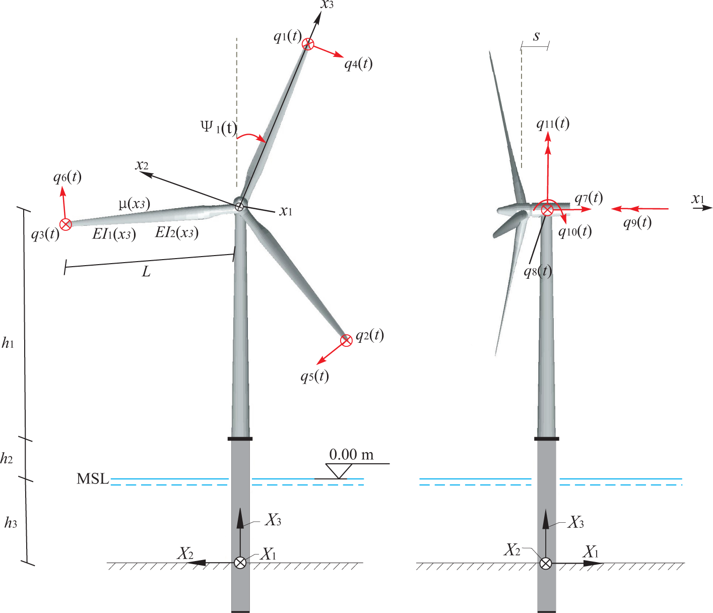
Despite its simplicity, the 13-DOF aeroelastic model takes into account several important characteristics of a wind turbine, including time-dependent system matrices, coupling of the tower-blades-drivetrain vibration, as well as non-linear aeroelasticity. A schematic representation of the wind turbine model is shown in Figure 1. The motion of structural components is described either in a fixed, global frame of reference (X1, X2, X3) or in moving frames of reference (x1, x2, x3), attached to each blade with the origin at the center of the hub. Neglecting the tilt of the rotor, the X1 and x1 axis are unidirectional to the mean wind velocity. The (X2, X3) and (x2, x3) coordinate planes are placed in the rotor plane. The X3 axis is vertical, and the x3 axis is placed along the blade axis oriented from the hub towards the blade tip. The position of the moving frame attached to blade j is specified by the azimuthal angle Ψj(t), which is considered positive when rotating clockwise seen from an upwind position.
The blades are modeled as Bernoulli–Euler beams with the bending stiffness EI1(x3) in the flap-wise direction and EI2(x3) in the edgewise direction. The mass per unit length is μ(x3). Each blade is related with two degrees of freedom (DOFs). q1(t), q2(t), q3(t) denote the flapwise tip displacement in the positive x1 direction. q4(t), q5(t), q6(t) denote the edgewise tip displacement in the negative x2 direction. The length of each blade is denoted L. The tower motion is defined by five DOFs q7(t),…, q11(t). q7(t) and q8(t) signify the displacements of the tower at the height of the hub in the global X1 and X2 directions. q9(t) specifies the elastic rotation of the top of the tower in the negative X1 direction, and q10(t) and q11(t) indicate the corresponding rotations in the positive X2 and X3 directions. The height of the tower from the base to the nacelle is denoted h1, and the tower base begins at an elevation of h2 above mean sea level (MSL), with a monopile extending from the tower base to the mud line. The water depth from the mud line to the MSL is denoted h3, and the horizontal distance from the center of the tower top to the origin of the moving coordinate systems is denoted s (Figure 1).
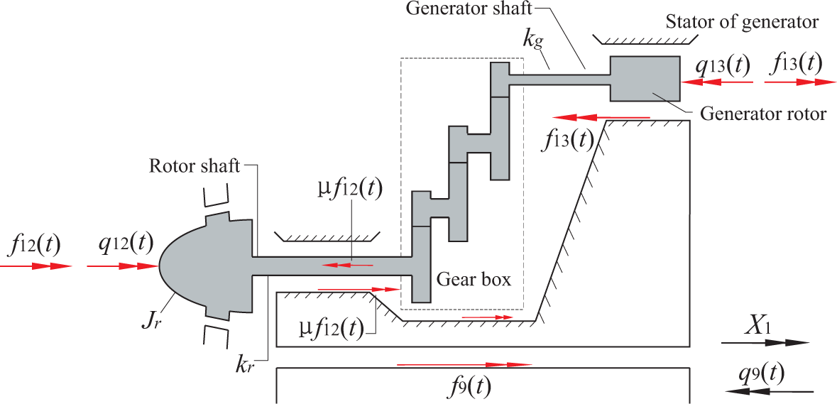
The drivetrain is modeled by the DOFs q12(t) and q13(t) (Figure 2). The sign definition shown in Figure 2 applies to a gearbox with an odd number of stages. q12(t) and q13(t) indicate the deviations of the rotational angles at the hub and the generator from the nominal rotational angles Ωt and NΩt, respectively, where N is the gear ratio. Correspondingly, and are the deviations of the rotational speeds at the hub and the generator from the nominal values. In case of an even number of stages, the sign definitions for q13(t) and f13(t) are considered positive in the opposite direction. Jr and Jg denote the mass moment of inertia of the rotor and the generator; and kr and kg denote the St. Venant torsional stiffness of the rotor shaft and the generator shaft. The azimuthal angle of the blade j (Figure 1) becomes
Further, a full-span rotor-collective pitch controller is included in the model with time delay modeled by a first order filter. The pitch demand is modeled by a PI controller [19] with feedback from and q12(t). A gain-scheduled PI controller is used in this paper, i.e., the controller gains are dependent on the blade-pitch angle [16].
2.2. Coupled Edgewise, Lateral Tower and Torsional Drivetrain Vibrations
The equations of motion of the 13-DOF wind turbine model can be derived from the Euler–Lagrange equation [20]:
Assuming linear structural dynamics and substituting the expressions for kinetic and potential energies into Equation (1), the equations of motion of the 13-DOF wind turbine model are obtained of the form:
Next, the DOFs vector q(t) may be partitioned in the following way:
The main focus of the present study is on the dynamic coupling of edgewise, lateral tower and torsional drivetrain motions and the effect of active generator torque on these vibrations. To clearly unfold this coupling, only the sub-system related to DOFs q1(t) is picked out from Equation (2) and is demonstrated in detail. It should be noted that the numerical simulations in the subsequent section will always be based on Equation (2), where all of the 13 DOFs are activated. As a part of Equation (2), the equations of motion related to the above-mentioned sub-system, which show the coupling of edgewise, lateral tower and torsional drivetrain vibrations, are demonstrated by the following matrix differential equations:
Φ(x3) is the undamped eigenmode in the edgewise direction, when the blade is fixed at the hub. Due to the definition of qj+3(t), j = 1, 2, 3, this mode must be normalized to one at the tip, i.e., Φ(L) = 1. is the centrifugal axial force on the blade. m0 is the mass of each blade, and M0 is the mass of the nacelle. is the modal damping coefficient of the edgewise vibration, calculated from the given damping ratio ζ2.
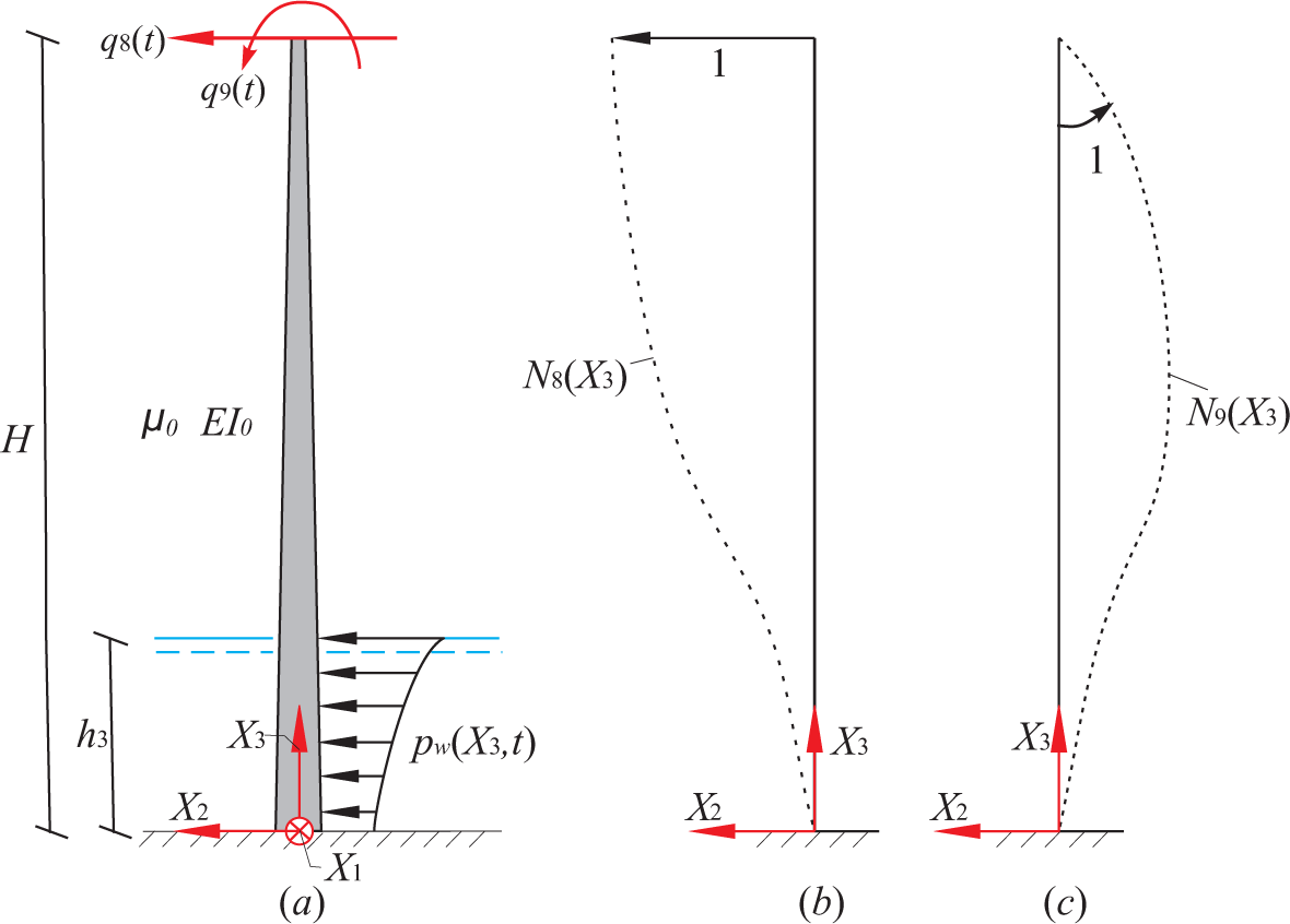
As shown in Figure 3, the lateral tower vibration is modeled by two DOFs, q8(t) and q9(t), with cubic shape functions N8(X3) and N9(X3), respectively. The consistent mass and stiffness terms for q8(t) and q9(t) are calculated from the tower itself without considering the nacelle and the rotor, as given by the following equation:
From Equation (6), it is noted that the edgewise vibrations are coupled to the lateral tower vibration through the mass matrix, damping matrix and stiffness matrix and coupled to the drivetrain torsional vibration through the mass matrix alone. Actually, only the collective mode of the edgewise vibration is coupled with the torsional vibration of the drivetrain.
2.3. Torque Transfer Mechanism between the Drivetrain and the Tower
In Equation (5), the external dynamic load vector work conjugated to q1(t) is expressed as:
Using D’Alembert’s principle, the net torque on the drivetrain in the global X1 direction becomes , where the plus sign applies for a gearbox with an odd number of gear stages (as shown in Figure 2) and the minus sign for an even number of stages. The torque is transferred to the nacelle in the positive X1 direction via the bearings of the shaft and the gearbox. On the nacelle, the transferred torque is added to the reaction of the friction torque μf12(t) (always in the positive X1 direction) and the generator torque on the stator f13(t), which is acting in the negative X1 direction for an odd number of stages or acting in the positive X1 direction for an even number of stages. Hence, the resultant torque on the bottom of the nacelle becomes (plus sign for an odd number of gear stages). With q9(t) defined as positive when acting in the negative X1 direction, the torque work-conjugated to q9(t) resulting from the nacelle becomes (minus sign for an odd number of gear stages). Then, together with the contribution from the wave load, the total load work-conjugated to q9(t) becomes:
The control of the lateral tower vibration is actually applied via the torque f9(t) conjugated to q9(t). For this reason, the relation between f9(t) and f13(t) is analyzed. The equation of motion of the drivetrain reads from Equations (5) and (10):
The acceleration terms in Equation (11) can be eliminated by means of the equation of motion of the drivetrain, resulting in the equivalent expression for f9(t):
Especially for direct-driven wind turbines, where N = 1, we get from the second equation in Equation (14) that:
It is seen from the last part of the two sub-equations in Equation (14) that for gear-driven wind turbines, there are extra coupling terms between the degree of freedom q9(t) and the two DOFs of the drivetrain, which can be transferred and added to the stiffness matrix in Equation (6). Based on the relationship between f9(t) and f13(t) in Equations (14) and (15), the lateral tower vibrations can be controlled by specifying the format of the generator torque f13(t), as will be shown in the subsequent section.
2.4. Aerodynamic and Wave Loads
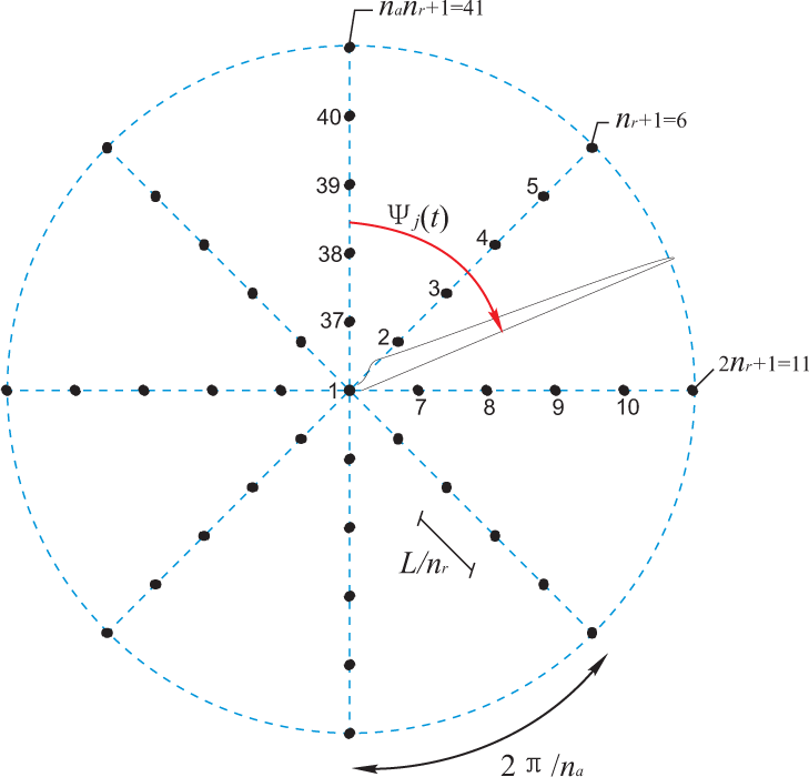
In agreement with [22], the turbulence modeling is based on Taylor’s hypothesis of frozen turbulence, corresponding to a frozen turbulence field that is convected into the rotor in the global X1 direction with a mean velocity V0, which provides the relation between spatial coordinates and time. The frozen field is assumed to be a zero mean homogeneous and isotropic stochastic field, with a spatial covariance structure given by [23]. Calibrated from the theoretical covariance structure, the first order AR model as proposed by [17] performs a first-order filtering of the white noise input, resulting in continuous, non-differentiable sample curves of the turbulence field at the rotor plane in the fixed frame of reference. As shown in Figure 4, the fixed frame components of the convected turbulence are generated at nn = na ·nr +1 nodal points at the discrete instants of time t = 0, Δt, 2Δt,s…, where na is the number of radial lines in the mesh from the center Node 1 and nr is the number of equidistantly placed nodes along a given radial line. Next, the fixed frame components of the rotational sampled turbulence vector on each blade with the azimuthal angle Ψj are obtained by linear interpolation of the turbulence of the adjacent radial lines according to the position of the blade at each time step. Finally, the moving frame components of the rotational sampled turbulence are obtained by the following coordinate transformation:
The blade element momentum (BEM) method with Prandtl’s tip loss factor and Glauert correction is adopted to calculate aerodynamic forces along the blade [24]. Non-linear aeroelasticity is considered by including the local deformation velocities of the blade into the calculation of the flow angle and the angle of attack. As a result, high aerodynamic damping is introduced in the blade flap-wise and the fore-aft tower vibrations, but relatively low aerodynamic damping in the blade edgewise and the lateral tower vibrations.
Sea surface elevation is modeled as a zero mean, stationary Gaussian process defined by the single-sided version of the JONSWAP (Joint North Sea Wave Project) spectrum [25], which is determined by the significant wave height Hs and the peak period Tp. Assuming first order wave theory, the realization of the stationary wave surface elevation process can be obtained by the following random phase model:
Following the linear wave theory, the horizontal velocity v(X3, t) and acceleration of the water particle at the position X2 = 0 can be written as:
The distributed wave force acting at the position X3 of the tower can be calculated by the Morison Equation [18]:
3. Active Generator Control
A simple active control algorithm is proposed based on active generator torque with feedback from the measured lateral tower vibrations. Closed-loop equations are obtained from the active control. A full-scale power converter configuration with a cascaded loop control structure is also introduced to produce the feedback torque in real time.
3.1. Closed-Loop Equations from Active Control
Only the above rated region (Region 3 according to [16]) is considered where the mean wind speed is higher than the rated value, and the wind turbine produces nominal power with the functioning of the collective pitch controller. In the basic control system for Region 3, the collective pitch controller is activated to regulate the rotor speed to the nominal value, while the generator torque is held constant [9]. Modern power electronics makes it possible to specify the generator torque within certain limits almost instantly (time delay below 10−2 s). Then, the generator torque f13(t) can be used as an actuator in the active vibration control of the structure. Sometimes, a torsional damping term as feedback control is included in the generator torque to damp the resonant mode of the drivetrain [10]. Since the focus is to investigate the effectiveness of active generator control of lateral tower vibrations and the influence of the controller on the power output, as well as on the responses of other components, the torsional damping term is not taken into account in the present study. The generator controller with feedback from lateral tower vibrations is proposed as:
Then, the generated power becomes:
The torque f9(t) work-conjugated to q9(t) for wind turbines with an active generator controller follows from Equations (14) and (20):
Substituting Equations (20) and (23) into the load vector (Equation (10)) at the right-hand side of Equation (5), the equation of motion of the system with active generator controller is given by:
The system matrices M1(t), C1(t), K1(t) and the load vector fe,1(t) are unchanged, except that an extra damping matrix Ca(t) is introduced by the active generator controller. Therefore by making use of the extra damping matrix, it is possible to mitigate lateral tower vibrations, as will be shown in the following simulation results. The upper sign in Equation (25) refers to the gearbox with an odd number of stages, while the lower sign corresponds to the case with an even number of gear stages, which also applies to the direct-driven wind turbines (the number of stages is zero).
3.2. Power Electronic Solution for Torque Control
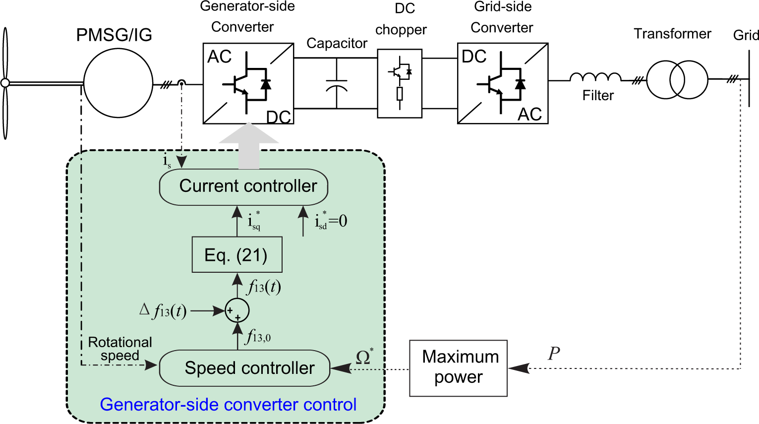
In order to realize the objective of active control of lateral tower vibration using the generator torque, a generator model is introduced. As seen in Figure 5, a full-scale power converter configuration equipped with a permanent magnet synchronous generator (PMSG) or an induction generator (IG) is considered [15]. Normally, a PMSG-based wind turbine may become a direct-driven system, which avoids the fatigue-prone gearbox. The principle of the full-scale power converter is the same for both IG and PMSG. The generator stator winding is connected to the grid through a full-scale back-to-back power converter, which performs the reactive power compensation and a smooth grid connection. Due to different positions, the back-to-back power converter is named as the generator-side converter and the grid-side converter, respectively. The grid-side converter is used to keep the DC-link voltage VDC fixed and to meet the reactive power demand according to the grid codes [26].
The active generator control scheme for lateral tower vibration is carried out via the generator-side converter. With the aid of the stator field oriented control (as shown in Figure 5), a cascaded loop control structure is realized by two controllers: outer speed loop and inner current loop. According to the maximum power tracking point, the rotor speed demand is calculated by the measured power fed into grid. Above the rated region, the speed control loop provides a torque demand of f13,0. Along with additive generator torque demand , the total torque demand is given in the same form as Equation (20). The electromagnetic torque Te of the generator can be expressed as [27]:
From the power electronic point of view, direct driven and gear-driven wind turbines are basically dependent on which kind of generator the manufacturer prefers to use. If the synchronous generator is selected, due to the relatively low speed of the generator rotor, the wind turbine system could have less stages of the gearbox or even becomes direct-driven if the poles of the generator are high enough (e.g., permanent-magnet synchronous generator). On the other hand, if the induction generator is chosen, the gearbox must be employed because of its high rotor speed range, which cannot match the speed of the wind turbine rotor directly.
4. Results and Discussion
Numerical simulations are carried out on the calibrated 13-DOF model subjected to the wave and wind loads. In all simulations, the same turbulent wind field and wave loads have been used, with the mean wind velocity V0 = 15 m/s, the turbulence intensity I = 10%, the significant wave height Hs = 2 m and the time interval Δt = 0.02 s. The worst case study scenario is considered, i.e., the wave loads are acting on the tower in the lateral direction perpendicular to the mean wind velocity. Both gear-driven and direct-driven wind turbines are investigated to evaluate the effectiveness of active generator torque on mitigating lateral tower vibrations.
4.1. Model Calibration
The NREL 5-MW referential wind turbine [16] together with the monopile-type support structure documented by [28] are used to calibrate the proposed 13-DOF aeroelastic model. The rotor-nacelle assembly of the NREL 5-MW wind turbine, including the aerodynamic, structural and pitch control system properties, remains the same as in [16]. This wind turbine is mounted atop a monopile foundation at a 20-m water depth, and the tower base begins at an elevation of 10 m above mean sea level (MSL). As for the rotor, each blade has eight different airfoil profiles from hub to tip, the lift and drag coefficients of which are obtained by wind tunnel tests. The related data of the modal shapes, the bending stiffness and the mass per unit length of the blade are also given by [16]. As for the support-structure, the distributed properties of the tower and monopile are given by [28]. Based on these data, we can calculate the parameters of the rotor and the support structure (the geometries, the mass parameters and the stiffness parameters) in the 13-DOF model, as presented in Table 1. Next, to evaluate the validity and feasibility of the proposed 13-DOF model, comparisons of some results obtained from the present model and from the NREL FAST program [16] are carried out. Table 2 shows the results for the natural frequencies of the blade and the tower, as well as the steady-state responses of the blade, the tower and the pitch controller at different mean wind speeds. The steady-state responses of the present model are obtained by running simulations on the 13-DOF system at three given, steady and uniform wind speeds, when the turbulence field is inactivated. The simulation lengths are long enough to ensure that all transient behavior has died out. The FAST results for the blade and the pitch controller are given by [16], and the results for the tower are given by [28]. The agreement between FAST and the 13-DOF model is quite good, which validates the present model.
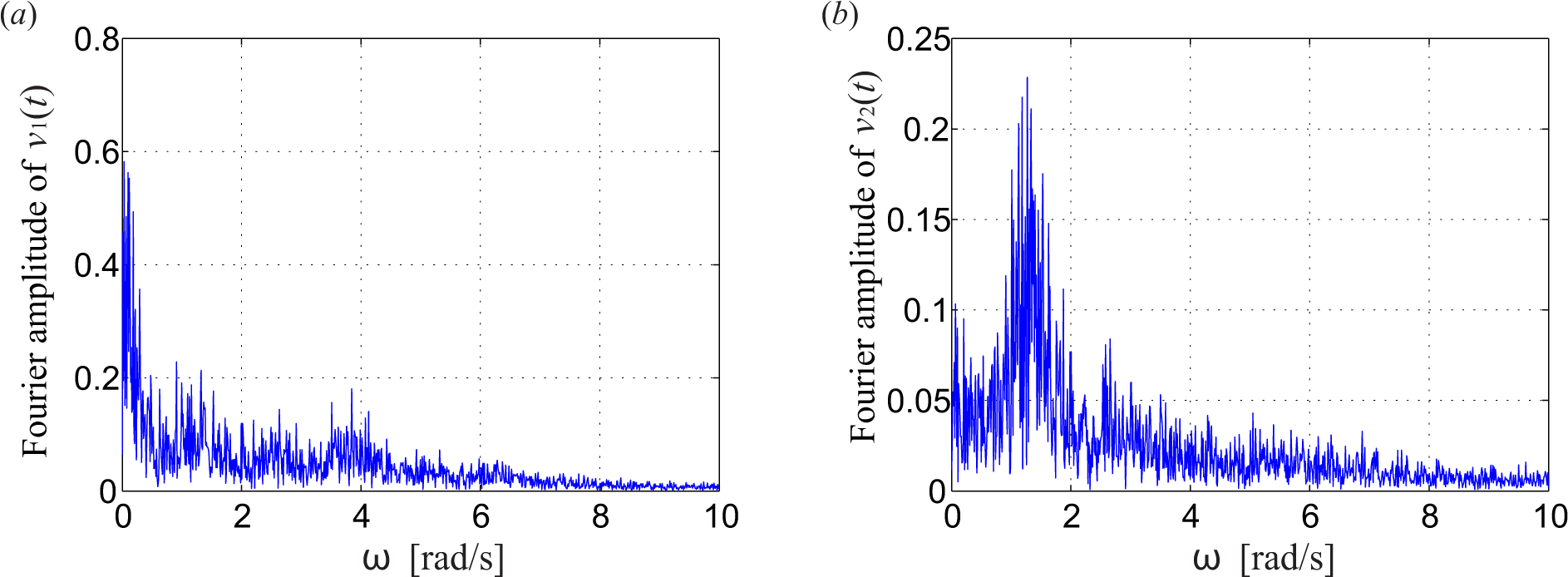
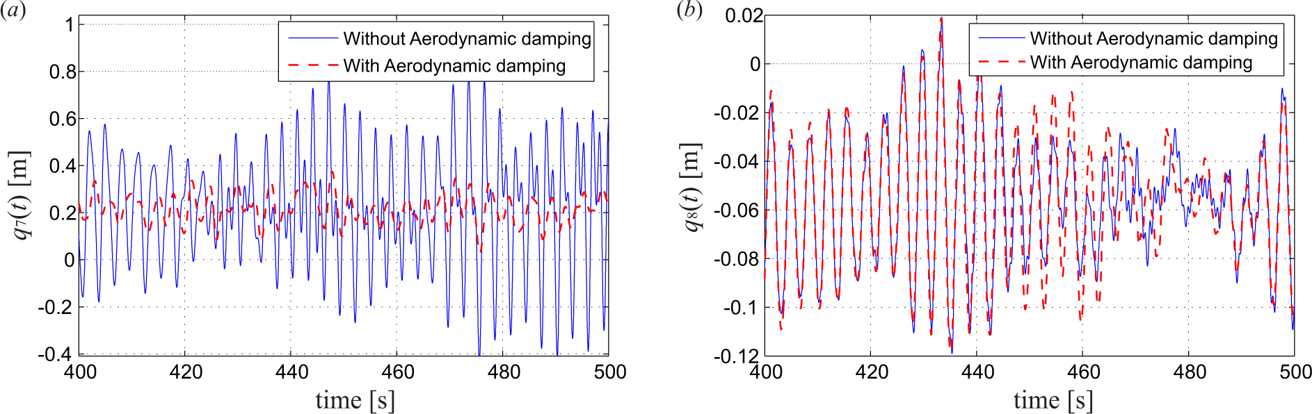
Based on the the model described in Section 2.4, the rotational sampled turbulence field has been generated. Figure 6 shows the Fourier amplitude spectrum obtained by FFT (fast Fourier transformation) of the sample curves of the rotational sampled turbulence, at the middle point of Blade 1. A very clear 1P (1.267 rad/s) frequency component of the turbulence in the x2 direction can be observed in Figure 6b. Less obviously from Figure 6a, the 1P peak can still be observed in the turbulence acting on the blade in the x1 direction. Figure 7 shows the influence of aeroelasticity on tower vibrations in the case of a gear-driven wind turbine with gear ratio N equal to 97. It is seen that the aerodynamic damping almost completely removes the dynamic response of the fore-aft tower vibration q7(t), while the lateral tower vibration q8(t) is almost unaffected by aerodynamic damping, justifying the necessity of implementing active vibration control algorithms in this direction.
Normally, in an irregular sea-state, the mean wind direction and the mean direction of wave propagation are correlated. Hence, the wave loads and the turbulent wind loads on the structure tend to be somewhat unidirectional in most cases. However, we are focusing on the lightly damped lateral tower vibration rather than the along-wind response of the tower with relatively strong aerodynamic damping. Thus, the most conservative load combination is considered in this study, i.e., the wave loads are acting on the tower in the lateral direction perpendicular to the mean wind velocity, in order to fully excite the lateral tower vibration. There is also a clear physical explanation for this load combination. Due to the relatively shallow water, the waves are occasionally refracted tending to propagate orthogonal to the level curves of the sea bottom, meaning that sometimes the direction of wave propagation may take place orthogonal to the mean wind velocity. This load scenario is not expected to take place as often as the unidirectional case. However, considering an offshore wind farm with many wind turbines, there is a high chance that at all times there is a certain amount of wind turbines under such a scenario. The related parameter values used in the aerodynamic and wave loads simulation are also listed in Table 1. In [29], wave measurements were carried out at the German North Sea coast, where the water depth is 29 m. During a severe storm surge on 2 October 2009, the measured significant height was 5.23 m. This data to some extent justify the significant wave height we use (Hs = 2 m) for the 20-m water depth in the simulations. Extensive load cases with different combinations of V0 and Hs (correlated with each other) are not considered in the present study.
4.2. Gear-Driven Wind Turbine
Firstly, simulations are performed considering a gear-driven wind turbine with gear ratio N = 97, which is in accordance with the NREL 5-MW wind turbine. In this case, the rotational speed of the generator is almost N times that of the rotor, and the magnitude of the generator torque is reduced by N times comparing with the aerodynamic torque acting at the rotor. The performance of the wind turbine system is almost the same whether the number of gear stages is odd or even, as long as the gear ratio N is unchanged. Therefore, only the results of the wind turbine with odd-numbered gear stages are illustrated.
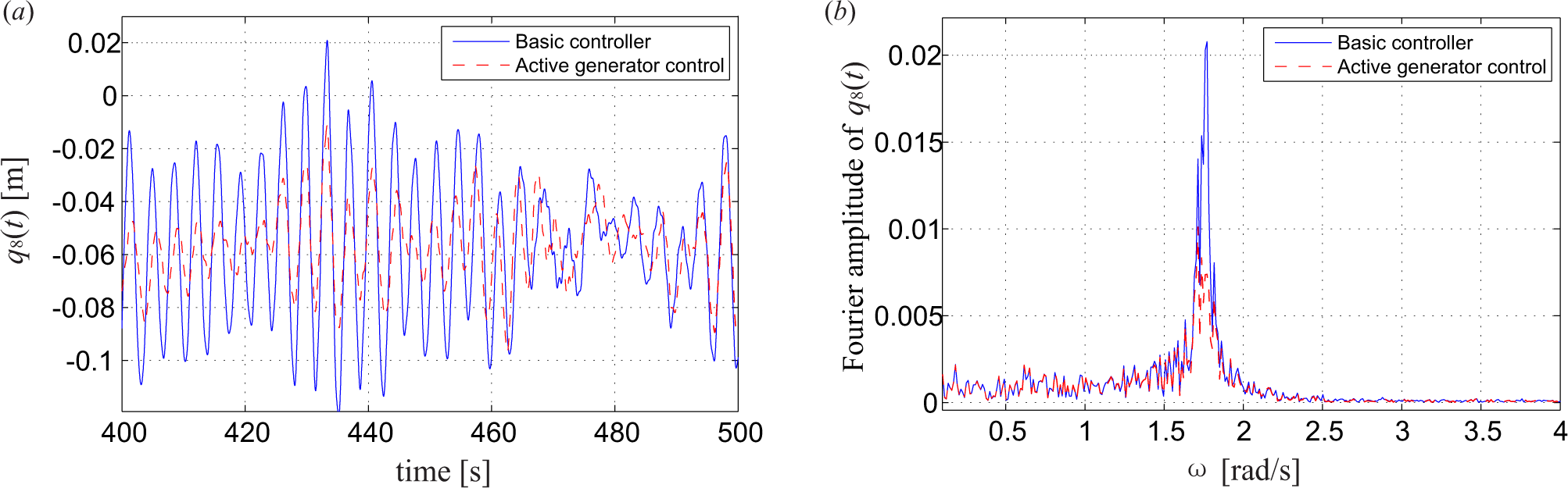
By setting the weighting factor W = 0.5, meaning the same importance is placed on mitigating the tower vibration, and keeping the smoothness of the power output, the gain factor ca is determined as ca = 2.0 × 10⁴ Ns in order to minimize the performance criterion J(ca) in Equation (22). The following figures compare the performance of the wind turbine system with the basic controller and with the active generator controller. Figure 8 shows the lateral tower top displacements q8(t) in both the time and frequency domain, where the blue line denotes the responses without active generator control and the red line with active generator control. There is a reduction of 17.8% in the maximum responses and a reduction of 37.6% in the standard deviations. For both cases, the same static displacement equal to −0.057 m is observed. This is caused by the mean value of the tower torque, which is equal to the negative mean value of the aerodynamic torque at the rotor, i.e., E[f9(t)] = −E[f12(t)], as explained by Equation (11). The FFT of the response q8(t) is presented in Figure 8b. For a system without active generator control, a clear peak corresponding to the tower eigenfrequency (around 1.76 rad/s) is observed without other visible peaks, owing to the fact that very low aerodynamic damping takes place in this mode. This peak is reduced to approximately by the active generator torque due to the introduced damping matrix in Equation (25). Further, it is observed that base moment of the tower in lateral direction is effectively suppressed, as well, with the standard deviation reduced from 5.12 × 10⁶ to 3.32 × 10⁶ Nm and the maximum value reduced from 19.63 × 10⁶ to 15.40 × 10⁶ Nm. The stress at the tower base in the lateral direction is calculated accordingly. There is a reduction of 35.2% (6.80 to 4.41 Mpa) in the standard deviation and a reduction of 21.6% (26.07 to 20.44 Mpa) in the maximum response, which means the fatigue lives of the tower and the foundation are effectively increased by active control.
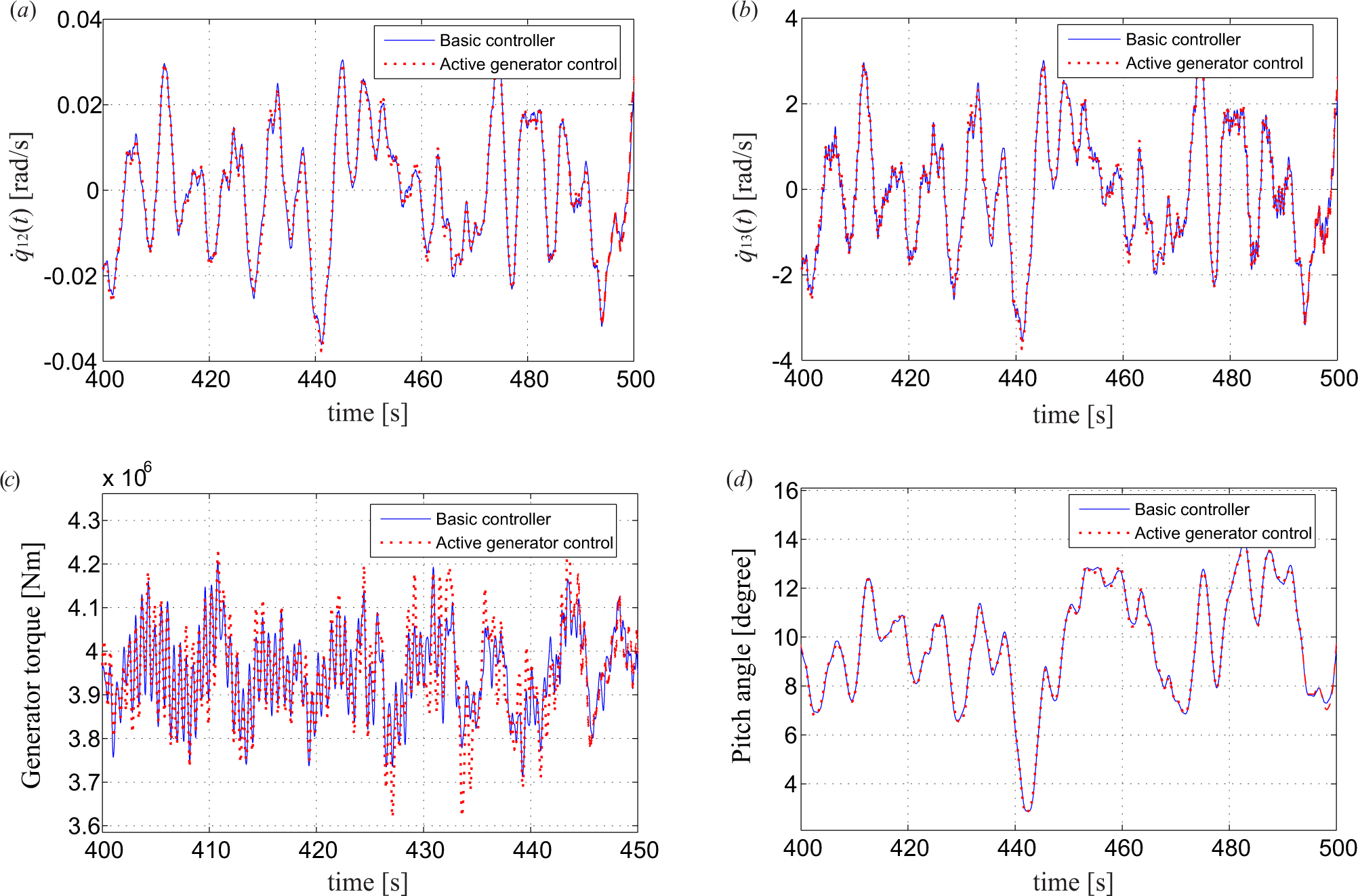
Figure 9 shows the impact of the active control on the performance of the drivetrain shafts, the gearbox and the collective pitch controller. The deviations of the rotational speed at the rotor and at the generator are very slightly affected with the standard deviations increased by 1.0% and 0.92%, respectively, reflecting a very weak coupling between the torsional vibration of the drivetrain with the lateral tower vibration. Based on Equation (13), the dynamic torque acting at the gearbox can also be obtained from q12(t) and q13(t), as shown in Figure 9c. It is seen that the active generator controller introduces a frequency component corresponding to the tower frequency in the gearbox torque, and a little more fluctuated torque is observed with an increase of 12.6% in the standard deviation, which is unfavorable for the fatigue life of the gearbox. By reducing the controller gain ca, the negative effect can be diminished. Further, the performance of the pitch controller is almost unaffected by the active generator control (Figure 9d) with the standard deviation increased by 0.93%. It is observed from Figure 10a,b that the flap-wise tip displacement q1(t) and tower fore-aft top displacement q7(t) are also insignificantly affected with the standard deviations increased by 0.85% and 2.2% after the implementation of active generator control. This is expected, since there is no direct coupling between these two modes of vibration with the generator torque and the lateral tower vibration. The coupling is indirectly via the pitch controller performance, which changes the effective angle of attack and the corresponding aerodynamic loads on the blade sections. Figure 10c shows an interesting result that the edgewise vibration q4(t) is slightly suppressed by the active generator control due to the coupling of edgewise vibration to the lateral tower vibration, as shown in Equation (6). The maximum response and the standard deviation are reduced by 5.5% and 5.0%, respectively. Although the focus is to control the lateral tower vibration through active generator torque, it is favorable to see that the edgewise vibration with very low aerodynamic damping is also suppressed a little, rather than being negatively affected.
The time history of power output from the generator is presented in Figure 11. Since the generated power is related to the lift forces along the blade and, hence, the longitudinal turbulence, the resulting power output also presents periodicity around 1P frequency, similarly with that in Figure 6a. Due to the torque increment , the generated power becomes more fluctuated with an increase of 1.3% in the maximum value and an increase of 33.0% in the standard deviation, relative to the values without active generator control. Since the stiffness and mass of the tower for the offshore wind turbine is very large, it is inevitable that effective control of the tower vibration is at the expense of a little more fluctuated power output, which is unfavorable for the grid side. One possible solution to accommodate this problem is to increase the energy storage in the power converter by increasing the size of the capacitor in Figure 5. To give more clear insight into the tradeoff between the structural vibration and the power output, five different values of weighting factor W are used, i.e., W is chosen to be 0.1, 0.3, 0.5, 0.7 and 0.9. For each W, an optimal value of ca can be obtained through the optimization procedure given by Equation (22). Table 3 presents the optimized ca and the corresponding standard deviations of q8(t) and the power output in different cases. It is shown that as the value of W increases, allowing larger values in the control effort, better structural performance, but worse power quality are achieved. For the extreme case of W = 0.9, the standard deviation of the lateral tower vibration can be reduced by 60%, but the fluctuation of the power output is increased by 121.7%. In this case, one solution may be to turn on the active generator controller merely when large lateral tower vibrations take place.
4.3. Direct-Driven Wind Turbine
Next, simulations of the direct driven wind turbine are carried out. Comparing with the gear-driven wind turbine, the nominal generator torque is increased by N times, while the nominal rotational speed of the generator is reduced by N times. Since the magnitude of the generator is increased significantly, we take the mass moment of inertia of the generator Jg to be N times the original value in the simulation. This is justified by the data of a 3-MW wind turbine [30], where the mass moment of inertia of the generator for the direct driven wind turbine is about 150-times that of the gear-driven one (the total mass is six-times larger and the radius of the stator is five-times larger). The same turbulence field and wave loads as in the previous case are applied to the wind turbine system in order to make meaningful comparisons.
Similarly, by setting W = 0.5, the value of the gain factor ca is determined as 2.0 × 10⁶ in order to minimize the performance criterion J(ca). Figures 12 and 14 show the results corresponding to similar parameters studied in the previous case. Results in Figure 12 show the remarkable capability of the active generator controller in suppressing lateral tower vibrations. The maximum response of q8(t) is reduced from 0.143 to 0.105 m (reduced by 26.6%), and the standard deviation is reduced by 54.0%. Again, a static displacement equal to −0.057 m is always present with or without active control. This value is also unchanged comparing with the gear-driven case, because the mean value of the aerodynamic torque acting at the rotor is unchanged whether it is a gear-driven or direct-driven wind turbine. Further, the stress at the tower base is calculated, with the standard deviation reduced from 6.72 to 3.39 Mpa (49.6%) and the maximum response reduced from 26.12 to 18.90 Mpa (27.6%). The Fourier spectrum of the lateral tower top displacement (Figure 12b) shows that the peak around 1.76 rad/s, corresponding to the tower eigenfrequency, is almost totally eliminated by the active generator controller, comparing with that of the uncontrolled case. The reason for the superior performance is that the nominal generator torque f13,0 is much larger in the direct-driven wind turbine, and thus, the optimized controller gain ca, as well as the additive torque are also increased accordingly.
Figure 13 shows the impact of the active generator controller on the responses of other components of the wind turbine. Similarly, the negative influences on the drivetrain oscillation, the flap-wise vibration, the fore-aft tower vibration and the performance of the pitch controller are negligible. The lightly-damped edgewise vibration in Blade 1 (q4(t)) is again slightly suppressed by the active generator control, due to its coupling to the lateral tower vibration. Similar results have been confirmed for the other two blades. It should be noted that the gearbox is eliminated in the direct-driven system, and the negative impact from the active generator torque on the gearbox as stated in the gear-driven case is no longer a problem for the direct-driven case.
Figure 14 shows the time-history of the power output from the generator. A little negative effect on the smoothness of the power output is observed after the implementation of the active generator control. The maximum value of the power output is increased from 5.41 MW to 5.48 MW (increased by 1.3%), and the standard deviation is increased from 0.108 MW to 0.125 MW (increased by 15.7%), which means less impact on the grid side than that of the gear-driven case. For direct-driven wind turbines, the value of f13,0 is significantly increased, and the relative magnitude between and f13,0 is smaller comparing with that of the gear-driven turbine; thus, the smoothness of the power output is less affected by the active control. Similarly, the tradeoff between the tower vibration and the power output is illustrated in Table 4, showing that as the value of the weighting factor W increases, better structural performance, but worse power quality are obtained. However, acceptable results for the power quality can always be obtained when the tower vibration is significantly reduced.
5. Conclusions
This paper presents a comprehensive investigation into the modeling and control of lateral tower vibrations of offshore wind turbines using active generator torque. A 13-DOF wind turbine model has been developed using a Euler–Lagrangian approach, taking into consideration the quasi-static nonlinear aeroelasticity. The equation of motion was derived, and the coupling of the blade-tower-drivetrain motion, as well as the load transfer mechanisms from the generator to the tower are demonstrated. A simple feedback controller was proposed for lateral tower vibrations through the active generator torque, and a generator model was introduced as the power electronic solution for providing the additive generator torque in real time.
Numerical simulations have been carried out using data calibrated to the referential 5-MW NREL offshore wind turbine. Cases of the gear-driven and the direct-driven wind turbines were both considered to evaluate the effectiveness of the active generator torque for mitigating lateral tower vibrations. The non-linear time-history results demonstrate that for both gear-driven and direct-driven wind turbines, the active generator controller is successfully able to reduce the lateral tower vibration induced by the combined aerodynamic and hydrodynamic loads. The effective control of lateral tower vibration is at the expense of a little more fluctuated power output, and a tradeoff between the vibration aspect and the power electronic aspect should be considered by properly choosing the controller gain. The active generator controller has negligible affects on the drivetrain oscillation, the flap-wise vibration, the fore-aft tower vibration and the performance of the controller. It is also favorable to observe that the lightly-damped edgewise vibration is slightly suppressed by the active generator controller due to its coupling to the lateral tower vibration. The active generator controller shows superior performance for the direct-driven wind turbine, since a better vibration control efficacy can be obtained with less impact on the smoothness of the power output.
In further works, a more sophisticated and realistic consideration of the wind-wave correlation needs to be investigated. The controller will also be developed in more detail, such as to include filters and to design the controller when there is a slight rotor imbalance.
Acknowledgments
The first author gratefully acknowledges the financial support from the Chinese Scholarship Council under the State Scholarship Fund.
Author Contributions
This paper is a result of the collaboration of all co-authors. Zili Zhang and Søren R.K. Nielsen established the wind turbine model and designed the controller. Frede Blaabjerg and Dao Zhou proposed the power electronic solution for the active generator control. Zili Zhang was mainly responsible for numerical simulation, results interpretation and initial writing. All co-authors performed editing and reviewing of the paper.
Conflicts of Interest
The authors declare no conflict of interest.
References
- Hansen, M.H. Aeroelastic instability problems for wind turbines. Wind Energy 2007, 10, 551–577. [Google Scholar]
- Thomsen, K.; Petersen, J.T.; Nim, E.; Oye, S.; Petersen, B. A method for determination of damping for edgewise blade vibrations. Wind Energy 2000, 3, 233–246. [Google Scholar]
- Murtagh, P.J.; Ghosh, A.; Basu, B.; Broderick, B.M. Passive control of wind turbine vibrations including blade/tower interaction and rotationally sampled turbulence. Wind Energy 2008, 11, 305–317. [Google Scholar]
- Colwell, R.; Basu, B. Tuned liquid column dampers in offshore wind turbines for structural control. Eng. Struct. 2009, 31, 358–368. [Google Scholar]
- Lackner, M.A.; Rotea, M.A. Passive structural control of offshore wind turbines. Wind Energy 2011, 14, 373–388. [Google Scholar]
- Zhang, Z.L.; Chen, J.B.; Li, J. Theoretical study and experimental verification of vibration control of offshore wind turbines by a ball vibration absorber. Struct. Infrastruct. Eng. 2014, 10, 1087–1100. [Google Scholar]
- Lackner, M.A.; Rotea, M.A. Structural control of floating wind turbines. Mechatronics 2011, 21, 704–719. [Google Scholar]
- Burton, T.; Sharpe, D.; Jenkins, N.; Bossanyi, E.A. Wind Energy Handbook; John Wiley Sons, Ltd.: West Sussex, UK, 2001. [Google Scholar]
- Bossanyi, E.A. Wind turbine control for load reduction. Wind Energy 2003, 6, 229–244. [Google Scholar]
- Licari, J.; Ugalde-Loo, C.E.; Ekanayake, J.B.; Jenkins, N. Damping of torsional vibrations in a variable-speed wind turbine. IEEE Trans. Energy Convers. 2013, 28, 172–180. [Google Scholar]
- Dixit, A.; Suryanarayanan, S. Towards pitch-scheduled drive train damping in variable-speed, horizontal-axis large wind turbines, In Proceedings of the 44th IEEE Conference on Decision and Control, and the European Control Conference 2005, Seville, Spain, 12–15 December 2005.
- Van der Hooft, E.; Schaak, P.; van Engelen, T. Wind Turbine Control Algorithms; Technical Report ECN-C-03-111; Energy Research Center of the Netherlands (ECN): Petten, The Netherlands, 2003. [Google Scholar]
- De Corcuera, A.D.; Pujana-Arrese, A.; Ezquerra, J.M.; Segurola, E.; Landaluze, J. H∞ based control for load mitigation in wind turbines. Energies 2012, 5, 938–967. [Google Scholar]
- Fleming, P.A.; van Wingerden, J.W.; Wright, A.D. Comparison state-space multivariable controls to multi-SISO controls for load reduction of drivetain-coupled modes on wind turbines through field-testing, In Proceedings of 50th AIAA Aerospace Sciences Meeting, Nashville, TN, USA, 9–12 January 2012.
- Blaabjerg, F.; Chen, Z.; Kjaer, S.B. Power electronics as efficient interface in dispersed power generation systems. IEEE Trans. Power Electron. 2004, 19, 1184–1194. [Google Scholar]
- Jonkman, J.; Butterfield, S.; Musial, W.; Scott, G. Definition of 5-MW Reference Wind Turbine for Offshore System Development; Technical Report NREL/TP-500-38060; National Renewable Energy Laboratory (NREL): Golden, CO, USA, 2009. [Google Scholar]
- Krenk, S.; Svendsen, M.N.; Høgsberg, J. Resonant vibration control of three-bladed wind turbine rotors. AIAA J. 2012, 50, 148–161. [Google Scholar]
- Sarpkaya, T.; Isaacson, M. Mechanics of Wave Forces on Offshore Structures; Van Nostrand Reinhold: New York, NY, USA, 1981. [Google Scholar]
- Ogata, K. Morden Control Engineering; Prentice Hall: Upper Saddle River, NJ, USA, 2009. [Google Scholar]
- Pars, L.A. A Treatise on Analytical Dynamics; Ox Bow Press: Woodbridge, ON, Canada, 1979. [Google Scholar]
- Clough, R.W.; Penzien, J. Dynamics of Structures; McGraw-Hill: New York, NY, USA, 1993. [Google Scholar]
- Wind Turbine Part 1; Design Requirements; IEC 61400-1; International Electrotechnical Committee: Geneva, Switzerland, 2005.
- Batchelor, G.K. The Theory of Homogeneous Turbulence; Cambridge University Press: Cambridge, UK, 1953. [Google Scholar]
- Hansen, M.O.L. Aerodynamics of Wind Turbines; Earthscan: London, UK, 2008. [Google Scholar]
- Hasselmann, K.; Barnett, T.P.; Bouws, E.; Carlson, H.; Cartwright, D.E.; Enke, K.; Ewing, J.A.; Gienapp, H.; Hasselmann, D.E.; Kruseman, P.; et al. Measurement of Wind-Wave Growth and Swell Decay during the Joint North Sea Wave Project (JONSWAP); Deutches Hydrographisches Institut: Hamburg, Germany, 1973. [Google Scholar]
- Chinchilla, M.; Arnaltes, S.; Burgos, J.C. Control of permanent-magnet generators applied to variable-speed wind-energy systems connnected to the grid. IEEE Trans. Energy Convers. 2006, 12, 130–135. [Google Scholar]
- Novotny, D.W.; Lipo, T.A. Vector Control and Dynamics of ac Drives; Clarendon Press: Oxford, UK, 1996. [Google Scholar]
- Jonkman, J.; Musial, W. Offshore Code Comparison Collaboration (OC3) for IEA Task 23 Offshore Wind Technology and Deployment; Technical Report NREL/TP-5000-48191; National Renewable Energy Laboratory (NREL): Golden, CO, USA, 2010. [Google Scholar]
- Mai, S.; Wilhelmi, J.; Barjenbruch, U. Wave height distributions in shallow waters. Coast. Eng. Proc. 2010, 32. [Google Scholar] [CrossRef]
- Polinder, H.; van der Pijl, F.F.A.; de Vilder, G.-J.; Tavner, P.J. Comparison of direct-drive and geared generator concepts for wind turbines. IEEE Trans. Energy Convers. 2006, 21, 725–733. [Google Scholar]


| Parameter | Value | Unit | Parameter | Vale | Unit |
|---|---|---|---|---|---|
| L | 61.50 | m | k2 | 5.80 × 10⁴ | N/m |
| h1 | 77.60 | m | k88 | 5.14 × 10⁶ | N/m |
| h2 | 10.00 | m | k89 | −1.77 × 10⁸ | N |
| h3 | 20.00 | m | k99 | 8.50 × 10⁹ | N m |
| s | 2.50 | m | k0 | 8.70 × 10⁸ | N m/rad |
| Ω | 1.27 | rad/s | ζ2 | 0.005 | – |
| m0 | 1.70 × 10⁴ | kg | ζ8 | 0.01 | – |
| m1 | 2.80 × 10³ | kg | ζ9 | 0.01 | – |
| m2 | 1.30 × 10³ | kg | μ | 0.01 | – |
| m3 | 1.17 × 10⁵ | kg m | Hs | 2.00 | m |
| m88 | 1.05 × 10⁵ | kg | Tp | 6.00 | s |
| m89 | −176 × 106 | kg m | ρ | 1.25 | kg/m3 |
| m99 | 3.65 × 10⁷ | kg m2 | ρw | 1000 | kg/m3 |
| Jr | 3.68 × 10⁷ | kg m2 | Cd | 1.20 | – |
| Jg | 5.30 × 10² | kg m2 | Cm | 2.00 | – |
| M0 | 2.98 × 10⁵ | kg | D | 6.00 | m |
| Item | 13-DOF | FAST | ||||
|---|---|---|---|---|---|---|
| 1st flap-wise frequency (HZ) | 0.669 | 0.668 | ||||
| 1st edgewise frequency (HZ) | 1.062 | 1.079 | ||||
| 1st tower fore-aft frequency (Hz) | 0.280 | 0.280 | ||||
| 1st tower lateral frequency (Hz) | 0.280 | 0.280 | ||||
| Mean Wind Speed (m/s) | 11.4 | 15 | 20 | 11.4 | 15 | 20 |
| Collective pitch angle (degrees) | 0.40 | 10.17 | 17.24 | 0.00 | 10.20 | 17.50 |
| flap-wise tip displacement (m) | 5.70 | 2.77 | 1.22 | 5.65 | 2.75 | 1.20 |
| tower fore-aft displacement (m) | 0.35 | 0.21 | 0.16 | 0.40 | 0.20 | 0.15 |
| tower lateral displacement (m) | −0.06 | −0.06 | −0.06 | −0.06 | −0.06 | −0.06 |
| Case | ca (Ns) | σP (MW) | |
|---|---|---|---|
| Basic system | 0 | 0.0330 | 0.106 |
| W = 0.1 | 0 | 0.0330 | 0.106 |
| W = 0.3 | 1.0 × 10⁴ | 0.0246 | 0.121 |
| W = 0.5 | 2.0 × 10⁴ | 0.0206 | 0.141 |
| W = 0.7 | 4.0 × 10⁴ | 0.0167 | 0.177 |
| W = 0.9 | 8.0 × 10⁴ | 0.0132 | 0.235 |
| Case | ca (Ns) | σP (MW) | |
|---|---|---|---|
| Basic system | 0 | 0.0328 | 0.108 |
| W = 0.1 | 0 | 0.0328 | 0.108 |
| W = 0.3 | 1.0 × 10⁶ | 0.0189 | 0.116 |
| W = 0.5 | 2.0 × 10⁶ | 0.0151 | 0.125 |
| W = 0.7 | 3.0 × 10⁶ | 0.0132 | 0.134 |
| W = 0.9 | 8.0 × 10⁶ | 0.0099 | 0.175 |
© 2014 by the authors; licensee MDPI, Basel, Switzerland This article is an open access article distributed under the terms and conditions of the Creative Commons Attribution license (http://creativecommons.org/licenses/by/4.0/).
Share and Cite
Zhang, Z.; Nielsen, S.R.K.; Blaabjerg, F.; Zhou, D. Dynamics and Control of Lateral Tower Vibrations in Offshore Wind Turbines by Means of Active Generator Torque. Energies 2014, 7, 7746-7772. https://doi.org/10.3390/en7117746
Zhang Z, Nielsen SRK, Blaabjerg F, Zhou D. Dynamics and Control of Lateral Tower Vibrations in Offshore Wind Turbines by Means of Active Generator Torque. Energies. 2014; 7(11):7746-7772. https://doi.org/10.3390/en7117746
Chicago/Turabian StyleZhang, Zili, Søren R. K. Nielsen, Frede Blaabjerg, and Dao Zhou. 2014. "Dynamics and Control of Lateral Tower Vibrations in Offshore Wind Turbines by Means of Active Generator Torque" Energies 7, no. 11: 7746-7772. https://doi.org/10.3390/en7117746