Low Voltage Ride-through in DFIG Wind Generators by Controlling the Rotor Current without Crowbars

 ,
,
Abstract
: Among all the different types of electric wind generators, those that are based on doubly fed induction generators, or DFIG technology, are the most vulnerable to grid faults such as voltage sags. This paper proposes a new control strategy for this type of wind generator, that allows these devices to withstand the effects of a voltage sag while following the new requirements imposed by grid operators. This new control strategy makes the use of complementary devices such as crowbars unnecessary, as it greatly reduces the value of currents originated by the fault. This ensures less costly designs for the rotor systems as well as a more economic sizing of the necessary power electronics. The strategy described here uses an electric generator model based on space-phasor theory that provides a direct control over the position of the rotor magnetic flux. Controlling the rotor magnetic flux has a direct influence on the rest of the electrical variables enabling the machine to evolve to a desired work point during the transient imposed by the grid disturbance. Simulation studies have been carried out, as well as test bench trials, in order to prove the viability and functionality of the proposed control strategy.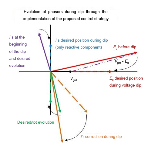
1. Introduction
As wind power increases its share of total energy production, more and more responsibility must be assumed by wind turbine generating systems, or WTGSs. In consequence, WTGSs will be required to guarantee the stability and reliability of the grid in a wide range of situations.
One of the disturbances that may be suffered by any electric device connected to the grid, is a voltage sag. A voltage sag is a sudden reduction in potential in the electric grid, followed by a rapid return to its normal value. This situation may occur due to grid faults, line-to-ground faults being the most common. Other examples are line-to-line, and tri-phase symmetrical faults. Voltage sags may also occur due to switching on/off such as the start-up of high power motors which have been connected directly to the grid.
Voltage sags do not produce identical effects on all wind generation technologies [1]. Those based on doubly fed induction generators are vulnerable to voltage dips as the effects of these faults on the generator can be potentially harmful if no protective measures are adopted. Traditionally, in the event of a voltage dip, these generators were automatically disconnected from the grid, thus introducing additional disturbances to the grid. Recently, to avoid their disconnection, protection equipment, such as crowbar devices, has been designed to protect the machine rotor as well as the power electronics devices connected to it.
Numerous publications have been issued concerning the behavior of DFIG-based wind generator systems during grid perturbations such as voltage sags. Some of these studies also propose solutions that may allow the wind generator to withstand the grid fault without temporary disconnection, while supplying reactive power to the grid, thus contributing to grid voltage restoration.
The most widespread commercially implemented solution that protects a DFIG-based system from voltage sag, is the addition of a crowbar device. These devices are either active or passive, depending on whether they are able to modify, or not, their resistive component during operation. The objective of these systems is to evacuate excess energy from the machine rotor during the first instants of symmetric voltage dips [2] or during unbalanced dips [3], taking into consideration the limit ratings of the rotor converter [4], which is especially relevant since increasing these ratings would ameliorate some of the existing solutions to the problem in question.
Another possible solution that can be compared with a crowbar is the implementation of systems that add passive impedances in series with the machine stator. These impedances limit the undesired effects of voltage sag on stator flux by assisting the machine's control of rotor current reduction, and by limiting the current exchanged with the grid during the voltage dip [5].
Among alternatives to the use of crowbar systems, those that include voltage restorers should be mentioned. These systems compensate the voltage drop during a sag, as explained in [6,7], so that the wind generator does not suffer the grid disturbance. Voltage restorers may present the advantage of being implemented in an existing installation without modifying the wind generating system. However, they can be voluminous and expensive. They often require the use of transformers that represent a continuous power loss while the usage of the device is only eventual. Studies need to be done so that these devices use minimal energy. In [8] different energy optimizing techniques are reviewed, while [9] presents a procedure that eliminates the use of a transformer.
There are other approaches that study machine behavior in detail during a voltage dip in order to propose an adequate modification of the machine's control during the mentioned fault. These last solutions have the great advantage of not requiring additional devices that increase maintenance and installation costs. For example, excess energy during a voltage sag can be drawn from the machine by allowing the turbine to accelerate, thus avoiding the use of external crowbar type devices [10]. However, wind turbines have a high inertia, which can hinder the rapid switching on/off required during the fault.
Another set of solutions focuses on stator and rotor currents, and their physical effects on the machine during voltage sag. Among the proposed solutions, there are strategies that intend to compensate, via rotor control, the effects of electric transients created by voltage dip, such as [11]. In this reference, it is suggested that a voltage should be imposed at the rotor in phase with that induced at the stator, but the physical implementation may not be simple since it requires two PI controllers. Adjusting them can be difficult, as their effectiveness depends on the accuracy of the machine parameters. Other solutions [12,13], propose similar strategies that include a coordinated specific control of the grid-side converter. These last procedures increase the reactive power delivered to the grid, actively assisting voltage-level restoration. On the other hand, the contribution of the rotor-side converter is limited by its name-plate power rating, which is small when compared to that of the stator. Therefore, what should be addressed with special care are those strategies that offer significant improvements in stator behavior during the voltage dip.
Moreover, solutions should be considered that calculate the current that must be injected into the rotor in order to achieve a perfect compensation of the current that is present at the stator [14]. This is a similar idea to the first control method proposed in this paper, with the difference that in [14] the authors only try to mitigate the over-currents caused by the fault without taking into consideration the active and reactive power references imposed by Grid Codes during a fault. Other studies impose a fixed current at the rotor during voltage sag and demonstrate the good response obtained in fixing the rotor current, while evaluating the influence on DFIG behavior with different parameters that describe a symmetric voltage dip [15]. Special concern is dedicated in [15] to study the effects of the type and duration of the fault, including its recovery, and distinguishing between an abrupt and discrete recovery sag. However, the control solution proposed consists of imposing a constant fixed current in the rotor during the fault, equal to its pre-fault steady-state value, with the purpose of ensuring that the system rides through the fault with acceptable current levels. Although this study is remarkable, the solution proposed does not imply the DFIG contributes to fault recovery as it should do in accordance with Grid Codes.
Finally, [16] stands out for its analysis of the state of the art of voltage dip mitigation solutions, and the thorough preliminary study of DFIG system behavior during a symmetric voltage dip. This study leads to the proposition of reducing the effects of voltage dip via the quadrature component of the rotor current (Irq), with the objective of damping the oscillatory parcel of the magnetizing current, and thus mitigating the disturbance of the stator currents tied to the magnetizing current due to stator linkage. The proposed strategy ameliorates machine behavior, but does not fully solve the challenges to which DFIG-based systems (machine and power electronics devices) are confronted during a dip, as current and voltage levels imposed on the machine rotor are not directly limited. The novelty of the method proposed in this paper which tries to improve the work presented in [14–16], is that it keeps the rotor current limited during the voltage sag while the wind generator follows the imposed grid code.
Thus the intention of this article is to contribute to the search for a robust and reliable solution that allows DFIG-based wind generators to withstand voltage dips, using a solution which is simpler and more robust than the ones presented in the literature. In keeping with the referenced works, this paper proposes a new control strategy based on a simpler solution that controls rotor current and provides DFIG type WTGS low voltage ride through (LVRT) capability, ensuring that all the machine's relevant electric parameters (voltages and currents) are within acceptable ranges. Above all, the generator is continuously controlled, and able to comply with Grid Code requirements, without disconnecting from the grid and without the need of additional devices.
The objectives of the proposed control strategy are: controlling the total machine magnetic flux and avoiding iron saturation; limiting rotor currents to a value that does not endanger any of the rotor components; delivering through the stator a limited reactive current to the grid; and making the use of devices such as a crowbar, unnecessary. Among the benefits obtained from crowbar removal, the most advantageous are the elimination of the cost of the device itself and that of its installation; the reduction of occupied space in the nacelle; and the elimination of extra weight and supplementary maintenance. Moreover, it should be taken into account that the usage of a crowbar during voltage sag implies, firstly, an energy loss in the crowbar's passive elements, and secondly, a triggered disconnection of the rotor from the power electronics devices that govern machine behavior. Thus, there is an instantaneous loss of machine control.
2. Description of the Proposed Control Strategy
The proposed control system has been developed from a transient model of a DFIG machine where the currents, voltages, flux linkages and other electromagnetic variables have been represented by space phasors.
The position of the stator and rotor fluxes is especially relevant as the angle between these two fluxes establishes the machine electromagnetic torque and their vector sum establishes the electromotive force, EMF, induced at the stator and rotor windings. These flux positions will be obtained directly through the space representation of the machine currents.
Consequently, the machine operating point can be easily and efficiently determined at all times, as the space-phasor representation offers a clear visualization of the mentioned parameters. Thus, the space-phasor representation assists in the conception and design of the proposed control strategy, as well as providing a physically implementable flux control method.
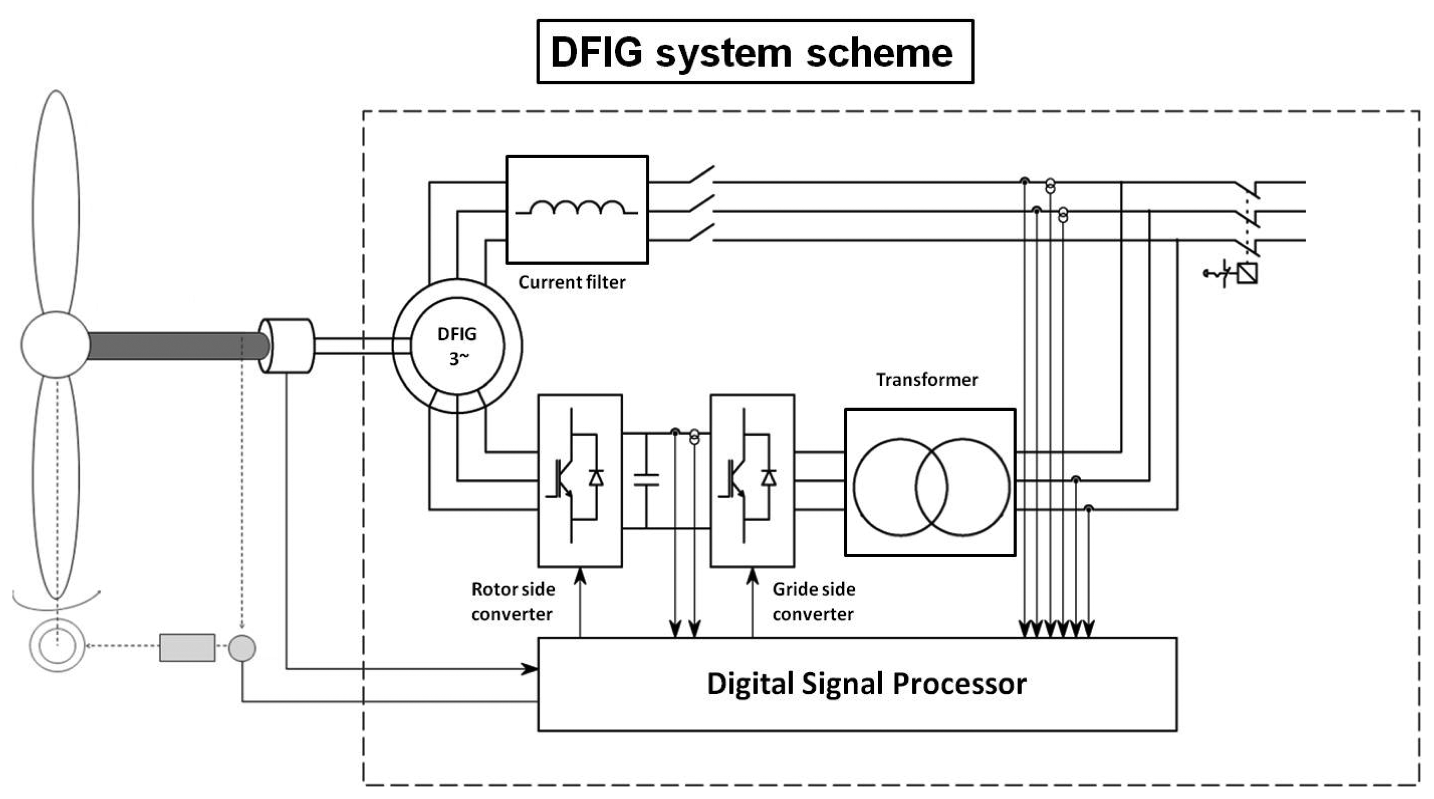
Figure 1 represents schematically the DFIG system that is going to be studied. The stator is connected to the grid through an inductive choke coupling coil; the rotor is connected to the grid through a transformer. Between the rotor and the transformer, the rotor line is equipped with two identical converters connected back-to-back. These converters are able to impose a set of controlled currents on the rotor that govern machine behavior through an adequate positioning of the rotor magnetic flux.
From the diagram above, it can be deduced that the stator current, and therefore the stator flux, is tied to the grid while the rotor current and rotor flux will remain independent from the grid, as long as converter limits and energy storage capacity in the DC-link are not exceeded.
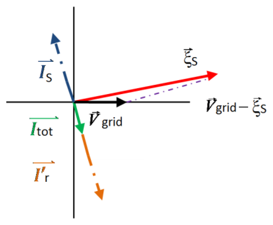
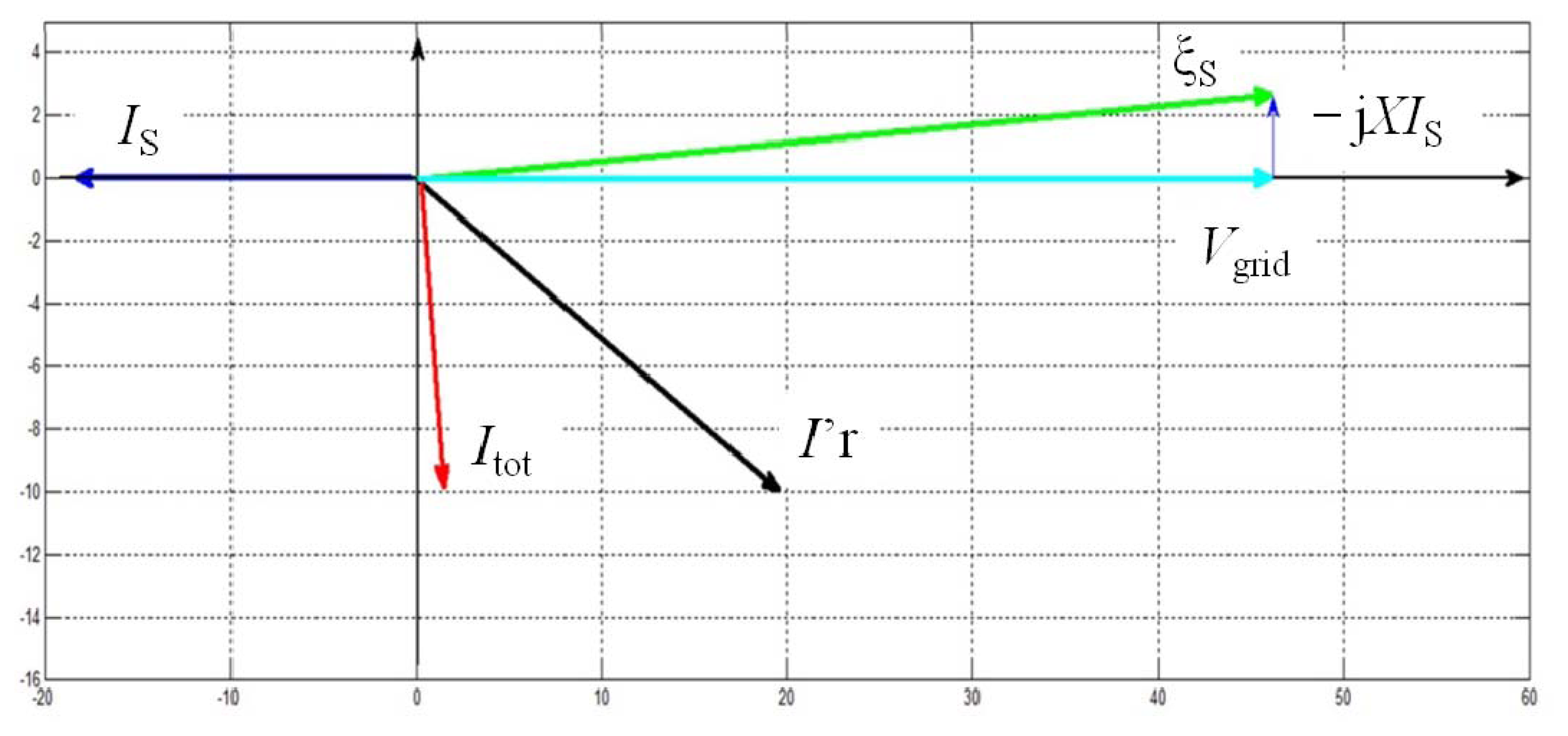
Figure 2 represents the space phasor locations in a typical steady-state working point for a DFIG WTGS. The variables shown are: grid voltage, Vgrid; voltage induced at the stator terminals, ξS; the stator current, IS; the rotor current referred to stator variables, I′r. All these variables can be easily related to the DFIG diagram shown in Figure 1.
In addition to all these variables, Figure 2 represents total machine current, Itot. This last current phasor is the vector addition of the stator and rotor current phasors. It is therefore a virtual variable as it does not represent a current through any physical winding. However, its representation is crucial as it coincides with the position and magnitude of the total machine magnetic flux (which exists physically).
The variables mentioned above are referred to an axis which is aligned with the phasor that represents the grid voltage as seen in Figure 2. Rotor and stator currents are represented using a motor criterion to facilitate their visualization and interpretation.
It is convenient to establish mathematical expressions in order to relate the phasors shown in Figure 2. However, it is necessary to analyse the variables involved individually before establishing their mathematical relation.
IS: represents the stator phasor current shown in Figure 2. It can be evaluated as the ratio between the voltage drop at the inductive coupling coil represented in Figure 1 and its impedance value given by RS and XS parameters.
Considering that the electric coupling between the stator and the grid is mainly inductive, the resistive component RS is usually ignored. As a result, the IS phasor is determined as in Expression (1).
I′r: represents the rotor current phasor referred to the stator. The rotor side converter can impose at all times any value of I′r within its operating limitations.
Itot: represents the vector addition of IS and I′r as in Expression (2).
ξS: represents the induced voltage at the stator terminals which is tied to the time derivatives of both the stator and rotor fluxes. These fluxes are proportional to the currents through their windings, their constants being proportionally equal to the value of their self and mutual inductances. Due to the fact that the rotor current phasor has been referred to the stator reference frame, the rotor contribution to ξS can be considered as proportional to the machine mutual inductance, L. The resistive component of the machine windings will be ignored.
Furthermore, the mutual inductance, L, being similar to the stator inductance (Ls = L+ LσS, where LσS is the stator leakage inductance), ξS happens to be approximately proportional to the time derivative of Itot (3).
Therefore, the mathematical expressions that relate the phasors shown in Figure 2, and that follow the assumptions described above are:
These expressions can be further studied. Expression (1) shows that the stator current phasor IS is always delayed 90° with respect to the voltage drop phasor V⃗grid − ξ⃗S. This implies that the magnitude and position of the IS phasor and, consequently, the value of the active PS and reactive power QS delivered to the grid by the DFIG system, can be modified through the control of the position of the induced voltage phasor ξS.
Expression (2) shows that by controlling the rotor current phasor I′r, Itot is modified. Therefore, the total machine flux can be regulated through I′r.
Expression (3) implies that the position of the magnetizing current phasor Itot is always delayed 90° with respect to the position of the induced voltage phasor ξS. This means that the magnitude and position of the induced voltage phasor ξS, can be directly controlled through the magnetizing current phasor Itot.
Expressions (1)–(3) are only applicable when the DFIG system is under control and its relevant variables are close to their rated values. This is not, however, necessarily true during the event of a voltage sag, which is explained as follows:
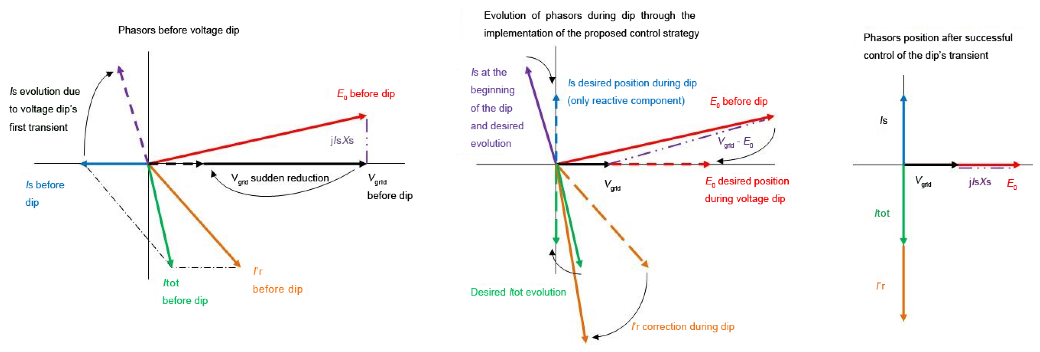
In the event of a voltage dip, V⃗grid drops rapidly increasing the value of the V⃗grid − ξ⃗S phasor as well as modifying its position. Consequently, the stator current is disturbed, its value increases and its position is altered, following the evolution of the V⃗grid − ξ⃗S phasor as shown in Figure 3.
If the system does not respond to the grid disturbance, the transient introduced by the voltage dip will not be damped and Expressions (1)–(3) will no longer be valid, while Is and I′r will attain unacceptable values.
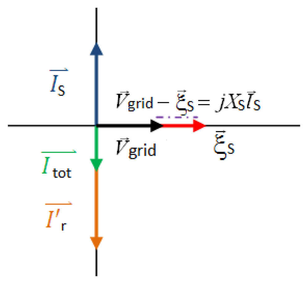
The proposed strategy intends to control the voltage dip transient and to fix its variables in a way that allows the DFIG system to deliver the maximum possible reactive power (Qs ∝ Vgrid IS Max) to the grid during the voltage sag. This power, for the moment, is limited by the maximum stator current. On the other hand, and also according to the grid operating code, the active power Ps must be equal to zero during the voltage sag. Thus, the objective is to control IS ensuring that its magnitude and position imply a controlled amount of purely reactive power delivered to the grid. This will be achieved through the positioning of I′r. The following figure, based on Expressions (1)–(3), illustrates the situation sought through the implementation of the proposed control strategy:
In Figure 4, the Vgrid and ξS phasors are aligned, meaning that no active power is being delivered to the grid. On the other hand, the IS phasor has a 90° lead when compared to Vgrid. This is coherent with the fact that only reactive power is delivered to the grid. Further detail on the relationships between ξS, Vgrid, IS, Ps and Qs, and the model which has been used, can be found in reference [17].
The value and position of IS are determined by that of the ξS phasor. ξS is proportional to the value of the total magnetizing current Itot, and is placed 90° in advance with respect to this phasor. This last variable should be modified in order to achieve the desired value of ξS and thus of IS.
The rotor side converter will place I′r according to the commands it receives. As the desired position of the Itot phasor is well-known, (that shown on Figure 4), and is the result of the vector addition of the IS and I′r phasors, the set point value for the latter can be determined as:
It is important to remember that the system will be controlled through the modification of I′r. A practical implementation of this strategy will now be presented.
It has been established that a convenient value for the stator current phasor during a voltage dip, (IS,dip) is that equal to two times the rated current (ISN). Limiting stator currents also ensures that rotor currents do not rise to unacceptable values.
IS can be limited by ensuring that the V⃗grid − ξ⃗S phasor does not increase uncontrollably. As V⃗grid cannot be varied, this limitation is achieved by restraining the value of ξS through Itot. For example, to ensure that stator currents are beneath two times their rated value, following the Expression (1), it is possible to write:
Expression (6) establishes that a reduction of the phasor ξS is needed for the limitation of the ISN current. The desired proportional reduction of |ξS| can be calculated using the following expression:
|ξS| is proportional to |Itot,before dip| as it is suggested in Expression (3). Therefore the reduction coefficient r will be directly applied to |Itot|. This provides immediate control of ξS which avoids the development of currents that saturate the machine and prevent the DFIG system from following further control commands.
Once the magnitude of |Itot| is calculated, its position must be also decided. Knowing that the machine must deliver purely reactive power, Itot can only be placed in the position shown on Figure 4.
The following step consists of calculating the current that must be imposed on the rotor to achieve the desired magnitude and position of the Itot phasor. This task is straightforward once all the relevant phasors that establish the machine working point are referred to a reference frame where the x-axis is defined by the Vgrid space phasor. This is the reference chosen in Figure 4.
It is important to recall that Itot was defined in (2) and that the necessary rotor current I′r was defined in (4). These two expressions can be projected into the mentioned x and y axis. This determines the current that must be imposed on the rotor. Firstly, regarding the horizontal x-axis, I′r must be able to compensate the stator current phasor horizontal projection. This will ensure that the current delivered to the grid through the stator is purely reactive. Secondly, the rotor current's y-axis component must be modified in such a way that the magnitude |Itot| is appropriate. The following expressions represent the implementation of the proposed control strategy:
The rotor side converter will follow these last two expressions throughout the voltage sag. It is interesting to note that the value of r will vary with Vgrid so that the machine can increase the amount of reactive power delivered to the grid during voltage recovery without exceeding the accepted value of IS.
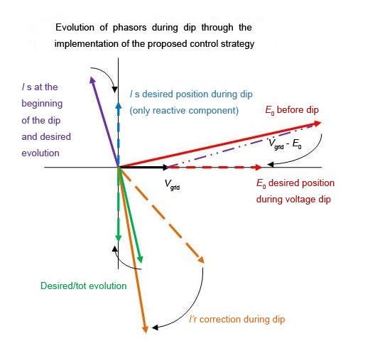
To sum up, Figure 5 is presented. This figure illustrates the effect of the transient state introduced by the voltage dip, the effect of the proposed control strategy and the evolution of the relevant electric variables attained during the voltage sag through the correction of the rotor currents as suggested in Expressions (8) and (9).
3. Improvement of the Control Strategy
During the experimental validation of the described control strategy on a laboratory test-bench, its physical implementation led to unexpected difficulties that hindered the correct operation of the machine during the tests that were carried out. The laboratory test-bench has limitations of its own, meaning that the electric variables, that need to be known at every instant in order to define the precise position that the I′r phasor must adopt, were not always determined with sufficient accuracy. The measurements of the relevant electric variables were exposed to electric noise that could not be easily eliminated and had a certain level of lag that led to an inexact and unreliable calculation of the space phasors. Although this proposed control method needs more tests and clarifications in order to complete a full study of its capabilities, due to the referred limitations it was decided to modify the previous control strategy, leading to a second strategy that should be more robust and simple to implement. The main objective of this new approach is to eliminate the need of measuring the stator currents at all times for the definition of I′r through IS. By doing so, the number of variables involved is smaller, reducing the uncertainty level, and errors in the mathematical operations. Thus, the new approach consists of a simple open-loop current control which imposes an I′r phasor during the voltage sag, with a desired amplitude and position that has been previously calculated.
This current control method assures rotor current limitation during the fault, since its instant value is imposed at any time by the control, and its exact position is determined through a series of previous tests. These tests consisted of imposing a reduced voltage on the machine terminals while turning at a constant speed. In this situation the machine was governed in such a way that the active power exchanged with the grid was at all times zero, while increasing the reactive power delivered to the grid until either I′r or IS reached their accepted maximum.
These tests help to precisely determine the position that I′r should adopt in order to deliver the maximum possible reactive power to the grid during a voltage sag situation. This position is the desired set point of I′r during the voltage sag. What will be proven is that this position, determined through steady-state test conditions, eliminates the potentially harmful effects of the transient currents caused by voltage dips.
To sum up, the modified strategy consists of imposing a set of currents on the machine rotor, when the position and magnitude associated with space phasor I′r are well known thanks to the previous tests performed. Therefore, the difference introduced with respect to the previous solution presented in Section 2, is that the rotor phasor location is not calculated mathematically during the voltage sag. In contrast, the phasor position is now imposed thanks to an intrinsic knowledge of the machine and its position is left unchanged during the whole duration of the voltage sag.
Placing I′r in a fixed position, avoids continuous corrections on Itot that proved to affect ξS more than expected. This motivated further disturbance to IS that was added to those introduced by the voltage sag's first transient. The new placement of I′r has a direct but more subtle influence on the Itot phasor which will keep ξS under control and, finally, IS. In consequence, all the machine's electrical variables are now governed by the control strategy and not by the sag transient. Thus, the machine evolves quickly to a new operation point where grid requirements are respected. It should be noted that this simple and robust control solution is only applicable during the short time the fault lasts (1–2 s).
4. Computer-Based Simulation
The modified control strategy explained in Section 3, based on the original strategy proposed in Section 2, has been designed and simulated in a model using the numerical computing environment Matlab-Simulink (Mathworks, MA, USA).
The model is made up of a series of subsystems that emulate the different elements of the WTGS. These are: the grid, the turbine, the wound-rotor induction machine as well as the calculation of all physical variables that intervene. Some examples are: rotor speed, voltage and current values at the stator and rotor terminals, electrical power exchanged with the grid, and mechanical power obtained from the wind, depending on wind speed, turbine pitch angle and angular velocity. The different controllers or governors that modify the WTGS behavior, such as a Maximum Power Tracker controller, have also been implemented in the simulation model.
The model mentioned above has been conceived using the constructive parameters of a commercial 2MW DFIG wind generator. The nameplate characteristics of the generator are shown in Table 1:
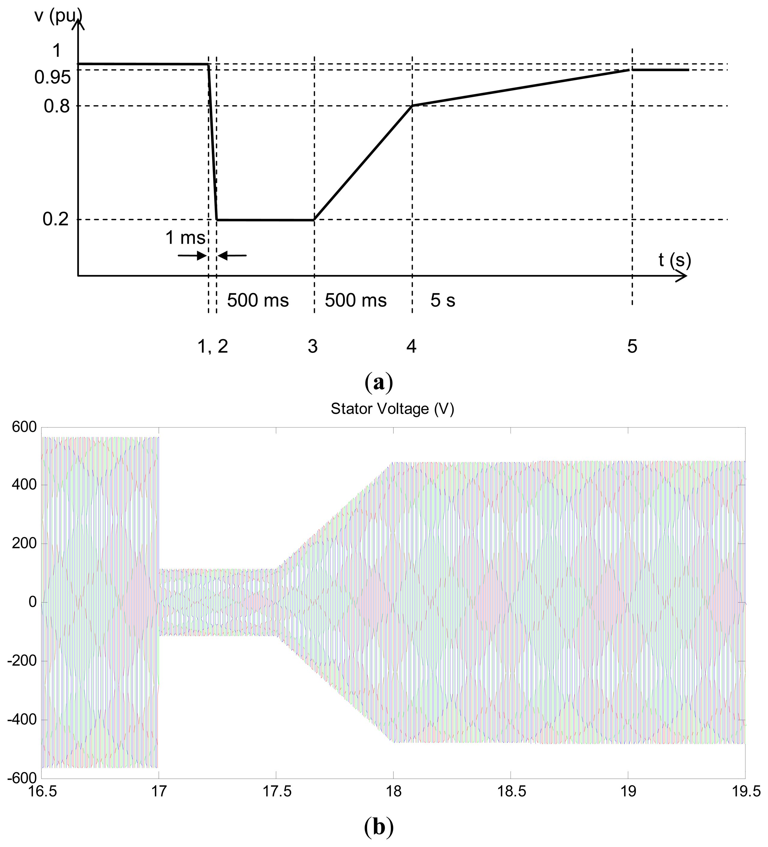
The results that are going to be presented were obtained after simulating a three-phase symmetrical voltage sag while the generator is operating at its rated power. The profile of this voltage sag (Figure 6) corresponds to the standard established by the Spanish national grid operator, REE [18].
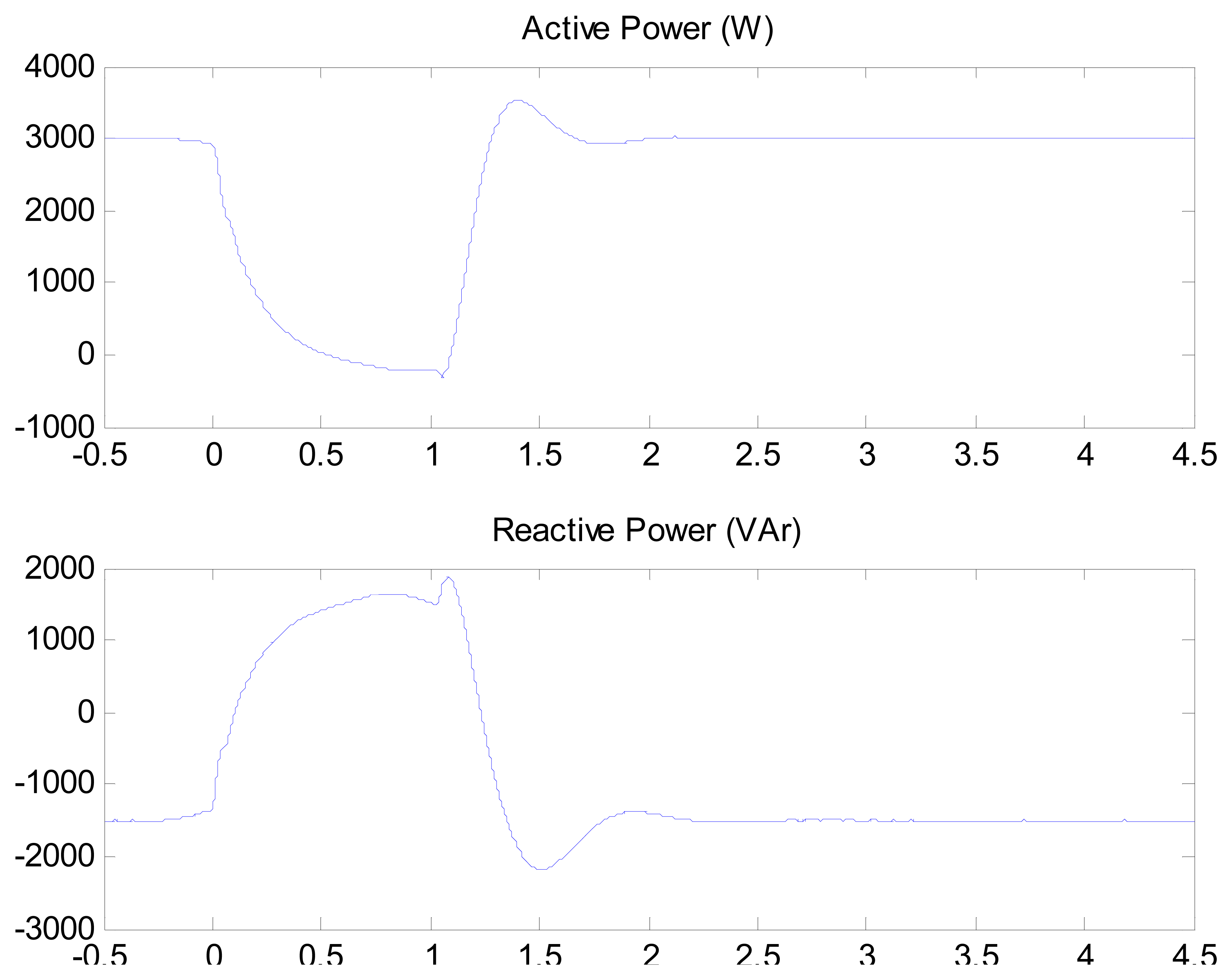
It can be observed how the active power exchanged with the grid rapidly reduces to a near zero value while the reactive power increases to a value where the stator currents achieve their maximum permitted level. The proposed strategy works well, although the rotor currents have not been perfectly controlled, as the rated voltage level on the DC link between the two power electronics devices was not sufficient during the extreme fault that was simulated. This provokes an irregular evolution of the power exchanged with the grid. It should be noted that if an increase of the maximum DC bus voltage is considered, which would imply increasing the voltage ratings of both power converters, the desired rotor current needed to ride through the fault would be available without any problem. Note that the rotor rated voltage allows increasing the DC bus voltage, and this change would not be difficult or expensive to carry out.
With regard to the limited voltage available in the DC bus, the simulated voltage dip provokes a transient that creates a direct current component at the rotor. This current can be understood as a phasor that has a constant direction on the rotor reference frame. However, the phasor rotates when seen from the stator reference frame, meaning that it will induce, through the machine's mutual inductance, a low frequency disturbance on the stator currents. This disturbance causes the small power oscillations that can be seen in Figure 7.
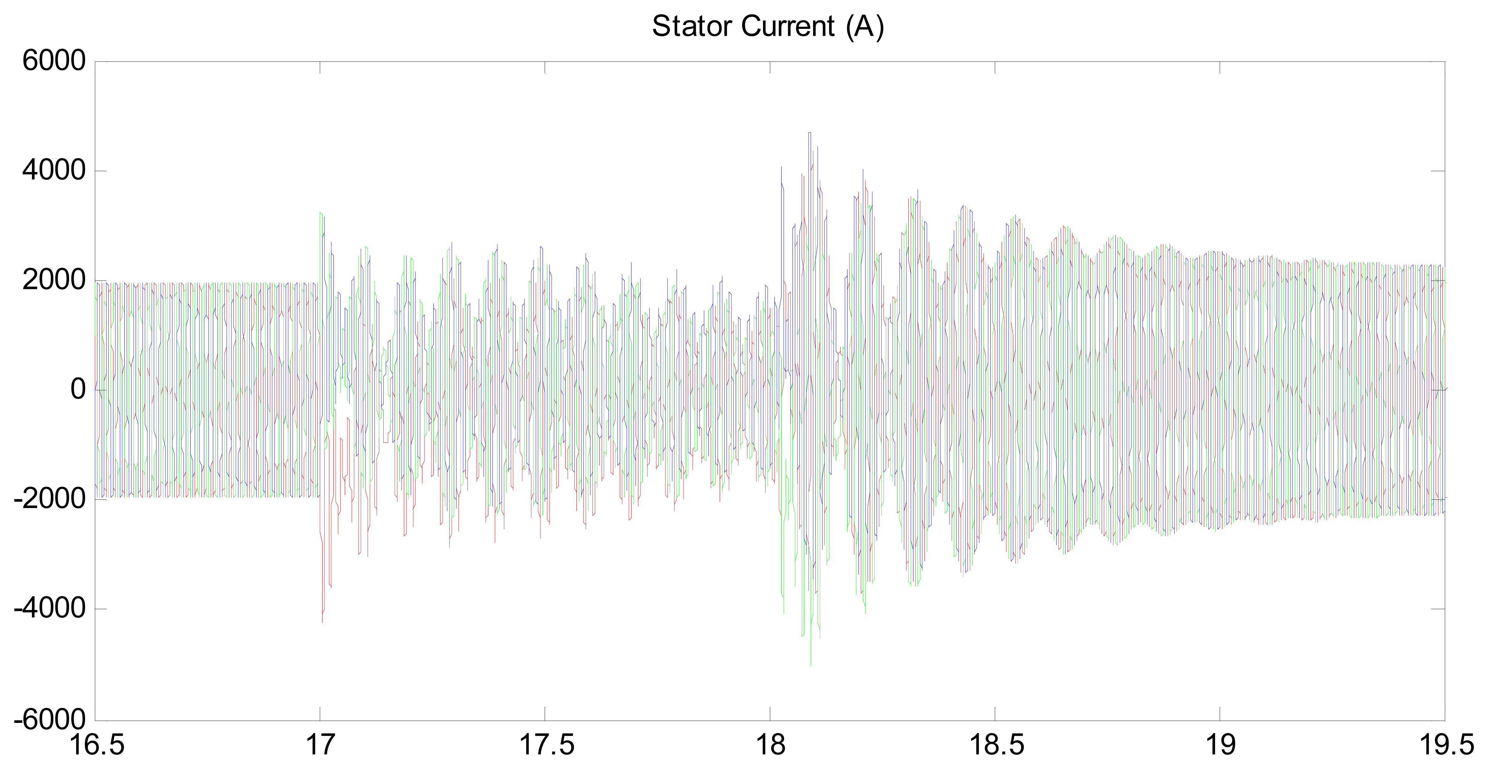
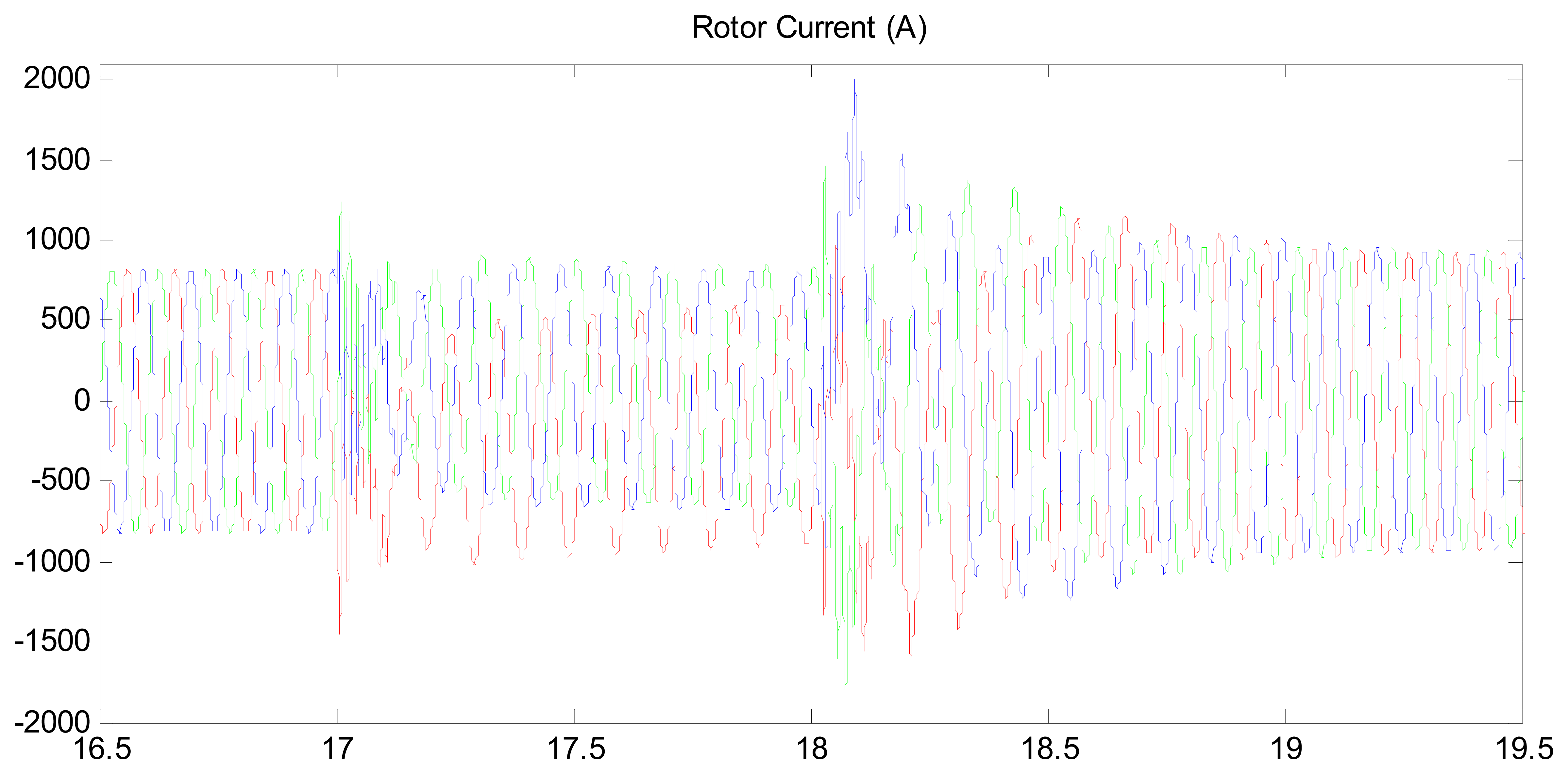
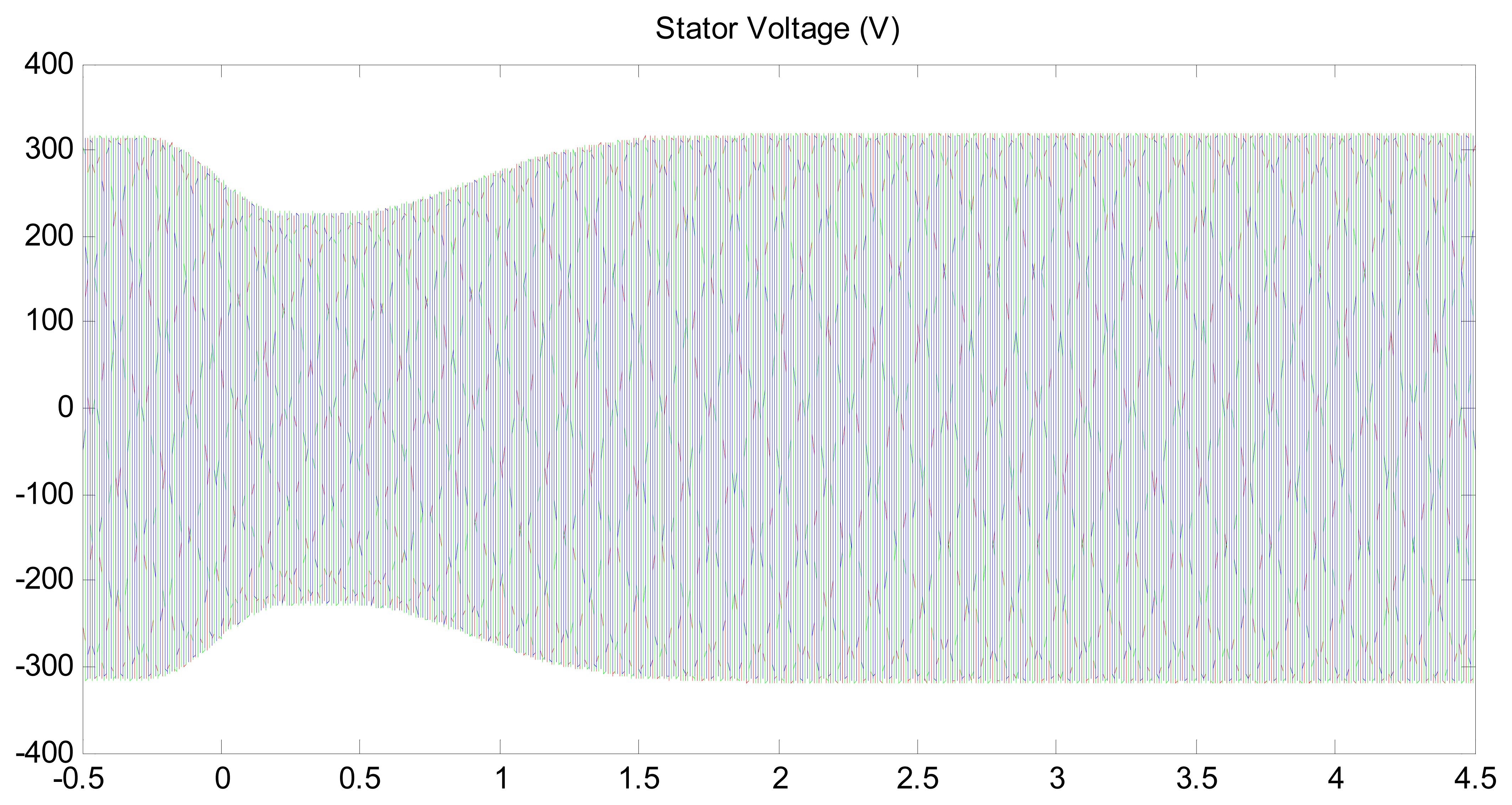
The stator currents achieve peak values that reach two times the rated value (Figure 8). This is not a problem, due to the brief duration of the fault and the robustness of the stator windings. On the other hand, the rotor system, which must be protected from high currents, presents peaks that are slightly beneath two times their rated value (Figure 9). When the voltage dip is detected, the proposed method begins to work imposing a rotor current which is limited by the control system, as stated in Section 3, “Improvement of the control strategy”. This would mean that the first peak at t = 17 s is beneath the limit value that has been previously stated for both converter and rotor. In this case it has been chosen to allow a rotor current which is two times the rotor rated current. The second current peak, after t = 18 s, coincides with the change of the voltage sag control strategy to the default machine control (Maximum Power Point Tracking strategy). The described current peak is therefore in close relation with the way the machine control has been coded. It is thus possible to fully eliminate this second transient but it does not represent a priority in the solution presented here. These peaks have a short duration (less than 20 ms) not representing, therefore, a risk to the electronic power devices, since typical power IGBTs allow ICRM (repetitive maximum collector current) of two times ICnom, under a correct temperature [19].
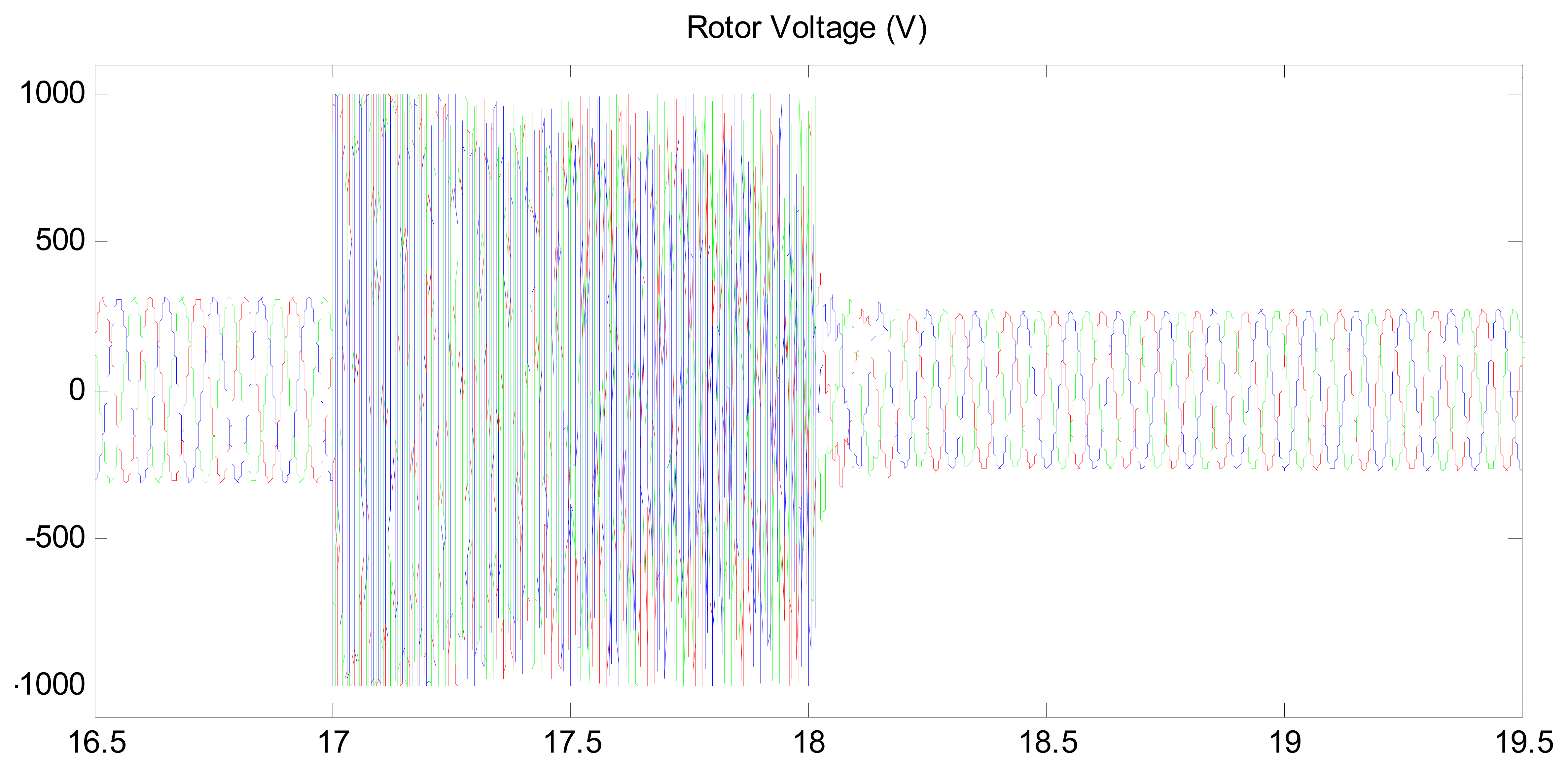
In Figure 10 the rotor voltage is represented. This voltage is limited to the real installation rated level but, as stated before, it could be increased in case an improvement in rotor current control might be needed. The rapid increase of the rotor voltage is a direct consequence of the imposed sudden variation of the rotor currents to which inductive circuits always tend to oppose.
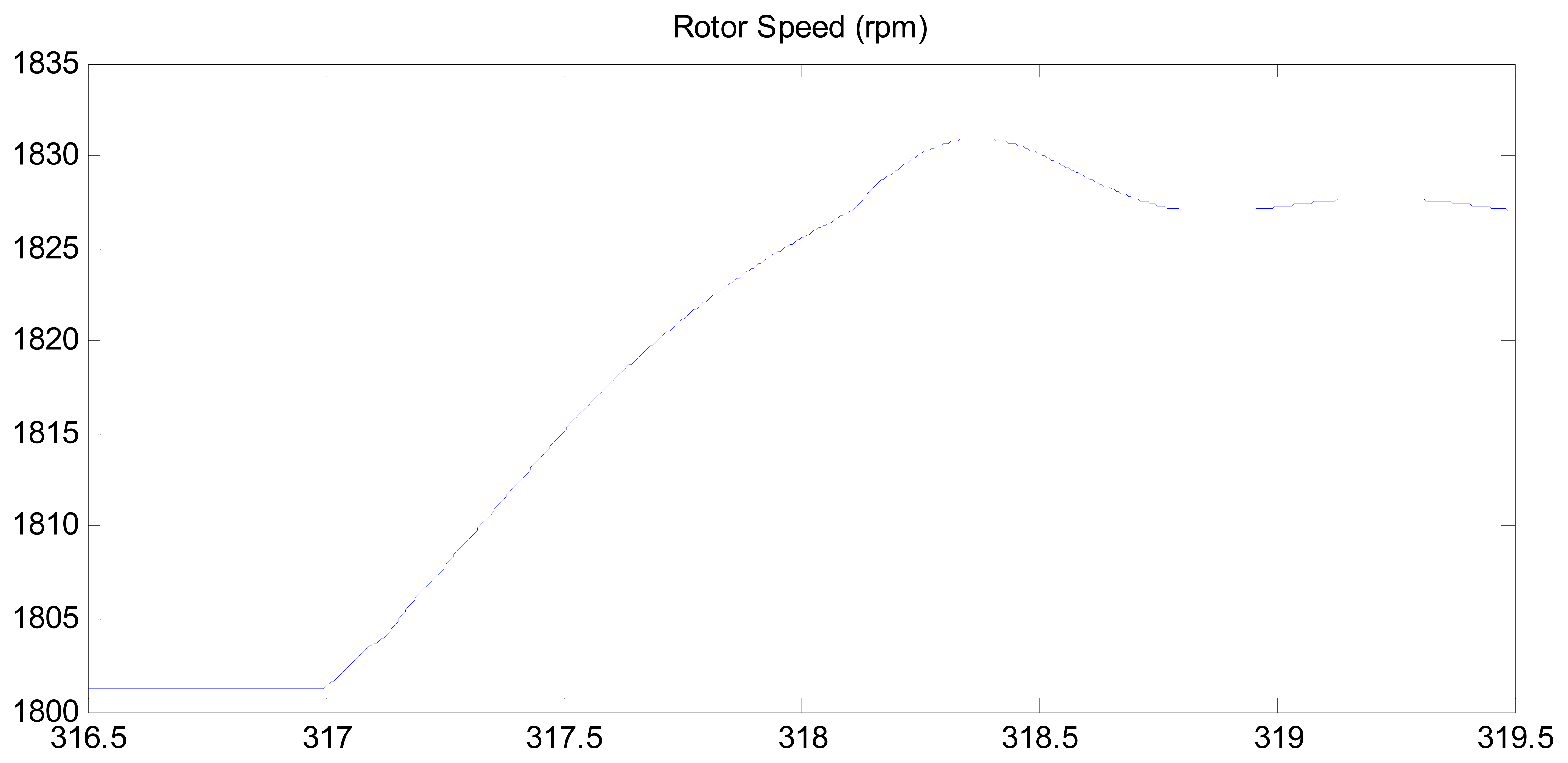
It should be noted that during the voltage sag, active power delivered to the grid (zero) is not balanced with the mechanical power obtained from the wind turbine. This causes an acceleration of the wind turbine that in any case will be dangerous due to the exceptional moment of inertia of the turbine itself. In Figure 11 it can be seen that the expected acceleration is only 40 rpm which is less than a 2% increase.
The 40 rpm increase on the machine rotor represents a 0.4 rpm increase of the turbine's rotating speed that can be considered as negligible. To sum up, it may be concluded that the modified strategy is able to control the WTGS, and results in a situation where power delivered to the grid is purely reactive, as required by grid operators. Moreover, the strategy allows maintaining rotor currents below dangerous levels, with a voltage at the rotor terminals that can be handled by the electronic power devices, eliminating the potentially harmful effects of the voltage sag without the use of additional devices, and without losing control of the machine. In the case of an increased DC-bus voltage rating, the proposed rotor current control can be perfectly performed without any power oscillation and the transients described for the extreme standard sag that has been simulated.
5. Experimental Results on Laboratory Test-Bench
In order to test the viability and physical implementation of the proposed strategy, experiments have been carried out on a scale WTGS prototype developed by the ETSII-UPM's Electric Machines Laboratory [17], which specifications are shown in Table 2. The tests used the modified strategy, that is, imposing a fixed rotor current space phasor during the voltage sag.
The purpose of the test presented here is only to prove that the strategy proposed in Section 3, which has been simulated in Section 4, is physically implementable in a real installation, and works well although the sag created does not correspond with the standard simulated. The voltage sag during the test was simulated using a variable autotransformer that connects the induction generator to the grid. The imposed sag had 40% depth and the machine operating conditions chosen were: 3000 W delivered to the grid and 1500 VAr absorbed form the grid. At this working point, the rotor currents achieve their rated value.
Figures 12–14 are obtained from data supplied by the specific experiment software that governs the machine via the command of the power electronics devices connected to the rotor and from the measures made of the different electric variables with Hall Effect sensors. Figure 15 shows the actual rotor currents measured by a high precision digital oscilloscope.
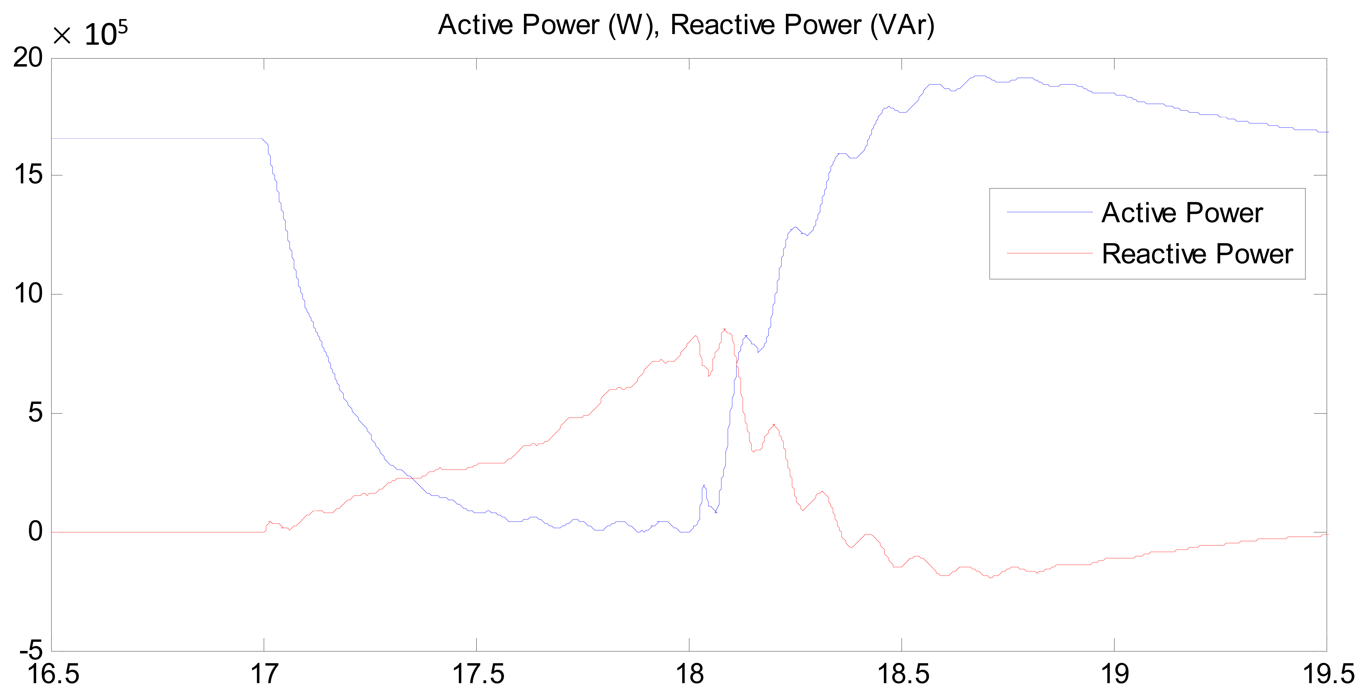
Figure 12 shows the disturbance imposed on the test-bench. Figure 13 shows the active and reactive power exchanged with the grid, illustrating how the control strategy reduces the active power to zero, while increasing the reactive power delivered to a point where the rotor currents achieve their permitted maximum.
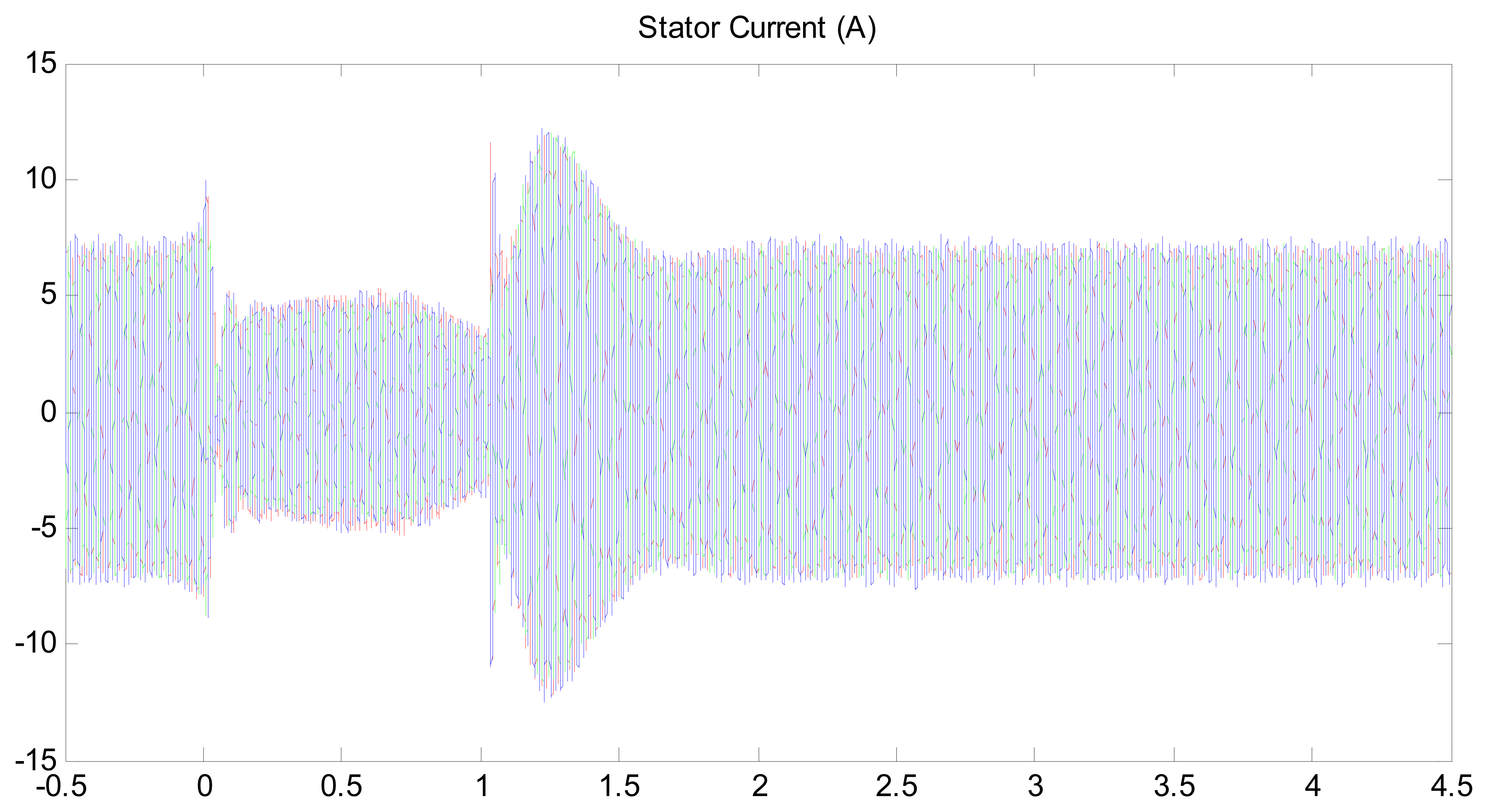
Figure 14 shows the evolution of stator currents which have been greatly reduced due to the decrease of the total apparent power exchanged with the grid. These currents are well below their rated value (13.3 A rms for the machine that is being used).
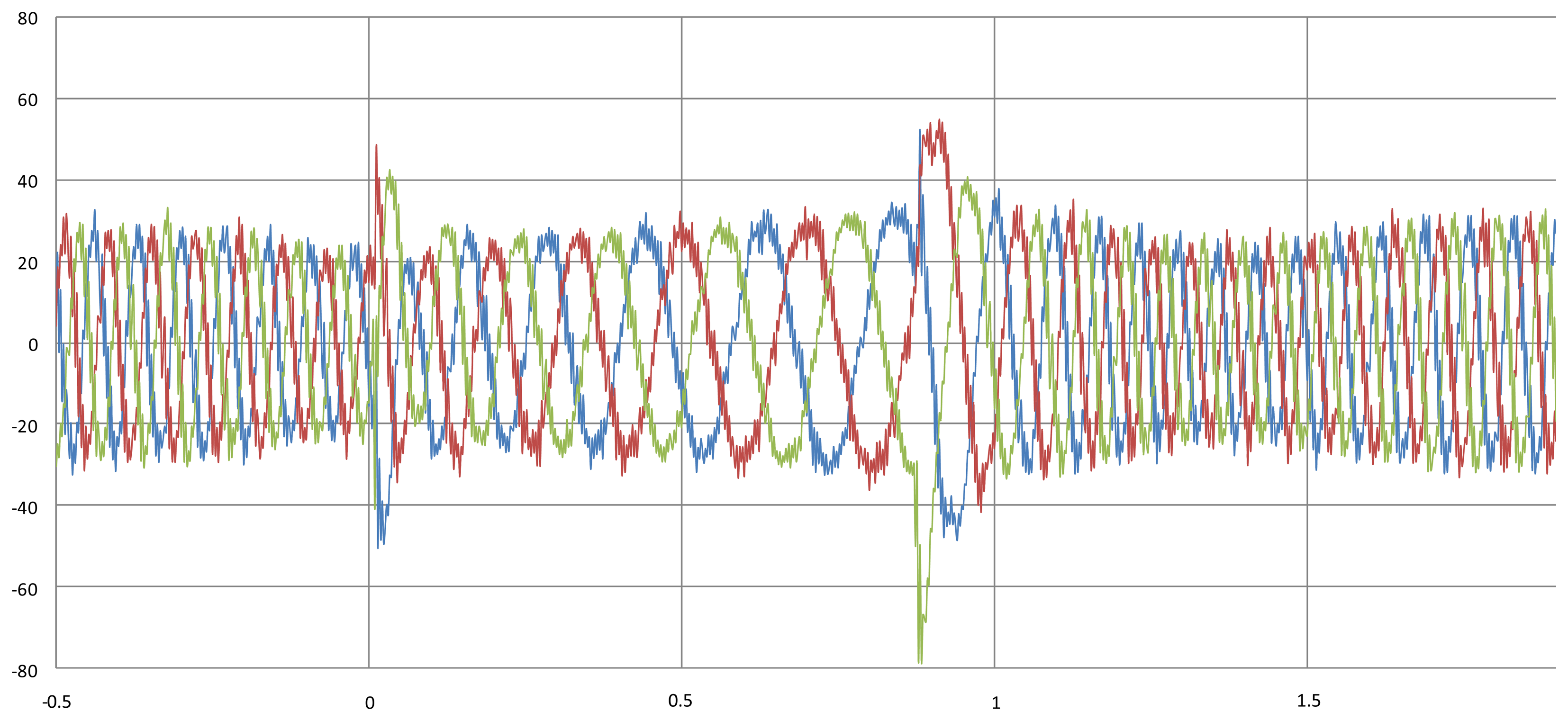
Figure 15, however, shows that the rotor currents reach two times their assigned value (21 A rms). During the experiment, it has been proven that the actual rotor currents exceed this limitation at two given instants (see Figure 15). The first current peak is extremely brief, not representing a real concern. The second current peak coincides with the change of the voltage sag control strategy to the default machine control (Maximum Power Point Tracking strategy). The described current peak is therefore in close relation with the way the machine control has been coded. It is thus possible to fully eliminate this second transient but it does not represent a priority in the solution presented here.
As previously noticed in the simulation, the machine accelerates during the experiment, as shown in Figure 16, due to the reduction of the electric power delivered to the grid. This acceleration is substantial due to the fact that the system that emulates the wind turbine (a DC motor) has a much smaller relative inertia compared to that of a real wind turbine.
The experiments also had the intention of studying the behavior of power electronics devices connected to the rotor as well as the voltage level of the DC link between them.
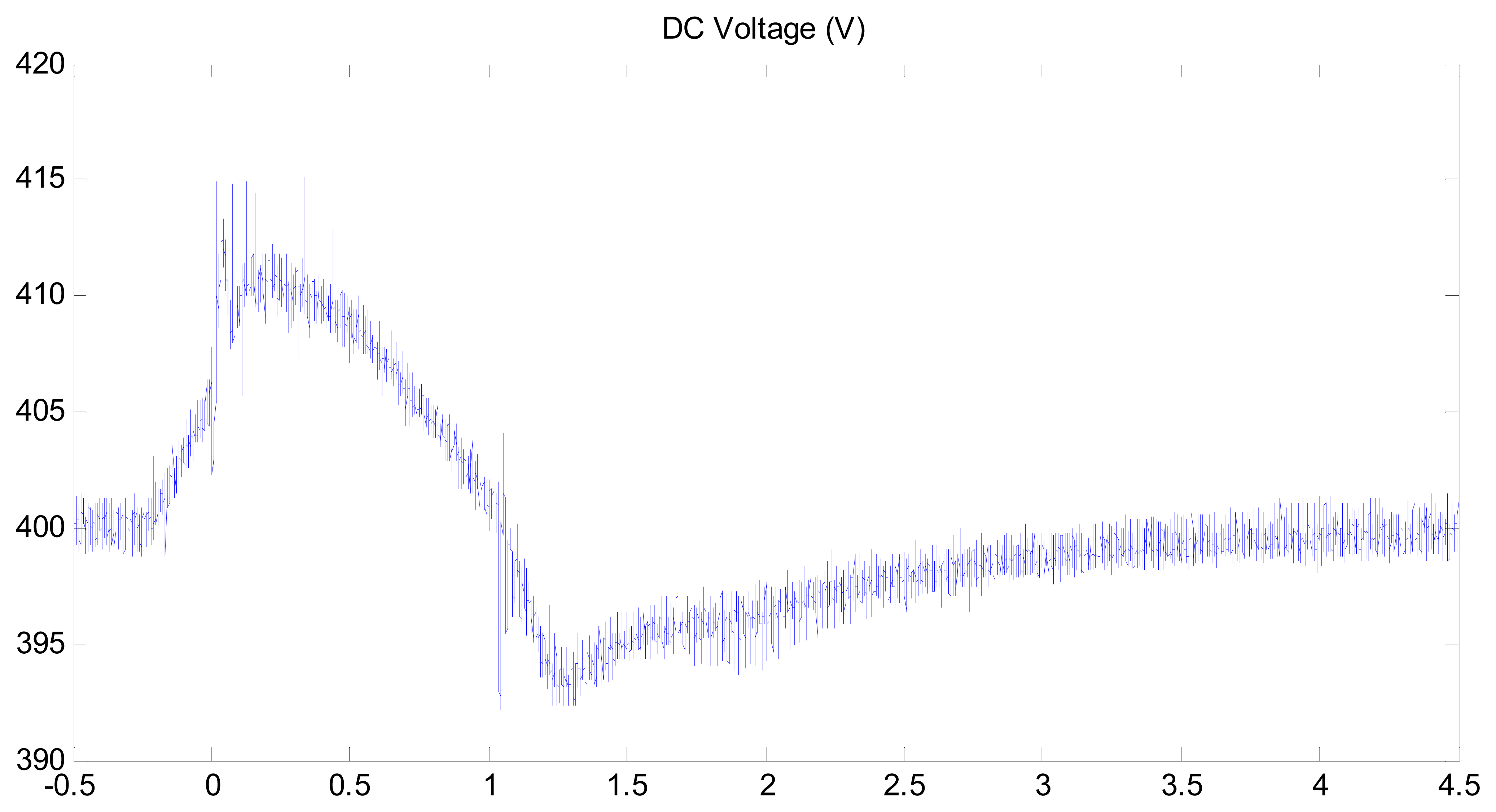
Figure 17 shows that the DC voltage rises during the grid voltage dip due to the rapid response of the regulators that control the grid-side converter, but the DC voltage level varies within a narrow range.
The power exchanged by the rotor and the grid-side converter was also studied. Figure 18 illustrates how power at the DC link evolves during the experiment. Before the voltage dip, the power absorbed by the rotor is relatively high compared to the power delivered by the stator. This is explained by the machine's initial slip of approximately 0.4 p.u. The power absorbed by the rotor decreases rapidly thus reducing the voltage level on the DC link.
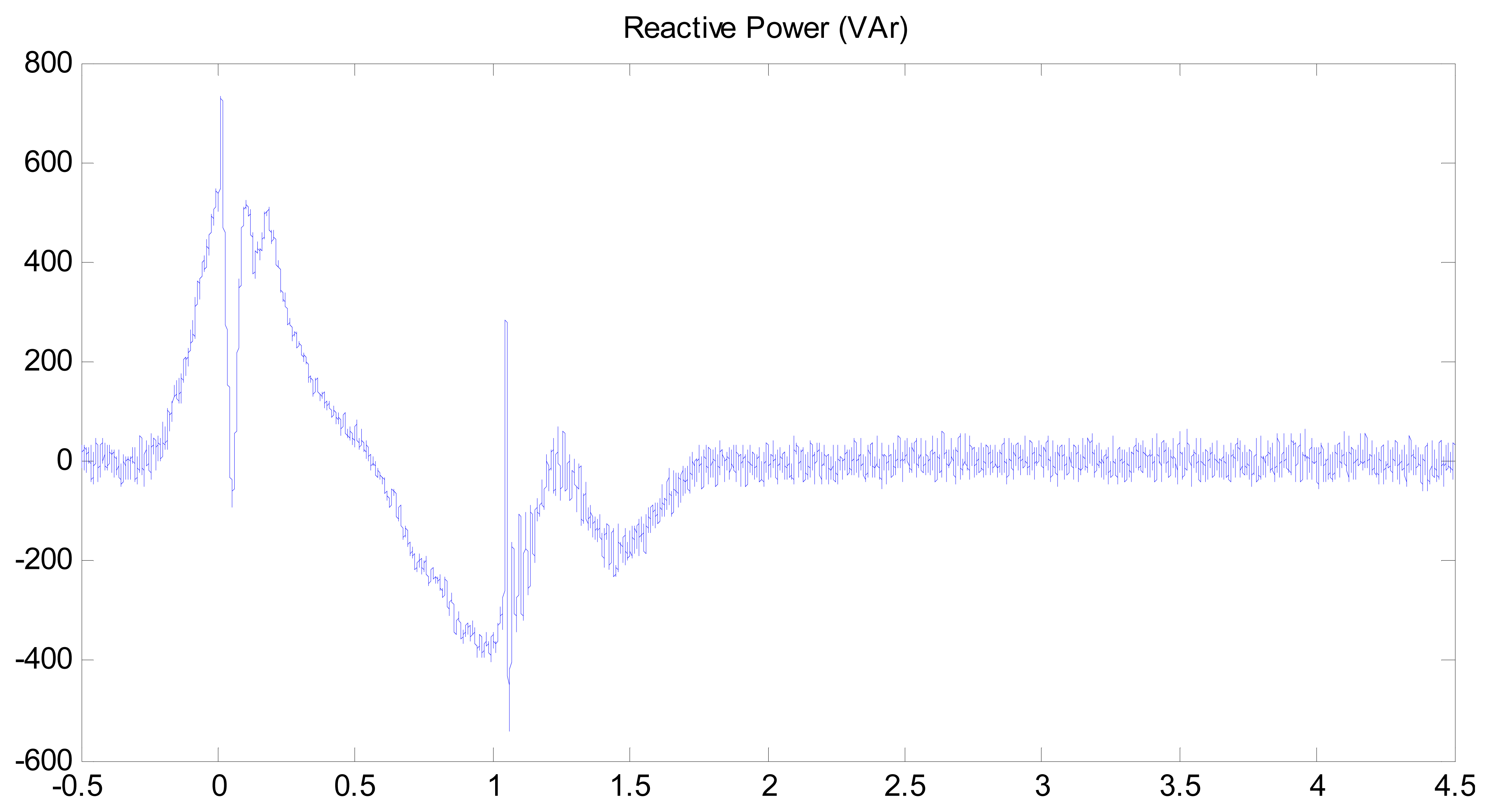
Concerning grid-side converter control, the priority was ensuring that it contributed to the stabilization of the DC voltage, crucial for the correct operation of the IGBT's of both converters. Since this was fulfilled no further modification was made to the grid-side converter control. However, as it can be seen in Figure 19, improvements can be made to the mentioned control. A specific strategy could be implemented in order to stabilize the reactive power that the converter exchanges with the grid. Ideally, its control during voltage sag should induce the converter to deliver reactive power to the grid that will be added to that delivered through the stator.
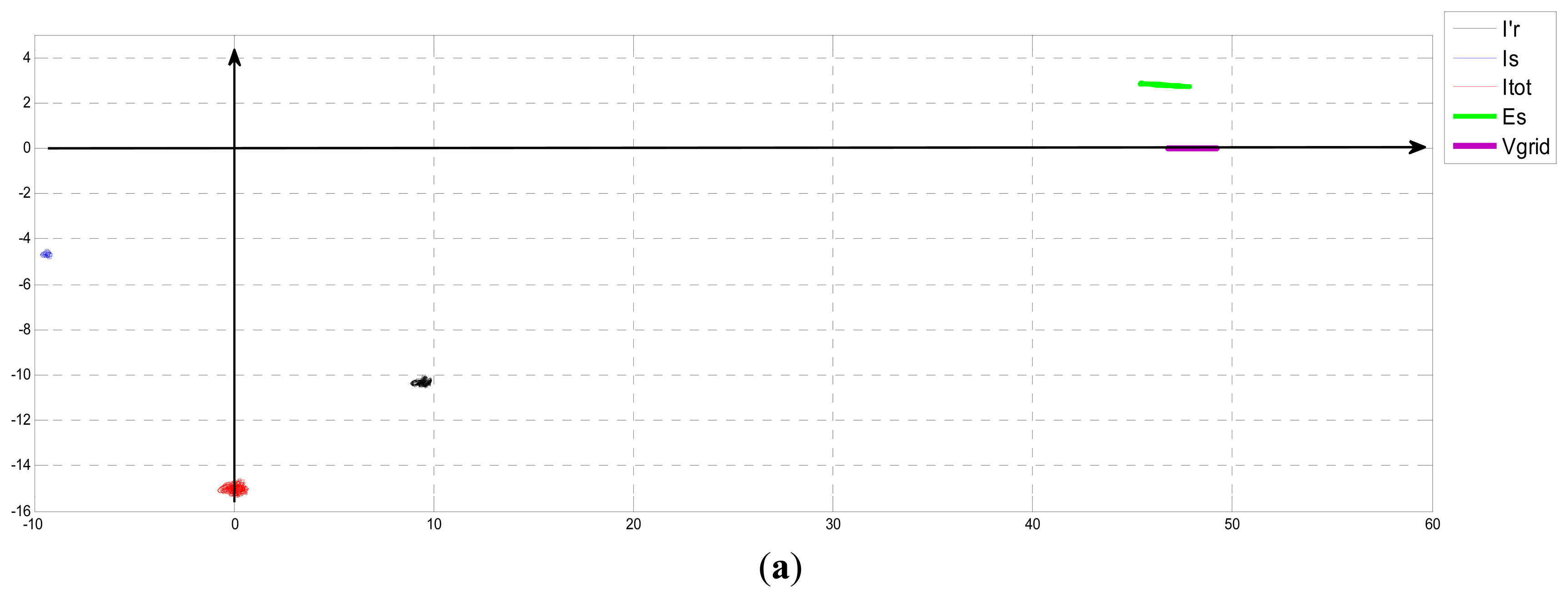
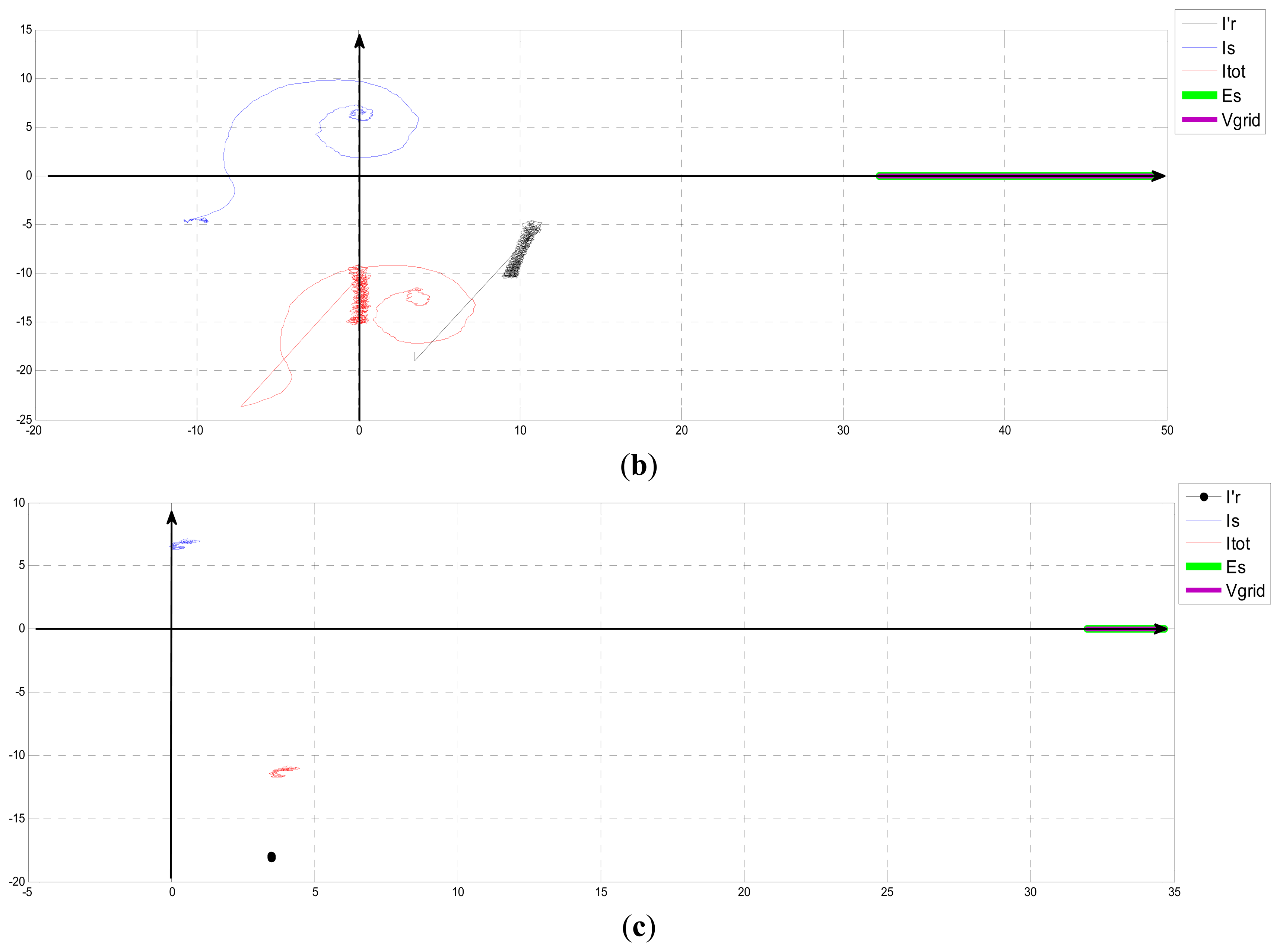
Finally, in Figure 20 the evolution of the current phasors IS, I′r and Itot, during the tested voltage sag has been presented. The top image 20 shows the position of the phasors before the fault (P = 3000 W, Q = −1500 VAr). The middle image shows the evolution during the voltage dip. Note that before the strategy acts, the previous voltage reduction implies a short reduction of the rotor current and total current shown. Finally, the last image shows the position of the vectors during the sag and along the beginning of the grid voltage-restoration phase. It can be seen how this evolution follows the desired pattern shown in Figure 5. The strategy manages stator voltage (green) which follows at all times the evolution of grid voltage (purple) in order to limit the stator currents, reducing to zero the active power delivered to the grid. The stator current (blue) is finally set to a position where maximal reactive power is delivered. It can also be seen how the total machine flux represented by the total machine current (red) is controlled at all times, as well as the rotor currents (black) that are always within acceptable limits.
Regardless of test-bench limitations, Figure 20 proves that it is possible to implement the proposed simple control strategy successfully, without risk to power electronics devices, and to achieve the objective of improving existing systems.
6. Conclusions
This paper has the intention of contributing to the search for a robust and reliable solution that allows DFIG-based wind generating systems to withstand voltage sags while respecting grid code requirements. The sought solution is purely software-based as it is achieved through the modification of the machine's control without the need of additional devices such as crowbars, voltage restorers, etc. Thus, the achievable benefits are the improvement in fulfilling grid code requirements, and the elimination of costly devices that take up space, add weight and increase WTGS maintenance costs.
Two alternatives for rotor current control during the fault are proposed, both based on space-phasor theory. The first one, only in an early stage of development, uses measured stator current to calculate the rotor current needed to create the total flux desired during the sag. The second one, based on the first, consists of imposing a magnetic flux on the machine rotor with a studied magnitude and position. This action ensures an appropriate evolution of the rest of the electric variables that are affected by the transient introduced by the voltage dip. The machine will be governed by this imposed flux and not by other transient magnetic fluxes induced by the grid disturbance. The simple open-loop current control which imposes an I′r phasor during the voltage sag, with a desired amplitude and position that have been previously calculated, assures rotor current limitation during the fault, since its instant value is imposed by the control.
Besides the mandatory simulation studies on a commercial 2 MW DFIG, experiments were carried out on a laboratory test-bench to demonstrate the veracity of the suggested strategy. These types of tests are not often performed due to limited access to DFIG installations. However, a scale laboratory test-bench developed by the ETSII-UPM electric machines laboratory was available for the mentioned experiments. This test-bench genuinely emulates a WTGS behavior, implying that the experimental results prove that the proposed strategy is both valid and physically implementable on a real installation. Although the simulations performed, using the proposed control on a real 2 MW DFIG installation during a standard voltage sag, show acceptable behavior of machine variables, an increase of the DC-bus voltage ratings would imply a better performance of machine LVRT during different types of faults with different maximum current levels specified during the fault.
Acknowledgments
This work was funded by the Spanish Ministry of Education and Science and by the Ministry of Science and Innovation under research grants PN-ENE2005-06299 and PN-ENE2009-13276, respectively.
Conflicts of Interest
The authors declare no conflict of interest.
References
- Veganzones, C.; Martínez, S.; Blázquez, F. Large scale integration of wind energy into power systems. Electr. Power Qual. Util. Mag. 2005, 1, 15–22. [Google Scholar]
- Morren, J.; de Haan, S.W.H. Ridethrough of wind turbines with doubly-fed induction generator during a voltage dip. IEEE Trans. Energy Convers 2005, 20, 435–441. [Google Scholar]
- Hu, J.; He, Y. Reinforced control and operation of DFIG-based wind power-generation system under unbalanced grid voltage conditions. IEEE Trans. Energy Convers 2009, 24, 905–915. [Google Scholar]
- Hu, J.; He, Y. DFIG wind generation systems operating with limited converter rating considered under unbalanced network conditions—Analysis and control design. Renew. Energy 2011, 36, 829–847. [Google Scholar]
- Yan, X.; Venkataramanan, G.; Flannery, P.S.; Wang, Y.; Dong, Q.; Zhang, B. Voltage-sag tolerance of DFIG wind turbine with a series grid side passive-impedance network. IEEE Trans. Energy Convers 2010, 25, 1048–1056. [Google Scholar]
- Yao, J.; Li, Q.; Chen, Z.; Liu, A. Coordinated control of a DFIG-based wind-power generation system with SGSC under distorted grid voltage conditions. Energies 2013, 6, 2541–2561. [Google Scholar]
- Wessels, C.; Gebhardt, F.; Fuchs, F.W. Fault ride-through of a DFIG wind turbine using a dynamic voltage restorer during symmetrical and asymmetrical grid faults. IEEE Trans. Power Electron 2011, 26, 807–815. [Google Scholar]
- Chung, I.-Y.; Won, D.-J.; Park, S.-Y.; Moon, S.-I.; Park, J.-K. The DC link energy control method in dynamic voltage restorer system. Int. J. Electr. Power Energy Syst. 2003, 25, 525–531. [Google Scholar]
- Mareia, M.I.; Eltantawyb, A.B.; El-Sattar, A.A. An energy optimized control scheme for a transformerless DVR. Electr. Power Syst. Res. 2012, 83, 110–118. [Google Scholar]
- Yang, L.; Xu, Z.; Ostergaard, J.; Dong, Z.Y.; Wong, K.P. Advanced control strategy of DFIG wind turbines for power system fault ride through. IEEE Trans. Power Syst. 2011, 27, 713–722. [Google Scholar]
- Liang, J.; Qiao, W.; Harley, R.G. Feed-forward transient current control for low-voltage ride-through enhancement of DFIG wind turbines. IEEE Trans. Energy Convers 2010, 25, 836–843. [Google Scholar]
- Wu, Z.; Zhu, C.; Hu, M. Improved control strategy for DFIG wind turbines for low voltage ride through. Energies 2013, 6, 1181–1197. [Google Scholar]
- Rahimi, M.; Parniani, M. Coordinated control approaches for low-voltage ride-through enhancement in wind turbines with doubly fed induction generators. IEEE Trans. Energy Convers 2010, 25, 873–883. [Google Scholar]
- Lima, F.K.A.; Luna, A.; Rodriguez, P.; Watanabe, E.H.; Blaabjerg, F. Rotor voltage dynamics in the doubly fed induction generator during grid faults. IEEE Trans. Power Electron 2010, 25, 118–130. [Google Scholar]
- Rolán, A.; Córcoles, F.; Pedra, J. Doubly fed induction generator subject to symmetrical voltage sags. IEEE Trans. Energy Convers 2011, 26, 1219–1229. [Google Scholar]
- Flores Mendes, V.; de Sousa, C.V.; Rocha Silva, S.; Cezar Rabelo, B.; Hofmann, W. Modeling and ride-through control of doubly fed induction generators during symmetrical voltage sags. IEEE Trans. Energy Convers 2011, 26, 1161–1171. [Google Scholar]
- Arribas, J.R.; Veganzones, C.; Blázquez, F.; Platero, C.; Ramírez, D.; Martínez, S.; Sánchez, J.A.; Herrero, N. Computer-based simulation and scaled laboratory bench system for the teaching and training of engineers on the control of doubly fed induction wind generators. IEEE Trans. Power Syst. 2011, 26, 1534–1543. [Google Scholar]
- REE Procedimiento de Operación P.O. 12.3 Requisitos de Respuesta Frente a Huecos de Tensión de las Instalaciones Eólicas (in Spanish). Available online: http://www.ree.es/sites/default/files/01_ACTIVIDADES/Documentos/ProcedimientosOperacion/PO_resol_12.3_Respuesta_huecos_eolica.pdf (accessed on 10 December 2013).
- Semikron SKM 800GA126D Power IGBT Data Sheet. Available online: http://www.semikron.com/products/data/cur./SKM800GA126D_22890405.pdf (accessed on 10 December 2013).


| Parameter | Value | Parameter | Value |
|---|---|---|---|
| Us | 690 V | Is | 1510 A |
| Ur | 1826 V | Ir | 580 A |
| PN | 1.8 + 0.2 MW | nN | 1680 r.p.m |
| RS | 0.0069 pu | XσS | 0.0882 pu |
| Rr | 0.0197 pu | Xσr | 0.0924 pu |
| Xμ | 3.4656 pu | JTOT | 2735.7 kg·m2 |
| Parameter | Value | Parameter | Value |
|---|---|---|---|
| Us | 400 V | Is | 13.3 A |
| Ur | 182 V | Ir | 21 A |
| PN | 5.5 kW | nN | 965 r.p.m |
| RS | 0.646 Ω | XσS | 2.701 Ω |
| Rr | 1.208 Ω | Xσr | 2.701 Ω |
| Xμ | 28.63 Ω | JTOT | 0.16 kg·m2 |
© 2014 by the authors; licensee MDPI, Basel, Switzerland. This article is an open access article distributed under the terms and conditions of the Creative Commons Attribution license ( http://creativecommons.org/licenses/by/3.0/).
Share and Cite
Arribas, J.R.; Rodríguez, A.F.; Muñoz, Á.H.; Nicolás, C.V. Low Voltage Ride-through in DFIG Wind Generators by Controlling the Rotor Current without Crowbars. Energies 2014, 7, 498-519. https://doi.org/10.3390/en7020498
Arribas JR, Rodríguez AF, Muñoz ÁH, Nicolás CV. Low Voltage Ride-through in DFIG Wind Generators by Controlling the Rotor Current without Crowbars. Energies. 2014; 7(2):498-519. https://doi.org/10.3390/en7020498
Chicago/Turabian StyleArribas, Jaime Rodríguez, Adrián Fernández Rodríguez, Ángel Hermoso Muñoz, and Carlos Veganzones Nicolás. 2014. "Low Voltage Ride-through in DFIG Wind Generators by Controlling the Rotor Current without Crowbars" Energies 7, no. 2: 498-519. https://doi.org/10.3390/en7020498