Abstract
Solid oxide fuel cells (SOFCs) with proton conducting electrolyte (H-SOFCs) are promising power sources for stationary applications. Compared with other types of fuel cells, one distinct feature of SOFC is their fuel flexibility. In this study, a 2D model is developed to investigate the transport and reaction in an H-SOFC fueled with syngas, which can be produced from conventional natural gas or renewable biomass. The model fully considers the fluid flow, mass transfer, heat transfer and reactions in the H-SOFC. Parametric studies are conducted to examine the physical and chemical processes in H-SOFC with a focus on how the operating parameters affect the H-SOFC performance. It is found that the presence of CO dilutes the concentration of H2, thus decreasing the H-SOFC performance. With typical syngas fuel, adding H2O cannot enhance the performance of the H-SOFC, although water gas shift reaction can facilitate H2 production.
1. Introduction
Solid oxide fuel cells (SOFCs) are promising electrochemical energy conversion devices due to their high efficiency, low pollution, fuel flexibility, and potential for co-generation or multi-generation [1]. To realize commercial SOFC applications, it is very important to further reduce their cost and improve their long-term stability. One effective way is to lower the very high operating temperature from about 1273 K to an intermediate range (873–1073 K). This is because lower cost interconnecting materials can be used at a reduced temperature [2]. In addition, the coarsening of porous electrodes can be greatly slowed down with decreasing temperature, which in turn enhances long-term durability. However, the SOFC performance decreases with decreasing temperature, partly due to the increased Ohm’s loss at the electrolyte. The ohmic loss at the electrolyte can be reduced by fabricating a thin film electrolyte. Large-scale fabrication of SOFCs requires a conventional ceramic processing method (i.e., tape casting), which limits the electrolyte thickness to about 10 µm [3]. Alternatively, the ohmic loss can be decreased by developing new materials with high ionic conductivities. Proton-conducting ceramics have been recognized as a promising electrolyte material for SOFCs operating at reduced temperature due to their good ionic conductivities at a temperature range of 873–1073 K [4]. Experimental studies have demonstrated good performance of SOFCs based on proton-conducting electrolytes (H-SOFCs). Several mathematical models have also been developed to understand the transport and reaction in H-SOFCs [5,6,7]. However, the majority of the models only consider H2 or NH3 as fuel in the H-SOFC [5,6,7,8]. The use of hydrocarbon fuels or syngas has been rarely studied. As the fuel flexibility is a distinct feature of SOFC, it is very important to examine how a H-SOFC performs with alternative fuels.
In the near term, both conventional coal and renewable biomass will be important energy sources. These fuels can be converted to syngas containing H2 and CO, which can be subsequently used in SOFCs for power generation [9,10,11]. Considering the importance of syngas for power generation in SOFCs, this study is purposely designed to investigate the syngas fueled H-SOFC.
2. Model Development
The working principles of a syngas fueled H-SOFC and the computational domain are shown in Figure 1. The computational domain includes interconnect, air channel, porous cathode, dense proton-conducting electrolyte, porous anode, and fuel channel. In operation, syngas (a mixture of H2 and CO) is supplied to the fuel channel while air is supplied to the air channel. When H2O is included in the fuel stream, the water gas shift reaction (WGSR, Equation (1)) will occur in the porous anode, generating CO2 and H2:
CO + H2O ↔ CO2 + H2
H2 molecules diffuse through the porous anode to the triple-phase boundary (TPB) at the anode-electrolyte interface, where they are split into protons and electrons (Equation (2)). The protons are transported through the dense electrolyte to the cathode. The electrons are transported via the electronic network of the porous anode to the anode surface, where they are collected by the current collector (interconnect). Subsequently, electrons flow through the external circuit to the cathode side, where they react with oxygen molecules and protons to produce steam (Equation (3)).
H2 → 2H+ + 2e−
2H+ + 0.5O2 + 2e− → H2O
Both the electrochemical reactions and WGSR are exothermic. The overpotential loss in SOFC also contributes to heat generation. Thus, the H-SOFC fueled with syngas involves heat transfer, fluid flow, mass transfer, chemical reaction (if H2O is included), and electrochemical reactions. A numerical model is developed to simulate all these processes. The model consists of three sub-models: (1) an electrochemical model for determining the electrochemical reaction rates and related heat generation; (2) a chemical model for calculating the rate of WGSR if H2O is included in the fuel stream; and (3) a computational fluid dynamics (CFD) model for simulating the fluid flow, heat transfer and mass transfer in the cell.
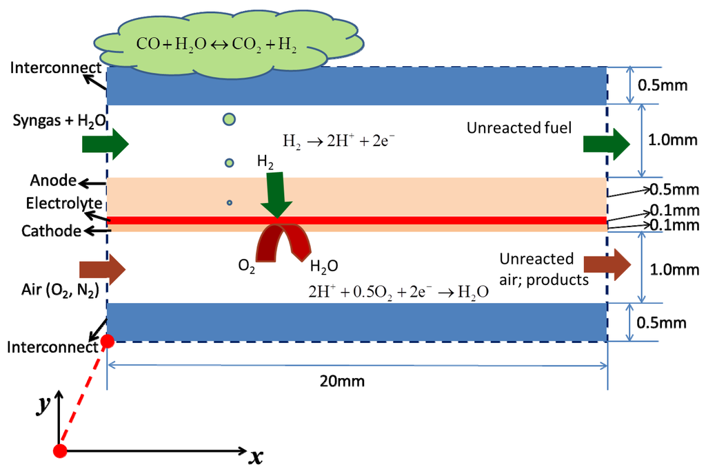
Figure 1.
Working principle of syngas fueled H-SOFC and the computational domain.
The following assumptions are adopted in the model:
- (1)
- The model is 2D, neglecting the 3D effect;
- (2)
- Heat radiation is assumed to be negligible;
- (3)
- The flow in the gas channels is laminar due to low velocity and small dimension;
- (4)
- Electrochemical reactions are assumed to take place at the electrode-electrolyte interface only.
2.1. Electrochemical Model
In the H-SOFC, only H2 can participate in the electrochemical reaction to produce protons and electrons. Electrochemical oxidation of CO can occur in a SOFC with an oxygen ion conducting electrolyte (O-SOFC), but cannot occur in H-SOFC due to the lack of oxygen ions at the anode.
In a SOFC, the electrical conductivity of interconnect is usually quite high and thus the electrical potential along the flow channel can be considered as uniform. The operating potential (V) can be determined as [12]:
 where E is the equilibrium potential and the subscripts; T is temperature (K). R is the universal gas constant (8.3145 J·mol−1·K−1). F is the Faraday constant (96,485 C·mol−1).
  is the partial pressure of H2 at the anode-electrolyte interface.
  and
and  are the partial pressure of O2 and H2O at the cathode-electrolyte interface, respectively. Thus, the concentration overpotentials at the electrodes are included in the Nernst potential (Equation (5)). ηohmic is the ohmic overpotential of the electrolyte and can be determined as:
 where L is the thickness (m) of the electrolyte and σionic is the ionic conductivity (Ω−1·m−1). J is the current density (A·m−2). According to Matsumoto [13], the proton conductivity of the BaCe0.8Y0.2O3-α electrolyte is about 2.6 S·m−1 at 973 K and 3.5 S·m−1 at 1073 K. Thus, the proton conductivity (σionic, S·m−1) can be approximated as:
ηact,a and ηact,c are the activation overpotentials with the subscript a and c referring to the anode and cathode, respectively. As experimental studies suggests linear relationship between current density and the activation overpotential [14], ηact can be determined as:
 where
where  is the exchange current densities (A·m−2) which indicates the activity of the electrode. n is the number of electrons involved in the electrochemical reaction. Based on the previous studies, the exchange current densities for anode and cathode are 5300 A·m−2 and 2000 A·m−2, respectively [15].
V = E − ηact,a − ηact,c − ηohmic

 is the partial pressure of H2 at the anode-electrolyte interface.
  and
and  are the partial pressure of O2 and H2O at the cathode-electrolyte interface, respectively. Thus, the concentration overpotentials at the electrodes are included in the Nernst potential (Equation (5)). ηohmic is the ohmic overpotential of the electrolyte and can be determined as:

σionic = 0.009T − 6.157

 is the exchange current densities (A·m−2) which indicates the activity of the electrode. n is the number of electrons involved in the electrochemical reaction. Based on the previous studies, the exchange current densities for anode and cathode are 5300 A·m−2 and 2000 A·m−2, respectively [15].
2.2. Chemical Model
The reaction rate and reaction heat of WGSR are calculated in the chemical model. The reaction rate for WGSR (RWGSR, mol·m−3·s−1) can be calculated with the Haberman and Young formula [16]:


Kps = exp(−0.2935Z3 + 0.6351Z2 + 4.1788Z + 0.3169)

The heat generation from the exothermic WGSR (HWGSR, J·mol−1) can be approximated using the enthalpy change of the WGSR reaction as [17]:
HWGSR = 45063 − 10.28T
2.3. Computational Fluid Dynamic (CFD) Model
The laminar fluid flow, heat and mass transfer processes are modeled with the CFD model. The local thermal equilibrium is adopted assuming a negligible temperature difference between the solid structure and the gas stream in the porous electrodes [18]. The governing equations in the CFD model are summarized below [19]:


U and V are the velocity in x and y directions, respectively. ρ is the effective density of gas mixture and can be determined as:
 where ρi and Yi are the density and mass fraction of gas species i.

The effective viscosity of the gas mixture (µ) can be calculated as [20]:

 where Mi is molecular weight of species i (kg·kmol−1).


In the porous anode and cathode, the effective heat conductivity (k) and the effective heat capacity (cp) can be calculated as [21]:
k = εkf + (1 − ε) ks
cp = εcp,f + (1 − ε) cp,s
In the gas channel, the effective diffusion coefficient  only includes the molecular diffusion while both molecular diffusion and Knudsen diffusion are considered in the porous electrodes. The value of
  can thus be calculated as [20]:
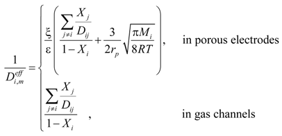

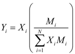
 where ξ/ε is the ratio of tortuosity to porosity of the electrodes. rp is the average radius of pores; Dij is the binary/molecular diffusion coefficient; σ is the mean characteristic length of species; ΩD is a dimensionless diffusion collision term; kb is the Boltzmann’s constant (1.38066 × 10⁻²³ J·K−1). The values of σi and εij are summarized in Table 1 [20]. Xi is the molar fraction of specie i. The mass fraction (Yi) can be converted from the molar fraction as:
 only includes the molecular diffusion while both molecular diffusion and Knudsen diffusion are considered in the porous electrodes. The value of
  can thus be calculated as [20]:


Table 1.
Values of σi and εi/k for calculating the diffusion coefficients [20].
| CO | CO2 | H2 | O2 | N2 | H2O | |
|---|---|---|---|---|---|---|
| σi (A) | 3.69 | 3.941 | 2.827 | 3.467 | 3.798 | 2.641 |
| εi/k (K2·J−1) | 91.7 | 195.2 | 59.7 | 106.7 | 71.4 | 809.1 |
In the momentum equation, Darcy’s law is used as source terms so that the momentum equations can be applied to both gas channels and the porous electrodes:

 where Bg is the permeability (m2). Typical value of Bg of 2 × 10⁻¹⁰ m2 is used for the SOFC porous electrodes while 1020 m2 is used for the gas channels.


The source term (ST, W·m−3) in the energy equation (Equation (17)) represents the heat generation from the WGSR reaction, electrochemical reactions, and irreversible overpotential losses. Thus, the source term ST can be written as [12]:
 where ∆S is the entropy change for electrochemical reaction. ηt is the total overpotential loss.

The source term (Ssp, kg·m−3·s−1) in the species equation (Equation (18)) is caused by the chemical and electrochemical reactions. For H2, the source term (SH2) can be written as:
 where ∆y is the control volume width in y-direction (Figure 1) at the anode-electrolyte interface.

3. Numerical Methodologies
The finite volume method (FVM) is adopted to discretize and solve the governing equations presented in the previous sections. The central difference and upwind schemes are used to treat the diffusive and convective terms. The SIMPLEC algorithm is used to link the pressure and the velocity. The algebraic equations are solved iteratively. The details on the boundary conditions can be found from our previous publications [22]. The program starts from initialization—initial velocity field, temperature field, and gas composition are specified over the whole computational domain. Then the electrochemical model is solved to calculate the current density along the flow channel. Subsequently, the chemical model is solved to determine the rate of WGSR. Based on the electrochemical model and chemical model, the source terms for CFD model can be determined. After the CFD model is solved, the flow field, temperature field, the pressure field, and the gas composition in the cell can be updated. Computation is repeated using the updated data, until convergence is achieved. The program is written in FORTRAN and has been validated. Details on the validation of the model can be found in the previous publications [22] and not reported here.
4. Results and Analysis
In this section, simulations are performed to investigate the effect of various operating parameters on the performance of the syngas fueled H-SOFC. The values of model parameters are summarized in Table 2. As the cell in the simulation is short, both the fuel utilization and energy efficiency are expected to be low [23]. The practical consideration of the gas recycling is also not considered as the focus of the study is on the fundamental processes occurring in the cell.

Table 2.
Parameters used in simulation.
| Parameter | Value |
|---|---|
| Operating temperature, T (K) | 1073 |
| Operating pressure, P (bar) | 1.0 |
| Electrode porosity, ε | 0.4 |
| Electrode tortuosity, ξ | 3.0 |
| Average pore radius, rp (μm) | 0.5 |
| Anode-supported electrolyte: | - |
| Anode thickness da (μm) | 500 |
| Electrolyte thickness, L (μm) | 100 |
| Cathode thickness, dc (μm) | 100 |
| Height of gas flow channel (mm) | 1.0 |
| Length of the planar SOFC (mm) | 40 |
| Thickness of interconnector (mm) | 0.5 |
| Inlet velocity at anode: U0 (m·s−1) | 1.0 |
| Cathode inlet gas molar ratio: O2/N2/ | 0.18/0.79/0.03 |
| Anode inlet gas molar ratio: H2/CO (Syngas) | 3/1 |
| SOFC operating potential (V) | 0.7 |
| Thermal conductivity of SOFC component (W·m−1·K−1) | - |
| Anode | 11.0 |
| Electrolyte | 2.7 |
| Cathode | 6.0 |
| Interconnect | 1.1 |
4.1. Effect of Syngas Composition
In practice, CH4 can be steam reformed to produce syngas with a H2/CO molar fraction ratio of 3/1 (Equation (32)). Alternatively, CO2 reforming of CH4 can produce a gas mixture of 50% H2 and 50% CO (Equation (33)):
CH4 + H2O ↔ CO + 3H2
CH4 + CO2 ↔ 2CO2 + 2H2
Thus, the molar fraction ratio of H2/CO can range from 1/1 to 3/1. In this section, the local current density in syngas fueled H-SOFC is shown in Figure 2a. As can be seen, the local current density increases considerably with an increase in molar fraction of H2. This is because only H2 is involved in the electrochemical reaction thus the existence of CO only dilutes the concentration of H2, which in turn decreases the Nernst potential of the cell (Figure 2b).
To better understand the coupled transport and reaction in the SOFC, the gas composition, temperature and velocity ratio (U/U0) are studied. As can be seen from Figure 3a,c, the molar fractions of H2 and O2 decrease along the channel as the electrochemical reactions consume the fuel and oxidant. The variation in O2 molar fraction is smaller than that of H2, as the flow rate in the cathode is three times that of the anode. For comparison, the CO molar fraction is slightly increased (Figure 3b). As CO is not involved in electrochemical reaction, its total amount is unchanged but its molar fraction is increased due to decreased amount of H2 in the anode. This is different from O-SOFC, in which both H2 and CO are electrochemically consumed in the anode [12]. Due to the heat generation from the electrochemical reactions and the overpotential losses, the temperature in the SOFC is found to increase considerably along the channel (Figure 4). In the present simulation, the temperature at the outlet of the SOFC is about 45 K higher than that at the inlet, indicating an average temperature gradient of about 11 K/cm along the channel. The velocity contours in the anode and cathode are plotted in Figure 5. As can be seen, the velocity profiles in SOFC channels are similar to conventional fully developed duct flows. The velocity in the porous electrodes is very low, indicating the mass transport is mainly by means of diffusion.
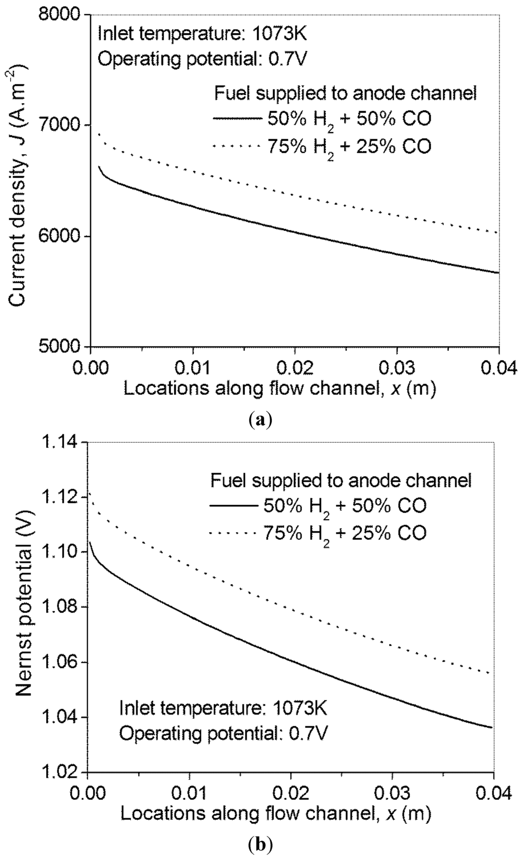
Figure 2.
Effect of syngas composition on the performance of H-SOFC—(a) current density distribution; (b) Nernst potential distribution.
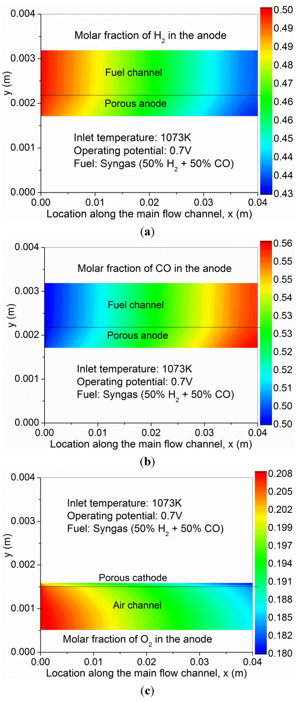
Figure 3.
Gas composition in syngas fueled SOFC—(a) H2; (b) CO; and (c) O2.
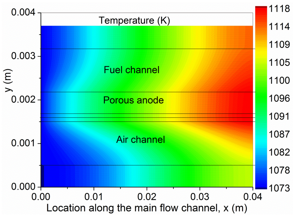
Figure 4.
Temperature in SOFC.
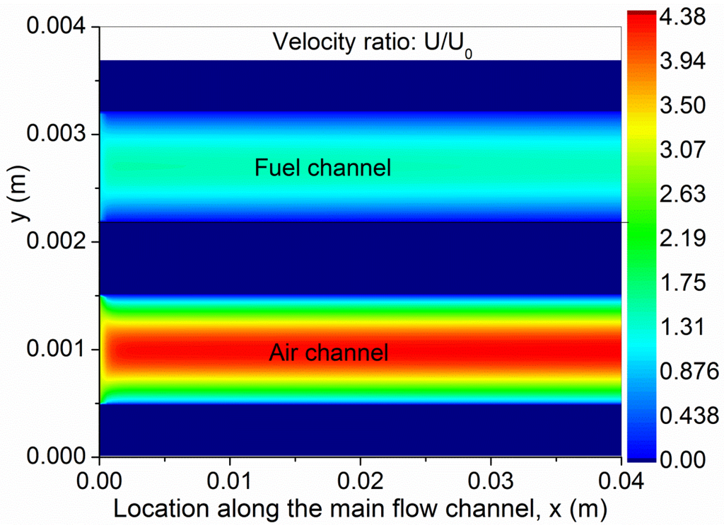
Figure 5.
Velocity contours in H-SOFC.
4.2. Effect of Operating Temperature
For a SOFC, temperature is a critical parameter affecting the performance, durability and cost. As there is a trend to lower the operating temperature down to an intermediate level, the inlet temperature is purposely decreased to 973 K in the present study. As can be seen from Figure 6a, a reduction in temperature considerably decreases the current density of H-SOFC. This is because the total overpotential loss increases with decreasing temperature, although the Nernst potential increases (Figure 6b).
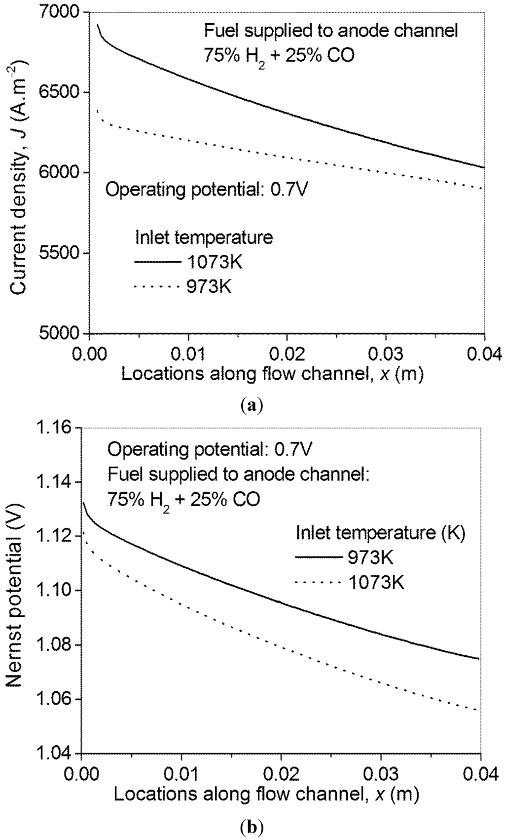
Figure 6.
Effect of inlet temperature on H-SOFC performance—(a) local current density; and (b) local Nernst potential.
4.3. Effect of Steam Addition
Since the existence of CO in H-SOFC decreases the cell performance, steam is purposely included in the fuel stream to initiate the WGSR reaction with an aim to produce more H2. Simulations are performed for fuel stream with varied steam addition. As can be seen from Figure 7, addition of steam does not enhance the electrical performance of the H-SOFC.
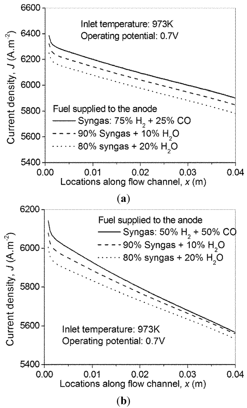
Figure 7.
Effect of steam addition on performance of syngas fueled H-SOFC—(a) syngas with H2/CO molar ratio of 3/1; and (b) syngas with H2/CO molar ration of 1/1.
This is because addition of steam tends to dilute the H2 concentration on the one hand, and tends to increase H2 concentration via the WGSR on the other hand. In the present simulations, the decreased current density with H2O addition indicates that the dilution effect dominates. This is because the H2 molar fraction in the syngas is high (no less than 50%) while the molar fraction of CO is relatively low. Thus the H2 generated from the WGSR is insufficient to offset the dilution effect. However, it is expected that with increasing CO concentration, the addition of steam will become necessary. For example, if pure CO is supplied to the bH-SOFC, the power output without H2O addition is 0, thus H2O is needed to produce H2 for power generation.
5. Conclusions
A 2D numerical model is developed for a syngas fueled H-SOFC. The model considers the fluid flow, heat transfer, mass transfer, as well as reactions in the H-SOFC. Parametric simulations are performed to investigate the effect of operating parameters on H-SOFC performance. With typical syngas fuel, the CO dilutes the H2 concentration and decreases the performance of the H-SOFC. The electrical output of the H-SOFC is increased with increasing temperature, although the Nernst potential is decreased. Adding H2O to the syngas fuel facilitates H2 generation from WGSR. However, it decreases the H-SOFC performance as the dilution effect dominates.
Acknowledgments
This research is supported by a fund from The Research Grant Council (RGC) of Hong Kong (Project No: PolyU 5326/12E).
Author Contributions
Meng Ni contributed to the model development and simulation. Zongping Shao and Kwong Yu Chan contributed to analysis and paper revision.
Nomenclature
| Bg | Permeability of the porous electrode (m2) |
| cp | Heat capactity (J·kg−1·K−1) |
| da | Thickness of anode (µm) |
| dc | Thickness of cathode (µm) |
 | Effective diffusion coefficient of species i in gas mixture (cm2·s−1) |
| Di,k | Knudsen diffusion coefficient of i (cm2·s−1) |
| Di,j | Binary diffusion coefficient of i and j (cm2·s−1) |
| E | Equilibrium potential (V) |
| E0 | Reversible potential at standard condition (V) |
| F | Faraday constant (9.6485 × 10⁴ C·mol−1) |
| HWGS | Heat generation from water gas shift reaction (J·mol−1) |
| J | Current density (A·m−2) |
| k | Thermal conductivity (W·m−1·K−1) |
| L | Thickness of the electrolyte (m) |
| Mi | Molecular weight of species i (kg·mol-1) |
| n | Number of electrons transferred |
| P | Operating pressure (bar) |
 | Partial pressure (bar) of species i at electrode-electrolyte interface |
| RWGSR | Rate of water gas shift reaction (mol·m−3·s−1) |
| rp | Mean pore radius of electrode (µm) |
| R | Universal gas constant (8.3145 J·mol−1·K−1) |
| ∆S | Entropy change of electrochitalicical reactions (kJ·kg−1·K−1) |
| Sm | Source term in continuity equation (kg·m−3·s−1) |
| Sx, Sy | Source terms in momentum equations (kg·m−2·s−2) |
| ST | Source terms in energy equations (W·m−3) |
| Ssp | Source terms in species equations (kg·m−3·s−1) |
| T | Operating titalicperature (K) |
| U | Velocity in x direction (m·s−1) |
| U0 | Gas velocity at the SOFC inlet (m·s−1) |
| V | SOFC operating potential (V); Velocity in y direction (m·s−1) |
| X | Molar fraction of species i |
| Y | Mass fraction of species i |
| ε | Electrode porosity |
| ξ | Electrode tortuosity |
| σi,j | Mean characteristic length of species i and j (Å) |
| σionic | Ionic conductivity of the electrolyte (Ω−1·m−1) |
| ΩD | Dimensionless diffusion collision integral |
| ρ | Density of the gas mixture (kg·m−3) |
| µ | Viscosity of gas mixture (kg·m−1·s−1) |
| ηact,a | Activation overpotential at anode (V) |
| ηact,c | Activation overpotential at cathode (V) |
| ηohmic | Ohmic overpotential of the electrolyte (V) |
Conflicts of Interest
The authors declare no conflicts of interest.
References
- Wachsman, E.D.; Lee, K.T. Lowering the temperature of solid oxide fuel cells. Science 2011, 334, 935–939. [Google Scholar] [CrossRef]
- Lee, K.T.; Yoon, H.S.; Wachsman, E.D. The evolution of low temperature solid oxide fuel cells. J. Mater. Res. 2012, 27, 2063–2078. [Google Scholar] [CrossRef]
- Wang, Z.R.; Qian, J.; Cao, J.; Wang, S.R.; Wen, T.L. A study of multilayer tape casting method for anode-supported planar type solid oxide fuel cells (SOFCs). J. Alloys Compd. 2007, 437, 264–268. [Google Scholar] [CrossRef]
- Iwahara, H. High temperature protonic conductors and their applications. Solid State Ion. 1992, 575–586. [Google Scholar]
- Liu, H.; Akhtar, Z.; Li, P.W.; Wang, K. Mathematical modeling analysis and optimization of key design parameters of proton-conductive solid oxide fuel cells. Energies 2014, 7, 173–190. [Google Scholar] [CrossRef]
- Ni, M.; Leung, D.Y.C.; Leung, M.K.H. An improved electrochemical model for the NH3 fed proton conducting solid oxide fuel cells at intermediate temperatures. J. Power Sources 2008, 185, 233–240. [Google Scholar] [CrossRef]
- Ni, M.; Leung, M.K.H.; Leung, D.Y.C. Mathematical modeling of proton-conducting solid oxide fuel cells and comparison with oxygen ion conducting counterpart. Fuel Cells 2007, 7, 269–278. [Google Scholar] [CrossRef]
- Ni, M. The effect of electrolyte type on performance of solid oxide fuel cells running on hydrocarbon fuels. Int. J. Hydrog. Energy 2013, 38, 2846–2858. [Google Scholar] [CrossRef]
- Andersson, M.; Yuan, J.L.; Sunden, B. SOFC modeling considering hydrogen and carbon monoxide as electrochemical reactants. J. Power Sources 2013, 232, 42–54. [Google Scholar] [CrossRef]
- Pieratti, E.; Baratieri, M.; Ceschini, S.; Tognana, L.; Baggio, P. Syngas suitability for solid oxide fuel cells applications produced via biomass steam gasification process: Experimental and modeling analysis. J. Power Sources 2011, 196, 10038–10049. [Google Scholar] [CrossRef]
- Lorente, E.; Millan, M.; Brandon, N.P. Use of gasification syngas in SOFC: Impact of real tar on anode materials. Int. J. Hydrog. Energy 2012, 37, 7271–7281. [Google Scholar] [CrossRef]
- Ni, M. Modeling of SOFC running on partially pre-reformed gas mixture. Int. J. Hydrog. Energy 2012, 37, 1731–1745. [Google Scholar] [CrossRef]
- Matsumoto, H. Proton-conducting Perovskite—Properties and Experiences for Hydrogen Transport and Energy Applications. In Proceedings of the Prospects Protonic Ceramic Cells 2011—International Workshop on Protonic Ceramic Fuel Cell and Steam Electrolysis: Status and Prospects, Botanical Institute, Montpellier, France, 3–4 November 2011.
- Sohal, M.S.; Idaho National Laboratory, Idaho Falls, ID, USA. Personal communication at ASME 2010 8th International Fuel Cell Science, Engineering & Technology Conference, Brooklyn, NY, USA, 14–16 June 2010.
- Ni, M.; Leung, M.K.H.; Leung, D.Y.C. Parametric study of solid oxide fuel cell performance. Energy Convers. Manag. 2007, 48, 1525–1535. [Google Scholar] [CrossRef]
- Haberman, B.A.; Young, J.B. Three-dimensional simulation of chemically reacting gas flows in the porous support structure of an integrated-planar solid oxide fuel cell. Int. J. Heat Mass Transf. 2004, 47, 3617–3629. [Google Scholar] [CrossRef]
- Chase, M.W. NIST-JANAF Thermochemical Tables, 4th ed.; American Chemical Society, American Institute of Physics for the National Institute of Standards and Technology: Washington, DC, USA, 1998. [Google Scholar]
- Zheng, K.Q.; Sun, Q.; Ni, M. On the local thermal non-equilibrium in SOFCs considering internal reforming and ammonia thermal cracking reaction. Energy Technol. 2013, 1, 35–41. [Google Scholar] [CrossRef]
- Wang, C.Y. Fundamental models for fuel cell engineering. Chem. Rev. 2004, 104, 4727–4765. [Google Scholar] [CrossRef]
- Reid, R.C.; Prausnitz, J.M.; Poling, B.E. The Properties of Gases & Liquids, 4th ed.; McGraw-Hill Book Company: New York, NY, USA, 1987. [Google Scholar]
- Yuan, J.L.; Lv, X.R.; Sunden, B.; Yue, D.T. Analysis of parameter effects on transport phenomena in conjunction with chemical reactions in ducts relevant for methane reformers. Int. J. Hydrog. Energy 2007, 32, 3887–3898. [Google Scholar] [CrossRef]
- Ni, M. 2D thermal-fluid modeling and parametric analysis of a planar solid oxide fuel cell. Energy Convers. Manag. 2010, 51, 714–721. [Google Scholar] [CrossRef]
- Ni, M. Thermo-electrochemical modeling of ammonia-fueled solid oxide fuel cells considering ammonia thermal decomposition in the anode. Int. J. Hydrog. Energy 2011, 36, 3153–3166. [Google Scholar] [CrossRef]
© 2014 by the authors; licensee MDPI, Basel, Switzerland. This article is an open access article distributed under the terms and conditions of the Creative Commons Attribution license (http://creativecommons.org/licenses/by/3.0/).