An Adaptive Gain Nonlinear Observer for State of Charge Estimation of Lithium-Ion Batteries in Electric Vehicles

Abstract
:1. Introduction
2. Battery Modeling
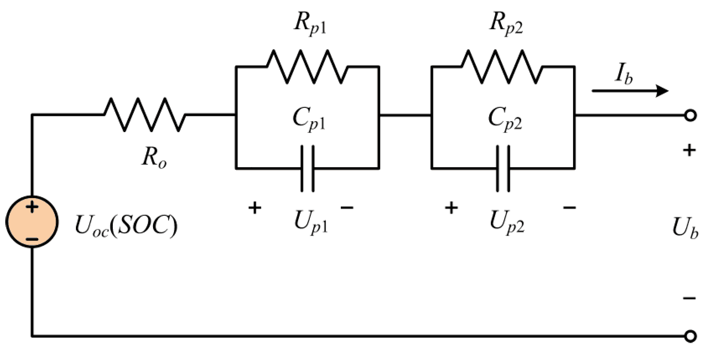
2.1. Battery Equivalent Circuit Model

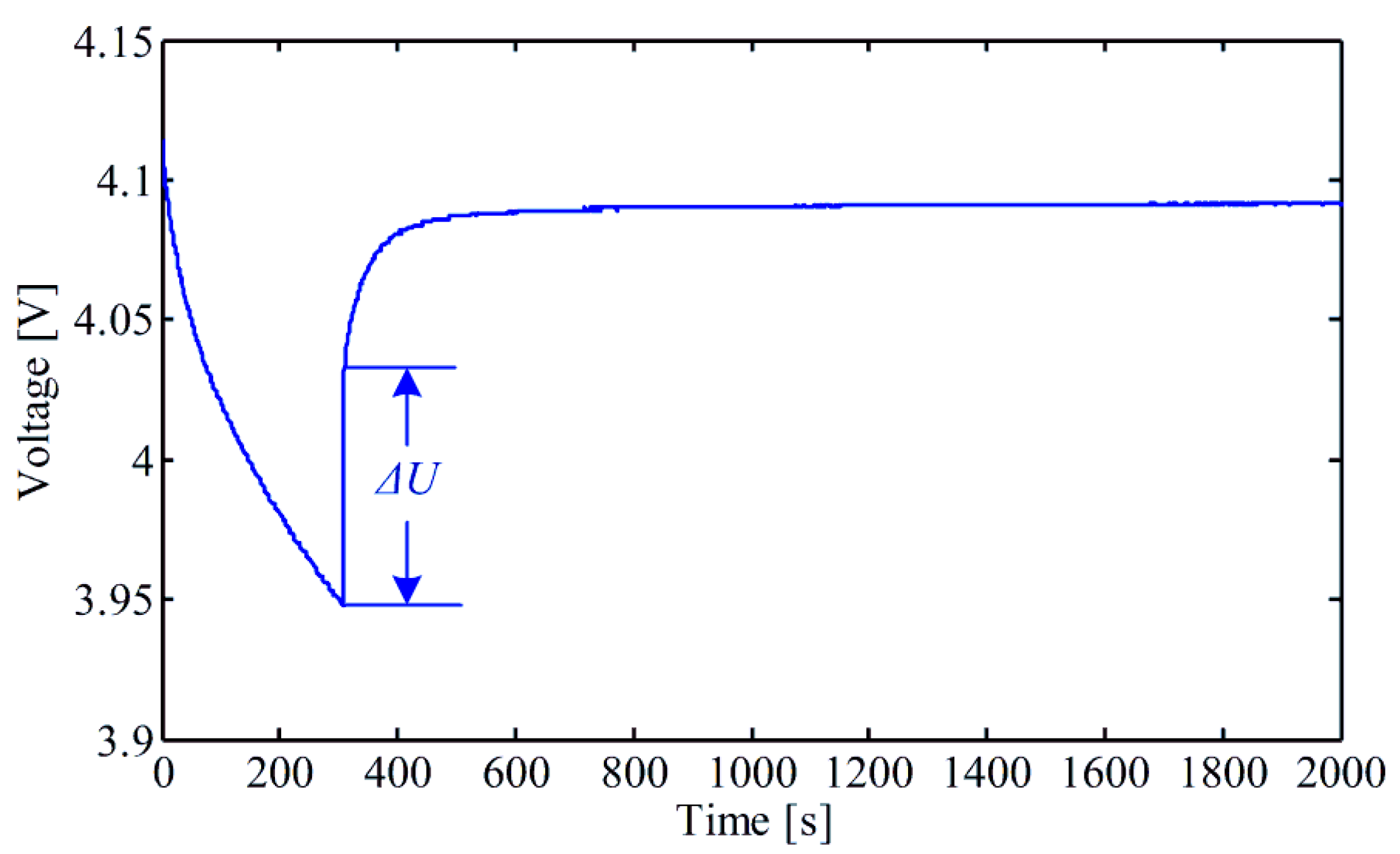
2.2. Model Parameters Determination


3. Design of Adaptive Gain Nonlinear Observer for State of Charge Estimation
4. Experimental Results and Discussion
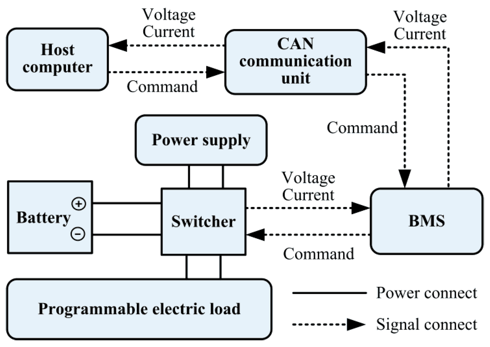
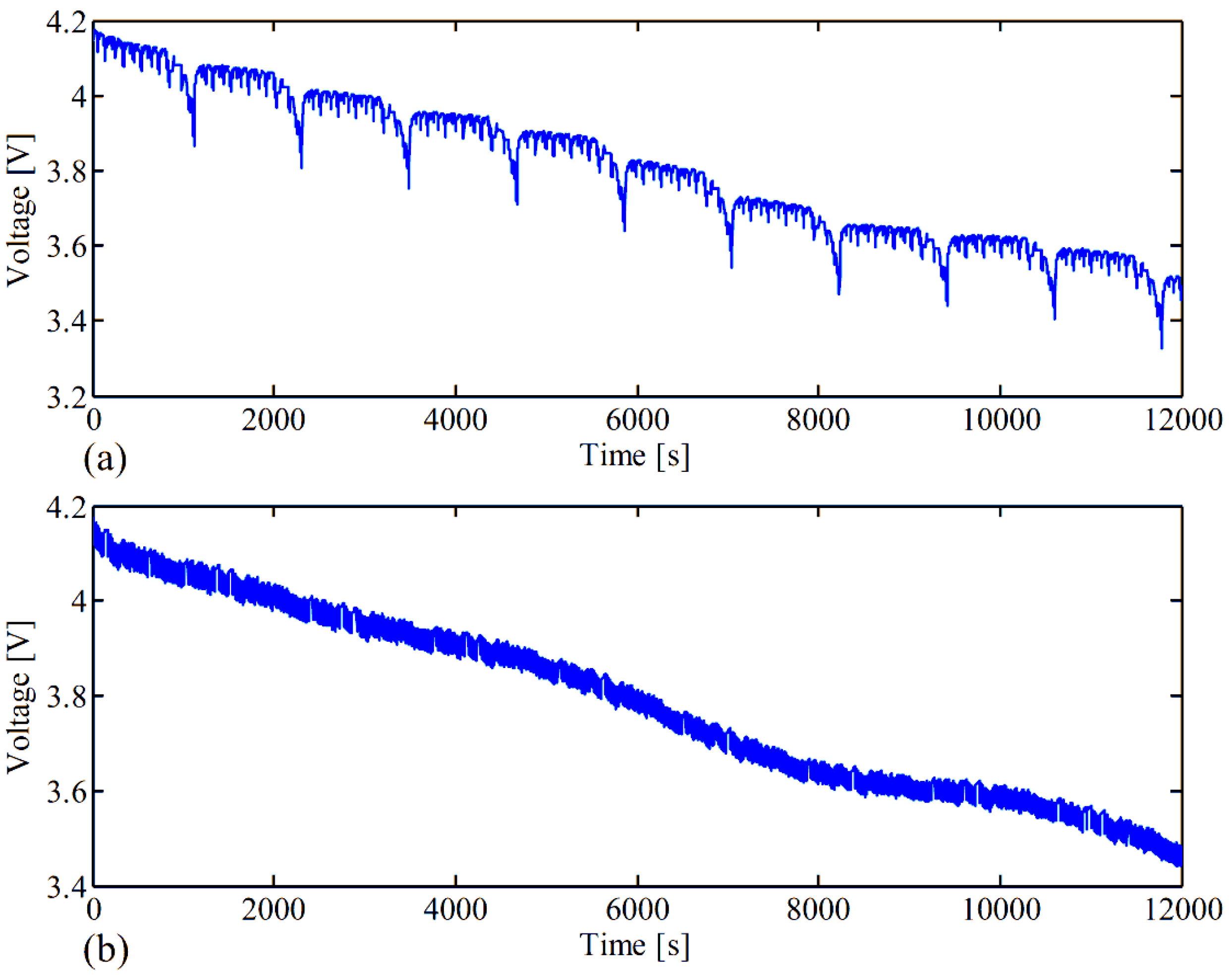
4.1. Experimental Setup

- (1)
- The battery is fully charged before it is discharged, thus, the initial SOC value can be accurately determined to be 100%;
- (2)
- A high precise current sensor is adopted to measure the battery current, so it is regarded that the measured current is accurate enough to eliminate the accumulated error.


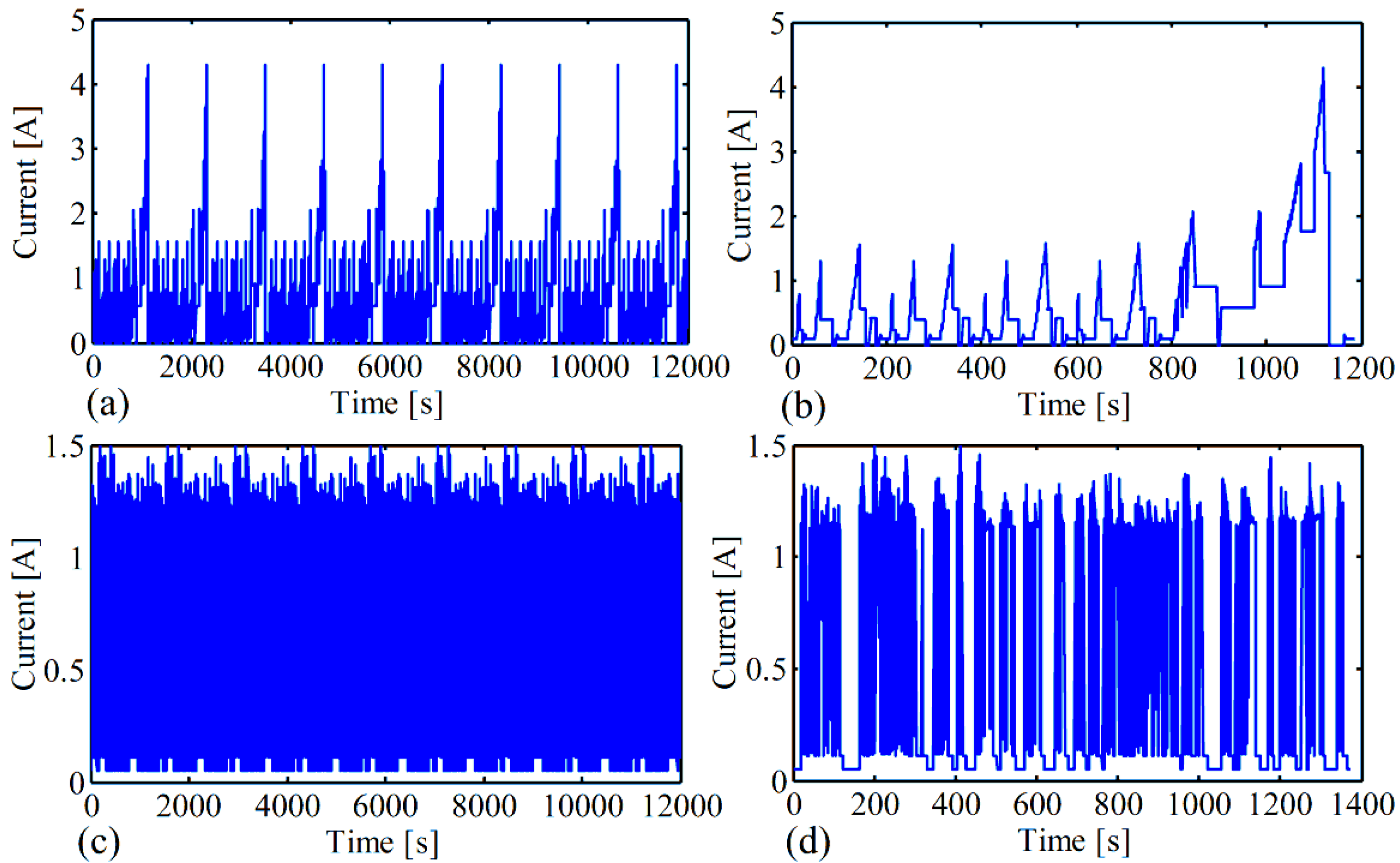
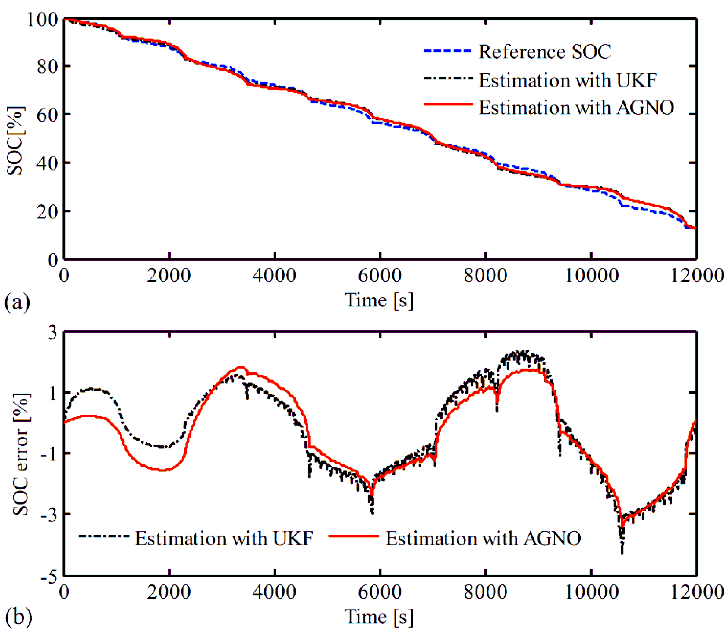
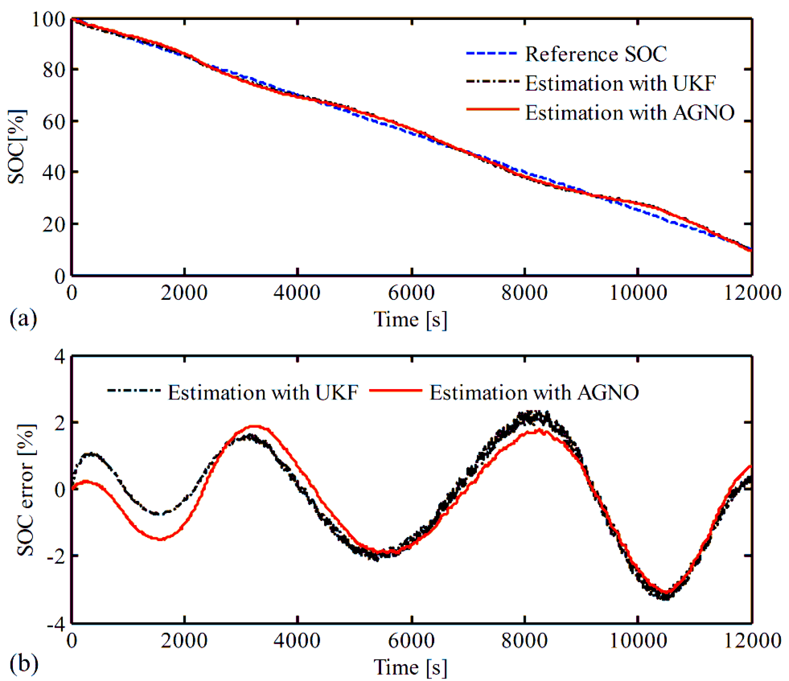
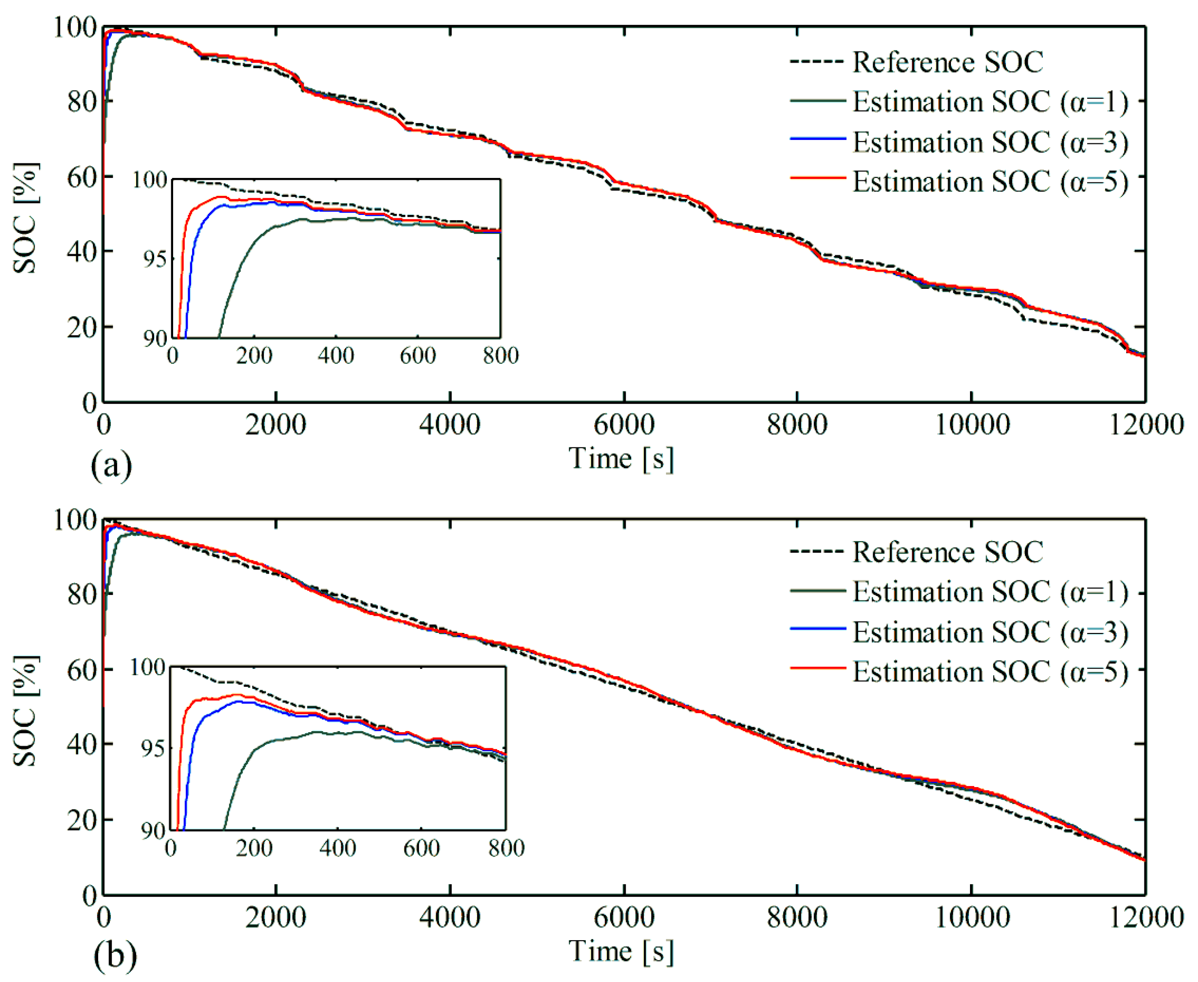
4.2. Results and Discussion


| Methods | NEDC | FUDS | ||||
|---|---|---|---|---|---|---|
| Max error | RMSE | Computation cost | Max error | RMSE | Computation cost | |
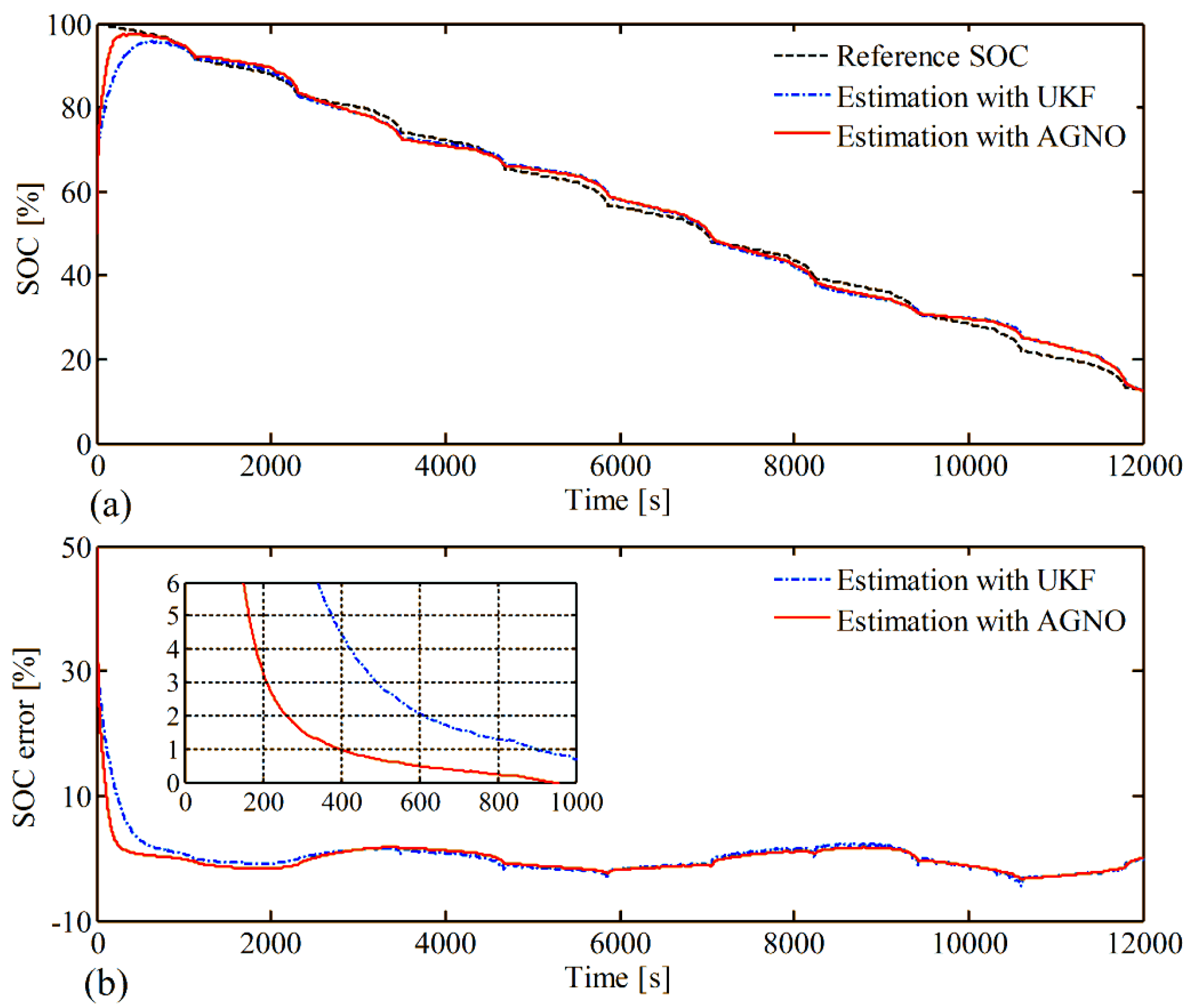
| UKF | 4.40% | 1.50% | 0.286 ms/point | 3.34% | 1.47% | 0.293 ms/point |
| AGNO | 3.41% | 1.44% | 0.057 ms/point | 3.09% | 1.42% | 0.060 ms/point |
| Initial SOC (%) | 0 | 10 | 20 | 30 | 40 | 50 | 60 | 70 | 80 | 90 | 100 |
|---|---|---|---|---|---|---|---|---|---|---|---|
| UKF | 6.10 | 5.68 | 5.23 | 4.62 | 3.93 | 3.30 | 2.77 | 2.28 | 1.82 | 1.55 | 1.50 |
| AGNO | 4.98 | 4.64 | 4.19 | 3.63 | 3.11 | 2.71 | 2.38 | 2.06 | 1.74 | 1.49 | 1.44 |
| Initial SOC (%) | 0 | 10 | 20 | 30 | 40 | 50 | 60 | 70 | 80 | 90 | 100 |
|---|---|---|---|---|---|---|---|---|---|---|---|
| UKF | 6.18 | 5.76 | 5.30 | 4.69 | 4.00 | 3.36 | 2.82 | 2.31 | 1.82 | 1.52 | 1.47 |
| AGNO | 5.00 | 4.67 | 4.22 | 3.65 | 3.13 | 2.73 | 2.39 | 2.06 | 1.73 | 1.47 | 1.42 |


| Scale factor | NEDC | FUDS | ||||
|---|---|---|---|---|---|---|
| 1 | 3 | 5 | 1 | 3 | 5 | |
| Convergence rate (s) | 165 | 50 | 27 | 176 | 52 | 28 |
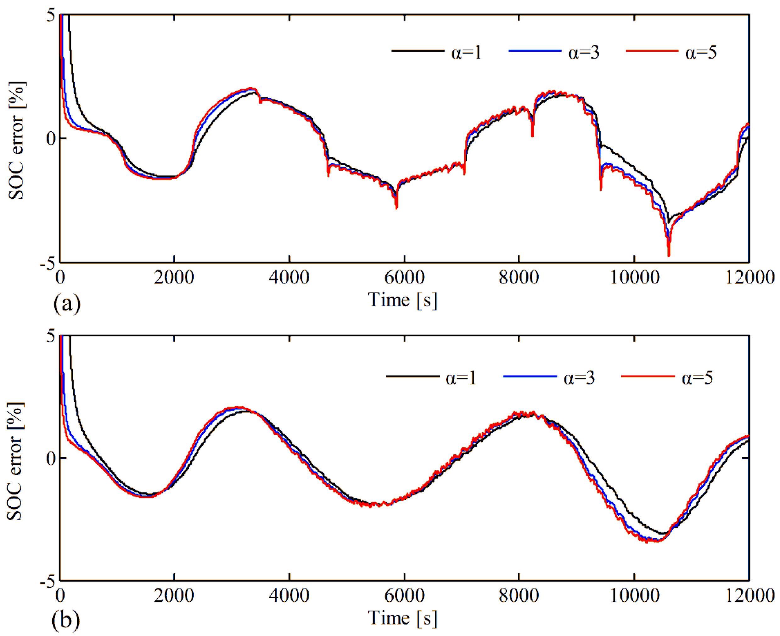
| RMSE (%) | 2.71 | 2.01 | 1.85 | 3.44 | 2.83 | 2.71 |


5. Conclusions
Acknowledgments
Author Contributions
Conflicts of Interest
References
- Lu, L.; Han, X.; Li, J.; Hua, J.; Ouyang, M. A review on the key issues for lithium-ion battery management in electric vehicles. J. Power Sources 2013, 226, 272–288. [Google Scholar] [CrossRef]
- Eddahech, A.; Briat, O.; Vinassa, J.M. Thermal characterization of a high-power lithium-ion battery: Potentiometric and calorimetric measurement of entropy changes. Energy 2013, 61, 432–439. [Google Scholar] [CrossRef]
- Koga, H.; Croguennec, L.; Ménétrier, M.; Mannessiez, P.; Weill, F.; Delmas, C. Different oxygen redox participation for bulk and surface: A possible global explanation for the cycling mechanism of Li1.20Mn0.54Co0.13Ni0.13O2. J. Power Sources 2013, 236, 250–258. [Google Scholar]
- Ng, K.S.; Moo, C.S.; Chen, Y.P.; Hsieh, Y.C. Enhanced coulomb counting method for estimation state-of-charge and state-of-health of lithium-ion batteries. Appl. Energy 2009, 86, 1506–1511. [Google Scholar]
- Shen, W.X.; Chan, C.C.; Lo, E.W.C.; Chau, K.T. A new battery available capacity indicator for electric vehicles using neural network. Energy Convers. Manag. 2002, 43, 817–826. [Google Scholar] [CrossRef]
- Li, I.H.; Wang, W.Y.; Su, S.F.; Lee, Y.S. A merged fuzzy neural network and its applications in battery state-of-charge estimation. IEEE Trans. Energy Convers. 2007, 22, 697–708. [Google Scholar] [CrossRef]
- Cheng, B.; Bai, Z.; Cao, B. State of charge estimation based on evolutionary neural network. Energy Convers. Manag. 2008, 49, 2788–2794. [Google Scholar] [CrossRef]
- Alvarez Anton, J.C.; Garcia Nieto, P.J.; Blanco Viejo, C.; Vilan Vilan, J.A. Support vector machines used to estimate the battery state of charge. IEEE Trans. Power Electron. 2013, 28, 5919–5926. [Google Scholar]
- Hansen, T.; Wang, C.J. Support vector based battery state of charge estimator. J. Power Sources 2005, 141, 351–358. [Google Scholar] [CrossRef]
- Gao, M.Y.; Liu, Y.Y.; He, Z.W. Battery State of Charge online Estimation based on Particle Filter. In Proceedings of the International Congress on Image and Signal Processing, Shanghai, Chian, 15–17 October 2011; pp. 2233–2236.
- Du, J.N.; Wang, Y.Y.; Wen, C.Y. Li-Ion Battery SOC Estimation Using Particle Filter Based on an Equivalent Circuit Model. In Proceeding of the 2013 10th IEEE International Conference on Control and Automation, Hangzhou, Zhejiang, China, 12–14 June 2013; pp. 580–585.
- He, Y.; Liu, X.T.; Zhang, C.B.; Chen, Z.H. A new model for state-of-charge (SOC) estimation for high-power Li-ion batteries. Appl. Energy 2013, 101, 808–814. [Google Scholar] [CrossRef]
- Kim, I.S. The novel state of charge estimation method for lithium battery using sliding mode observer. J. Power Sources 2006, 163, 584–590. [Google Scholar] [CrossRef]
- Zhang, F.; Liu, G.J.; Fang, L.J. A Battery State of Charge Estimation Method Using Sliding Mode Observer. In Proceedings of the World Congress on Intelligent Control and Automation, Chongqing, China, 25–27 June 2009; pp. 392–396.
- Kim, I.S. A technique for estimating the state of health of lithium batteries through a dual-sliding-mode observer. IEEE. Trans. Power Electron. 2010, 25, 1013–1022. [Google Scholar] [CrossRef]
- Chen, X.P.; Shen, W.X.; Cao, Z.W.; Kapoor, A. A novel approach for state of charge estimation based on adaptive switching gain sliding mode observer in electric vehicles. J. Power Sources 2014, 246, 667–678. [Google Scholar] [CrossRef]
- Plett, G.L. Extended Kalman filtering for battery management systems of LiPB-based HEV battery packs: Part 1. Background. J. Power Sources 2004, 134, 252–261. [Google Scholar] [CrossRef]
- Plett, G.L. Extended Kalman filtering for battery management systems of LiPB-based HEV battery packs: Part 2. Modeling and identification. J. Power Sources 2004, 134, 262–276. [Google Scholar] [CrossRef]
- Plett, G.L. Extended Kalman filtering for battery management systems of LiPB-based HEV battery packs: Part 3. State and parameter estimation. J. Power Sources 2004, 134, 277–292. [Google Scholar] [CrossRef]
- Lee, J.; Nam, O.Y.; Cho, B.H. Li-ion battery SOC estimation method based on the reduced order extended Kalman filtering. J. Power Sources 2007, 174, 9–15. [Google Scholar] [CrossRef]
- Dai, H.F.; Wei, X.Z.; Sun, Z.C.; Wang, J.Y.; Gu, W.J. Online cell SOC estimation of Li-ion battery packs using a dual time-scale Kalman filtering for EV applications. Appl. Energy 2012, 95, 227–237. [Google Scholar] [CrossRef]
- Hu, X.S.; Li, S.B.; Peng, H.; Sun, F.C. Robustness analysis of state-of-charge estimation methods for two types of Li-ion batteries. J. Power Sources 2012, 217, 209–219. [Google Scholar] [CrossRef]
- Xiong, R.; Gong, X.Z.; Mi, C.C.; Sun, F.C. A robust state-of-charge estimator for multiple types of lithium-ion batteries using adaptive extended Kalman filter. J. Power Sources 2013, 243, 805–816. [Google Scholar] [CrossRef]
- Xiong, R.; He, H.W.; Sun, F.C.; Zhao, K. Evaluation on state of charge estimation of batteries with adaptive extended Kalman filter by experiment approach. IEEE Trans. Veh. Technol. 2013, 62, 108–117. [Google Scholar] [CrossRef]
- Yuan, S.F.; Wu, H.J.; Yin, C.L. State of charge estimation using the extended Kalman filter for battery management systems based on the ARX battery model. Energies 2013, 6, 444–470. [Google Scholar] [CrossRef]
- Xiong, R.; Sun, F.C.; Gong, X.Z.; Gao, C.C. A data-driven based adaptive state of charge estimator of lithium-ion polymer battery used in electric vehicles. Appl. Energy 2014, 113, 1421–1433. [Google Scholar] [CrossRef]
- Sepasi, S.; Ghorbani, R.; Liaw, B.Y. A novel on-board state-of-charge estimation method for aged Li-ion batteries based on model adaptive extended Kalman filter. J. Power Sources 2014, 245, 337–344. [Google Scholar] [CrossRef]
- Plett, G.L. Sigma-point Kalman filtering for battery management systems of LiPB-based HEV battery packs: Part 1: Introduction and state estimation. J. Power Sources 2006, 161, 1356–1368. [Google Scholar] [CrossRef]
- Plett, G.L. Sigma-point Kalman filtering for battery management systems of LiPB-based HEV battery packs: Part 2: Simultaneous state and parameter estimation. J. Power Sources 2006, 161, 1369–1384. [Google Scholar] [CrossRef]
- Sun, F.C.; Hu, X.S.; Zou, Y.; Li, S.G. Adaptive unscented Kalman filtering for state of charge estimation of a lithium-ion battery for electric vehicles. Energy 2011, 36, 3531–3540. [Google Scholar] [CrossRef]
- Zhang, J.L.; Xia, C.Y. State-of-charge estimation of valve regulated lead acid battery based on multi-state unscented Kalman filter. Int. J. Electr. Power Energy Syst. 2011, 33, 472–476. [Google Scholar] [CrossRef]
- He, W.; Williard, N.; Chen, C.C.; Pecht, M. State of charge estimation for electric vehicle batteries using unscented Kalman filtering. Microelectron. Reliab. 2013, 53, 840–847. [Google Scholar] [CrossRef]
- Partovibakhsh, M.; Liu, G.J. An adaptive unscented Kalman filtering approach for online estimation of model parameters and state-of-charge of lithium-ion batteries for autonomous mobile robots. IEEE Trans. Control Syst. Technol. 2014, 99. [Google Scholar] [CrossRef]
- He, H.W.; Qin, H.Z.; Sun, X.K.; Shui, Y.P. Comparison study on the battery SoC estimation with EKF and UKF algorithms. Energies 2013, 6, 5088–5100. [Google Scholar] [CrossRef]
- Li, J.H.; Barillas, J.K.; Guenther, C.; Danzer, M.A. A comparative study of state of charge estimation algorithms for LiFePO4 batteries used in electric vehicles. J. Power Sources 2013, 230, 244–250. [Google Scholar] [CrossRef]
- Hu, X.S.; Li, S.B.; Peng, H. A comparative study of equivalent circuit models for Li-ion batteries. J. Power Sources 2012, 198, 359–367. [Google Scholar] [CrossRef]
- Schweighofer, B.; Raab, K.M.; Brasseur, G. Modeling of high power automotive batteries by the use of an automated test system. IEEE Trans. Instrum. Meas. 2003, 52, 1087–1091. [Google Scholar] [CrossRef]
- Hu, X.S.; Sun, F.C.; Zou, Y. Estimation of state of charge of a Lithium-ion battery pack for electric vehicles using an adaptive Luenberger observer. Energies 2010, 3, 1586–1603. [Google Scholar] [CrossRef]
- Boizot, N.; Busvelle, E.; Gauthier, J.P. An adaptive high-gain observer for nonlinear systems. Automatica 2010, 46, 1483–1488. [Google Scholar] [CrossRef]
- Xu, F.; Wang, Y.Y.; Luo, X.L. Soft sensor for inputs and parameters using nonlinear singular state observer in chemical processes. Chin. J. Chem. Eng. 2013, 21, 1038–1047. [Google Scholar] [CrossRef]
- Johansson, A.; Medvedev, A. An observer for systems with nonlinear output map. Automatica 2003, 39, 909–918. [Google Scholar] [CrossRef]
- Xing, Y.J.; He, W.; Pecht, M.; Tsui, K.L. State of charge estimation of lithium-ion batteries using the open-circuit voltage at various ambient temperatures. Appl. Energy 2014, 113, 106–115. [Google Scholar] [CrossRef]
- Xia, B.Z.; Wang, S.; Tian, Y.; Sun, W.; Xu, Z.H.; Zheng, W.W. Experimental research on the LiNixCoyMnzO2 lithium-ion battery characteristics for model modification of SOC Estimation. Inf. Technol. J. 2014, 13, 2395–2403. [Google Scholar] [CrossRef]
- Tian, Y.; Xia, B.Z.; Sun, W.; Xu, Z.H.; Zheng, W.W. A modified model based state of charge estimation of power lithium-ion batteries using unscented Kalman filter. J. Power Sources 2014, 270, 619–626. [Google Scholar] [CrossRef]
© 2014 by the authors; licensee MDPI, Basel, Switzerland. This article is an open access article distributed under the terms and conditions of the Creative Commons Attribution license (http://creativecommons.org/licenses/by/3.0/).
Share and Cite
Tian, Y.; Chen, C.; Xia, B.; Sun, W.; Xu, Z.; Zheng, W. An Adaptive Gain Nonlinear Observer for State of Charge Estimation of Lithium-Ion Batteries in Electric Vehicles. Energies 2014, 7, 5995-6012. https://doi.org/10.3390/en7095995
Tian Y, Chen C, Xia B, Sun W, Xu Z, Zheng W. An Adaptive Gain Nonlinear Observer for State of Charge Estimation of Lithium-Ion Batteries in Electric Vehicles. Energies. 2014; 7(9):5995-6012. https://doi.org/10.3390/en7095995
Chicago/Turabian StyleTian, Yong, Chaoren Chen, Bizhong Xia, Wei Sun, Zhihui Xu, and Weiwei Zheng. 2014. "An Adaptive Gain Nonlinear Observer for State of Charge Estimation of Lithium-Ion Batteries in Electric Vehicles" Energies 7, no. 9: 5995-6012. https://doi.org/10.3390/en7095995