Article

Hybrid Intelligent Control Method to Improve the Frequency Support Capability of Wind Energy Conversion Systems

Department of Energy System Engineering, Chung-Ang University, 84 Heukseok-ro, Dongjak-gu, Seoul 604-714, Korea
*
Author to whom correspondence should be addressed.
Energies 2015, 8(10), 11430-11451; https://doi.org/10.3390/en81011430
Submission received: 10 August 2015 / Revised: 21 September 2015 / Accepted: 29 September 2015 / Published: 13 October 2015
(This article belongs to the Collection Wind Turbines)

Abstract

:
This paper presents a hybrid intelligent control method that enables frequency support control for permanent magnet synchronous generators (PMSGs) wind turbines. The proposed method for a wind energy conversion system (WECS) is designed to have PMSG modeling and full-scale back-to-back insulated-gate bipolar transistor (IGBT) converters comprising the machine and grid side. The controller of the machine side converter (MSC) and the grid side converter (GSC) are designed to achieve maximum power point tracking (MPPT) based on an improved hill climb searching (IHCS) control algorithm and de-loaded (DL) operation to obtain a power margin. Along with this comprehensive control of maximum power tracking mode based on the IHCS, a method for kinetic energy (KE) discharge control of the supporting primary frequency control scheme with DL operation is developed to regulate the short-term frequency response and maintain reliable operation of the power system. The effectiveness of the hybrid intelligent control method is verified by a numerical simulation in PSCAD/EMTDC. Simulation results show that the proposed approach can improve the frequency regulation capability in the power system.

1. Introduction

Increasing concerns over the energy crisis and environmental problems have significantly promoted the development of wind energy for sustainable, efficient, and clean electric power systems all over the world [1]. In modern wind energy conversion systems (WECS), large turbines with permanent magnet synchronous generators (PMSGs) are being adopted owing to their advantages compared with other generator types, such as higher power density, efficiency, and better controllability [2,3]. However, to fully exploit the benefits of a variable speed wind turbine without a gearbox, it is important to develop advanced control methods to extract the maximum power output from wind turbines.
Previous research on this topic has focused on two control methods for extracting maximum power, namely tip speed ratio (TSR) control and power signal feedback (PSF) control [4,5]. The rotor speed of a wind turbine is changed in accordance with wind speed variations to achieve the optimal TSR value. However, the TSR control needs considerable data for the wind speed and wind turbine, which is not always available. Implementation of PSF control requires simulation of an off-line experiment on the wind turbine and is thus hampered by high practical costs. Recently, the hill climb searching (HCS) algorithm has been developed, which is attractive because of its independent power tracking characteristics as well as the simplicity of its operation system [6]. However, the traditional method of HCS may directly occur in the estimation error from a sudden change of the wind speed [7]. To solve this, the hybrid HCS method described in [8] includes optimal torque control to solve the problem of incorrect directionality under rapid wind speed changes. In [9], the authors presented a new control strategy for the induction generator in WECS using a sliding mode speed observer to estimate the rotational speed of the induction generator. However, the traditional proportional integral (PI) controller cannot ensure fast convergence to a simple linear dynamic behavior. Another approach was proposed in [10], where a modified perturbation and observation algorithm was used for the sensorless speed control loop to reduce the turbine’s mechanical stress. In this method, it is not easy to decide the appropriate step size. Too large a step size can result in more oscillation, while too small a step size reduces the convergence speed.
The increasing prevalence of large-scale WECS has also led to a discussion of frequency control research, which is necessary for a secure and reliable power system operation. The main purpose of the frequency control is to regulate the electrical supply for meeting the power demands in the standard operation of the power system, which is maintained within strict limits. In the frequency restoration process, the first few seconds after a frequency disturbance are crucial. During this period, system operators are responsible for regulating the balance between generation and demand [11]. Variable speed operation, which is controlled by the power electronic devices, enables maximum power point tracking (MPPT) control of the wind generators depending on the wind speed without any power reserves, and thus they cannot supply a certain amount of spinning reserve in response to frequency disturbances [12,13]. This control scheme also reduces the power system inertia because of the mechanical decoupling of the turbine rotating mass and the generator in the variable speed wind turbine. It can result in a significant decrease of the frequency nadir in the presence of frequency disturbances. In this respect, most variable speed wind turbines have no inherent inertial response, and consequently, negative impacts of the frequency control, such as generator tripping, are inevitable, particularly for power systems with high wind penetration [14]. Accordingly, system operators request that wind turbines provide some sort of ancillary service to enhance the frequency support capability.
Based on these facts, many papers dealing with the frequency control of wind turbines to maintain the stability and reliability of WECS have been published. One of the relevant methods of frequency control is implemented by inertial control, which is proposed to support frequency regulation by releasing energy from a rotating mass [15,16,17]. To provide the inertial response, a variable speed wind turbine has to reduce its rotor speed and thus operate at a lower performance coefficient during the frequency disturbance [15]. In [16], an additional control method is proposed that makes the “hidden inertia” available to the power system. In this way, wind turbines can emulate inertia and support the primary frequency control for some time. The authors of [17] attempted to use an inertia-contributing loop to enhance the inertia support from the wind turbine. Obviously, these controls decrease the power output necessary to recover the initial rotational speed during the system frequency regulation. In [18], the moving-average method with a K-deviation was introduced to preserve a certain amount of wind power reserve. The de-loaded (DL) control is also a key solution to extract a certain amount of power margin and kinetic energy (KE) within short duration from the connected wind turbines [19,20]. In another literature survey [21,22], the authors proposed the KE discharge control for a wind farm to actively provide a primary reserve to support a frequency disturbance based on the stored KE in a rotor. However, for a higher released amount of power margin such a KE, the rotational speed of the wind turbine will be decelerated rapidly. If the energy regain during acceleration is not controlled properly, it may cause another frequency disturbance [23]. So that it is necessary to carry out relevant research on control of both the active power and frequency regulation. In order to handle these problems, frequency control needs to be combined with the MPPT method to improve the frequency capacity compared with the conventional method. It is worth pointing out that the higher amount of available energy at times of wind speed variation may improve the efficiency of the maximum power that can be processed by the HCS. Accordingly, when there is a frequency disturbance, the frequency support capability can be improved by frequency control with HCS, leading to additional power and higher efficiency.
This paper proposes a hybrid intelligent control method that consists of an improved hill climb search (IHCS) algorithm and advanced frequency support control method for the PMSG. The IHCS algorithm enables extracting wind energy effectively even when wind conditions undergo rapid change. The algorithm is also adopted to ensure the additional power and higher efficiency in process of DL operation and KE extraction, to improve frequency support capability. The active power control attempts not only to operate the MPPT through the IHCS algorithm for various wind speeds, but also to obtain the power margin in DL control operation. After that, the frequency support control scheme based on the KE discharge control is applied to develop the frequency support capability for maintaining stability of the wind turbine system.
The remainder of the paper is organized as follows: Section 2 describes the WECS for variable speed wind turbine with PMSG. Section 3 presents the control method of WECS used to control the integrated converters and describe the DL operation Section 4 presents the proposed hybrid intelligent control method. The simulation results obtained from the proposed control method, including IHCS algorithm and frequency support control method, are presented in Section 5. Conclusions are given in Section 6.

2. Wind Energy Conversion System (WECS) Description

2.1. Variable Speed Wind Turbine Characteristics

The mechanical behavior of the wind turbine is given as follows:
J m d t = T m T e B ω m
where B is the friction coefficient of the generator, J is the moment of inertia (kg/m2), Tm is the mechanical torque, Te is the electrical torque applied to the PMSG rotor.
The mechanical rotational speed ωm of PMSG rotor is given by:
ω m = ω t G r
where ωt is the rotational speed of the wind turbine, and Gr is the gear ratio.
Among the existing wind generators, for gearless PMSG-based wind turbines, Gr = 1. The mechanical power extracted by a variable speed wind turbine Pm is expressed as:
P m = 1 2 ρ π R 2 V 3 C p ( λ , β )
where ρ is the air density (1.225 kg/m3), R is the wind turbine blade radius, V is the wind speed (m/s), β is the pitch angle, and power coefficient Cp is dependent on the TSR λ, which is defined as the ratio of the rotational speed and wind speed, expressed as [12]:
λ = ω m R V
When the pitch angle is equal to zero during MPPT operation, the power coefficient is given by:
C p ( λ,β ) = 0.23 ( 116 λ i 0.48 β 5 ) e 12.5 λ i
1 λ i = 1 λ 0.02 β 0.003 1 + β 3

2.2. Modeling of Permanent Magnet Synchronous Generator (PMSG)

The mathematical modeling of a PMSG in the d-q reference frame can be represented as follows [24]:
V d s = R s I d s L s d I d s d t + ω e L s I q s
V q s = R s I q s L s d I q s d t ω e L s I d s + ω e Ψ f
where Vds and Vqs are the stator voltages in the d and q axes, respectively, Ls and Rs represent the inductance and resistance of the PMSG winding, respectively, Ψf is the magnetic flux, Ids and Iqs are the stator currents in the d and q axes, respectively.
The electrical rotational speed ωe is represented by:
ω e = ω m p n
where pn is the number of pole pairs,
In surface-mounted PMSGs, Ids = 0, and by analyzing the behavior of the PMSG, it is obtained that the electromagnetic torque Te is determined as:
T e = 3 2 p n I q s Ψ f

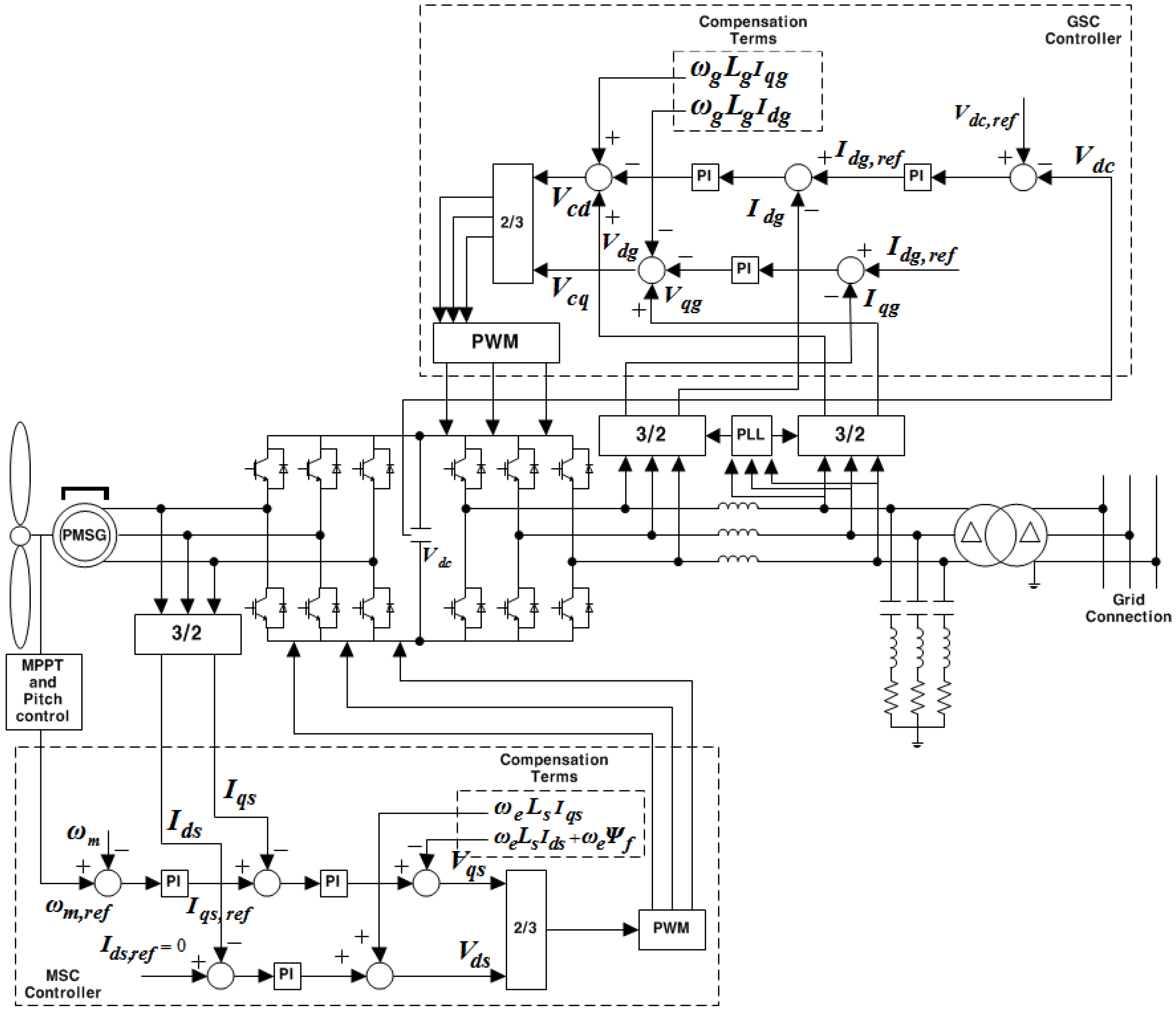
3. Control Method of Wind Energy Conversion System (WECS)

3.1. Design of the Converters Control Loop

The synchronous operation of PMSG system is typically accomplished by the machine side converter (MSC) controller, which is mainly used to regulate the wind turbine shaft speed to extract the maximum power [16]. Figure 1 shows the MSC and grid side converter (GSC) controllers with electronic regulators with two cascaded loops. In the inner loop of the MSC, the current controllers are used to regulate the d-q axes stator current to follow the reference, whereas a speed controller is used in the outer loop to regulate the wind turbine speed in such a way that it follows the reference value ωm,ref and produces the q-axis current reference Iqs,ref. The stator voltage components, Vds and Vqs, are obtained through the machine current components, Ids and Iqs, respectively, as seen in Equations (7) and (8). The stator current components cannot be controlled independently by the stator voltage components because of cross-coupling effects, which can be cancelled using feed-forward compensation. The stator voltage components are decided by PI controllers and feed-forward compensation. Additionally, the d-axis reference current Ids,ref is set to zero to minimize the current and resistive losses related to the copper losses in the stator windings. Then, a pulse width modulation (PWM) method is utilized to produce a switching signal for the MSC control.
Meanwhile, the GSC is mainly used to deliver the energy from the generator side to the power system, to regulate the DC-link voltage, and to control the reactive power with a back to back converter [25]. The inner loops of the GSC regulate the grid currents using the vector control approach, whereas the outer loops control the DC voltage and reactive power delivered to the power system. The GSC control loops in the d-q axes include a rotating reference frame and signal PI controllers. The active power reference Pref is used to maintain a constant output voltage, and Qref is determined by the power factor. Using a phase-locked loop (PLL), the three-phase current is converted into the d-q frame. The dynamic model voltage equations of the grid connection in the d-q reference frame that rotates synchronously with the grid voltage are represented as follows [3]:
V d g = V c d R g I d g L g d I d g d t + ω g L g I q g
V q g = V c q R g I q g L g d I q g d t + ω g L g I d g
where Vdg and Vqg are the grid voltages in the d and q axes, respectively, Lg and Rg are the grid inductance and resistance, respectively, ωg is the angular speed of the grid, Vcd and Vcq are the converter voltage components, Idg and Iqg are currents of the electric grid in the d and q axes, respectively.
The grid side active power Pg and reactive power Qg can be formulated in accordance with the following equations:
P g = 3 2 V d g I d g
Q g = 3 2 V d g I q g
It can be seen from Equations (18) and (19) that the active and reactive power is regulated to achieve the desired voltage by respectively adjusting the currents of the d-q axes.
Figure 1. Schematic of the control method based on permanent magnet synchronous generators (PMSG).
Energies 08 11430 g001

3.2. DC-Link Voltage Control

In order to transfer all the active power generated in the wind turbine, the DC-link voltage Vdc should be maintained at a constant value by using the current control of the d-axis [26]. Thus, the DC-link controller can be defined based on the following constraint:
C d V dc d t = P t V dc P g V dc
where C is the capacitance of the DC-link capacitor, Pt and Pg are the power of the wind turbine and grid, respectively.
If Pt and Pg are equal, there will be no change in the DC-link voltage. The measured error in the DC-link voltage is used to determine the generator power operating point via the PI controller.

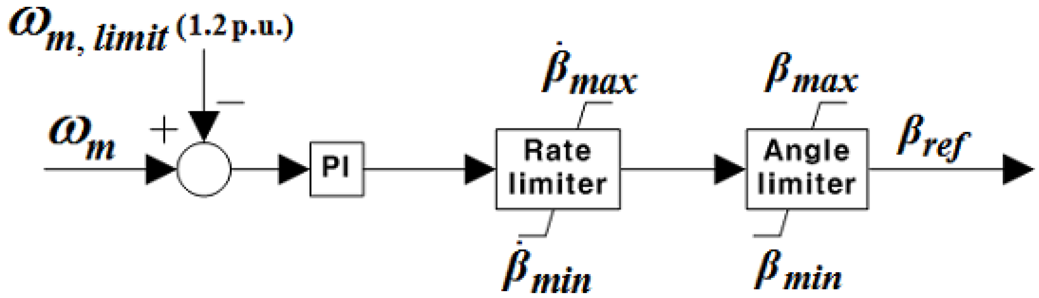
3.3. Pitch Angle Control Mode

Wind turbine systems typically operate at wind speeds ranging from 3 m/s to 25 m/s, and the rated power can be extracted at a wind speed ranging from 12 m/s to 16 m/s. Figure 2 shows the pitch angle controller used to regulate the rotational speed. When the generator power is below the rated power, or the rotational speed is below the maximum speed, the pitch angle is set to zero to obtain maximum power. The pitch angle of the wind turbine is then controlled to limit the rotational speed. If the generated power is higher than the rated value, the pitch angle is adjusted to limit the power to the maximum rated value. This study focuses on the maximum rotational speed ωm,limit of 1.2 p.u. by taking into account the reliable operation range of the PMSG, based on the current control of the MSC. The controller adjusts the pitch angle based on the comparison of ωm, and the reference pitch angle βref is defined by the PI controller.
Figure 2. Pitch angle controller.
Energies 08 11430 g002

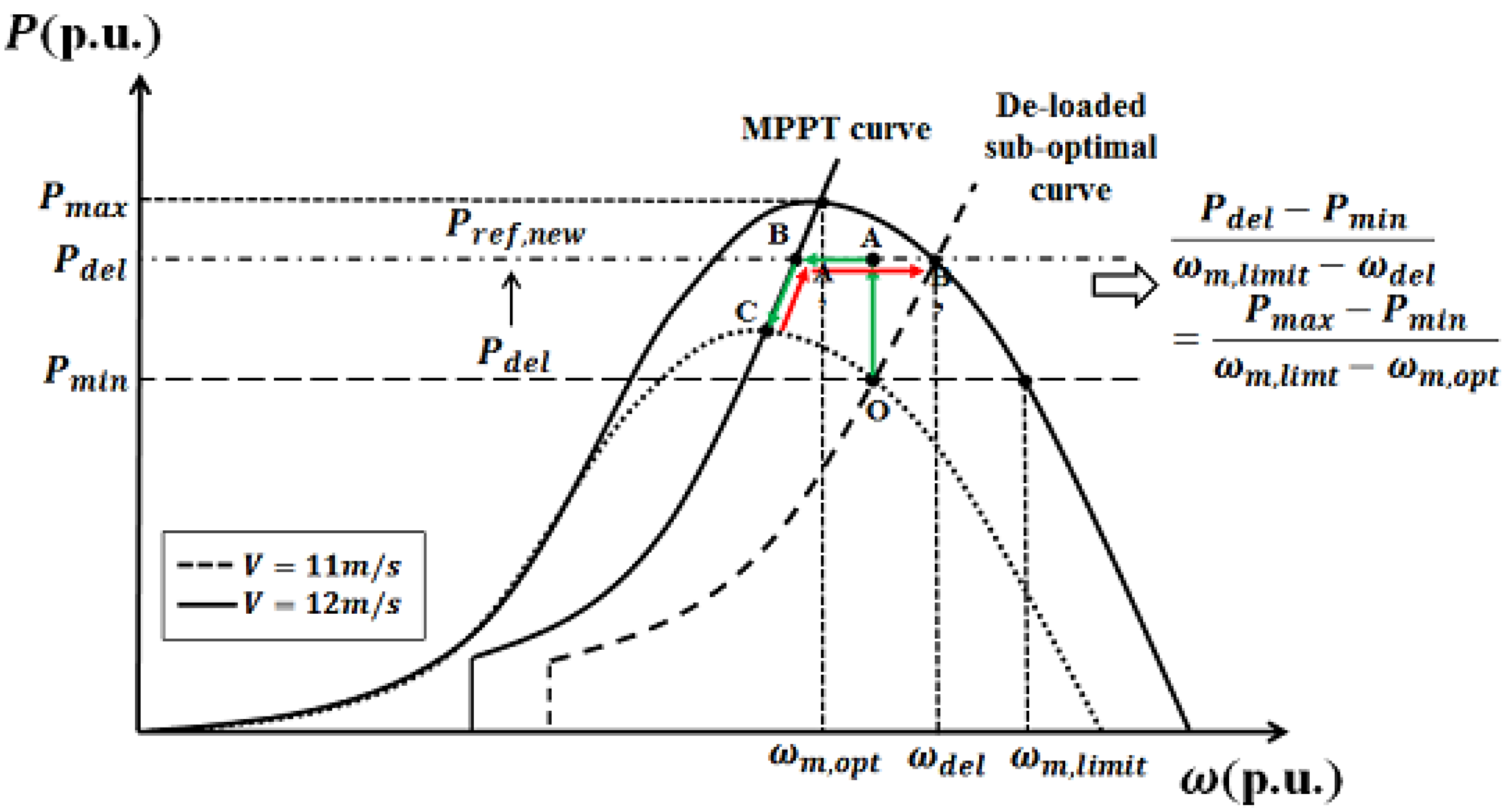
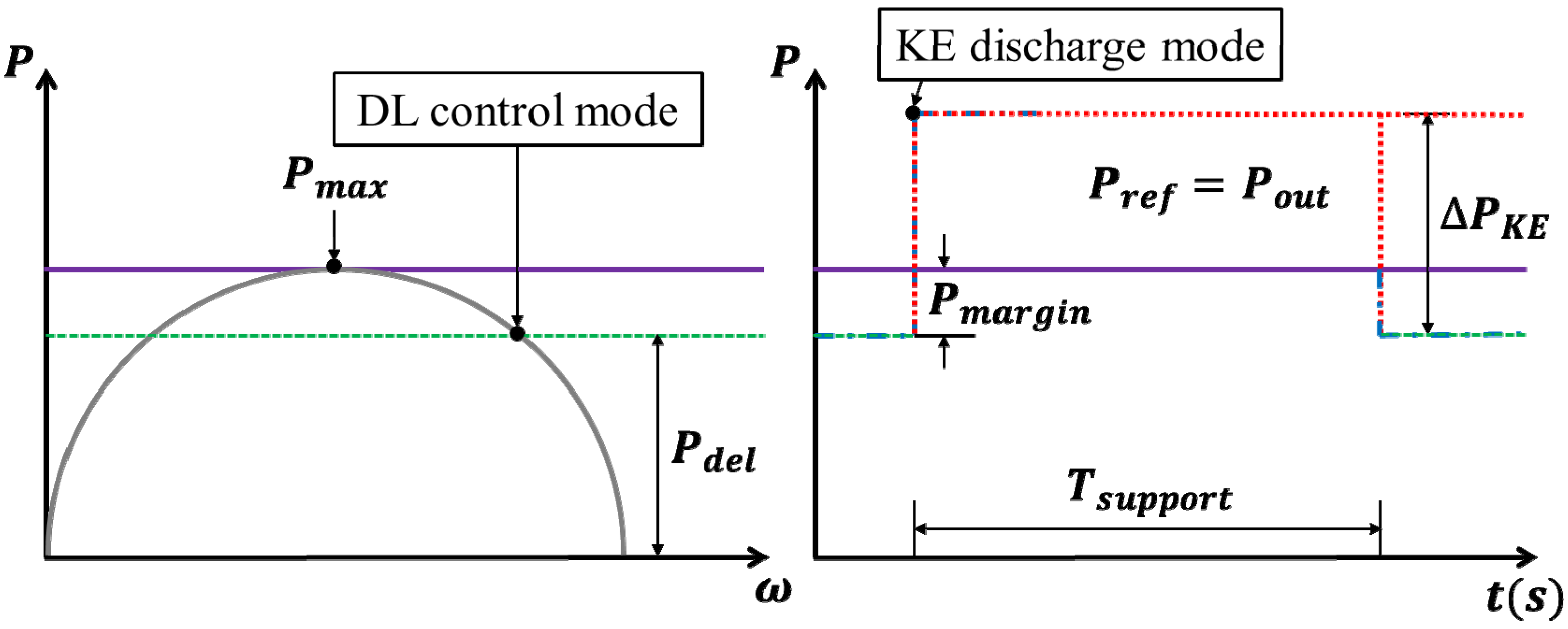
3.4. De-Loaded (DL) Operation Mode

The DL operation controls the active power output of the PMSG wind generator so as to maintain a constant output based on an MPPT curve. To participate in frequency regulation, it is necessary that the PMSGs must have a sufficient power margin available at any instant. However, this is not possible if the PMSGs are operated only under MPPT control, which aims to extract maximum energy from wind. During a sudden load increase or loss of a large generation facility, the active power reference uses the DL power tracking curve to save the available power margin for frequency regulation [20]. Thus, PMSGs need to apply DL control to ensure a sufficient power margin. The operating power reference can be calculated as:
P del = ( P max P min ) ( ω m,limit ω del ) ω m,limit ω m,opt + P min
P min = K del P max
K del = ( 1 % del 100 )
where Pdel is the DL active power reference, Pmax and Pmin are the maximum and DL active power for a given wind speed, ωm,opt is the PMSG rotational speed at Pmax, ωm,limit is the PMSG rotational speed at Pmin, Kdel is the rotational speed coefficient of DL control, and ωdel is the rotational speed reference of DL control.
For 90% DL control of a wind turbine generator, the power output Pmin = 0.90Pmax. Thus, the relationship between Pmax and Pmin is defined as:
P max = K opt ω m,opt ω m,opt 3
P min = K opt ω m,limit ω m,limit 3
where K opt ω m,opt and K opt ω m,limit are the optimal coefficients for both the rotational speed ωm,opt and ωm,limit, respectively.
From Equations (18)–(20), the rotational speed can be defined as:
ω m,limit = ω m,opt ( K del K opt ω m,opt K opt ω m,limit ) 1 3
Equation (16) can then be rewritten as:
P del = { [ ω m,opt ( K del K opt ω m,opt K opt ω m,limit ) 1 3 ω del ] + ( ω del ω m,opt ) K del [ ( K del K opt ω m,opt K opt ω m,limit ) 1 3 1 ] ω m,opt } P max
To implement the proposed DL control method, the power margin Pmargin can be calculated as:
P margin = P max P del
Figure 3 depicts the DL optimal operating power point curve for a PMSG in the high, medium, and low wind speed regions. In order to provide the power margin, the PMSG should operate along the 10% DL sub-optimal curve. For the rated wind speed V = 11 m/s, the PMSG does not operate at the maximum power point (MPP) C but at point O, so that the system can attain the 10% available power margin.
If the frequency of the power system decreases, DL active power Pdel is turned into a new output reference Pref,new. The operating point is immediately moved from point O to point A by utilizing the KE reserve of the DL control. The output is then maintained during operation. At this time, the rotational speed should be continuously decreased because of the mismatch between the wind turbine output and mechanical input. When point B is reached, the rotational speed and output are also decreased following the MPPT curve. The rotational speed is stabilized at point C (the equilibrium point), which attains an equal mechanical output and the maximum possible power for the given rotational speed. This means that the system provides the maximum possible power until the frequency of the power system is stabilized. If the maximum possible power is higher than the output reference because of the increased wind speed at 12 m/s, point C moves on to point A’ to verify the output reference, and point A’ then moves to point B’ to increase the rotational speed. The proposed DL control is used to dynamically control the q-axis current of the MSC, as shown in Figure 4.
Figure 3. Schematic diagram of the de-loaded (DL) sub-optimal operating power point curve.
Energies 08 11430 g003
Figure 4. Configuration of the DL controller.
Energies 08 11430 g004
Here, fsystem is the frequency of the power system, fnominal is the nominal frequency (60 Hz), and ωr is the speed adjustment rate. In our study, DL control mode is considered: 90% of the sub-optimal power curve.

4. Hybrid Intelligent Control Method

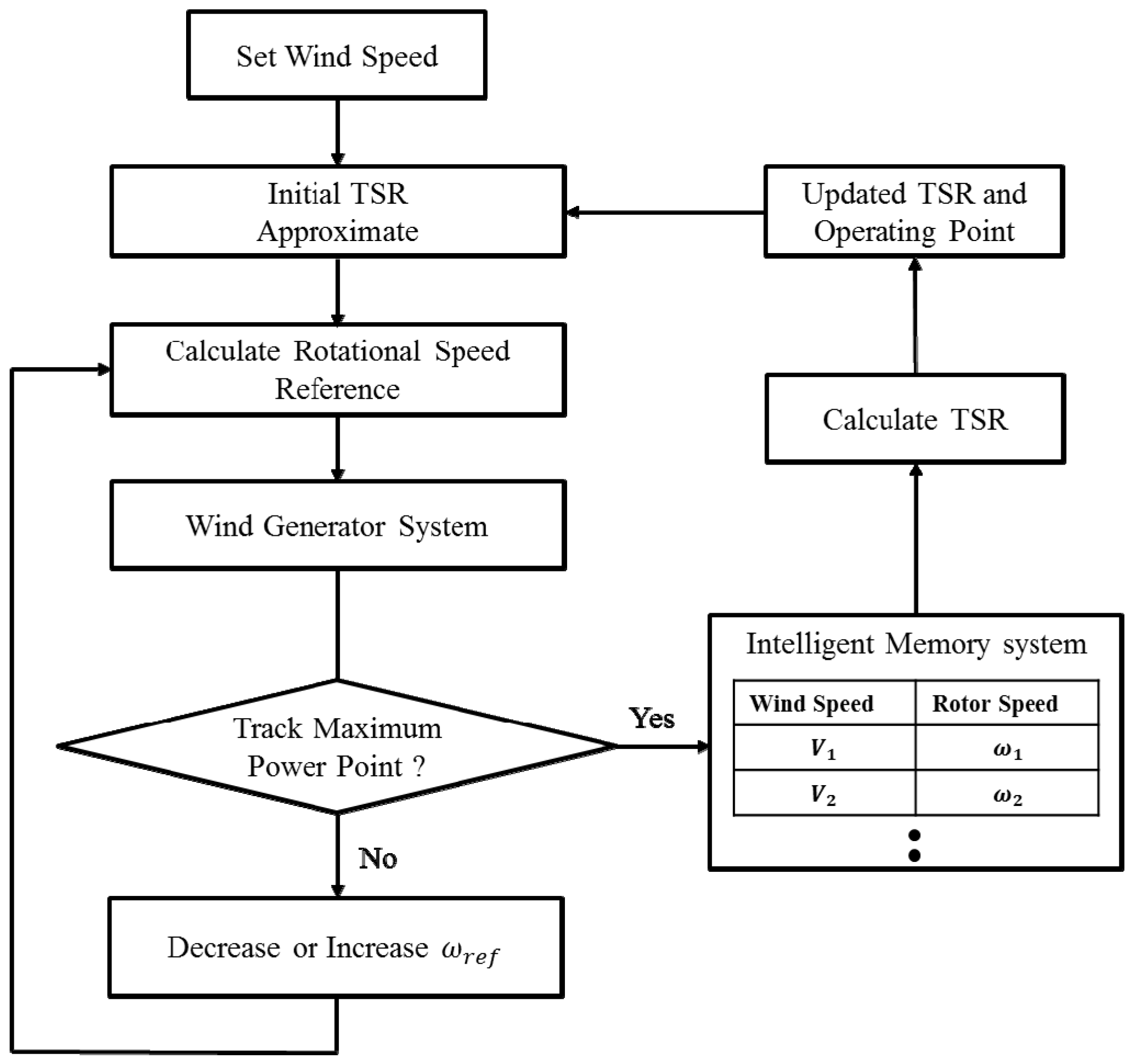
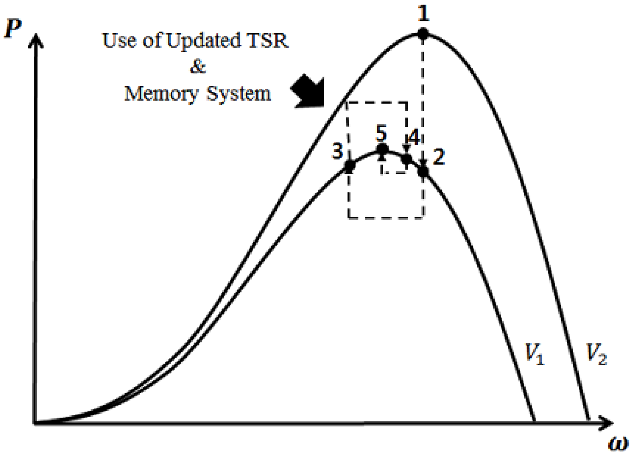
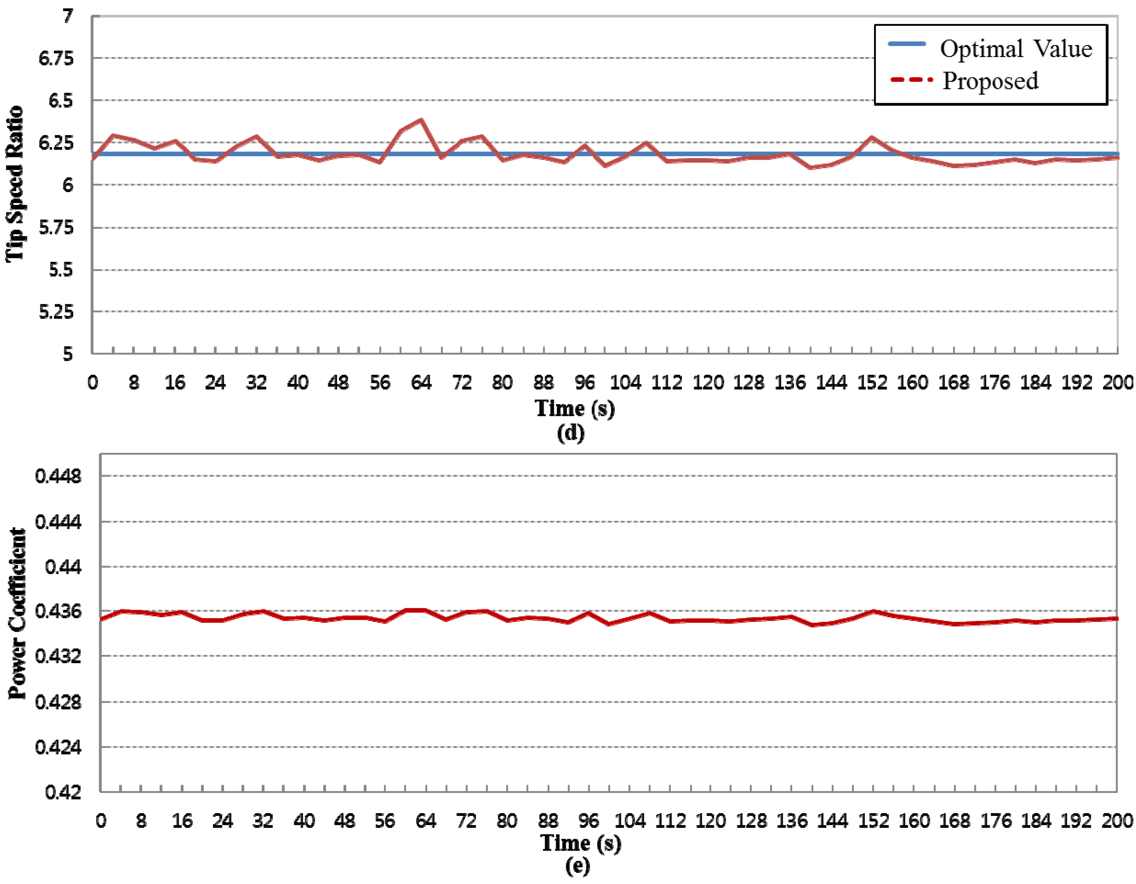
4.1. Improved Hill Climb Searching (IHCS) Algorithm

The objective of the MPPT control is to extract the maximum power from the wind speed. This is achieved with pitch angle control and current control of the q-axis. The power extracted from the wind is maximized when the rotational speed is such that the power coefficient attains its maximum value for a specific TSR. The optimal TSR λopt of the mechanical output is defined as [27]:
λ opt = ω m,opt R V
where ωm,opt is the optimal mechanical rotational speed (rad/s) for a given wind speed (m/s).
From Equations (3) and (24), the maximum power value can be obtained as a function of the shaft speed:
P max = ω m,opt 3 × K opt
K opt = 1 2 ρπ ( C p,opt λ opt 3 ) R 5
where Kopt is the coefficient of rotational speed for the maximum power through Cp,opt at the wind generator.
Due to the instantaneous variations of wind speed, the available power from wind turbine is a function of both wind speed and rotational speed. The wind speed being uncontrollable, the only way to ensure maximum energy efficiency is to control the rotational speed. The control can be achieved by such that the power coefficient attains the optimum value for a specific TSR. In this paper, a technique is proposed for the development of a maximum wind power extraction algorithm based on the variable wind speed of WECS. Among MPPT methods, the HCS method is the one that does not require any knowledge of the aerodynamics of the wind turbine. The HCS principle in WECS is to ultimately search for the MPP by perturbing the operating point and observing the corresponding change in output. However, the conventional HCS method has an important drawback, which is its inability to track the MPP when the in case of wind speed changes rapidly. To solve this, our study employs the IHCS algorithm for exactly tracking optimal power points. Figure 5 summarizes the IHCS algorithm. The algorithm can immediately search the optimal operating point, thereby reducing the searching procedure time. The intelligent memory records previously determined optimal operating points and updates the value of TSR with respect to the wind speed. In cases where the saved optimal power point may not be the ideal value, the value of calculated the TSR and the operation point are updated afterwards. Each successful determination of the MPP allows the algorithm to obtain a more accurate TSR using Equation (24). The approach is described in a sequential manner.
Figure 5. Improved hill climb searching (IHCS) algorithm.
Energies 08 11430 g005
Step 1.
Track the MPP based on the initial TSR.
Step 2.
Check the MPP. If it is satisfied, go to Step 3. Otherwise, the procedure returns to Step 1 by regulating the reference rotor speed (ωref).
Step 3.
Save the wind speed and rotor speed in the memory system.
Step 4.
Calculate the optimal TSR from the rotational speed component of the stored MPP from each wind speed in the memory system.
Step 5.
Update the TSR and operating point. Although the wind speed suddenly changes, the IHCS algorithm can trace the MPP by going through the calculation process with the initial TSR and updated TSR in the memory.
Figure 6 shows the tracking process of the IHCS algorithm. Since the algorithm is capable of detecting the change in wind speed, it immediately invokes the calculation of a near optimal operating point using the intelligent memory system when the wind speed decreases from V2 to V1. The operating point near the optimal power point can be obtained by using an anemometer and the TSR relationship. With each approximate optimum power determined using the value of TSR, the necessary rotational speed adjustments are determined so that the large change in power due to the sudden change in wind speed does not move the turbine away from its optimum point. As a result, the use of the IHCS algorithm allows the wind turbine to rapidly jump to an operating point close at the MPP. The wind turbine system can also operate at the peak of the maximum power curve for a wide range of wind speeds, and the maximum power is extracted continuously from the MPPT controller. Therefore, this method can respond not only faster but also more effectively for tracking MPP in a varying speed.
Figure 6. Tracking process of the IHCS algorithm.
Energies 08 11430 g006

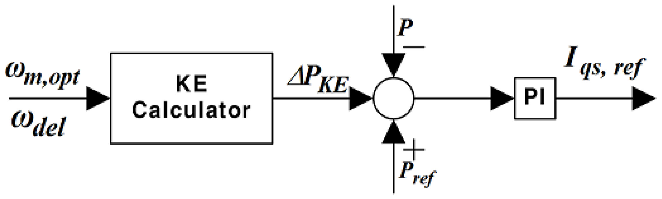
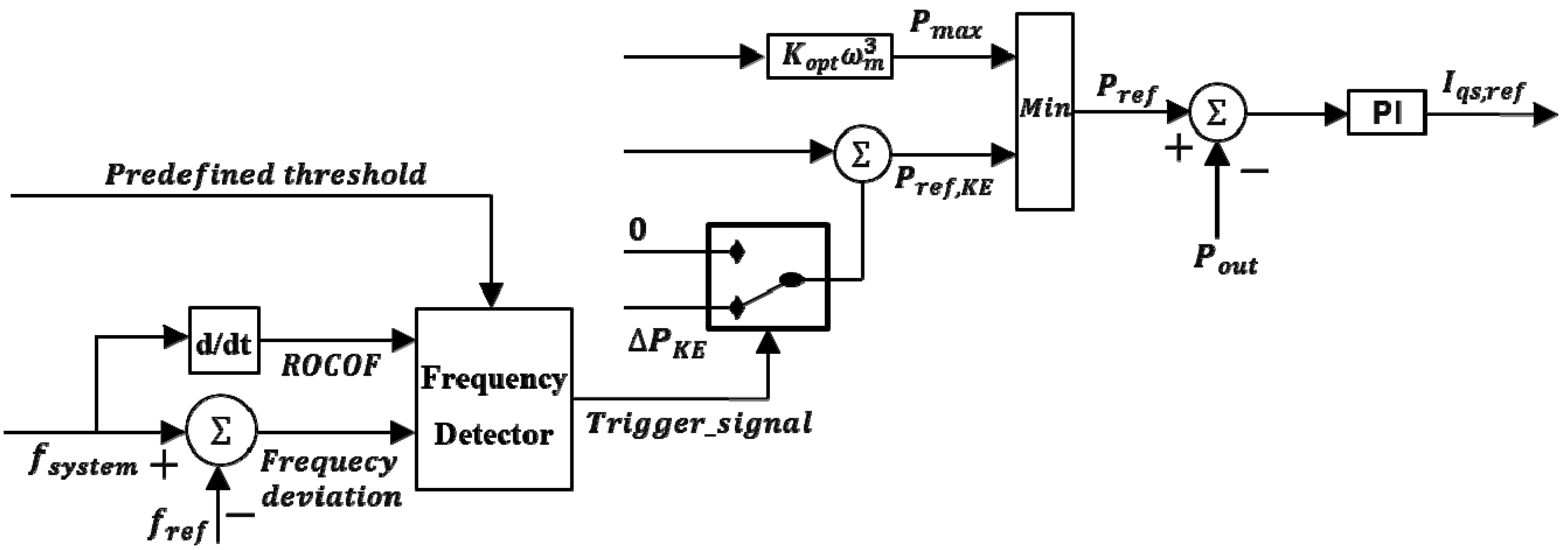
4.2. Advanced Frequency Support Control Method

The KE discharge control uses the characteristic of the full converter of the PMSG, which enables output control over a large operating range. When frequency control is required, it is also possible to receive additional power output from the KE that is stored in the wind turbine and rotor [22]. However, excessive KE discharge control may rapidly decrease the rotational speed and cause instability in the WECS. For solving this issue, an advanced frequency support control based on KE discharge control is used with active power control to maintain system stability. The proposed control attempts to provide a larger contribution to short-term frequency regulation by drawing from the KE reserve. The KE reserve can be calculated by:
K E res = J 2 ( ω del 2 ω m,opt 2 )
where J is the moment of inertia of the wind turbine.
If the KE reserve has a sufficiently large value, it can contribute to frequency control and also improve the stable frequency recovery capability of the power system. If the KE reserve from the increased rotational speed has a value large enough to provide the margin, it can contribute to the frequency control capacity of the power system, because the KE reserve can participate in the frequency control in a stable manner. Figure 7 shows the configuration of controller applying the KE discharge control.
Figure 7. Kinetic energy (KE) discharge controller.
Energies 08 11430 g007
Figure 8 shows a diagram of the proposed frequency support control. Under the normal operating conditions, the PMSG attempts to control the active power output for ensuring the existence of a power margin through the DL control mode. If the frequency decreases because of disturbances in the power system, the DL control mode switches to the KE discharge mode. The change immediately increases the output Pdel of the PMSG in accordance with the power increment ∆PKE. During the support time Tsupport, its output is maintained to allow its engagement in frequency control. In other words, Pout is increased by ∆PKE, which is stored in the rotor, and the rotational speed decreases because of the KE discharge.
Figure 8. Schematic diagram of frequency support control.
Energies 08 11430 g008
The relationship between the mechanical output Pm, and the rotational speed ωm of the KE discharge control is defined as:
J ω m m d t = P m ( P ref + Δ P K E )
When the output of the PMSG is equal to the maximum possible power for a given wind speed, the KE discharge mode operation is stopped, and the output of PMSG is then maintained until the support time Tsupport. After the PMSG has returned to the normal operating conditions, the output can be recovered via the DL control mode. As shown Figure 9, the event detector measures the power system frequency and the rate of frequency change to execute the proposed frequency support control by a modified rotor current control of the q-axis. The trigger signal for changing to the KE discharge mode is determined based on the deviation of the frequency in the power system. Thus, it generates a trigger signal by a continuous comparison of the predefined threshold value with the measured system frequency value. The PMSG system operates in the KE discharge mode as prompted by the trigger signal only when the critical frequency nadir is identified by the trigger module.
Figure 9. Modified frequency detection and trigger signal scheme.
Energies 08 11430 g009
The rate of change of frequency (ROCOF) of the power system at the initial frequency event is determined by the following equation:
d f sys d t = 2 H sys Δ P loss f nominal
where ∆Ploss is the active power shortage under the grid fault, Hsys is the equivalent inertia of the entire power system.
Equation (29) indicates that the amount of active power shortage can be calculated by the ROCOF of the power system, and it represents the security index of the grid fault. In this study, the proposed frequency control is combined with the proposed HCS to achieve a higher frequency capacity than in conventional methods. It is worth pointing out that the available energy during times of wind speed variation can improve the efficiency of maximum power using the IHCS algorithm. When a frequency disturbance occurs, the frequency support control must provide additional power, which is possible to ensure by the IHCS algorithm.

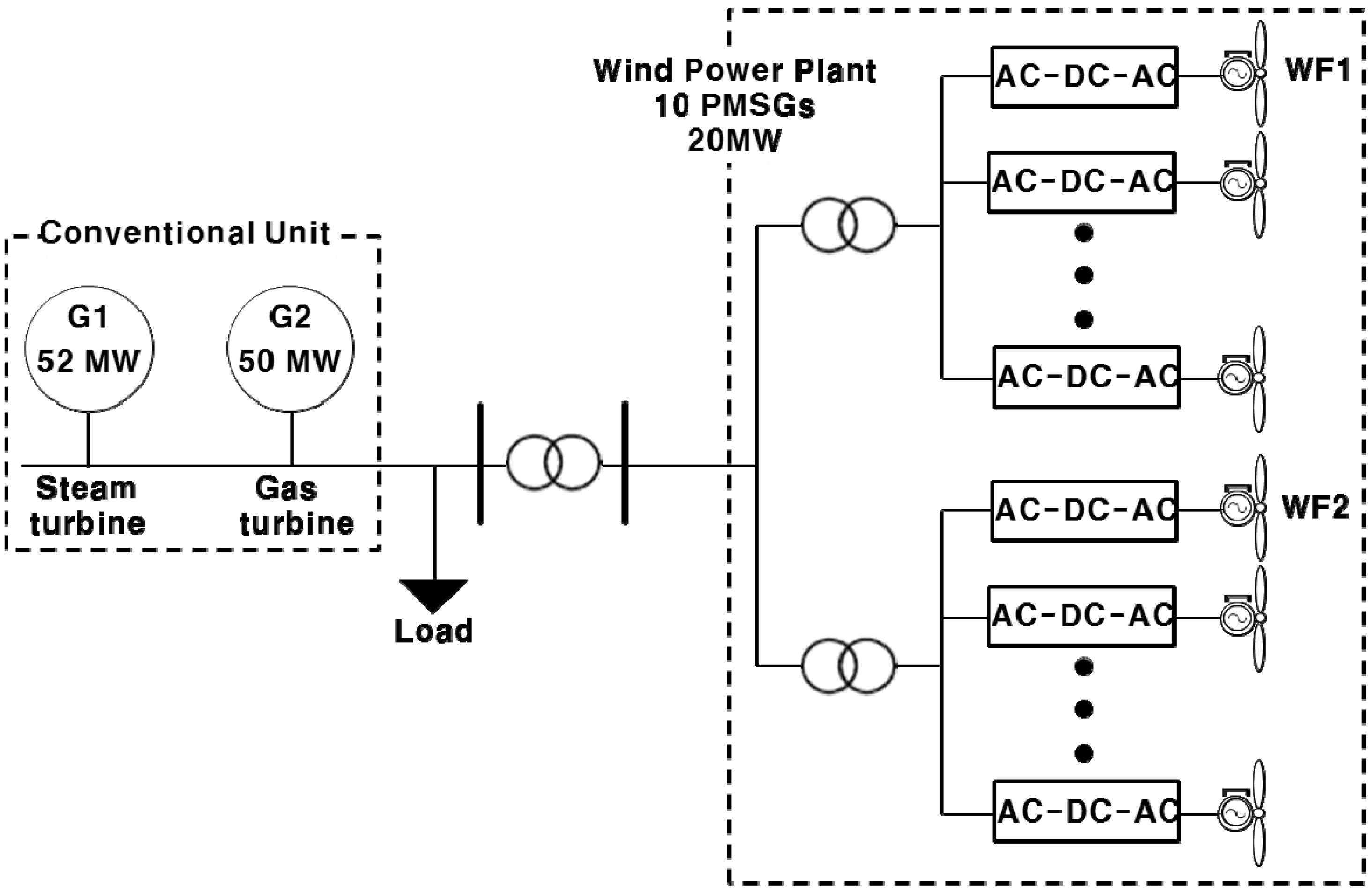
5. Case Study and Results

To validate the effectiveness of the proposed control method, a small power system was considered, as shown in Figure 10. The system consists of wind farms and a conventional power generation unit, which includes synchronous generators. The conventional unit combines a 52 MW G1 steam turbine and a 50 MW G2 gas turbine. The wind farms WF1–WF2, which are based on PMSG wind turbines, have an installed capacity of 10 MW each, and are connected to the small power system via a transformer and transmission cable. The individual wind farms are composed of five PMSG wind turbines rated at 2 MW each. The load was also modeled to have a linear frequency dependency on active power characteristics. The rated frequency of the system was set to be 60 Hz. The simulation results were analyzed by the PSCAD/EMTDC software using the parameters listed in Table 1 and Table 2.
Figure 10. Configuration of the small power system.
Energies 08 11430 g010
Table 1. PMSG wind turbine generator parameters.
ParametersNotationValue
Blade radiusR38 m
Air densityρ1.205 kg/m2
Maximum power coefficientCp,max0.4412
Rated wind speedVw,rated12 m/s
Rated generator powerPm,rated2 MW
Rated RMS line-to-line voltageVm,rated0.69 kV
Rated machine speedωm,rated376.99 rad/s
Pole pairsP11
Gen.+Turbine inertia const.H5.7267 s
PM fluxΨf136 Wb
Stator d-axis inductanceLmd0.334 H
Stator q-axis inductanceLmq0.217 H
Stator leakage inductanceLsi0.0334 H
Stator resistanceRs0.08 Ω
Table 2. Steam and gas turbine synchronous machine model parameters.
ParametersValue
Steam TurbineGas Turbine
H5.4 s1.86 s
Xd1.456 p.u. 1.94 p.u.
X d ˙ 0.206 p.u. 0.2259 p.u.
X d ¨ 0.147 p.u. 0.1723 p.u.
X d 0 ˙ 3.735 s10.4 s
X d 0 ¨ 0.032 s0.03 s
Xl0.161 p.u. 0.15 p.u.
Xq1.405 p.u. 1.92 p.u.
X q ˙ 0.500 p.u. 0.402 p.u.
X q ¨ 0.147 p.u. 0.1723 p.u.
X q 0 ˙ 0.305 s0.83 s
X q 0 ¨ 0.080 s0.055 s
Rated RMS L-N voltage7.976 kV7.976 kV
Rated RMS line current0.2008 kA0.2008 kA

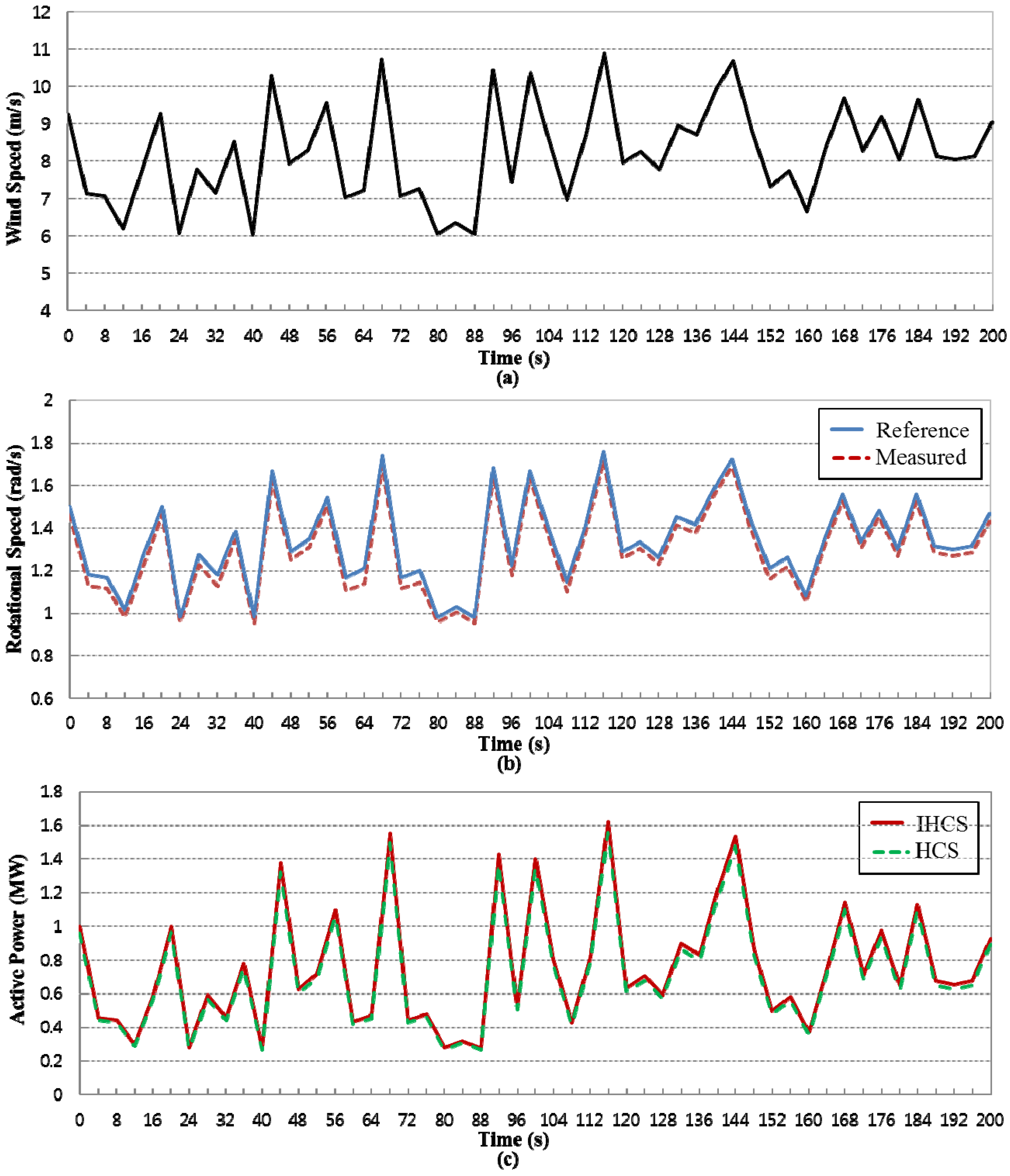
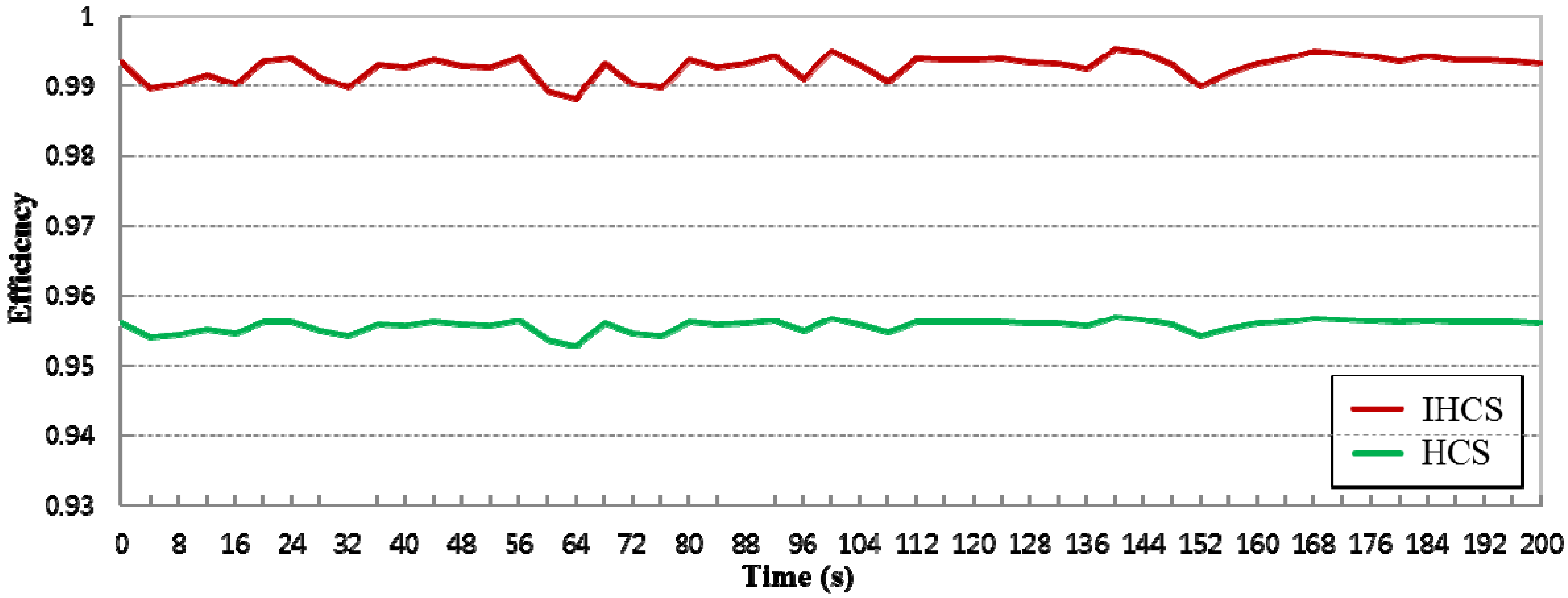
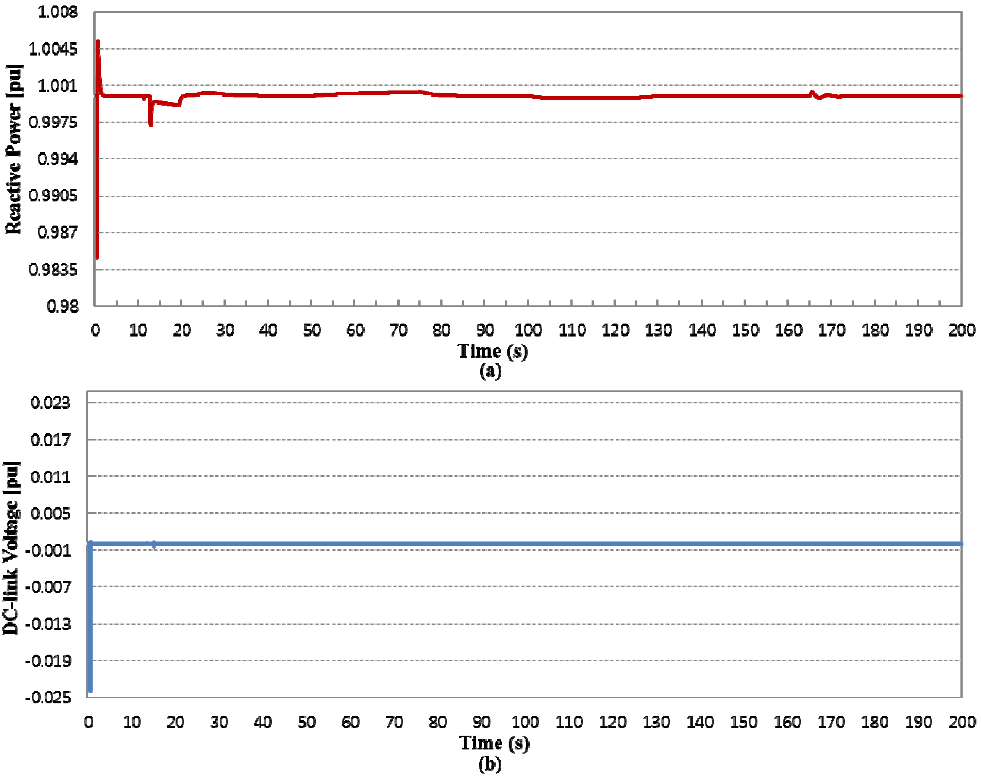
5.1. Dynamic Performance Test of an Individual Permanent Magnet Synchronous Generator (PMSG)

In this study, the proposed control method was implemented to examine the performance of the wind turbine characteristic with the IHCS algorithm. The IHCS has been compared with the conventional HCS method operating under the same wind speed profile. The experiment shown in Figure 11a was conducted by applying a series of ascending and descending slopes for the wind speed, under which the overall performance of the proposed method was evaluated. The wind speed loop responded to all wind speed values based on the appropriate monitoring of the reference speed set both for the upward and downward slopes. Figure 11b shows that the rotational speed varies rapidly with the ramp rate at a fast changing wind speed profile compared with the conventional HCS method. During the descending wind speed, the IHCS algorithm exhibited slowdown resulting in a decrease the rotational speed as compared with the HCS method. On the other hand, during an increase in rotational speed, the IHCS algorithm exhibited a very steep slope compared with the previous method. The rotational speed loop also followed the optimum speed with a limitation, which was achieved by activating the pitch controller. Figure 11c shows that the proposed IHCS algorithm extracted the maximum power from the PMSG wind turbine more precisely and at a faster rate compared with the conventional HCS method. When the wind speed increased, the active power increased proportionally, and thus active power almost coincided with the variation of the wind speed to approach the value of the added available power. In addition, the wind turbine operated with the maximum power coefficient, and the pitch angle was kept at the optimal value around. Hence, the control scheme of the MSC gives appropriate performance and it appears feasible to use the IHCS algorithm for PMSG-based wind turbine. Figure 11d,e show the variation of TSR and power coefficient. It was clearly observed that the TSR and power coefficient were always around the optimal value. The TSR value is always around 6.18 and the power coefficient is 0.435, which shows good performance of the controller with the IHCS method.
From the simulation results above comparing the performance of MPPT methods, we can see that MPPT is important for both high and low wind speeds. Figure 12 shows the efficiency of the maximum power extraction. Compared with the conventional HCS method, the efficiency value was higher even after a change in wind speed, by an average amount of 3.73. Table 3 shows the average power, increasing power percentage, and efficiency from each MPPT method. It should also be noted that, during such rapid wind speed changes, the conventional HCS method requires too much time to reach its optimum operation point and hence becomes very inefficient.
Figure 11. (a) Wind speed profile for PMSG wind turbine; (b) variation of rotational speed; (c) variation of active power; (d) variation of tip speed ratio (TSR); (e) variation of power coefficient.
Energies 08 11430 g011aEnergies 08 11430 g011b
Figure 12. Variation of efficiency.
Energies 08 11430 g012
Table 3. Comparison with conventional HCS and IHCS.
MethodControl Characteristic
Average Power (MW)Increasing Power PercentageEfficiency
Conventional HCS0.721955-95.59
IHCS0.7501123.754%99.32
Figure 13 shows the DC-link voltage and reactive power for the generator to realize the feasibility of the GSC. It can be seen that the DC-link controller provides a good agreement between the actual and reference values of the DC-link. Consequently, the actual DC-link voltage had an almost constant value of 1 p.u. over the whole period, except for the jump start at 0 s, as shown in Figure 13a. The reactive power fed to the grid was approximately zero, as shown in Figure 13b, because the GSC controller performed to keep the required constant value of 0 Mvar, i.e., unit power factor. The simulation results show good dynamic performance, enabling the desired operation of the PMSG wind turbine.
Figure 13. (a) Variation of reactive power; (b) variation of DC-link voltage.
Energies 08 11430 g013

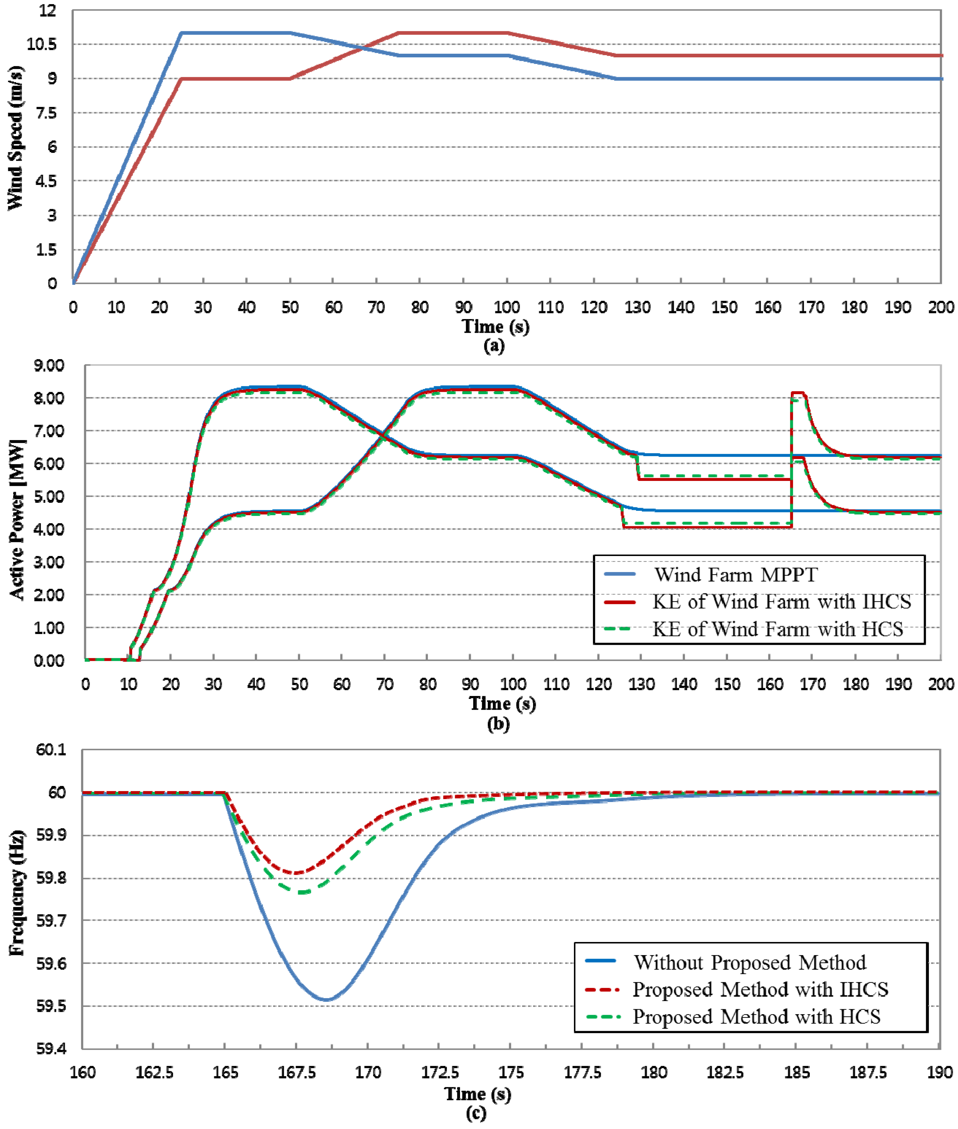
5.2. Simulation Result of the Proposed Hybrid Intelligent Control Method

Finally, the proposed control method was compared with that of advanced frequency support control with conventional HCS and no frequency control when a frequency disturbance occurs. Figure 14a shows the variable wind speed in each of the wind farms, which was applied to observe their control capabilities under stable operation. Figure 14b shows the variation of active power of the wind farms when using the proposed control method. The wind turbine operated on the MPPT condition with the IHCS algorithm to track the MPP by continuously changing the maximizing variable and observing the power captured. At 125 to 165 s, the wind turbine was operated at 10% initial DL operation mode. The reduction of active power was achieved using the available over-speeding in the PMSG. The rotational speed increased rapidly, while the active power decreased during the DL operation period. The KE reserve can be obtained from the rotating mass in DL operation of a PMSG wind turbine. This indicates that compared to the conventional methods, the IHCS can rapidly detect any wind speed conditions during the operation of WECS. Thus, when the wind turbine is operated at 10% initial DL operation mode, the proposed IHCS algorithm can provide remarkably more available active power than the conventional methods. This is because the IHCS is quite fast in reaching the optimal value, whereas the previous method gets confused during the wind change. When the system exhibited a sudden drop caused by an additional 20 MW load at 160 s, the KE discharge control mode was performed, thus releasing additional KE. The KE reserve from the rotor mass of the PMSG wind turbine was obviously larger than the normal maximum possible power during a constant period. It can also be concluded that a larger KE reserve is possible using the IHCS algorithm, compared with the power tracked by the conventional methods.
Figure 14. (a) Wind speed profile for WF1 and WF2; (b) variation of active power for WF1 and WF2; (c) frequency deviation.
Energies 08 11430 g014
As shown in Figure 14c, the frequency recovery of the proposed control method was much faster than that of other methods, and hence, in the overall wind farm the obtained larger DL power with the IHCS algorithm was realized with a greater power margin as compared with the other methods. The minimum frequency responses of the proposed strategy for the 10% DL operation modes were 59.81 Hz. These results showed that the proposed control method had greater efficiency, a better transient response and more stability that the base case by utilizing both the IHCS algorithm and the frequency support control method. The IHCS algorithm was an important factor for the effectiveness and feasibility of the proposed strategy. Consequently, the proposed method can not only supply more power to slightly improve the system frequency response, but also further develop the frequency support capability of WECS.

6. Conclusions

This paper presented a hybrid intelligent control method that combines active power control and an advanced frequency support control method based on the PMSG for application under varying wind speed conditions. The WECS was designed to encompass PMSG modeling and control of the MSC and GSC. The MSC control focused on achieving MPPT based on the IHCS algorithm for tracking the MPP and using DL operation to obtain a power margin, while the GSC control was used to keep the DC-link voltage at a set value for minimizing energy losses. The IHCS algorithm overcomes the difficulties of conventional HCS methods caused by sudden changes in the wind speed condition. A frequency support control based on the KE discharge control was provided to enhance the frequency support capability. A simulation was conducted to demonstrate the dynamic performance of the WECS control method with the IHCS algorithm for an individual PMSG and the effectiveness of the proposed control method for an entire wind farm under conditions of frequency disturbance. The IHCS algorithm extracted maximum power at a faster rate than the conventional HCS method while requiring no knowledge of the system parameters. It always operated the system toward MPP despite the wind speed variations, and improved the efficiency of MPPT to a maximum by perturbing the operating point and observing the corresponding change in output. To contribute to the frequency regulation, the DL operation provided not only a power margin reserve by de loading the sup-optimal extraction curve, but also a KE reserve based on the rotational speed, using the IHCS algorithm. The frequency support control can significantly improve the initial and low frequency issues compared with conventional methods. Consequently, the proposed hybrid intelligent control method provides a valuable contribution to the short-term frequency regulation.

Acknowledgments

This research was supported by the Chung-Ang University Research Scholarship Grants in 2014. This research was also supported by Korea Electric Power Corporation through Korea Electrical Engineering & Science Research Institute.

Author Contributions

Shin Young Heo carried out the main body of research, Mun Kyeom Kim reviewed the work continuously and Jin Woo Choi provided essential information. All authors read and approved the manuscript.

Conflicts of Interest

The authors declare no conflict of interest.

References

  1. Heier, S. Wind Energy Power Plants. In Grid Integration of Wind Energy, 2nd ed.; John Wiley & Sons: London, UK, 2006. [Google Scholar]
  2. Ruuskanen, V.; Immonen, P.; Nerg, J.; Pyrhonen, J. Determining electrical efficiency of permanent magnet synchronous machines with different control method. Electr. Eng. 2012, 94, 97–106. [Google Scholar]
  3. Chinchilia, M.; Arnaltes, S.; Burgos, J.C. Control of permanent-magnet generator applied to variable-speed wind-energy systems connected to the grid. IEEE Trans. Energy Convers. 2006, 21, 130–135. [Google Scholar] [CrossRef]
  4. Datta, R.; Ranganathan, V.T. A method of tracking the peak power points for a variable speed wind energy conversion system. IEEE Trans. Energy Convers. 2003, 18, 163–168. [Google Scholar] [CrossRef]
  5. Barakati, S.M.; Kazerani, M.; Aplevich, J.D. Maximum power tracking control for a wind turbine system including a matrix converter. IEEE Trans. Energy Convers. 2009, 24, 705–713. [Google Scholar] [CrossRef]
  6. Jadhav, H.T.; Roy, R. A comprehensive review on the grid integration of doubly fed induction generator. Int. J. Electron. Power Energy Syst. 2013, 49, 8–18. [Google Scholar] [CrossRef]
  7. Dalala, Z.M.; Zahid, Z.U.; Yu, W.; Cho, Y.; Lai, J.S. Design and Analysis of an MPPT Technique for Small-Scale Wind Energy Conversion Systems. IEEE Trans. Energy Convers. 2013, 28, 756–767. [Google Scholar] [CrossRef]
  8. Gonzalez, L.G.; Figueres, E.; Carranza, O. Maximum-power-point tracking with reduced mechanical stress applied to wind-energy-conversion-systems. Appl. Energy 2010, 87, 2304–2312. [Google Scholar] [CrossRef]
  9. Lalouni, S.; Rekioua, D.; Idjdarene, K.; Tounzi, A. Maximum Power Point Tracking Based Hybrid Hill-climb Search Method Applied to Wind Energy Conversion System. Electric. Power Compon. Syst. 2015, 43, 1028–1038. [Google Scholar] [CrossRef]
  10. Lin, W.M.; Hong, C.M.; Cheng, F.S. Fuzzy neural network output maximization control for sensorless wind energy conversion system. Energy 2015, 35, 592–601. [Google Scholar] [CrossRef]
  11. Hafiz, F.; Abdennour, A. Optimal use of kinetic energy for the inertial support from variable speed wind turbines. Renew. Energy 2015, 80, 629–643. [Google Scholar] [CrossRef]
  12. Alaboudy, A.H.K.; Daoud, A.A.; Desouky, S.S.; Salem, A.A. Converter controls and flicker study of PMSG-based grid connected wind turbines. Ain Shams Eng. J. 2013, 4, 75–91. [Google Scholar] [CrossRef]
  13. Morimoto, S.; Nakayama, H.; Sanada, M.; Takeda, Y. Sensorless output maximization control for variable-speed wind generation system using IPMSG. IEEE Trans. Ind. Appl. 2005, 41, 60–67. [Google Scholar] [CrossRef]
  14. Mullance, A.; O’Malley, M. The inertial response of induction-machine-based wind turbines. IEEE Trans. Power Syst. 2005, 20, 1496–1503. [Google Scholar] [CrossRef]
  15. Morren, J.; de Haan, S.W.H.; Kling, W.L.; Ferreira, J.A. Wind turbines emulating inertia and supporting primary frequency control. IEEE Trans. Power Syst. 2006, 21, 433–434. [Google Scholar] [CrossRef]
  16. Ramtharan, G.; Ekanayake, J.B.; Jenkins, N. Frequency support from doubly fed induction generator wind turbines. Renew. Power Gener. IET 2007, 1, 3–9. [Google Scholar] [CrossRef]
  17. Conroy, J.F.; Watson, R. Frequency response capability of full converter wind turbine generators in comparison to conventional generation. IEEE Trans. Power Syst. 2008, 23, 649–656. [Google Scholar] [CrossRef]
  18. Chien, L.R.C.; Lin, W.T.; Yin, Y.C. Enhancing frequency response control by DFIGs in the high wind penetrated power systems. IEEE Trans. Power Syst. 2011, 26, 710–718. [Google Scholar] [CrossRef]
  19. Almeida, R.G.; Lopes, J.A.P. Participation of doubly fed induction wind generators in system frequency regulation. IEEE Trans. Power Syst. 2007, 22, 944–950. [Google Scholar] [CrossRef]
  20. Almeida, R.G.; Castronuovo, E.D.; Pecas, J.A. Optimum generation control in wind parks when carrying out system operator requests. IEEE Trans. Power Syst. 2006, 21, 718–725. [Google Scholar] [CrossRef]
  21. Kayikci, M.; Milanovic, J.V. Dynamic contribution of DFIG-based wind plants to system frequency disturbances. IEEE Trans. Power Syst. 2009, 24, 859–867. [Google Scholar] [CrossRef]
  22. Keung, P.K.; Li, P.; Banakar, H.; Ooi, B.T. Kinetic energy of wind-turbine generators for system frequency support. IEEE Trans. Power Syst. 2009, 24, 279–287. [Google Scholar] [CrossRef]
  23. Ganjefar, S.; Ghasemi, A.A. A novel-strategy controller design for maximum power extraction in standalone windmill systems. Energy 2014, 76, 326–335. [Google Scholar] [CrossRef]
  24. Zhang, S.; Tseng, K.J.; Vilathgamuwa, D.M.; Nguyen, T.D.; Wang, X.Y. Design of a robust grid interface system for PMSG-based wind turbine generators. IEEE Trans. Ind. Electron. 2011, 58, 316–328. [Google Scholar] [CrossRef]
  25. Fernandez, L.M.; Garcia, C.A.; Jurado, F. Operating capability as a PQ/PV node of a direct-drive wind turbine based on a permanent magnet synchronous generator. Renew. Energy 2010, 35, 1308–1318. [Google Scholar] [CrossRef]
  26. Muyeen, S.M.; Takahashi, R.; Murata, T.; Tamura, J. A variable speed wind turbine control strategy to meet wind farm grid code requirements. IEEE Trans. Power Syst. 2010, 25, 331–340. [Google Scholar] [CrossRef]
  27. Li, S.; Haskew, T.A.; Xu, L. Conventional and novel control designs for direct driven PMSG wind turbines. Electr. Power Syst. Res. 2010, 80, 328–338. [Google Scholar] [CrossRef]

