Article

Impact of the Converter Control Strategies on the Drive Train of Wind Turbine during Voltage Dips

National Active Distribution Network Technology Research Center, School of Electrical Engineering, Beijing Jiaotong University, Beijing 100044, China
*
Author to whom correspondence should be addressed.
Energies 2015, 8(10), 11452-11469; https://doi.org/10.3390/en81011452
Submission received: 5 August 2015 / Revised: 18 September 2015 / Accepted: 18 September 2015 / Published: 13 October 2015
(This article belongs to the Special Issue Wind Turbine 2015)

Abstract

:
The impact of converter control strategies on the drive train of wind turbines during voltage dips is investigated in this paper using a full electromechanical model. Aerodynamics and tower vibration are taken into consideration by means of a simulation program, named FAST. Detailed gearbox and electrical subsystems are represented in MATLAB. The dynamic response of electromagnetic torque and its impact on the mechanical variables are the concern in this paper and the response of electrical variables is less discussed. From the mechanical aspects, the effect of rising power recovery speed and unsymmetrical voltage dips are analyzed on the basis of the dynamic response of the high-speed shaft (HSS). A comparison of the impact on the drive train is made for two converter control strategies during small voltage dips. Through the analysis of torque, speed and tower vibration, the results indicate that both power recovery speed and the sudden torque sag have a significant impact on drive trains, and the effects depend on the different control strategies. Moreover, resonance might be excited on the drive train by an unbalanced voltage.

Graphical Abstract

1. Introduction

In recent years, wind turbine generation systems have experienced a significant increase of penetration in electrical grids around the world. There has been a similar growth in the structural size and power output of single wind turbines. Correspondingly, much attention has been paid to the service life and reliability of their mechanisms because of the high production and maintenance costs. Wind turbines should have the ability to operate in low voltage ride-through (LVRT) conditions and with other disturbances. However, the impact on drive train due to these electrical disturbances is not negligible and threatens the safe operation of mechanical parts.
Considerable studies have been performed on the dynamic response and behavior analysis of doubly fed induction generators (DFIGs) under grid fault conditions [1,2,3,4,5]. The transients of current and voltage lead to large generator torque oscillations. Some strategies were proposed to mitigate the unwanted torque oscillation for unbalance voltage conditions [4,5]. Some efforts were focused on the impact on mechanical parts. Papathanassiou and Papadopoulos [6] highlighted the effect of torque transients and their propagation in the drive train for fixed speed wind turbines. Symmetrical and unsymmetrical faults, reclosing operations, phase interruptions and system voltage unbalance were examined. An approach to develop a simplified mechanical model applicable to commercial wind turbine validation was proposed in [7]. A comparison on the response of mechanical parts under single-phase and a three-phase voltage dip conditions was studied. In [8], the dynamic response of transmitted torque onto the gears in each stage due to the small voltage dip (90%) was analyzed and a detailed gearbox was built in Simscape [9]. Moreover, the transmitted loads through the high-speed shaft (HSS) with different stiffness to the gearbox were evaluated. The results in [10] showed that lateral tower vibration will be severer when a wind turbine is working at higher speed and connected to a weaker power system. Under grid fault conditions, the control effect of converters is always evaluated from the electric aspect. In fact, the impact on the drive train will be quite different due to the different control strategies implemented in the converter. This aspect has been less studied in previous works.
In this paper, the rising speed effect of power recovery, the reference value effect of electromagnetic torque during a small voltage dip and the torque response under unbalance voltage conditions are investigated based on the mechanical variables, such as HSS torque, generator speed and tower vibration. The DFIG 1.5-MW wind turbine model used in this paper considers the interaction among the aerodynamic, mechanical and electrical subsystems through co-simulation of the software package FAST (Fatigue, Aerodynamics, Structures and Turbulence) [11] and Matlab/Simulink. The aerodynamics of the turbine rotor, the dynamics of the low-speed shaft (LSS) and tower are achieved using FAST. However, mechanical dynamics is paid great attention rather than the electrical variables. The rest of the paper is organized as follows: Section 2 describes the modeling method of full electromechanical model and the converter control strategies are introduced in Section 3. Comparisons of the simulation results are shown and analyzed in Section 4. Finally, Section 5 concludes with the main results.

2. Modeling of Drive Train and Electrical Subsystems

The drive train in a DFIG wind turbine generally consists of LSS, gearbox, HSS, generator and coupling. Gearbox, as the weakest component, should receive the greatest focus. Electrical disturbances are likely to exert a detrimental effect on the gearbox. This effect is mainly expressed in the torsional vibration system which can be built based on the mathematical expressions and implemented in Matlab/Simulink. The main parameters of a DFIG wind turbine are listed in Table 1 and others are listed in the Appendix (Table A1).
Table 1. Main parameters of the wind turbine. HSS: high-speed shaft.
ParametersValueParametersValue
Rated wind speed11 m/sRated power1.5 MW
Rated rotor speed1.82 rad/sRated voltage (line to line)690 V
Gearbox ratio103.6Frequency50 Hz
Rotor diameter70 mGenerator inertia about HSS90 kg·m2
Tower height82.38 mHub inertia about rotor axis34.6 × 103 kg·m2

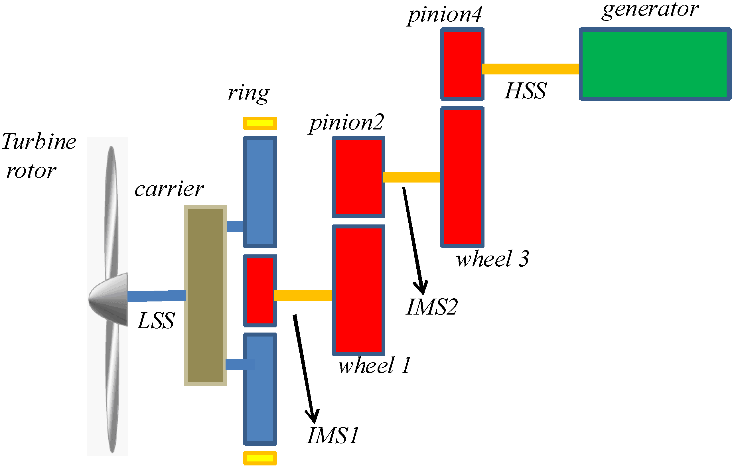
2.1. Drive Train Model

HSS is very sensitive to disturbances from the generator. The loads with higher frequencies can be filtered when transmitted from HSS to LSS [6,8,12]. A purely torsional drive train with nine degrees of freedom (DOFs) is essential for investigation of the dynamic response. In this work, it consists of one planetary stage and two parallel stages, and the computer-aided engineering (CAE) model is shown in Figure 1. It is assumed that three planets share the same loads at any time. Then the three can be equalized to one planet meshing with a ring and sun gear. The meshing force in the transversal plane and reaction torque on the gear can be expressed as follows:
{ F mesh = K m ( r 1 θ 1 r 2 θ 2 ) + D m ( r 1 θ 1 r 2 θ 2 ) T 1 = F mesh r 1 T 2 = T 1 = F mesh r 2
where Fmesh is the meshing force, Km is the mean value of meshing stiffness, Dm is the meshing damping, r1 and θ1 are the base circle radius and rotation angle of driven gear, r2 and θ2 are the base circle radius and rotation angle of the driving gear, T1 and T2 are the reaction torque on driven and driving gear, respectively. Torsional vibration on the shafts can be expressed as:
Δ T = K Δ θ + D Δ θ
where K is the torsional stiffness, D is the torsional damping and ∆θ is the angular displacement difference.
Figure 1. Gearbox in three dimensions.
Energies 08 11452 g001
A schematic of the drive train is shown in Figure 2, considering the coupling on the generator side as a part of HSS in the model. Damping has a negligible effect on the mode frequencies and system stability. Therefore, a linear time invariant mathematical model can be expressed as Equation (3):
J θ + K θ = T
Figure 2. Schematic of the drive train. LSS: low-speed shaft; IMS1: intermediate shaft between stage 1 and stage 2; IMS2: intermediate shaft between stage 2 and stage 3.
Energies 08 11452 g002
The components in the above matrixes are described by Equation (4), and the stiffness matrix is shown in Equation (5):
{ J = d i a g [ J rot , J cp , J p , J s , J 1 , J 2 , J 3 , J 4 , J gen ] J cp = J c + 3 m p r bc 2 / cos 2 α θ = [ θ rot , θ cp , θ p , θ s , θ 1 , θ 2 , θ 3 , θ 4 , θ gen ] T T = [ T aero , 0 ,   0 ,   0 ,   0 ,   0 ,   0 ,   0 , T e ] T
K = [ K LSS K LSS 0 0 0 0 0 0 0 K LSS 3 r bc ( K pr r r + K ps r s ) + K LSS 3 r bc ( K ps r p K pr r p ) 3 r bc K ps r s 0 0 0 0 0 0 3 r bp ( K ps r s K pr r r ) 3 ( K pr + K ps ) r p 2 3 r bp K ps r s 0 0 0 0 0 0 3 K ps r s 2 3 r s K ps r p K IMS1 + 3 K ps r s 2 K IMS1 0 0 0 0 0 0 0 K IMS1 K IMS1 + K 1 r 1 2 K 1 r 1 r 2 0 0 0 0 0 0 0   K 1 r 1 r 2 K IMS2 + K 1 r 2 2 K IMS2 0 0 0 0 0 0 0 K IMS2 K IMS2 + K 2 r 3 2 r 3 r 4 K 2 0 0 0 0 0 0 0 r 3 r 4 K 2 K HSS + K 2 r 4 2 K HSS 0 0 0 0 0 0 0 K HSS K HSS ]
where JX is the inertia of drive train components, X ∈ {turbine rotor (rot), carrier and the planet gears (cp), carrier only (c), sun gear (s), planet (p), generator (gen), parallel gear components (1,2,3,4)}; θX is the angular displacement of drive train components; rX is the basic circle radius of gears, and rr is basic circle radius of ring gear, rbc is the effective radius of carrier; KY is the torsional stiffness of shafts, Y ∈ {LSS, HSS, intermediate shaft between stage 1 and stage 2 (IMS1), intermediate shaft between stage 2 and stage 3 (IMS2)}; Ki is the meshing stiffness of gear pair, i ∈ {planet and ring (pr), planet and sun (ps), gear pair in stage 2 in Equation (1), gear pair in stage 3 in Equation (2)}; Taero is the aerodynamic torque and Te is the electromagnetic torque; mp is the mass of planet and α is pressure angle of planet gears.
Inertia and mass values are from the CAE model while the stiffness and damping values are estimated according to an experimental method [13,14]. Eigenfrequencies can be derived by K and J. As shown in Table 2, the mode at 0 Hz corresponds to the kinematic rotation of the system.
Table 2. Eigenfrequencies of the drive train.
ModeFrequency (Hz)ModeFrequency (Hz)
106950
22.672523.3
317583370
432896782.3
5920--

2.2. Electrical Model

In order to accelerate the simulation speed, the grid is modeled as a voltage source. The transformer that connects the wind turbine to the grid is not taken into account, and the grid voltage dip is simplified to the dip at DFIG terminals. The unbalance voltage dips are idealized to single-phase and two-phase voltage dips with other phases at the rated value.

2.2.1. Generator

DFIG expressions are represented in abc frame for grid fault analysis and written as [15]:
{ u s = R s i s + j ω s φ s + s d t u r = R r i r + j ( ω s ω r ) φ r + r d t φ s = L s i s L m i r φ r = L r i r L m i s
where u is the voltage, R is the resistance, i is the current, ωs is the synchronous electric speed, φ is the flux linkage, Lm is the mutual inductance between stator and rotor windings. The subscript s and r denote the stator and rotor quantities. Electromagnetic torque is represented as:
T e = n p L m [( i sA i ra + i sB i rb + i sC i rc )sin θ r + ( i sA i rb + i sB i rc + i sC i ra )sin( θ r + 2 π / 3 ) + ( i sA i rc + i sB i ra + i sC i rb )sin( θ r 2 π / 3 )]
where np is the number of pole pairs, θr is the electrical angle. The subscript sA, sB, sC denote the three phase of stator and ra, rb, rc denote the three phase of rotor.

2.2.2. Converter

The IGBT back-to-back converter is modeled as two controlled voltage sources without any disturbance from the switching noise. A rotor side converter (RSC) is used to provide decoupled control of the active and reactive power while the grid side converter (GSC) is mainly used to ensure a constant voltage of DC-link [16]. In this paper, RSC is highlighted for controlling the electromagnetic torque while the reactive power control is not taken into account.
Stator-flux orientation is used for the RSC control in which the stator flux is collinear with the d-axis. The expressions of the electromagnetic torque can be found in [15], and stator reactive power is set to zero. The rotor current reference value in d-q frame can be resolved:
{ i rd = φ s L m i rq = 2 3 L s L m φ s T ecmd
where Tecmd is the reference signal of electromagnetic torque from wind turbine controller.
Resolving Equation (6), splitting the rotor voltage in d-q components and taking stator flux transients into account gives:
{ u rd = R r i rd + δ L r d i rd d t ω slip δ L r i rq + E rd u rq = R r i rq + δ L r d i rq d t + ω slip δ L r i rd + ω slip φ s L m L s + E rq
where:
ω slip = ω s ω r δ = 1 L m 2 L s L r
Erd, Erq are the counter electromotive force due to the stator flux transients and described as:
{ E rd = L m L s ( u sd R s i sd ) E rq = L m L s ( u sq R s i sq ω s φ s )
In normal operation, the diagram of RSC control is depicted in Figure 3, where the decoupling of d-q control-loops is achieved by adding the feed-forward compensation after the (proportional-integral) PI controller. Rotor voltage in abc frame is obtained from RSC and used for electromagnetic torque calculation by Equations (6) and (7). Vdc is the voltage of DC-link and used for the modulation of voltage. The rated value of Vdc is 1100 V.
Figure 3. Decoupled control block diagrams of the rotor side converter (RSC). DFIG: doubly fed induction generators.
Energies 08 11452 g003

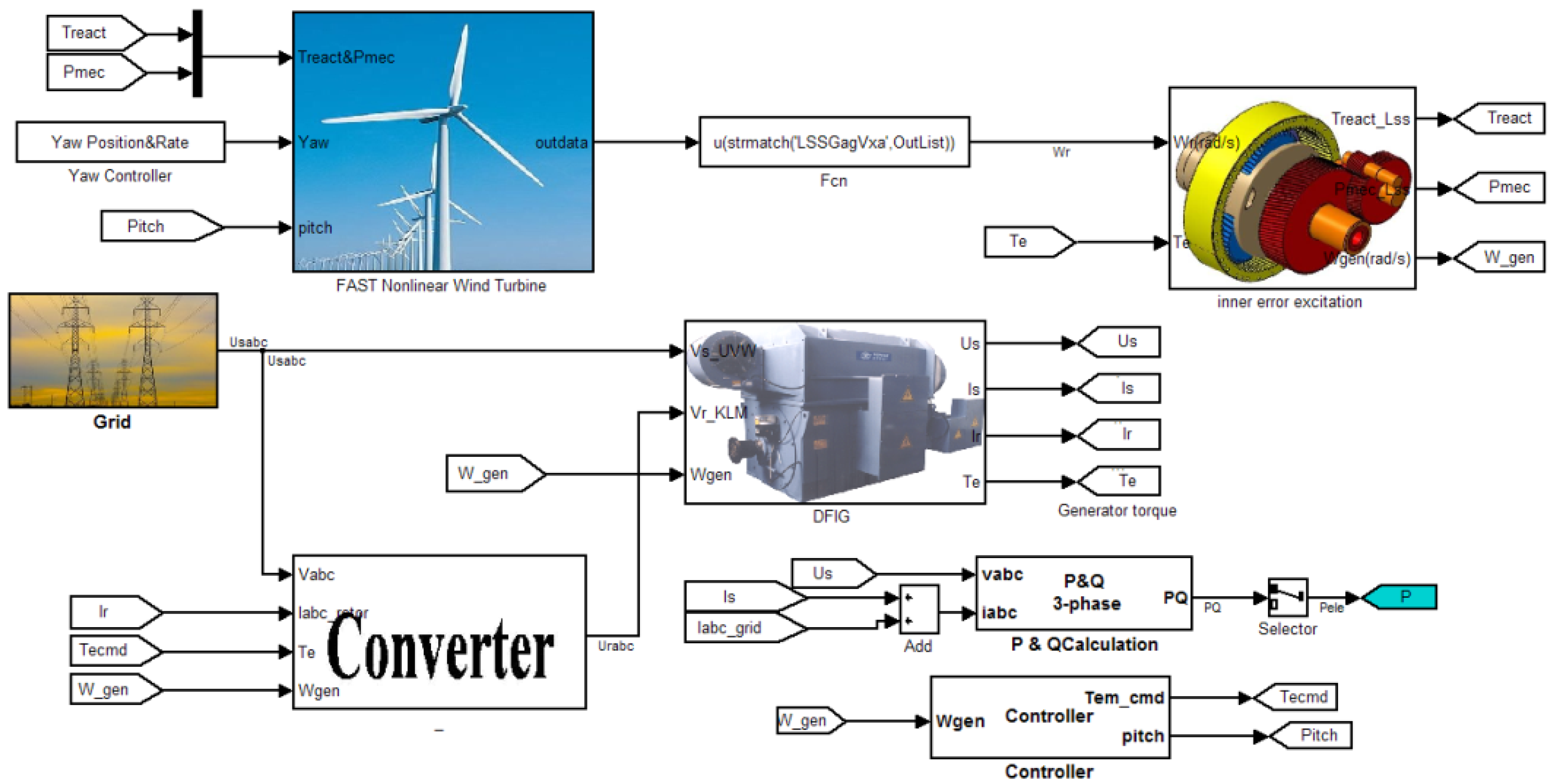
2.3. Model Integration

The two-mass drive train model in FAST is reduced to a single-mass model by deactivating DOF. Furthermore, gearbox ratio and generator inertia are set to unity and zero, respectively. In this way, turbine rotor and tower can be integrated into the subsystem model in MATLAB. Figure 4 shows the Simulink model of the complete system. Turbine rotor speed is transmitted to the gearbox. The reaction torque on LSS and mechanical power are then calculated and fed back to FAST. The DFIG rotor is connected to the grid through converter while the stator is connected directly. Tecmd is obtained by a look-up table and pitch regulation is activated according to the generator speed [17].
Figure 4. Integrated model in MATLAB.
Energies 08 11452 g004

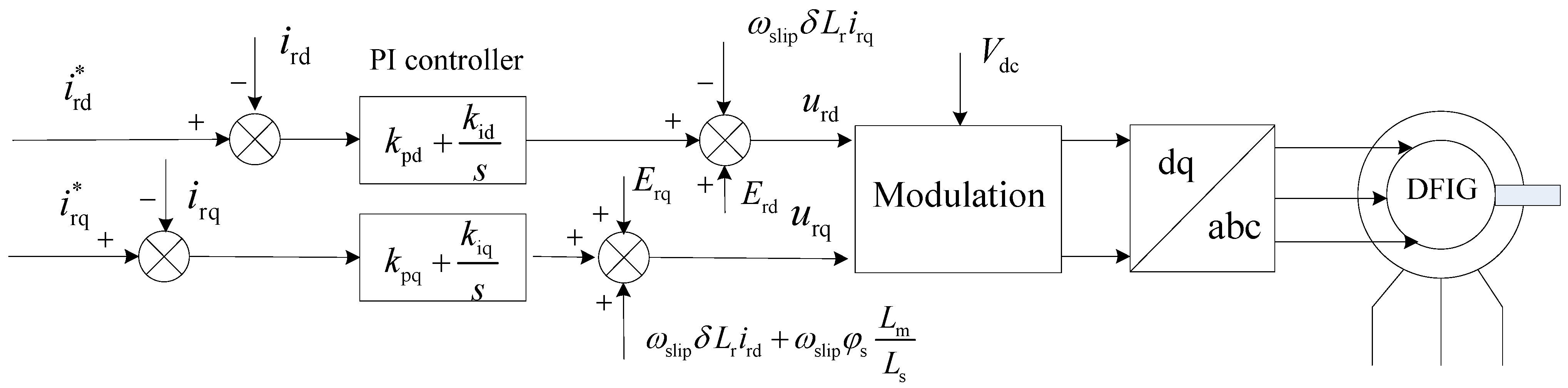
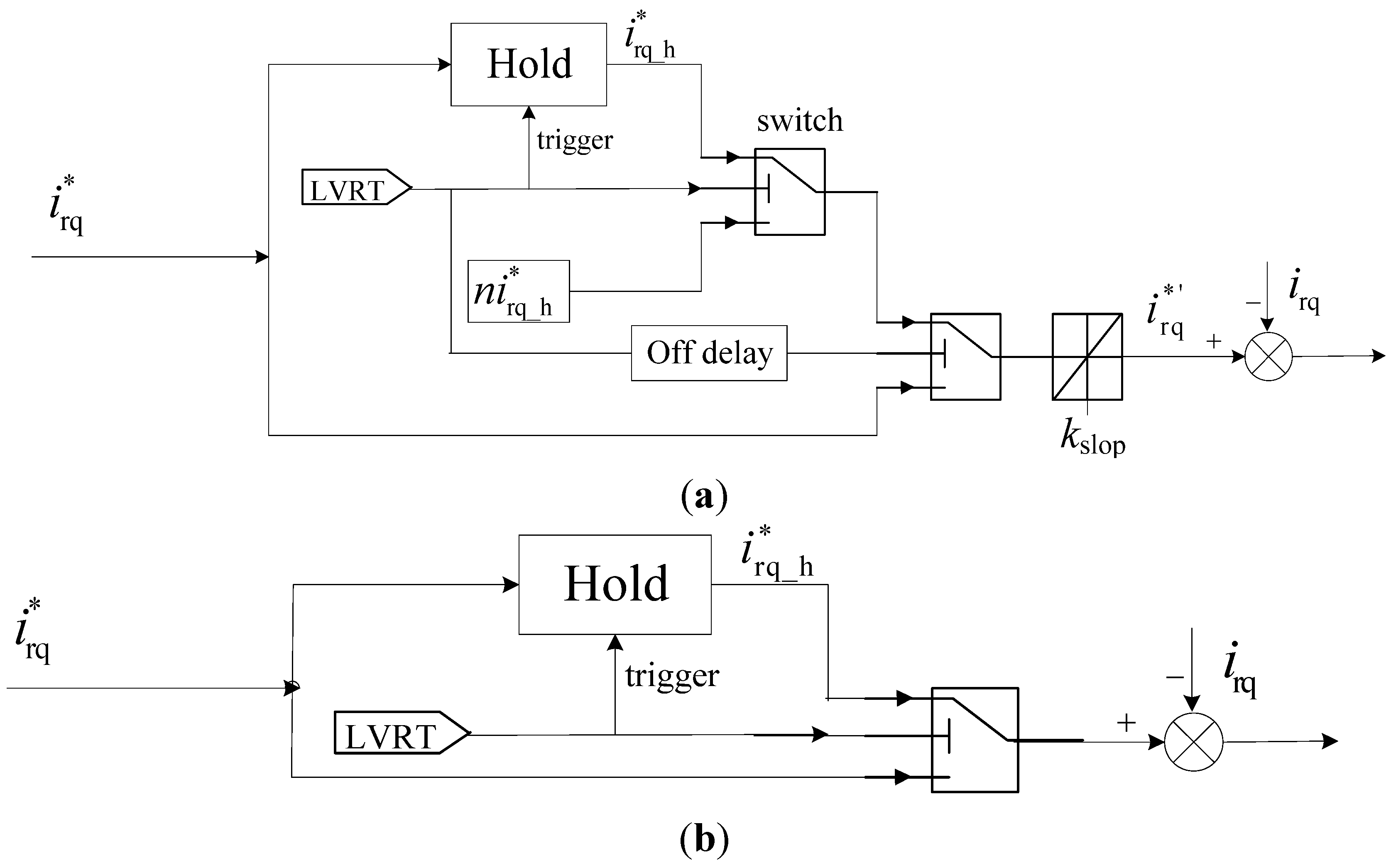
3. Rotor Side Converter (RSC) Control during Voltage Dip

Power system operators have set specific requirements in order to connect wind turbines to the grid when the voltage at the point of common connection (PCC) suffers a significant drop in a very short time. The requirements in individual countries might be different [18,19,20]. The wind turbine needs to keep operating for 625 ms when the voltage at PCC dips to 20% of the rated value in China [21], as shown in Figure 5. Only when the voltage goes below the curve, wind turbines are allowed to disconnect. After the faults are cleared, active power is required to increase at the rate of at least 0.1 pu/s. These requirements are considered for the operation of single wind turbine in the study cases.
Specific control strategies are essential to avoid over-voltage and over-current scenarios during LVRT. Particularly, when the voltage dips asymmetrically, negative sequence voltages arise causing negative sequence currents which produce pulsations in torque, active and reactive power. In order to assess the impact on drive train in the worst cases, approaches for reducing the negative sequence effect are ignored. Additionally, crowbar protection and chopper circuit for dc-bus are ignored in the model.
The voltage dip is roughly divided into the deeper and lower dips without considering the electrical constraints in this paper. When the voltage dips deeper, the different rising speed of power recovery is focused and when the voltage dips slower, the controller with and without considering over-current in practical are compared. These control strategies implemented in MATLAB are described as follows.
Figure 5. Ride-through fault capability curve required by Chinese grid code. PCC: point of common connection.
Energies 08 11452 g005

3.1. Deeper Voltage Dip

In order to prevent the rotor over-current that is caused by the excess electrical power not transmitted to the grid, the output of active power during voltage dip should be decreased and this can be achieved by the control of decoupled rotor current irq. The stator active power is shown as:
P s = 3 2 L m L s U sq i rq
The diagram of the control strategy is described in Figure 6a. The reference value i*rq will be hold once the LVRT signal is detected and the hold value is represented by i*rq_h. It leads to the active power dip during the hold time as well as the electromagnetic torque. Then i*rq_h will be decreased n times once the voltage recovers. The factor n is a calculated ratio of positive voltage after and before dip. In this way, the final reference value i*rq will be increase at a certain rate (kslop) after the voltage recovery. The certain rate is determined mainly from the standpoint of electric devices and power system. However, the wind turbine dynamic response in the LVRT situation with the immediate power recovery (without the kslop) is analyzed in [7,10]. This diagram of control is described in Figure 6b. For a clearer description, Figure 7 shows the evolution of i*rq along the time.
Figure 6. Diagram of converter control during deeper voltage dip: (a) power recovery at a certain speed; and (b) immediate power recovery.
Energies 08 11452 g006
Figure 7. Evolution of i*rq along the time during deeper voltage dip: (a) power recovery at a certain speed; and (b) immediate power recovery.
Energies 08 11452 g007

3.2. Lower Voltage Dip

If the grid voltage dips with lower amplitude, the reference value of rotor current i*rq will depend on the overload capacity of RSC during the dip time. The control strategies might be the same as shown in Figure 6 for a weaker converter and then the continuous over-current will be prevented. RSC can also be controlled as in the ideal state and the behavior of DFIG was analyzed in [8,22].

4. Study Cases and Simulation Results

In order to avoid the impact on the electrical network caused by power loss, wind turbine generation systems are required to increase the power as soon as possible after the voltage recovery. When a two-phase or single-phase fault occurs, the main control object of RSC is to eliminate the negative sequence in the rotor current and obtain a balanced stator current for the safe operation of RSC and DFIG, so less attention was previously paid to the effect of the converter control strategies on the drive train. In addition, the mechanical design for wind turbines also has little consideration for DFIG excitation. In the cases studied below, the interaction between the electrical control and mechanical components during voltage dip is analyzed. The dynamic load on HSS is highlighted because it is vulnerable in practice.

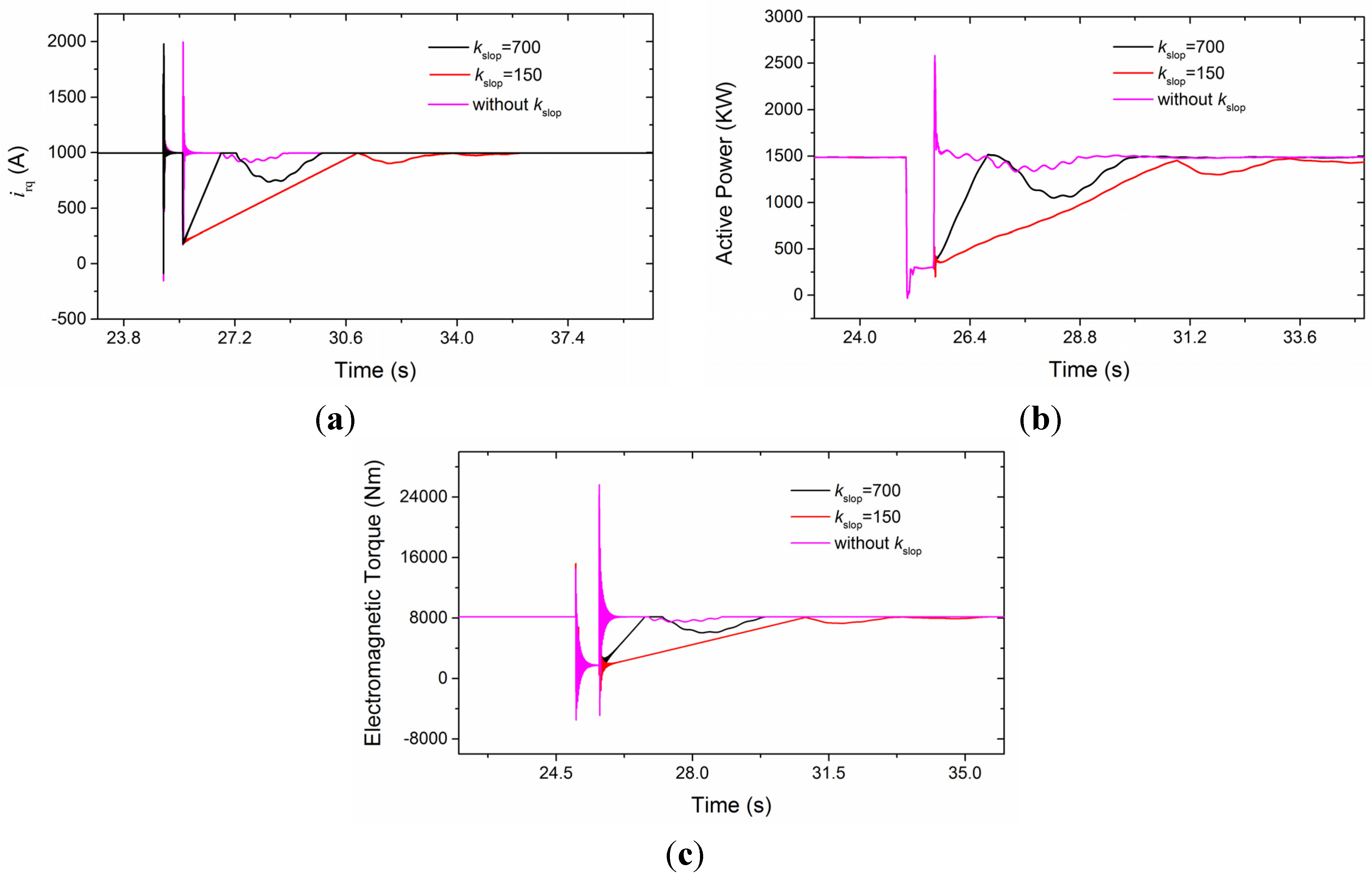
4.1. Rising Speed Effect of Power Recovery

In the simulation, three-phase voltage dips to 0.2 pu at 25 s and lasts for 600 ms. The wind is set to a constant value of 12 m/s, because a strong wind can lead to a greater impact on wind turbines during grid faults [10]. It should be noted that electrical constraints and protections are ignored for obtaining the electromagnetic torque with large oscillation. The GSC works in an ideal state. In this way, the impact on the drive train can be considered as in the worst situation.
The dynamic response comparisons of electrical variables with the different rising speed of power recovery are depicted in Figure 8.
Figure 8. Dynamic response of electrical variables with the different rising speed of active power recovery: (a) decoupled rotor current irq; (b) total active power of wind turbine; and (c) electromagnetic torque.
Energies 08 11452 g008
In Figure 8a, it can be seen that the decoupled rotor currents have the same response before the voltage recovery. The spike due to the sudden voltage drop is obvious and it appears again when the voltage recovers for the control without kslop. However, it can be avoided if the current rises at a certain speed. The current transient can also be reflected in the active power, especially for the immediate recovery of power, shown in Figure 8b. Thanks to the hold current during the voltage dip, the total active power is decreased. The current drops to a certain value at the moment of voltage recovery for increasing the active power, and the rising rate is 157 kW/s when the kslop equals 150. The overshoot of pitch regulation leads to a sunken power around 28 s with the faster rising slope (kslop = 700). The similar response is presented in electromagnetic torque, as shown in Figure 8c.
The dynamic responses of mechanical variables are shown in Figure 9.
Figure 9. Dynamic responses of mechanical variables with the different rising speed of active power recovery. (a) HSS torque; (b) torsional oscillation without kslop in frequency domain during 25–33 s; (c) acceleration of tower side-side mode; (d) acceleration of side-side mode without kslop in frequency domain during 25–33 s; (e) pitch angle; and (f) generator speed.
Energies 08 11452 g009
The aerodynamic torque and the generator torque are applied to the two ends of the drive train, resulting in a torsion of the shaft. During the voltage dip, as the electrical torque is significantly reduced, the drive train acts like a torsion spring that gets untwisted [7], so the difference of angular speed at the two ends of the drive train will experience large oscillations. According to the Equation (2), an instant torsional oscillation will be reflected on the shaft torque, as depicted in Figure 9a. Active power recovers at once leading to the greatest impact on HSS, whereas the oscillation amplitude will be significantly reduced when a certain slope is applied. And the slower the power increases, the smaller the oscillation will be. The largest amplitude of oscillation for the smallest kslop (150) happens at the lower torque. This oscillation frequency for the control without kslop during 25–33 s is shown in Figure 9b. It indicates that the lower mode eigenfrequency of drive train is easier to excite. It is different from the second mode in Table 2 because of the flexible turbine rotor considered in FAST. Active power and generator speed follow the oscillation patterns with the oscillation frequency. The rate of oscillation decay depends on the shaft torsional damping. It should be pointed out that the dynamic response on shaft torques under this condition is much different from step wind excitation. Because of the huge rotor mechanical inertia, the step wind cannot increase the torque abruptly.
Torsional oscillation is closely coupled with the tower side-side mode, and the equations of motion can be found in [23]. The impact due to the voltage dip can be transmitted to the tower and reflected on the acceleration which is harmful for the yaw bearing. In Figure 9c, the peak value of acceleration without the kslop is almost twice that with the kslop, and the kslop with a smaller value leads to less effect on the first side-side mode (0.4 Hz) oscillation of the tower, which can be seen clearly during 32–40 s. Except for the eigenfrequency of the first mode excited, the second eigenfrequency of 3 Hz and torsional oscillation frequency, shown in Figure 9d, can also be found. The decay of oscillation depends on the damping ratio of tower side-side mode—1.5 is used in this paper.
Pitch regulation in an emergency can prevent the over-speed, and the pitch angle increases at the maximum rate of 10°/s when power recovers with kslop for this model, as shown in Figure 9e. It can be seen in Figure 9f that generator speed return to the rated value is much slower with the smaller kslop, however, it probably does not threaten the wind turbine by over-speed compared with the faster power rise. The slower rising speed of power recovery is a better choice for the wind turbine fatigue, if it is allowed by the electrical requirements.

4.2. Effect of Different Converter Control during Small Voltage Dip

The small voltage dip usually can not result in the action of crowbar protection, whereas the over-current threatens the operation of electrical devices. As shown in Figure 10, voltage symmetrically dips to 0.9 pu and a comparison of the effect of different converter control strategies is performed.
A continuous over-current is caused for the RSC controlled as in ideal state, which maintains the electromagnetic torque near the rated value and the oscillation with frequency of 50 Hz is the result of transients of stator flux. The hold rotor current leads to a sag in electromagnetic torque, shown in Figure 10b. kslop with the value of 700 is used in this and the next study case.
Figure 10c describes the impact on HSS with and without torque sag, and the fluctuation in normal operation is mainly caused by the wind shear and tower shadow effect. It can be seen that the control without torque sag has a small influence on HSS, but the impact is much greater if the electromagnetic torque is decreased suddenly. The HSS torque can dip approximately to 87% of the rated value in an instant and the gears will also experience torque sag. If the impact is frequent or severer, it might lead to damage to the oil film between gear teeth and result in wear and tear on the tooth surface. The larger oscillation on the acceleration of tower side-side mode is excited, as depicted in Figure 10d. Consequently, a tough converter that can sustain the continuous over-current without torque sag during small voltage dip is favorable for the mechanical loads.
Figure 10. Comparisons of variables under different converter control strategies during small voltage dip: (a) decoupled rotor current; (b) electromagnetic torque; (c) HSS torque; and (d) acceleration of tower side-side mode.
Energies 08 11452 g010

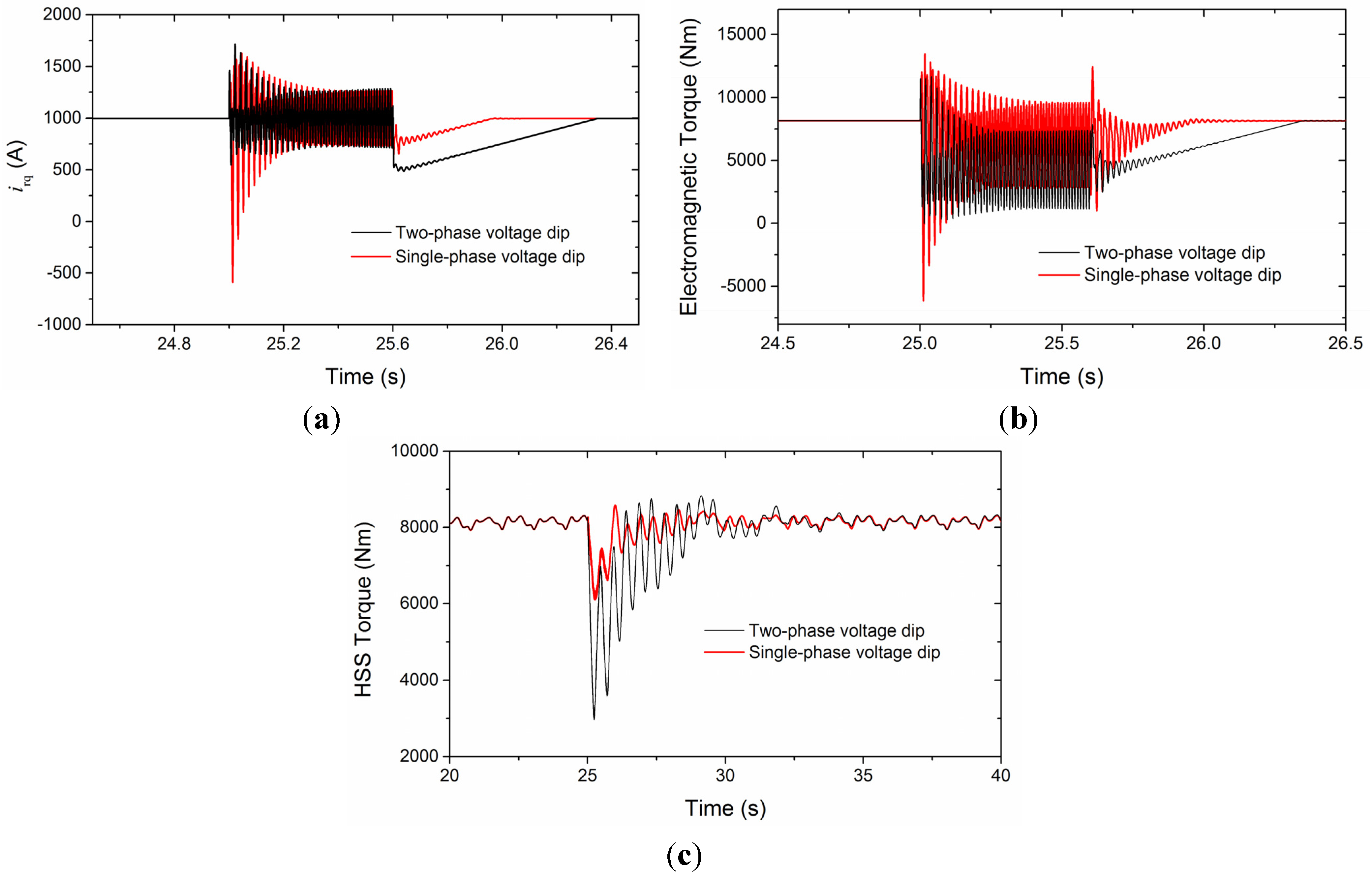
4.3. Effect of Unbalanced Voltage Dip

Figure 11 shows the evolutions of variables under single-phase and two-phase voltage dip conditions. 20% of the rated value is retained for the dipping phase. Without consideration of a negative sequence in the RSC control, the larger amplitude oscillation with the frequency of 100 Hz is excited in irq. And the transient of attenuating oscillation with the frequency of 50 Hz for single-phase voltage dip is more obvious than the two-phase voltage dip in this work.
These transients lead to the response of electromagnetic torque, shown in Figure 11b. However, the frequency of 100 Hz is not reflected apparently on the HSS torque due to the torque sag in a very short time. Comparing with Figure 9a, the maximum HSS torque excursion happens when the three-phase voltage dips and the effect of the single-phase voltage dip is the smallest. The transmitted loads on HSS might be amplified if drive train eigenfrequency is close to the 100 Hz under unbalanced voltage conditions.
Figure 11. Evolutions of variables during single-phase and two-phase voltage dip: (a) decoupled rotor current; (b) electromagnetic torque; and (c) HSS torque.
Energies 08 11452 g011
As described in Table 2, the second eigenfrequency mainly depends on the flexibility of the rotor and LSS with the invariant inertias while the higher eigenfrequencies are dominated by the gearbox. In practice, the coupling is a connection between the output shaft of the gearbox and generator and used for the misalignment of shafts, but it reduces the effective stiffness of HSS in the drive train model [8]. Figure 12 shows the relationship of the three eigenfrequencies with HSS stiffness and the vertical coordinate is logarithmic. KHSS should be set to 1 × 10⁷ Nm/rad, if the coupling is not taken into account. When KHSS equals to 0.9 × 10⁶ Nm/rad, resonance might be excited by the electromagnetic torque with 100 Hz oscillation.
Figure 12. Relationship of the eigenfrequencies with HSS stiffness.
Energies 08 11452 g012
Figure 13 shows the resonance on HSS torque with and without the torque sag control when a two-phase voltage dips to 0.9 pu at 18 s. In this situation, the voltage unbalance factor is 3.5%, and electromagnetic torque increases immediately (without kslop) as seen in Figure 13a. The resonance in both control strategies has a significant effect on the fatigue life of the gearbox. The “Rainflow Counting” method [24] is used for evaluating the performance of the two control strategies on gearbox fatigue. The results for the resonance situation are presented in Table 3. The rainflow cycle counts in large amplitude oscillation for the control with torque sag are less than without, but the contrary occurs with a small amplitude. It should be noted that the number of cycles to failure reduce by around 1/50 times when the stress cycle amplitude increases three times [24]. Therefore, an increased number of low amplitude stress cycles can be tolerated, if accompanied by a significant decrease in the number of cycles in the high magnitude region. The control with torque sag is better for the gearbox under the condition of large oscillation torque caused by the unbalanced voltage dip.
Figure 13. Resonance effect on HSS torque under small unbalanced voltage dip: (a) control with generator torque sag; and (b) control without generator torque sag.
Energies 08 11452 g013
Table 3. Rainflow cycle counts.
Amplitude of torque oscillation (Nm)With torque sagWithout torque sag
12022
20011
280300
41011
550115
590135
In practice, the voltages of a MV distribution network always exhibit a certain amount of unbalance, mainly due to the unequal distribution of consumer loads among three phases [6]. This will lead to a steady state 100 Hz oscillating torque component, the amplitude of which might exert severe influence on the fatigue life of the gearbox. Under this condition, decreasing the generator torque with small amplitude and increasing the pitch angle accordingly could be beneficial for the gearbox. Another electric disturbance to the drive train is the grid voltage distortion of 5-order and 7-order harmonics, which will evolve to the oscillation component at 300 Hz in the electromagnetic torque. However, its impact on HSS is small and it is not easy to excite the higher order mode of drive train within the voltage distortion grid allowed.

5. Conclusions

Symmetrical and unsymmetrical faults have been simulated in this paper, which focuses on the impact on the drive train due to the different RSC control strategies under grid fault conditions. The simulation results provide a clear indication of the effects of rising speed of power recovery, torque sag and drive train resonance from the mechanical point of view.
For the symmetrical faults, no matter what the rising speed of power recovery is, an impact will be exerted on the drive train at the moment of voltage dip and then transmitted to the tower. However, the slower power rising leads to a reduction in large amplitude oscillation. Detrimental influence on the gearbox can be avoided during small voltage dips without torque sag, if over-current and over-voltage can be handled.
Among the faults, maximum torque transients are caused by symmetrical voltage dips. In the case of unbalanced faults, a sustained double power frequency (100 Hz) oscillation arises, which will provoke resonance in the drive train if the mode frequency of the mechanical structure is also around 100 Hz. The resonance will threaten gearbox fatigue life, especially for high-speed shafts, but it can be mitigated by decreasing the generator torque to a small amplitude. Furthermore, the multiple of power frequency should be considered in the mechanical structure.

Acknowledgments

This work was financially supported by the National Natural Science Foundation of China under Award No. 51477007.

Author Contributions

All the authors contributed equally to the full electromechanical model, numerical simulations and results interpretation. All co-authors performed editing and reviewing of the paper.

Conflicts of Interest

The authors declare no conflict of interest.

Appendix

Table A1. Generator and control parameters. RSC: rotor side converter; GSC: grid side converter.
Generator ParametersValue
Rs, Rr (mΩ)7.747, 6.881
Ls, Lr (mH)0.226, 0.278
Lm (mH)8.463
Pole pairs2
Converter Control ParametersValue
RSC kpd, kid0.1, 10
RSC kpq, kiq8, 100
GSC kpd, kid1, 10
GSC kpq, kiq1, 10
Pitch control parametersValue
kp-pitch, ki-pitch1, 0.3
Time delay due to pitch actuator (s)0.2
Maximum rate of pitch actuation (deg/s)10
kpd, kid, kpq, kiq are the PI controller parameters in the decoupled d-q current control loop of RSC and GSC; kp-pitch and ki-pitch are the parameters in PI controller which regulates the rotor speed with the output of pitch angle.

References

  1. Chen, W.J.; Blaabjerg, F.; Zhu, N.; Chen, M.; Xu, D. Doubly fed induction generator based wind turbine systems subject to recurring grid faults. In Proceedings of the IEEE Applied Power Electronics Conference and Exposition-APEC 2014, Fort Worth, TX, USA, 16–20 March 2014.
  2. Blaabjerg, F.; Liserre, M.; Ma, K. Power electronics converters for wind turbine systems. IEEE Trans. Ind. Appl. 2012, 48, 708–719. [Google Scholar] [CrossRef]
  3. Trilla, L.; Gomis-Bellmunt, O.; Junyent-Ferre, A.; Mata, M.; Sanchez Navarro, J.; Sudria-Andreu, A. Modeling and validation of DFIG 3-MW wind turbine using field test data of balanced and unbalanced voltage sags. IEEE Trans. Sustain. Energy 2011, 2, 509–519. [Google Scholar] [CrossRef]
  4. Kiani, M.; Lee, W.J. Effects of voltage unbalance and system harmonics on the performance of doubly fed induction wind generators. IEEE Trans. Ind. Appl. 2010, 46, 562–568. [Google Scholar] [CrossRef]
  5. Xu, L.; Wang, Y. Dynamic modeling and control of DFIG-based wind turbines under unbalanced network conditions. IEEE Trans. Power Syst. 2007, 22, 314–323. [Google Scholar] [CrossRef]
  6. Papathanassiou, S.A.; Papadopoulos, M.P. Mechanical stresses in fixed-speed wind turbines due to network disturbances. IEEE Trans. Energy Convers. 2001, 16, 361–367. [Google Scholar] [CrossRef]
  7. Buendia, F.J.; Vigueras-Rodriguez, A.; Gomez-Lazaro, E.; Fuentes, J.A.; Molina-Garcia, A. Validation of a mechanical model for fault ride-through: Application to a Gamesa G52 commercial wind turbine. IEEE Trans. Energy Convers. 2013, 28, 707–715. [Google Scholar] [CrossRef]
  8. Girsang, I.P.; Dhupia, J.S.; Muljadi, E.; Singh, M.; Pao, L.Y. Gearbox and drivetrain models to study dynamic effects of modern wind turbines. IEEE Trans. Ind. Appl. 2014, 50, 874–881. [Google Scholar] [CrossRef]
  9. The MathWorks, Inc. Simscape User’s Guide. Available online: http://www.mathworks.cn/help/pdf_doc/physmod/simscape/simscape_ug.pdf (accessed on 10 July 2015).
  10. Fadaeinedjad, R.; Moallem, M.; Moschopoulos, G. Simulation of a wind turbine with doubly fed induction generator by FAST and Simulink. IEEE Trans. Energy Convers. 2008, 23, 690–700. [Google Scholar] [CrossRef]
  11. Jonkman, J.M.; Buhl, M.L., Jr. FAST User’s Guide. Available online: https://nwtc.nrel.gov/system/files/FAST.pdf (accessed on 10 July 2015).
  12. Miao, F.L.; Shi, H.S.; Zhang, X.Q. Modelling of wind turbines coupled in multi-domain and dynamic response analysis. Proc. Chin. Soc. Electr. Eng. 2015, 35, 1704–1712. (In Chinese) [Google Scholar]
  13. Pedersen, R. Dynamic Modeling of Wind Turbine Gearboxes and Experimental Validation. Ph.D. Thesis, Technical University of Denmark, Copenhagan, Denmark, 2010. [Google Scholar]
  14. Peeters, J. Simualtion of Dynamic Drive Train Loads in a Wind Turbine. Ph.D. Thesis, Katholieke University Leuven, Leuven, Belgium, 2006. [Google Scholar]
  15. Lei, T.; Barnes, M.; Ozakturk, M. Doubly-fed induction generator wind turbine modelling for detailed electromagnetic system studies. IET Renew. Power Gener. 2013, 7, 180–189. [Google Scholar] [CrossRef]
  16. Wang, Y.; Wu, Q.W.; Xu, H.H.; Guo, Q.L.; Sun, H.B. Fast coordinated control of DFIG wind turbine generators for low and high voltage ride-through. Energies 2014, 7, 4140–4156. [Google Scholar] [CrossRef] [Green Version]
  17. You, R.; Barahona, B.; Chai, J.Y.; Cutululis, N.A. A novel wind turbine concept based on an electromagnetic coupler and the study of its fault ride-through capability. Energies 2013, 6, 6120–6136. [Google Scholar] [CrossRef]
  18. Morren, J.; de Haan, S.W.H. Ride through of wind turbines with doubly-fed induction generator during a voltage dip. IEEE Trans. Energy Convers. 2005, 20, 435–441. [Google Scholar] [CrossRef]
  19. Mendes, V.F.; de Sousa, C.V.; Silva, S.R.; Rabelo, B.; Krauss, S.; Hofmann, W. Behavior of doubly-fed induction generator during symmetrical voltage dips-experimental results. In Proceedings of the 2010 IEEE International Symposium on Industrial Electronics (ISIE), Bari, Italy, 4–7 July 2010.
  20. Erlich, I.; Wrede, H.; Feltes, C. Dynamic behavior of DFIG-Based wind turbines during grid faults. In Proceedings of the Power Conversion Conference (2007 PCC’07), Nagoya, Japan, 2–5 April 2007.
  21. He, Y.K.; Hu, J.B. Several hot-spot issues associated with the grid-connected operations of wind turbine driven doubly fed induction generators. Proc. Chin. Soc. Electr. Eng. 2012, 32, 1–15. (In Chinese) [Google Scholar]
  22. Hu, J.B.; He, Y.K. DFIG wind generation systems operating with limited converter rating considered under unbalanced network conditions—Analysis and control design. Renew. Energy 2011, 36, 829–847. [Google Scholar] [CrossRef]
  23. Zhang, Z.L.; Nielsen, S.R.K.; Blaabjerg, F.; Zhou, D. Dynamics and control of lateral tower vibrations in offshore wind turbine by means of active generator torque. Energies 2014, 7, 7746–7772. [Google Scholar] [CrossRef]
  24. Dixit, A.; Suryanarayanan, S. Towards pitch-scheduled drive train damping in variable-speed, horizontal-axis large wind turbines. In Proceedings of the 44th IEEE Conference on Decision and Control and the European Control Conference, Seville, Spain, 12–15 December 2005.

