1. Introduction
With the problems of air pollution and energy consumption getting more and more concerns, the traditional vehicles with internal combustion engine (ICE) will be probably eliminated in future transportation because they consume fuel derived from non-renewable resources and release exhaust gas. However, electric vehicles (EVs) are rapidly developed during recent decades due to the advantages of energy-saving, non-emission and low noise pollution [
1,
2]. EVs have the potential to provide a perfect solution to energy security and environmental impacts in the future. Especially, if they can be powered by electrical energy generated from renewable sources, such as wind, solar,
etc., they will not need extra petroleum.
As the key part of EVs, different types of traction machines are tried to be used in EVs [
3,
4,
5,
6,
7,
8]. Axial flux permanent-magnet synchronous machines (PMSMs) are becoming more and more attractive in many propulsion applications due to the advantages of high efficiency, power factor and power density [
9,
10,
11,
12,
13,
14,
15,
16]. Undoubtedly, they are also very suitable to propel EVs [
17,
18,
19]. When the axial-flux PMSM drives the EV, it requires a higher torque at low speed and a lower torque at high speed, which implies that the axial-flux PMSM needs a fairly wide field weakening range.
When the PMSM operates normally, neglecting the little voltage on the armature resistance, the voltage Equation of the PMSM can be expressed as [
20]
where
ulim is the supplied limit voltage, ω is the electrical speed,
Ld and
Lq are the
d- and
q-axis inductances,
id and
iq are the
d- and
q-axis current,
ψf is the flux linkage produced by PM.
Constant torque control is adopted below base speed and the voltage will increase with the speed increasing. However, field weakening is needed above base speed where the back electromotive force (EMF) equals the supplied limit voltage. As for normal PMSM, ψf produced by PM is fixed. Thus, based on Equation (1), traditional electrical method, i.e. increasing the d-axis demagnetizing current and decreasing the q-axis current, is usually adopted to improve the operating speed range for PMSM.
However, because of the disk structure of axial flux PMSM, most axial flux machines adopt surface-mounted permanent magnets (PMs) and have large air gaps, which result in small d- and q-axis inductances. This makes the field weakening more difficult to execute for wide range operation by using traditional electrical methods.
In order to improve the wide speed range of axial flux PMSM, various special field-weakening methods are proposed and researched [
21,
22,
23,
24,
25,
26,
27,
28,
29,
30]. In [
21], the rotor pole of the machine adopts a combination of a rare earth magnet (neodymium–iron–bore) and soft laminated iron to reduce the total
d-axis reluctance. So the field-weakening characteristic is obtained by injecting a relatively small negative d-axis current. The axial flux PM machine in [
22] adopts fractional-slot winding and additional cores enclosing end windings to increase the inductance and then the field weakening capability. In [
23,
24], a hybrid dual-rotor–single-stator axial machine with a DC field coil located on the stator and a rotor made of alternate PMs and iron teeth is proposed to fulfill a reasonable range of field weakening. This technique allows an easy control of the axial gap flux with DC field current but without any negative effects of current injection. In addition, mechanical methods of adjusting the air-gap field are also popular in axial flux PM machine. In [
25], an axial-flux permanent magnet (AFPM) machine with two rotors and one stator regulates the flux linkage through displacement of the two rotors by mechanical solutions. Constant power generation is thus achieved with very inexpensive devices. Changing the air gap of the axial flux PM machine by mechanical method is another way to fulfill the field weakening [
26,
27,
28]. Early in 2001, [
29] proposed an axial flux PM machine with radially movable PMs to weaken the air gap flux. But there was no theoretical research results showing the effect of this structure. Considering the speed requirement for the machine used for EVs, the axial flux PMSM with radially sliding PMs adopting mechanical device similar to the structure described in [
29] will be investigated comprehensively in this paper.
Firstly, the field weakening principle and the structure of this kind of axial flux PMSM with radially sliding PMs are introduced and analyzed. Secondly, the influences of radially sliding PMs on magnetic characteristics are analyzed and discussed based on 3D finite element method (FEM). Thirdly, the field weakening capabilities by the mechanical method and by electrical method are compared. At last, the forces on the PMs are researched and the hysteretic characteristics caused by the friction of the PMs are investigated.
2. Field Weakening Principle of the Axial Flux PMSM with Radially Sliding PMs
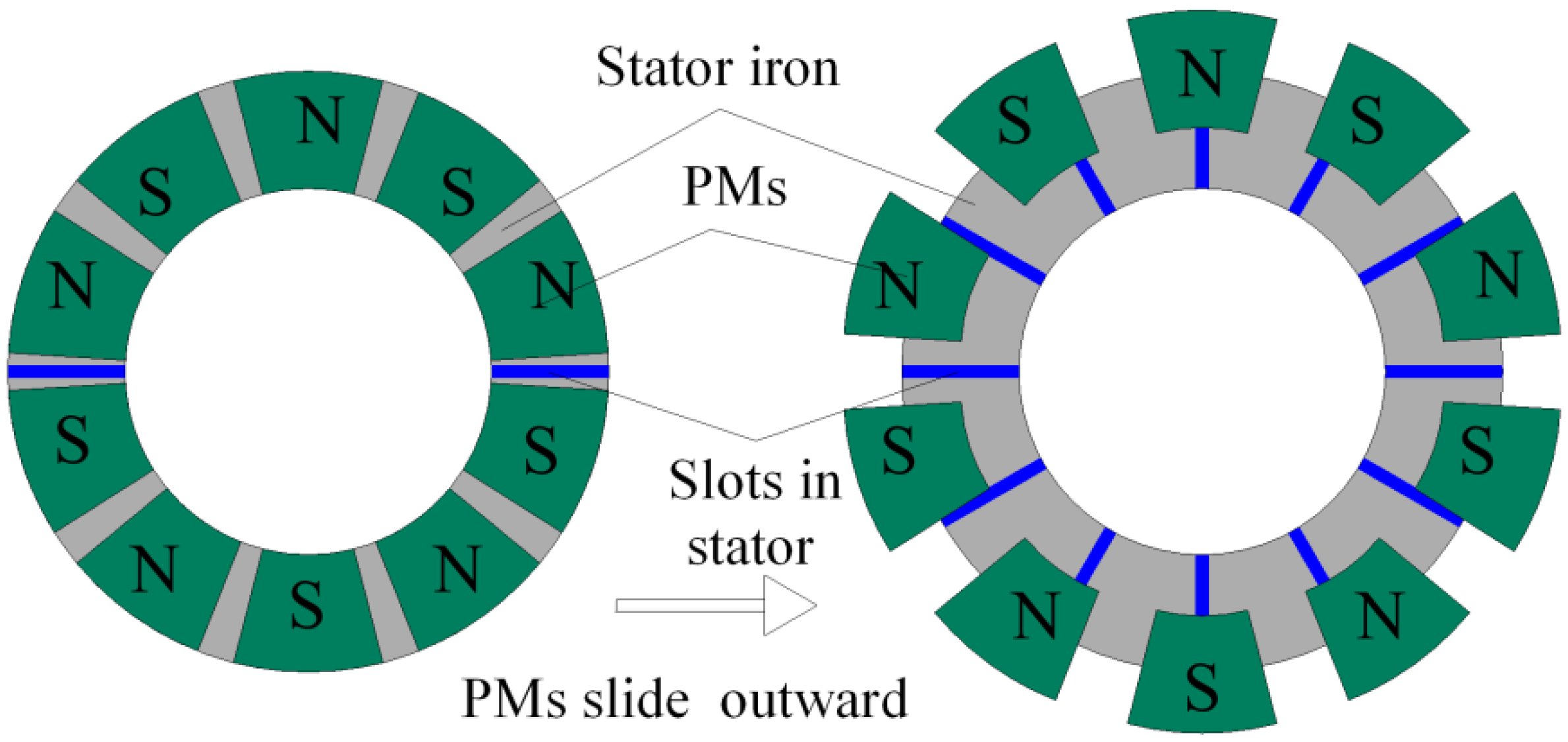
As for normal PMSM, when the rotor is rotating, centrifugal force will be imposed on the PMs mounted on the rotor. The PMs on the rotor are usually fixed by glue, glass fiber tape or directly inserted inside the rotor to overcome the centrifugal force. During a constant speed, if the resultant force provided is smaller than the centrifugal force, the PMs will run away from the circle center. In this paper, centrifugal movement of the PMs will be utilized to make the PMs radially slide away from the circle center when the speed is higher than the base speed. The schematic diagram of the field weakening principle using radially sliding PMs is shown in
Figure 1.
Figure 1.
Schematic diagram of the field weakening principle using radially sliding permanent magnets (PMs).
Figure 1.
Schematic diagram of the field weakening principle using radially sliding permanent magnets (PMs).
When the speed is below the base speed, the PMs stay at the initial position, where the PMs face stator iron directly. When the speed increases to base speed, the PMs are designed to start sliding outward under the centrifugal force. Then the area of PMs facing stator iron decreases. In this case, the main flux produced by the PMs can be expressed as
where
bm is the working point of permanent magnet,
Br is the remnant flux density,
Ameq is the equivalent area under each pole,
σ is the flux leakage coefficient.
The flux linkage
ψf produced by PM can be expressed as
where
N is the turns-in-series per phase of the armature winding,
kw1 is the fundamental winding factor.
Due to the decrease of
, the flux linkage ψf will also decrease. Based on Equation (1), when the limit voltage ulim of the machine is fixed, the speed ω will increase consequentially with flux linkage reducing. This is the field weakening principle using the mechanical method without current adjustment.
3. Structure of the Axial Flux PMSM with Radially Sliding PMs
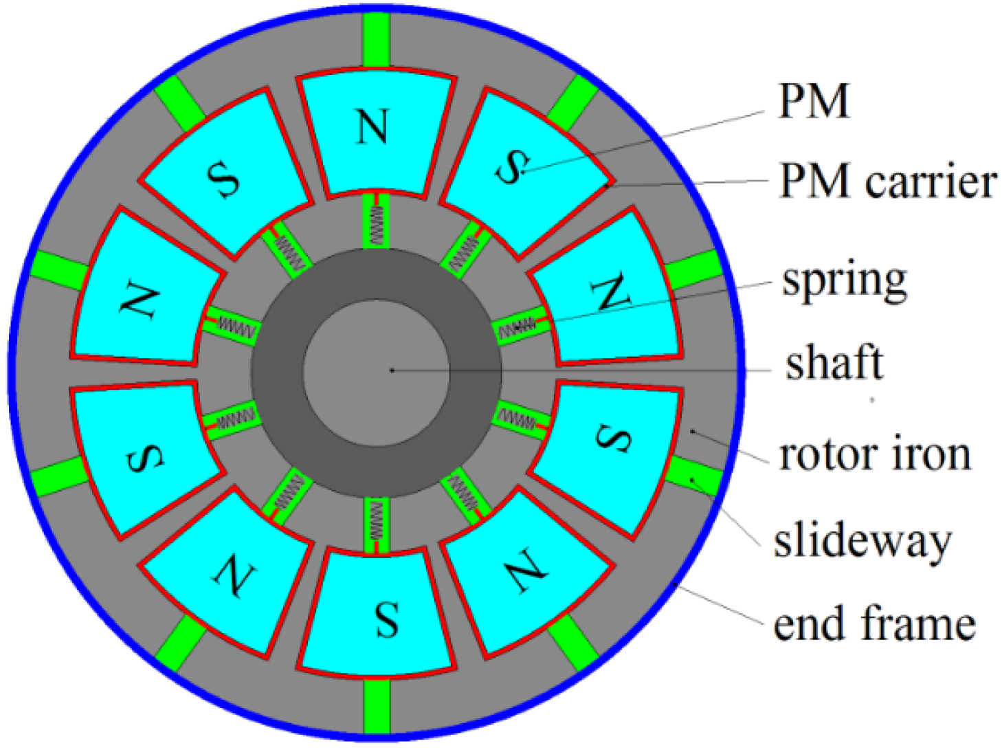
The axial flux PMSM with radially sliding PMs in this paper contains two electromagnetic parts: a conventional disk stator with three-phase windings and a novel disk rotor with radially sliding PMs. The structure of the rotor is much improved to realize the field weakening by moving the sliding PMs in radial direction. As shown in
Figure 2, the novel rotor consists of the rotor core, the sliding PMs, the PM carriers where the PMs are embedded in, the slideways on which the PMs slide, and the spring device to provide the main centripetal force. The main differences between the novel rotor structure and the traditional rotor structure are as follows:
(1) The outer diameter of the new rotor is bigger than that of the traditional rotor. The traditional outer diameter is the same with the PMs outer diameter, while the new outer diameter should be bigger to provide the space for the PMs sliding. In addition, there is an end frame to limit the maximal sliding distance of the PMs.
(2) In order to connect PM with the spring device, PM carriers with spring connecting end are needed to carry the PMs.
(3) Slideways are needed to avoid the PMs diverging from the original radial line under the centrifugal force. The slideway is along with the radial line. The PM is fixed on the slider inside the slideway.
(4) The springs are necessary to provide the main centripetal force when the PMs are rotating. The springs have initial tension load to overcome the centrifugal force under the base speed, because the PMs should not slide under the base speed.
Because the novel rotor has the sliding PMs in radial direction, little field weakening current is needed. And there is almost no risk of demagnetization of the PMs. The field weakening range can be realized by changing the slide distance of the PMs, which raises the potential of the field weakening to a very high level. But what should be noted is that: due to the sliding friction, the radial displacement of the PMs may not be the same for all the PMs in actual operation, which could cause voltage dissymmetry, circulating currents between parallel paths, and bending torque. This risk should be avoided as possible in manufacture. The performances researched in this paper are based on the ideal situations.
Figure 2.
Schematic diagram of the novel rotor with sliding PMs.
Figure 2.
Schematic diagram of the novel rotor with sliding PMs.
4. Investigation of the Electromagnetic Characteristics
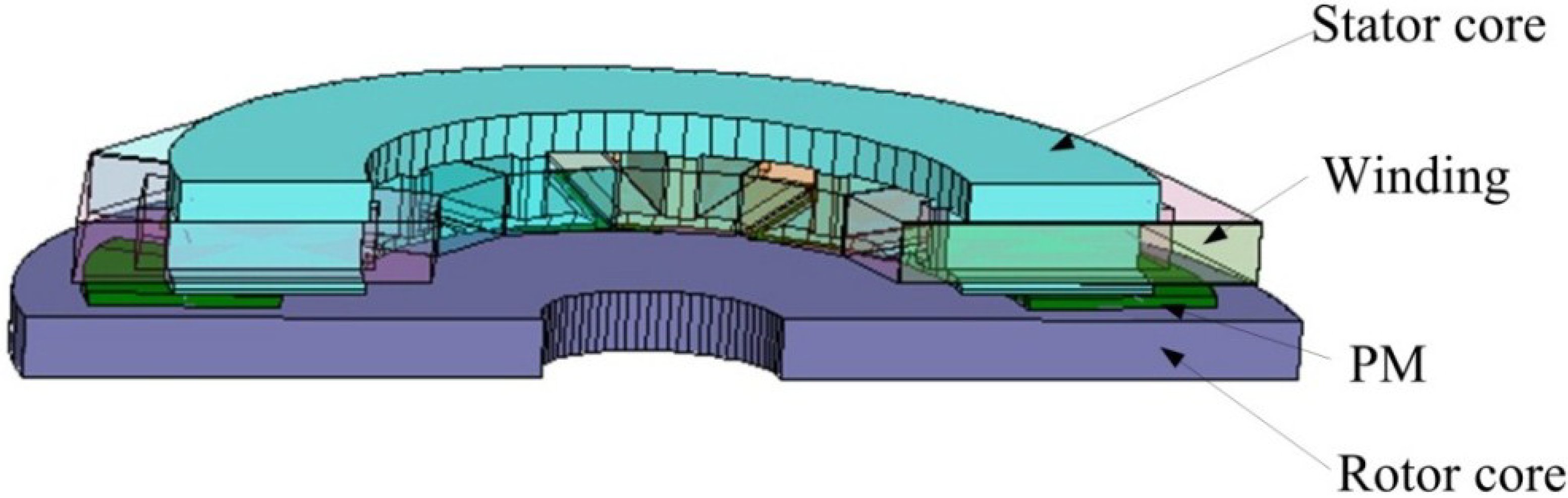
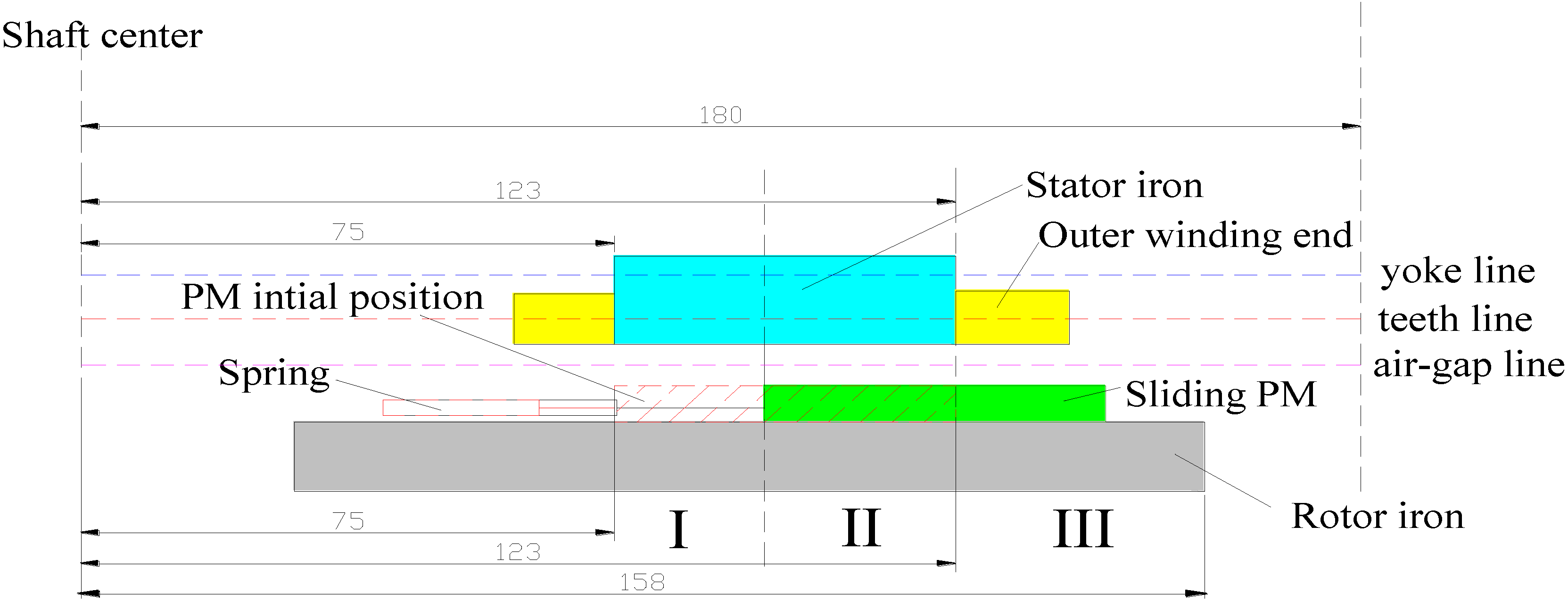
When the machine speed is above the base speed, the centrifugal force becomes bigger than the initial tension load of the springs, which makes the PMs slide in radial direction. The area where the PMs face the stator core will change, which will affect the magnetic field distribution and the electromagnetic performances. In this section the influences of the sliding PMs on the electromagnetic characteristics will be analyzed on the aspects of magnetic field distribution, inductance, magnetic flux linkage of windings and torque. All of these aspects are related to the position of the PMs, but not related to the speed of the machine. The main parameters of the axial flux PMSM investigated are shown in
Table 1. The half and whole 3D FEM models both are adopted in this following simulation. When the performance is calculated in magnetostatic case, such as distribution of field flux density, the whole 3D-FEM model is adopted. When the performance is calculated in transient case, such as torque, the half 3D-FEM model is adopted. The half 3D-FEM model of the axial flux PM machine with PMs sliding outward is shown in
Figure 3. Considering that the effect of slideways and spring is too weak on electromagnetic performance, the slideways are neglected in the 3D FEM model in order to simplify the model and reduce the mesh numbers.
Figure 4 is the cross diagram of radial section of the axial flux PMSM when PMs slide outward. When the PMs slide outward, the machine can be divided into three sections in the radial direction, as shown in
Figure 4. Part I contains stator iron and rotor iron but no PMs. Part II contains stator iron, rotor iron and PMs. Part III contains rotor iron and PMs but no stator iron.
Table 1.
Main initial parameters of axial flux PMSM with radially sliding permanent magnets (PMs).
Table 1.
Main initial parameters of axial flux PMSM with radially sliding permanent magnets (PMs).
| Symbol | Machine Parameter | Values | Unit |
|---|
| Inner diameter of PM | 75 | mm |
| Outer diameter of PM | 123 | mm |
| Inner diameter of stator iron | 75 | mm |
| Outer diameter of stator iron | 123 | mm |
| Outer diameter of rotor iron | 158 | mm |
| Maximal sliding distance | 33 | mm |
| Base speed | 3000 | rpm |
| Rated output torque | 32 | Nm |
| Voltage | 110 | V |
Figure 3.
Half 3D finite-element-method (3D-FEM) model of the axial flux PM machine with PMs sliding outward.
Figure 3.
Half 3D finite-element-method (3D-FEM) model of the axial flux PM machine with PMs sliding outward.
Figure 4.
Cross diagram of radial section of the axial flux permanent-magnet synchronous machine (PMSM) when PMs slide outwards.
Figure 4.
Cross diagram of radial section of the axial flux permanent-magnet synchronous machine (PMSM) when PMs slide outwards.
4.1. Influences on the Magnetic Flux Density Distribution
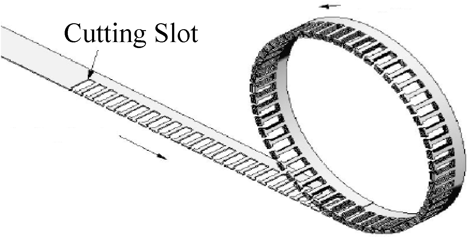
Two kinds of stator meeting the 3D flux characteristics of the axial flux PMSM are compared in this part. One is the stator core with rolled lamination, which can be made with long sheet of steel rolled up and slots cut during the rolling [
31], as illustrated in
Figure 5. In this case, it is easy for the magnetic flux to pass the stator core steel along the axial and circumferential direction. However, it is hard to pass the stator core along radial direction, which is perpendicular to the laminated steel. The other stator is made of soft magnetic composite (SMC). The SMC is made from powder iron material and can be molded to any shape theoretically with a similar process to plastic injection molding [
32,
33]. The stator core with SMC has equal magnetic permeability in every direction. Due to different processing methods, the magnetic flux density distributions of the machines with the two different materials may be different and compared in this part. Considering that the changing law of the flux linkage, inductance and torque will not be influenced by material, only the performances of the machine with SMC are presented in following parts.
Figure 5.
Scheme of rolled lamination [
31].
Figure 5.
Scheme of rolled lamination [
31].
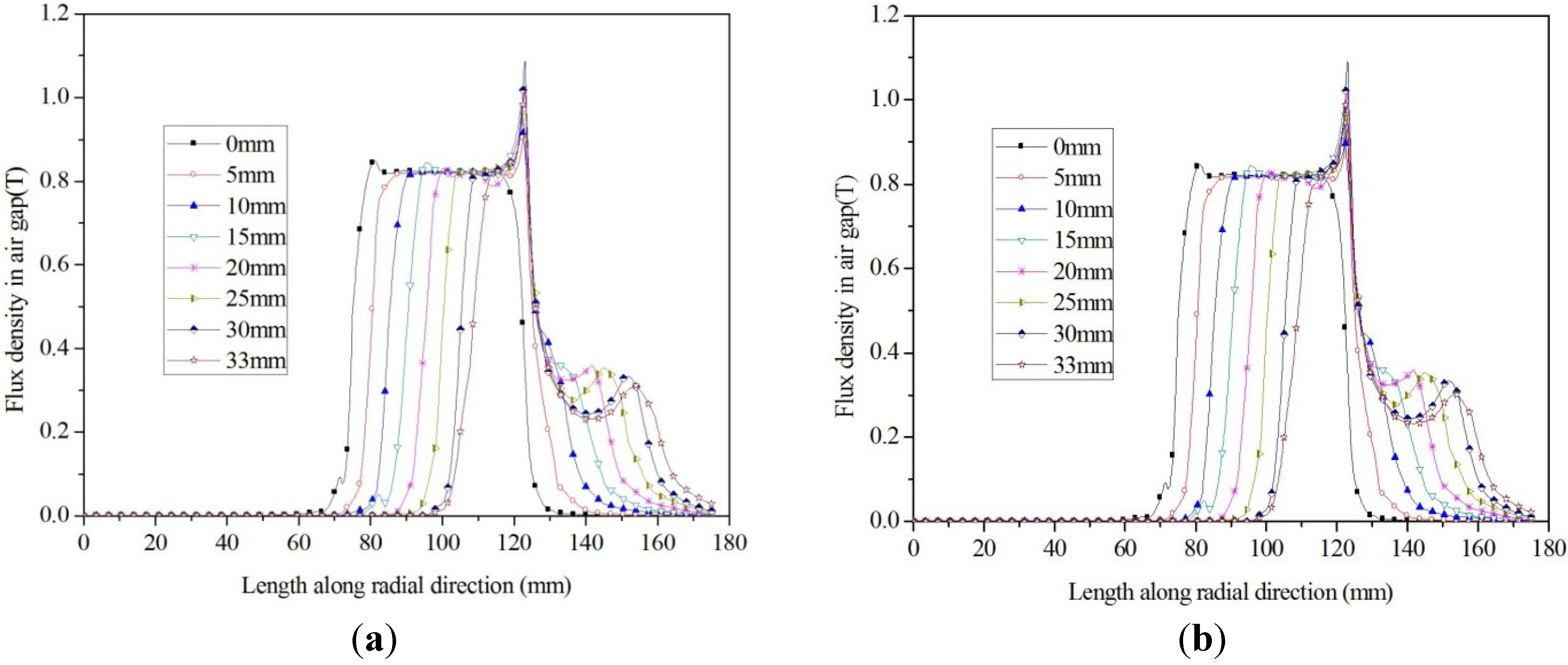
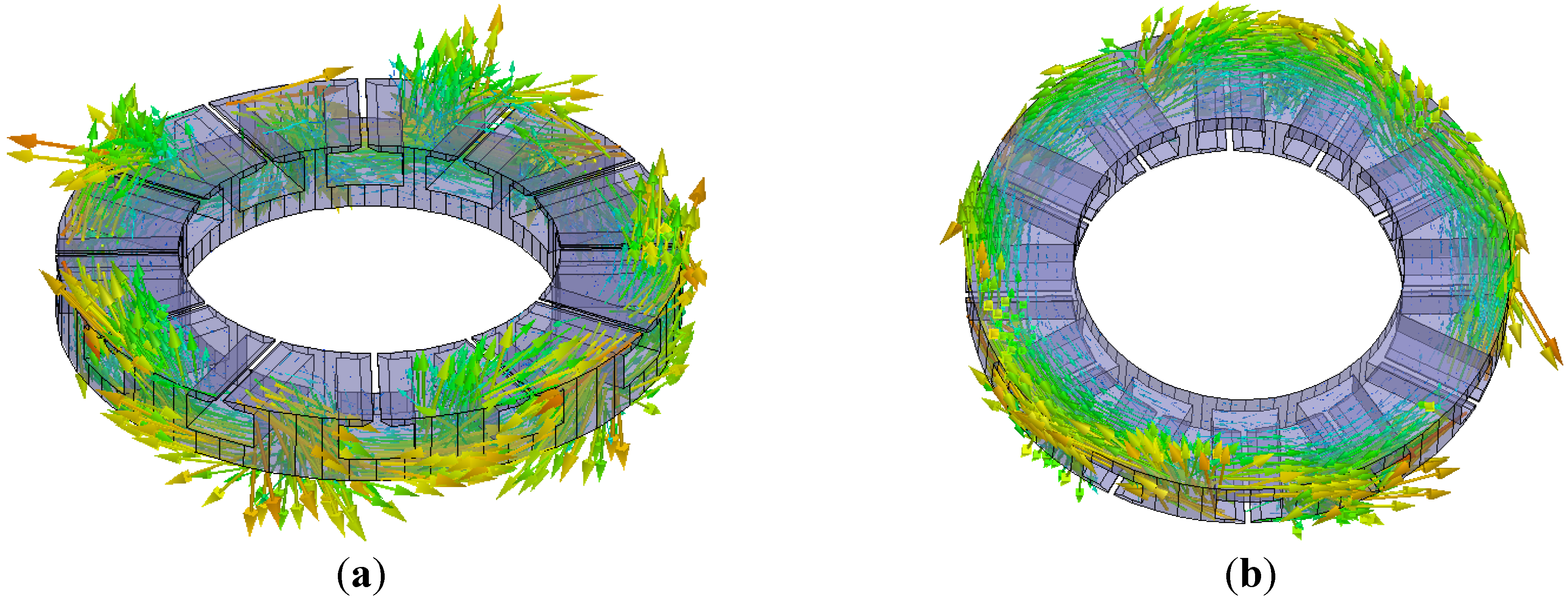
The amplitude of magnetic flux density distributed in the air gap, teeth and yoke of the two machines with rolled lamination stator and SMC stator are shown in
Figure 6,
Figure 7 and
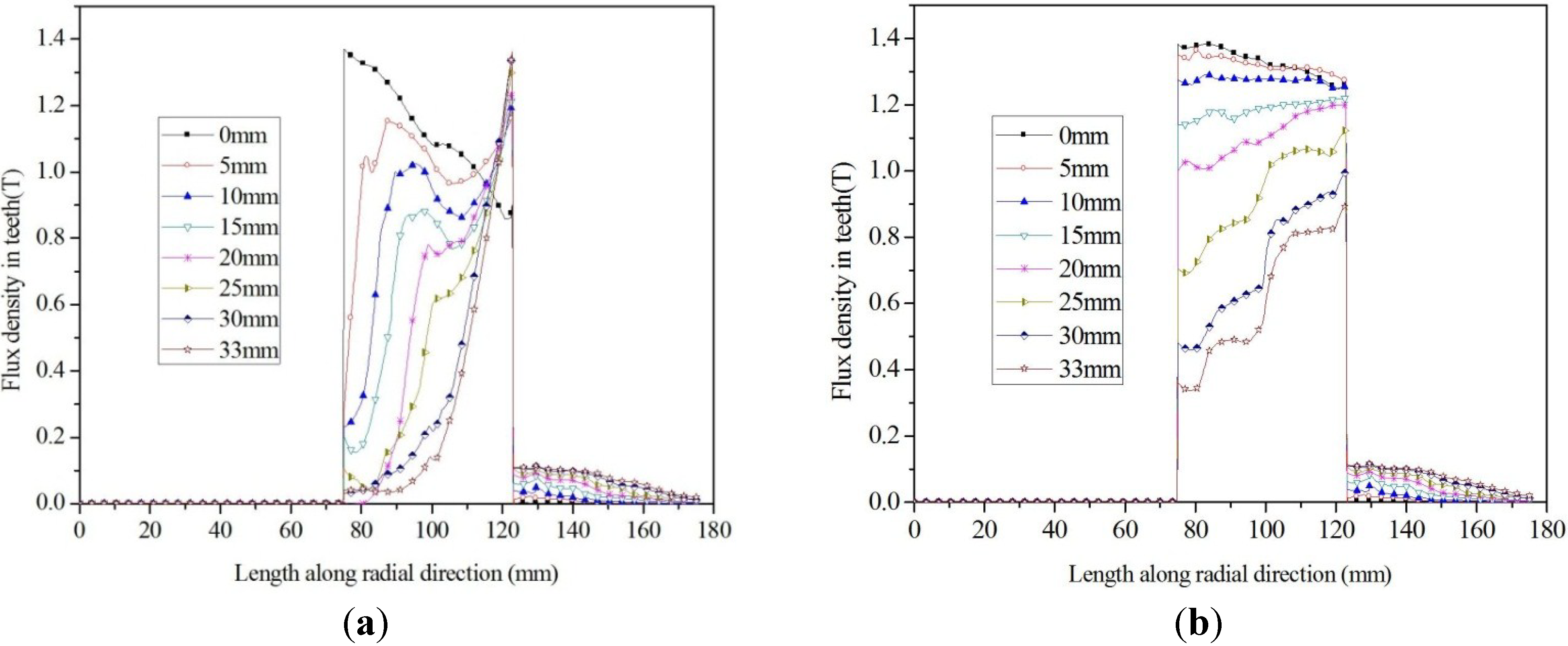
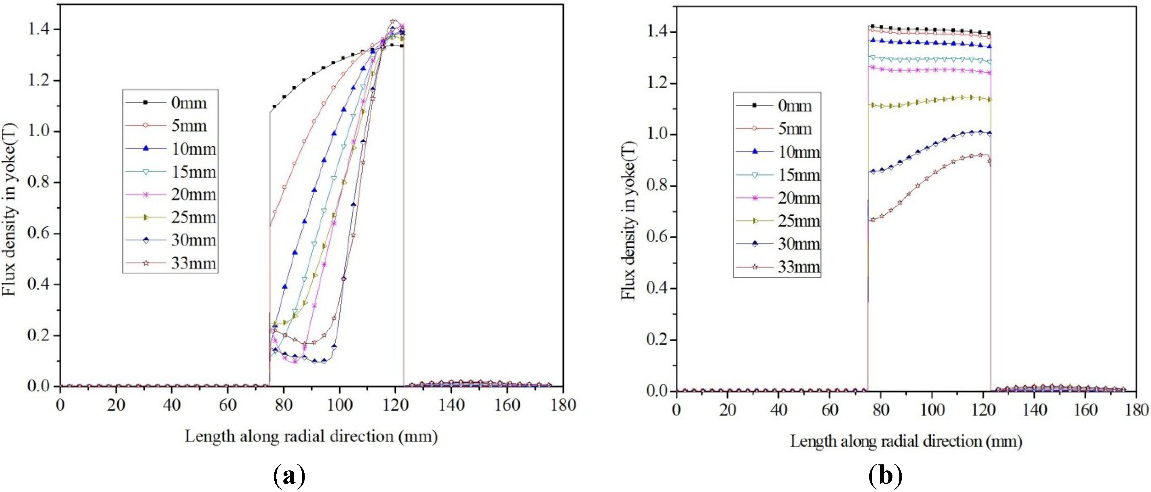
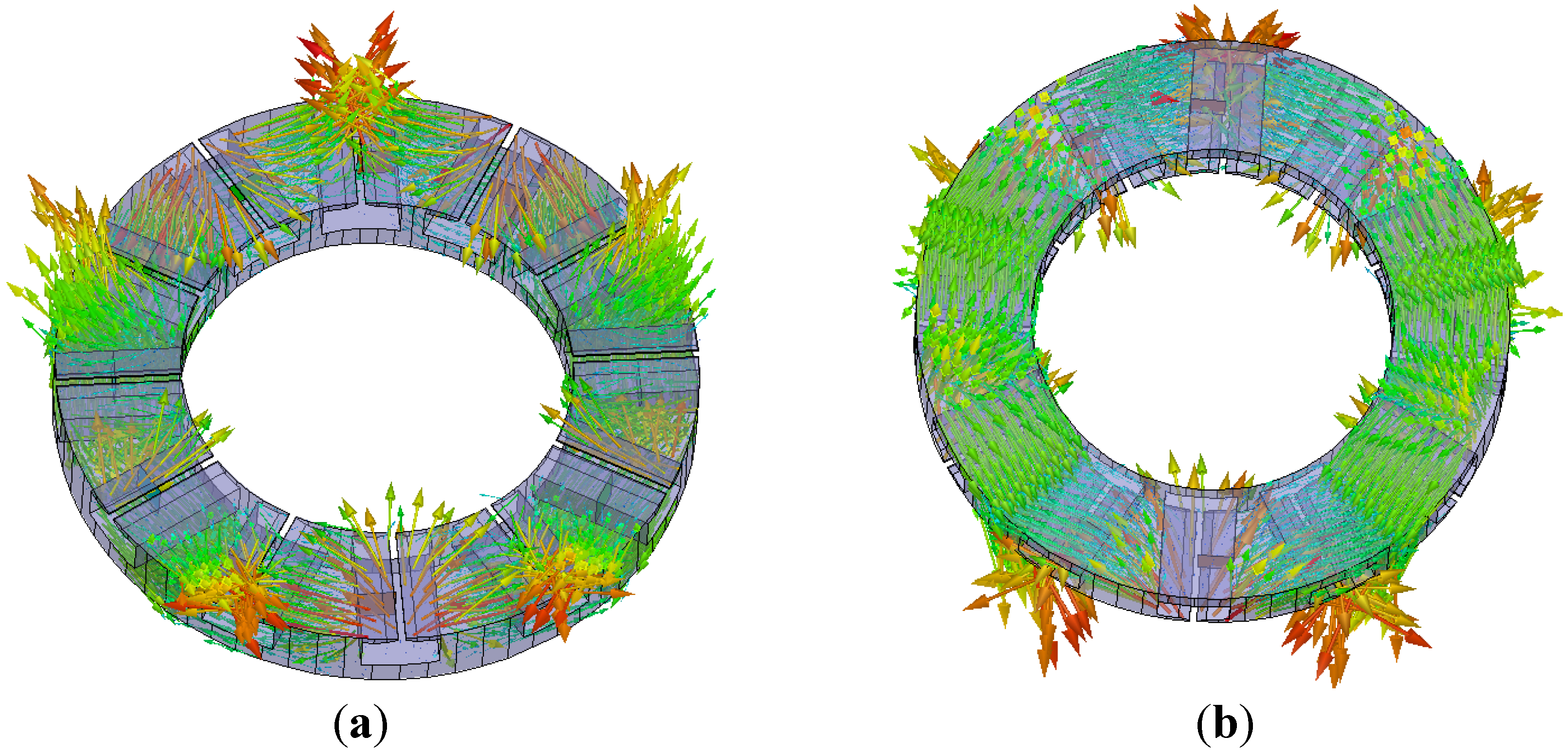
Figure 8. The magnetic density distributions in the air gaps of the two machines are almost the same. The distribution laws of flux density in teeth and yoke in machine with rolled laminated stator are the same as in the air gaps, because it is hard for the flux in laminated stator to pass the stator core along radial direction as mentioned above and shown as in
Figure 9. The flux density in Part I is almost reduced to zero without PMs. Flux density in part II changes little due to the existence of the stator iron, rotor iron and PMs as normal axial flux PMSM. The flux produced by the PMs in area III is much reduced because the equivalent reluctance in this area becomes much bigger without the stator iron. However, the distribution laws of flux density in teeth and yoke in SMC stator are much different from that in laminated stator. Although the air-gap flux density in part I is much reduced, the flux density in part I will enter stator core. Due to the 3D permeability of SMC, the flux in teeth and yoke from part II will distribute all over of the SMC stator core, including the core in part I, as shown in
Figure 10. So the magnetic flux density distribution in teeth and yoke of SMC stator are relatively even along the radial direction. However, with the PMs sliding outward, magnetic flux density distribution in teeth and yoke of SMC stator becomes small due to the reduction of part II area.
Figure 6.
The magnetic flux density distributed in the air gap: (a) rolled lamination (b) soft magnetic composite (SMC).
Figure 6.
The magnetic flux density distributed in the air gap: (a) rolled lamination (b) soft magnetic composite (SMC).
Figure 7.
The magnetic flux density distributed in the teeth: (a) rolled lamination (b) SMC.
Figure 7.
The magnetic flux density distributed in the teeth: (a) rolled lamination (b) SMC.
Figure 8.
The magnetic flux density distributed in the yoke: (a) rolled lamination (b) SMC.
Figure 8.
The magnetic flux density distributed in the yoke: (a) rolled lamination (b) SMC.
Figure 9.
3D distribution of magnetic flux density in the rolled laminated stator when PMs sliding outward: (a) view from teeth side, and (b) view from yoke side.
Figure 9.
3D distribution of magnetic flux density in the rolled laminated stator when PMs sliding outward: (a) view from teeth side, and (b) view from yoke side.
Figure 10.
3D distribution of magnetic flux density in the SMC stator when PMs sliding outward: (a) view from teeth side, and (b) view from yoke side.
Figure 10.
3D distribution of magnetic flux density in the SMC stator when PMs sliding outward: (a) view from teeth side, and (b) view from yoke side.
4.2. Influences on the Inductances
According to Equation (1), the inductances will influence the field weakening range, so it is necessary to evaluate the influence of the radial sliding PMs on the d- and q-axis inductances.
As is known, the inductance of a circuit can be calculated by
where
L is the inductance of the circuit,
i is the current in the circuit,
ψ is the flux linkage produced by
i.
For a machine, the flux linkage generated by certain current can be influenced by the magnetic circuit structure, which can be expressed as
where
I is the armature current,
is the magnetomotive force (MMF) generated by armature,
is the flux per pole generated by
, and
Λ is the permeance of the magnetic circuit.
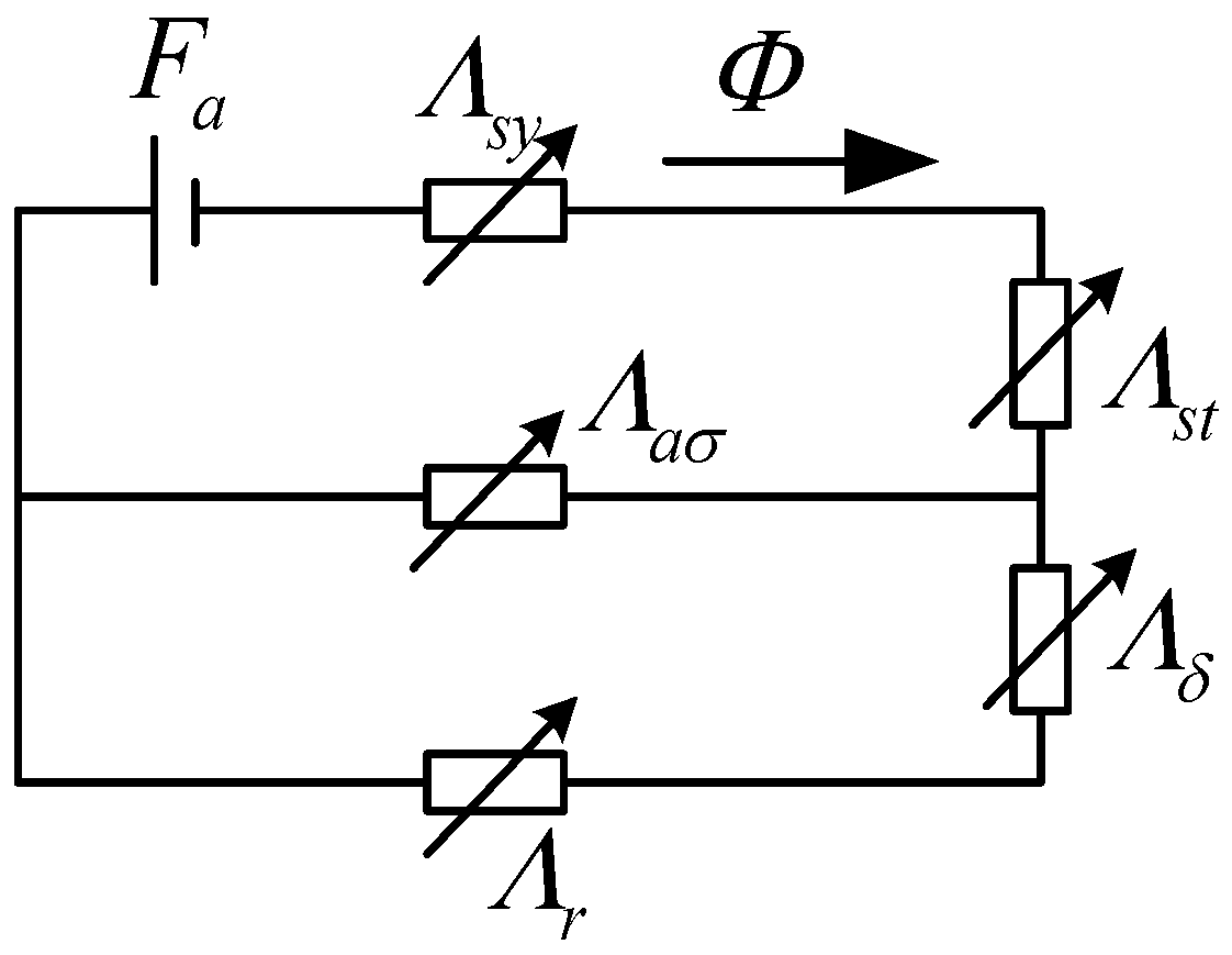
In order to analyze the magnetic circuit about the armature MMF directly, the MMF of PM is not considered here. Then the magnetic circuit of the armature MMF can be illustrated in
Figure 11. In
Figure 11 Λsy,
Λst is the yoke and teeth permeance of the stator core, respectively,
Λσ is the leakage permeance,
Λδ is the air gap permeance, and
Λr is the rotor permeance. The total equivalent permeance
Λ of the magnetic circuit can be deduced as
Figure 11.
The equivalent magnetic circuit of the armature magnetomotive force (MMF).
Figure 11.
The equivalent magnetic circuit of the armature magnetomotive force (MMF).
When the PM slide outward, the saturation of the core will decrease based on
Figure 7 and
Figure 8.
Λsy,
Λst and
Λσ will increase accordingly. Even if the
Λδ and
Λr change little, the total equivalent permeance
Λ will increase with the PM sliding out, which will result in the inductance increase. The
d- and
q-axis inductances are calculated by 3D FEM according to [
34]
where
Ld and
Lq are
d- and
q-axis inductances,
ψd and
ψq are
d- and
q-axis flux linkage,
Id and
Iq are
d- and
q-axis current.
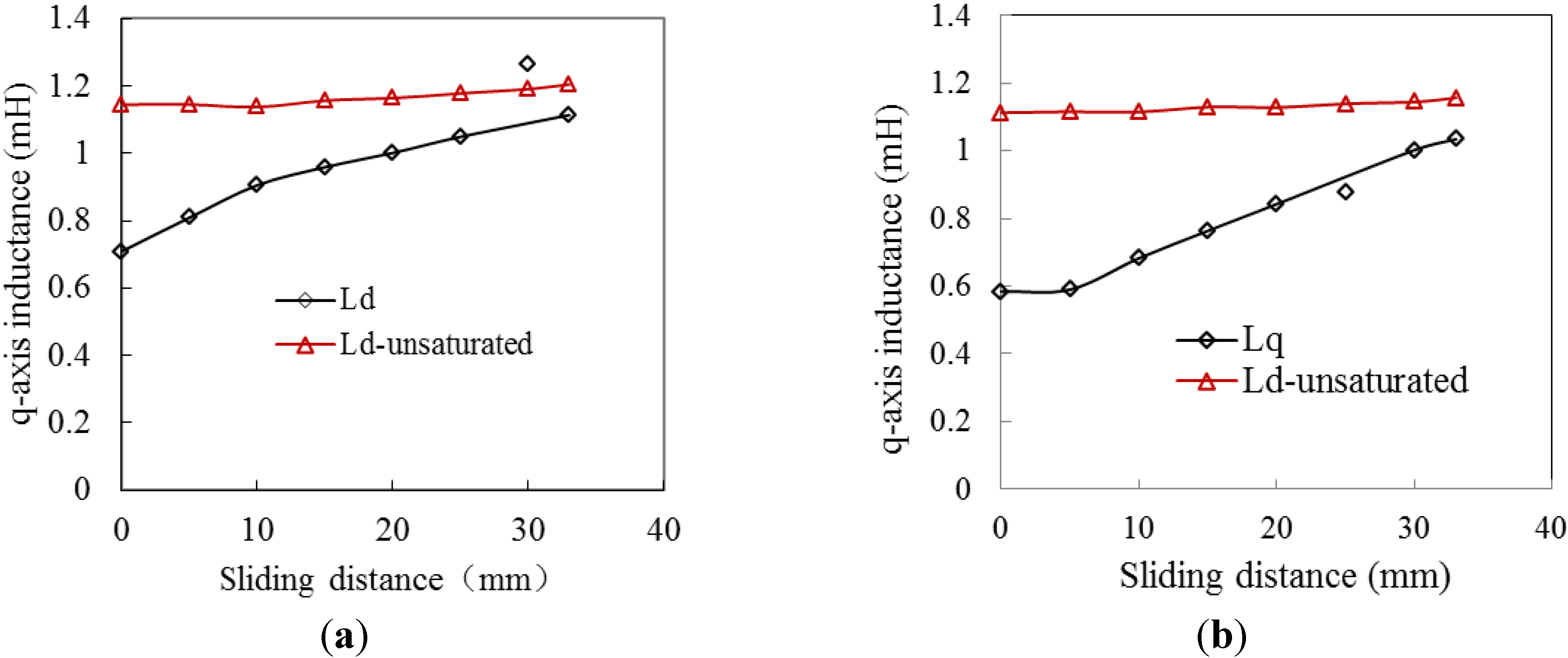
For the same current, the changing laws of
d- and
q-axis inductances
versus the sliding distance are shown in
Figure 12. The simulated inductances are in accordance with the analysis. The
d-axis and
q-axis inductances increase rapidly at first and then slowly with the PMs sliding outward, which indicates that the saturation of the iron core has much influence on the inductance. In order to validate the effect of iron core saturation on the inductance, inductances in an unsaturated case are also calculated and shown in
Figure 12. The relative permeability of iron core in unsaturated case is set to be very high μ
iron = 300000 to be close to infinite iron core permeability. It can be seen form
Figure 12, with the PMs sliding outward, the inductances in unsaturated case are almost unchanged due to a nearly constant equivalent permeance of the magnetic circuit. With the PMs sliding outward, the saturation in normal case decreasing to unsaturation, the inductances in normal case is close to inductances in unsaturated case, which validates that the saturation dose has much effect on the inductances of the machine with sliding PMs.
Figure 12.
The d- and q-axis inductances versus the sliding distance of the PMs: (a) Ld and (b) Lq.
Figure 12.
The d- and q-axis inductances versus the sliding distance of the PMs: (a) Ld and (b) Lq.
4.3. Influences on the Flux Linkage
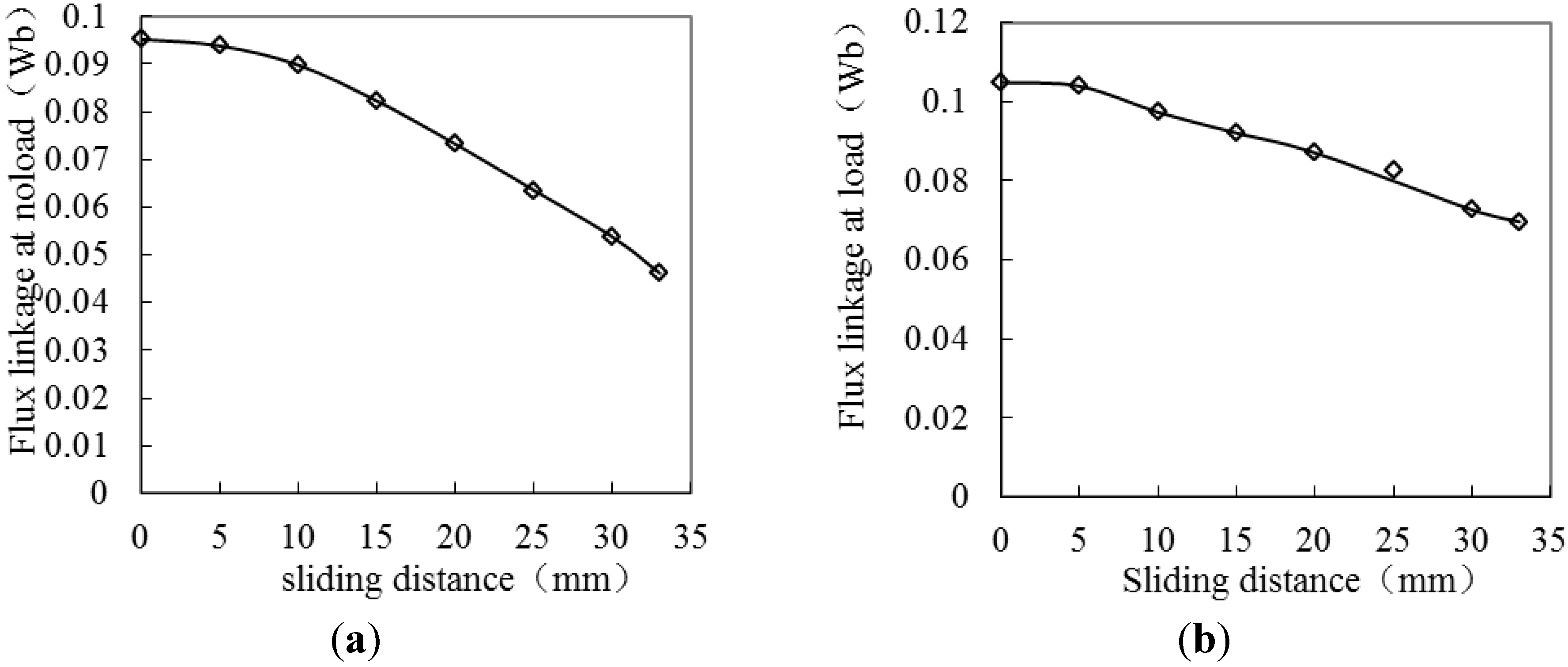
When the principle of this machine is analyzed, it mentions that the flux linkage produced by PMs is reduced with the PMs sliding outward. In this section, the flux linkage at no load ψno-load produced by PMs independently and the flux linkage at load ψload produced by PMs and armature current together will be calculated quantitatively by 3D FEM.
Considering only adopting the mechanical method of field weakening by sliding PMs, the armature current is fixed and only has
q-axis component when calculating
ψload. The changing laws of
ψno-load and
ψload with the PMs sliding distance are shown in
Figure 13. It can be seen that the decreased ratio of
ψno-load and
ψload are different. When the PMs slide outward to 33 mm, the
ψno-load is decreased to 48.5%, while the
ψload is decreased to 66.4%. The field weakening effect at load is poorer than that at load, because the
Lq increases during the PMs sliding process.
Figure 13.
Changing law of flux linkage with the PMs sliding distance: (a) ψno-load at no load (b) ψload at load.
Figure 13.
Changing law of flux linkage with the PMs sliding distance: (a) ψno-load at no load (b) ψload at load.
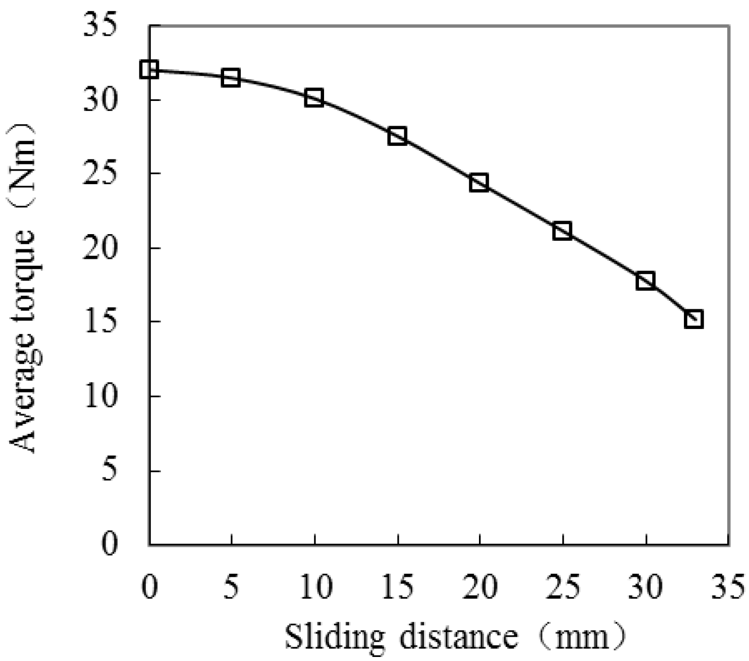
4.4. Influences on the Torque
Because the PMs sliding has much influence on the distribution of the magnetic field, consequently, the electromagnetic torque must also be influenced. So the influence of the PMs sliding on torque is researched in this part. The electromagnetic torque
Tem can be expressed as
where
p is the number of pole pairs.
Under a certain
iq without
id, the electromagnetic torque
Tem of the machine is proportional to the
ψf and
Tem will decrease with the PMs sliding outward, which will be similar as the
ψf. Using 3D FEM, the calculated average electromagnetic torque of the machine is shown in
Figure 14. The calculated results are in agreement with the analysis.
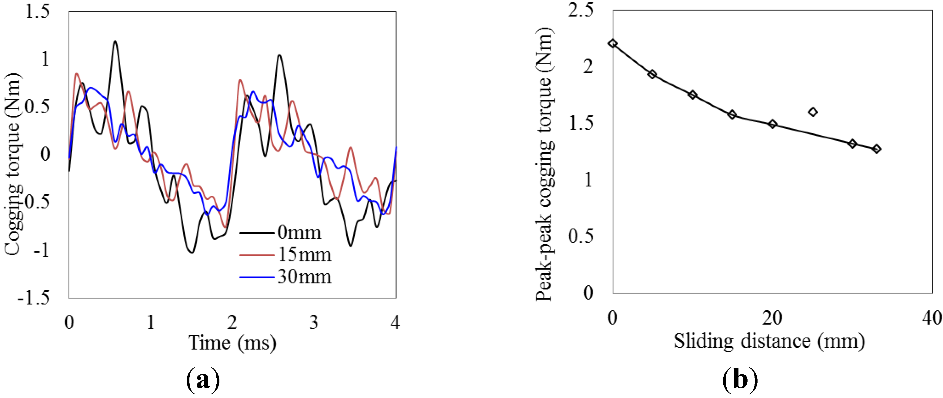
The cogging torque is also influenced by sliding PMs. The calculated cogging torque of the machine is shown in
Figure 15. In
Figure 15a, only the cogging torque at sliding distances of 0 mm, 15 mm and 30 mm are shown to see the curves more clearly.
Figure 15b shows the relationship between peak-peak value of cogging torque and the PM sliding distance. The cogging torque also decreases with the PMs sliding outward. In addition, due to the adoption of factional slot and optimization of shape of PMs when designing the machine, the cogging torque is small.
Figure 14.
Average electromagnetic torque with the PMs sliding distance.
Figure 14.
Average electromagnetic torque with the PMs sliding distance.
Figure 15.
Cogging torque with the PMs sliding distance: (a) cogging torque curve, (b) peak-peak value of cogging torque.
Figure 15.
Cogging torque with the PMs sliding distance: (a) cogging torque curve, (b) peak-peak value of cogging torque.
5. Evaluation on the Field Weakening Characteristics
The field weakening characteristics can be expressed by torque-speed curve and power-speed curve. Constant torque area is below the base speed. Field weakening area is above the base speed, which is also constant power area ideally. During the constant torque area, a constant current is applied on q axis. Above the base speed, several cases are compared with the voltage no more than ulim.
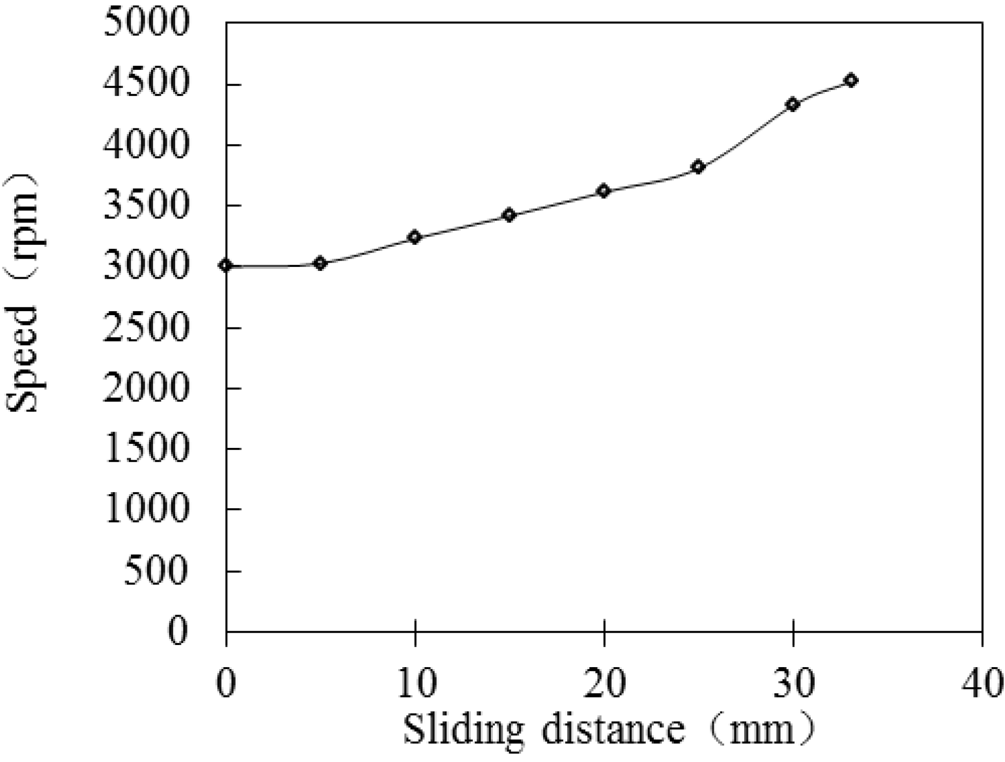
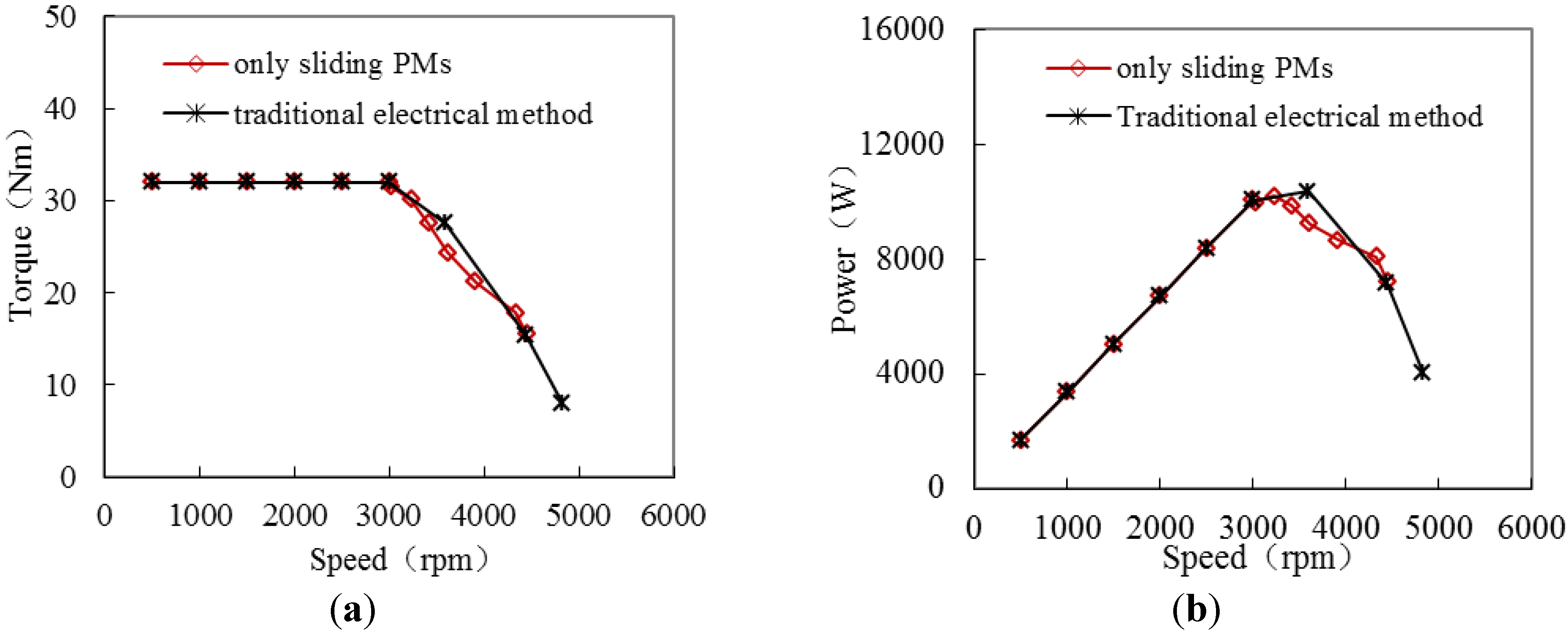
5.1. Comparison of Mechanical Method and Traditional Electrical Method
Traditional electrical method of increasing the
id and decreasing
iq without moving the PMs is researched to provide the reference of evaluating the mechanical method. The torque-speed curve using traditional electrical method can be obtained by normal method. Mechanical method of sliding PMs is researched independently with a constant current on
q axis. In this case, the relationship between the speed and the PM sliding distance can be obtained according to Equation (11) and
Figure 13b indirectly, as shown in
Figure 16. Then the torque-speed curve can be obtained based on
Figure 14 and
Figure 16. The field weakening results of the electrical and mechanical methods are shown in
Figure 17. It can be seen that the field weakening effect caused by mechanical method is almost the same as that by traditional electrical method. The speed is increased by no more than two times of the base speed using either of the two methods. The power cannot keep constant above the base speed. So the combination of the mechanical and electrical method is researched in the following part.
Figure 16.
Relationship between the speed and the PMs sliding distance.
Figure 16.
Relationship between the speed and the PMs sliding distance.
Figure 17.
Comparison of the field weakening results by mechanical and electrical methods: (a) torque-speed and (b) power-speed.
Figure 17.
Comparison of the field weakening results by mechanical and electrical methods: (a) torque-speed and (b) power-speed.
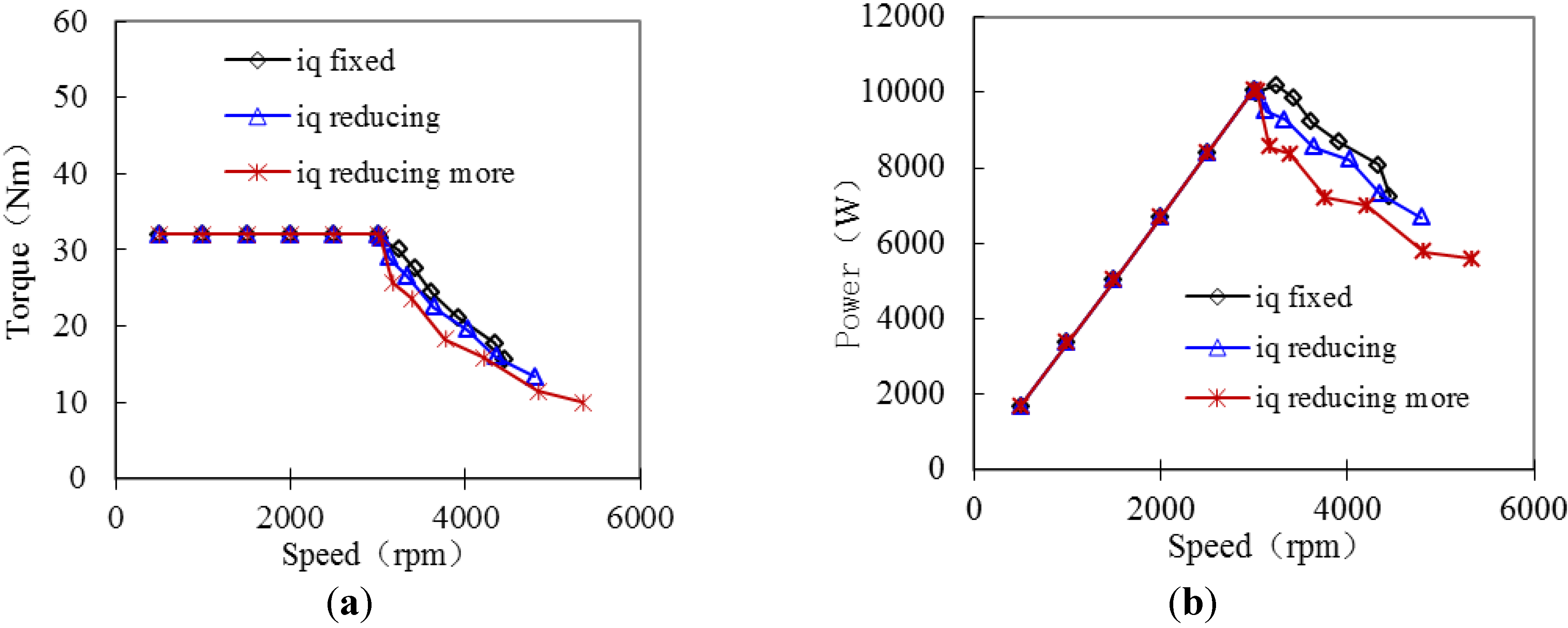
5.2. Combination of Mechanical Method and Electrical Method
As analyzed before, field-weakening effect caused by only sliding the PMs is not satisfying due to the strong armature reaction at load. For a certain machine, the
q-axis current can be reduced to decrease the flux linkage at load, thus enhancing the speed range. So the
iq is tried to be reduced without any
id during the PMs sliding outward. The corresponding torque-speed and power-speed curves are shown in
Figure 18. It can be seen that reducing
iq indeed enhances the speed range. But in this way the torque is reduced and the power is also reduced, which indicates that only reducing
iq is not a good way.
Figure 18.
Field weakening results with only iq existing: (a) torque-speed and (b) power-speed.
Figure 18.
Field weakening results with only iq existing: (a) torque-speed and (b) power-speed.
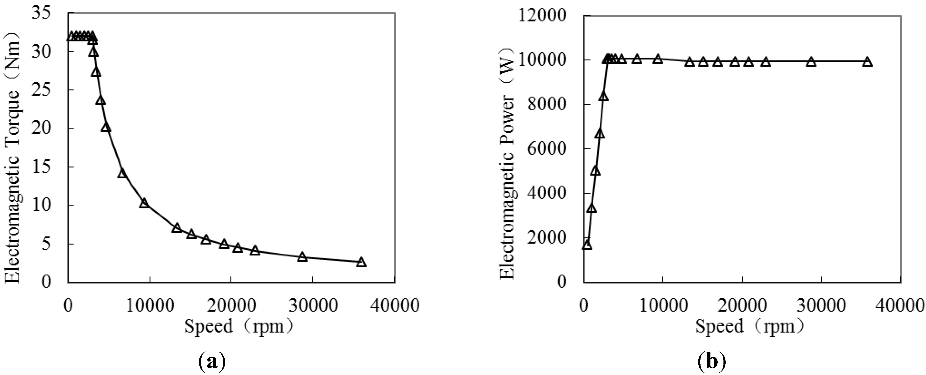
However, if the mechanical method of sliding PMs is combined with the electrical method of increasing
d-axis current and decreasing
q-axis current while keeping the total current no more than rated current, the field weakening result will be different. In this way the electromagnetic power
Pem can be calculated based on Equations (1) and (10) as
According to Equation (12), adjusting
d-axis current
id and
q-axis current
iq carefully, combined with a reduced flux linkage
ψf, it is possible to keep the power constant above the base speed. A group of armature currents matching different sliding distance are carefully chosen based on Equations (1), (10) and (12) to keep the power as constant as possible. The armature root mean square (RMS) current above base speed is shown in
Table 2. When the PMs slide to 33 mm, the PMs are prevented by the end frame and will not slide outward further with the speed increasing. Then the
id is also unchanged.
Figure 19 shows the field weakening capability with mechanical method and adjusting
id and
iq while keeping the current amplitude no more than rated current. From the
Figure 19, it can be seen that the speed range and constant power range are very wide, up to ten times of the base speed. Very satisfying field weakening capability is achieved by optimized matching the mechanical method and electrical method.
Table 2.
The armature root mean square (RMS) current above base speed.
Table 2.
The armature root mean square (RMS) current above base speed.
| Sliding distance (mm) | iq (A) | id (A) | (A) |
|---|
| 0 | 33.00 | 0.00 | 33.00 |
| 5 | 32.998 | 0.43 | 33.00 |
| 10 | 32.94 | 2.02 | 33.00 |
| 15 | 32.75 | 4.05 | 33.00 |
| 20 | 32.12 | 7.57 | 33.00 |
| 25 | 31.43 | 10.05 | 33.00 |
| 30 | 26.36 | 19.86 | 33.00 |
| 32 | 21.38 | 25.14 | 33.00 |
| 33 | 15.20 | 29.29 | 33.00 |
| 33 | 13.44 | 29.29 | 32.22 |
| 33 | 12.02 | 29.29 | 31.66 |
| 33 | 10.61 | 29.29 | 31.15 |
| 33 | 9.76 | 29.29 | 30.87 |
| 33 | 8.84 | 29.29 | 30.59 |
| 33 | 7.07 | 29.29 | 30.13 |
| 33 | 5.66 | 29.29 | 29.83 |
Figure 19.
Field weakening capability with combination of mechanical and adjusting id and iq: (a) torque-speed and (b) power-speed.
Figure 19.
Field weakening capability with combination of mechanical and adjusting id and iq: (a) torque-speed and (b) power-speed.
7. Conclusions
An axial flux PMSM with radially sliding PMs to fulfill field-weakening control by mechanical method is investigated in this paper. The field weakening principle and the structure of this kind of axial flux PMSM are introduced and analyzed. The influences of radially sliding PMs on magnetic flux density distribution are analyzed based on 3D FEM. It is found that the magnetic flux density distribution in stator iron is different from that in air gap due to the 3D equal permeability. The changing laws of d- and q-axis inductances with sliding distance are analyzed and discussed based on magnetic circuit and FEM calculation. The influences of radially sliding PMs on flux linkage and torque are also analyzed and evaluated.
The field weakening effects by the mechanical method of PMs sliding and by the electrical method of adjusting the d- and q-axis current are compared. It is found the field weakening effects by the two methods are more or less, and neither of them can provide satisfying field weakening capability independently. The combination of mechanical method and electrical method is researched. It is found that the mechanical method of PMs sliding combining only q-axis current without any d-axis current cannot provide a satisfying field weakening effect. However, field-weakening capability of the machine can be much improved by the optimized combination of the mechanical method of PMs sliding and by adjusting the d- and q-axis current together while keeping the total current no more than rated current.
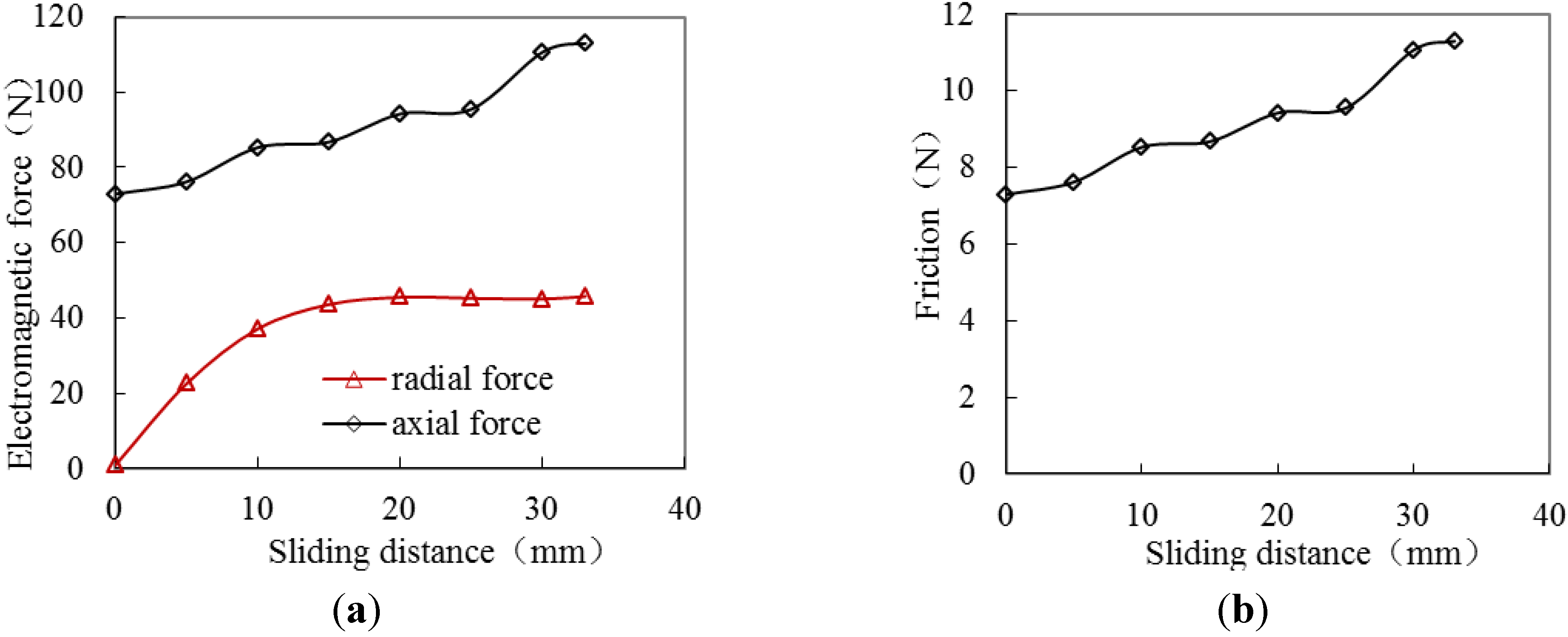
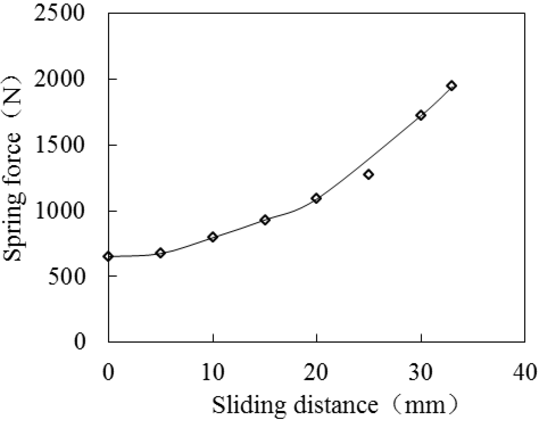
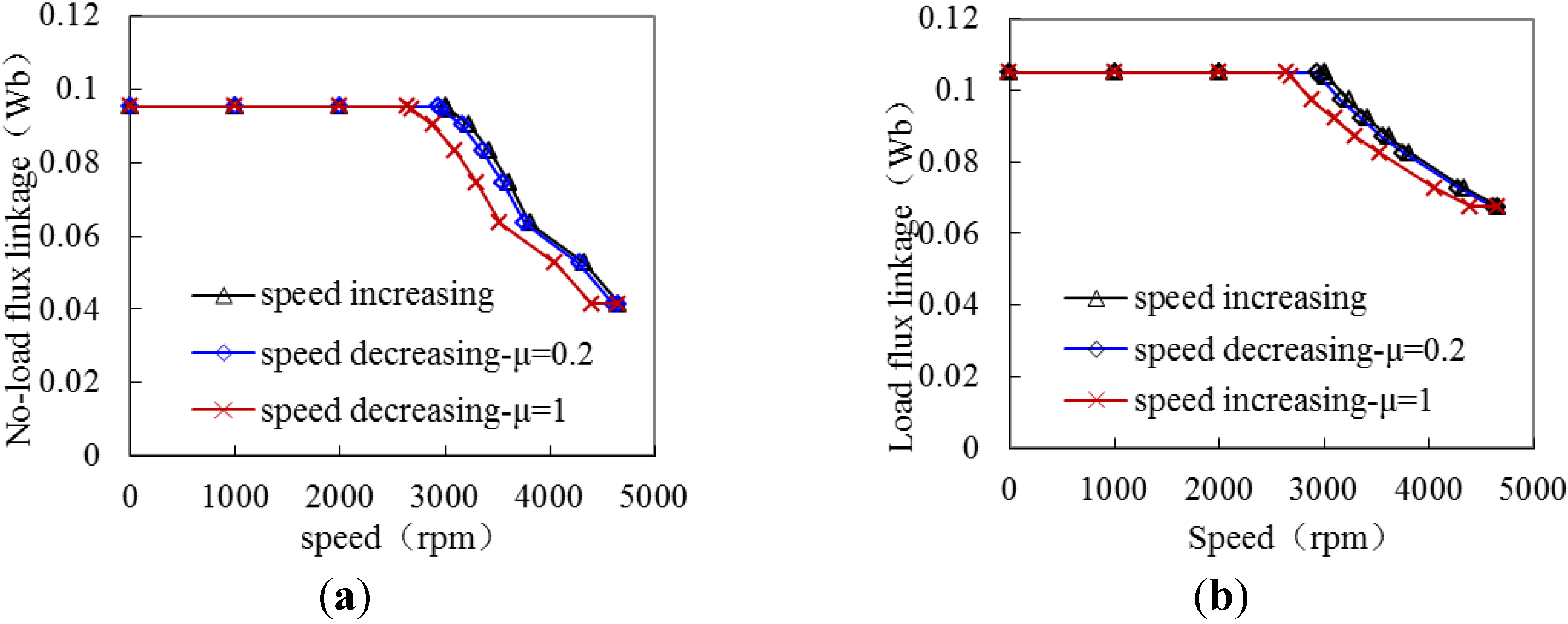
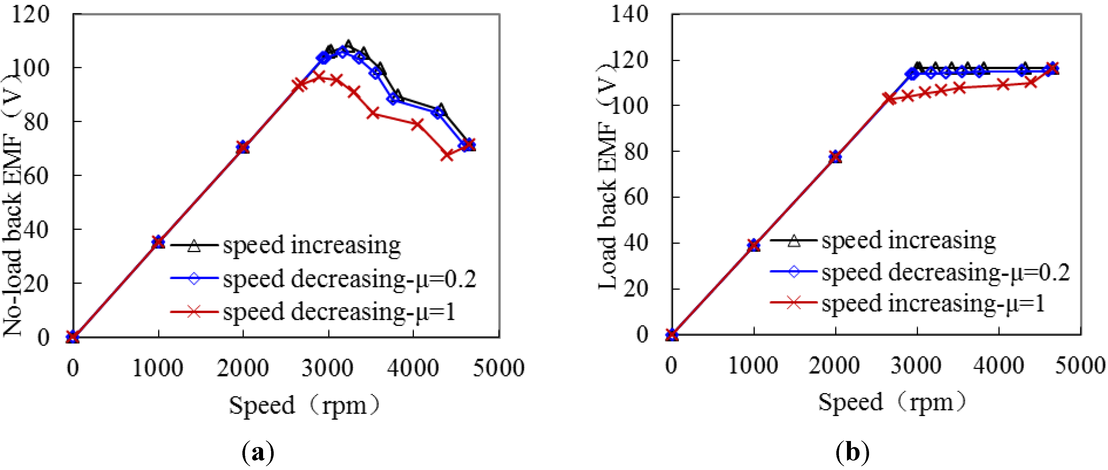
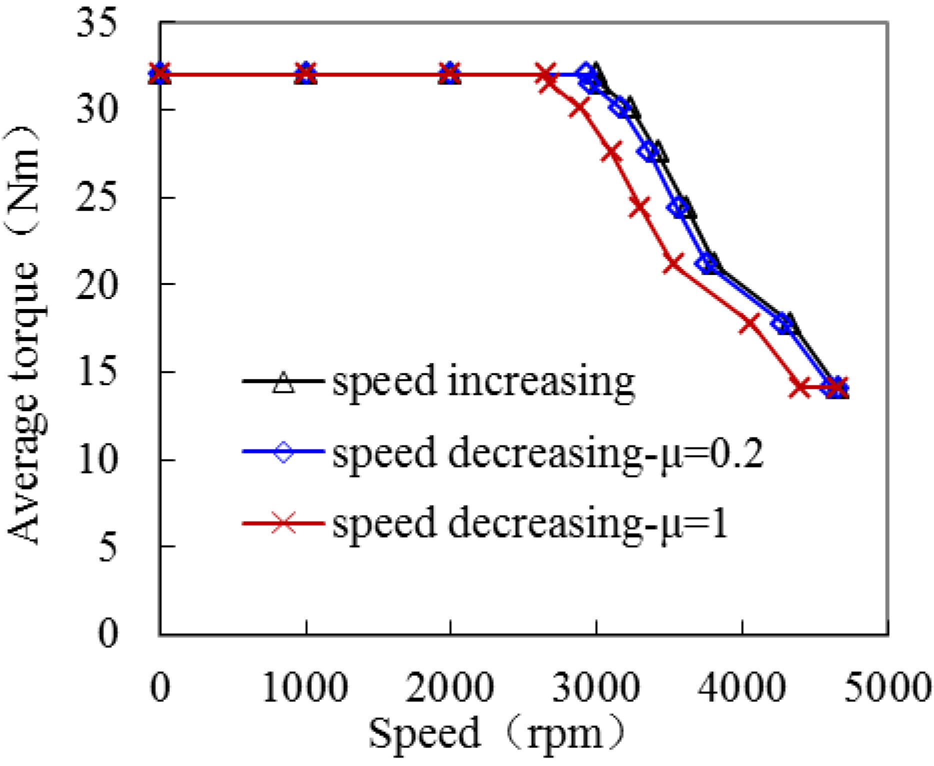
The forces on the PMs are analyzed and calculated. The radial electromagnetic force, friction and the spring force on the PM overcome the centrifugal force together to ensure the PMs at an ideal position. During speed increasing and speed decreasing above base speed, the hysteretic characteristics on flux linkage, back EMF and torque caused by the friction of the PMS are investigated, which provide useful reference for designing this kind of machine.


