
Experimental and Numerical Investigation of Termination Impedance Effects in Wireless Power Transfer via Metamaterial


Abstract
: This paper presents an investigation of the transmitted power in a wireless power transfer system that employs a metamaterial. Metamaterials are a good means to transfer power wirelessly, as they are composed of multiple inductively-coupled resonators. The system can be designed and matched simply through magneto-inductive wave theory, particularly when the receiver inductor is located at the end of the metamaterial line. However, the power distribution changes significantly in terms of transmitted power, efficiency and frequency if the receiver inductor slides along the line. In this paper, the power distribution and transfer efficiency are analysed, studying the effects of a termination impedance in the last cell of the metamaterial and improving the system performance for the resonant frequency and for any position of the receiver inductor. Furthermore, a numerical characterisation is presented in order to support experimental tests and to predict the performance of a metamaterial composed of spiral inductor cells with very good accuracy.1. Introduction
In recent years, wireless power transfer (WPT) has been one of the most interesting and innovative topics studied by both research centres and technology industries, particularly due to the large number of potential applications in which it can be applied (vehicle charging, electronic and biomedical devices [1–3]). However, even if WPT is widely developed for electronic devices and improved for simple systems, to date, there are still a lot of open issues, e.g., the low efficiency due to large distances or misalignments between emitter and receiver coils. Generally, resonators or metamaterials can be used in order to solve these problems [4], arranging, for example, the coupled resonators along a line or in two directions in a plane and letting the receiver slide on them or in a slab whose electrical parameters can be optimised in order to enhance the power transfer efficiency between two-faced coils [5,6]. In this way, power transfer for longer distances is enabled. Such a multiresonator system introduces new problems, particularly in terms of efficiency and frequency: in fact, for a large number of coupled resonators, the efficiency falls, and the power delivered to the receiver coil no longer coincides with the maximum transmitted one for every operating frequency.
In a previous paper, Stevens showed that the efficiency can be improved along a metamaterial line, as depicted in Figure 1, with the introduction of a termination impedance connected to the last cell, whose value depends on the receiver position [7]. This paper extends the considerations in [7] with an accurate investigation of the effects of the termination impedance on the transmitted power and efficiency as a function of frequency and receiver position. Moreover, efficiency peaks are discussed in this paper. Finally, a numerical characterisation is also shown in order to predict with good accuracy the performance of the system analysed.
This paper is based on magneto-inductive wave theory (MIW) to simply explain the behaviour of a metamaterial. Hence, a brief theoretical discussion of MIW is presented in Section 2. Further, the theoretical modelling of the single resonator used in experiments and the system is shown in Section 3. In Sections 4 and 5, the experimental apparatus and the main results of the transmission coefficient and efficiency are presented, and some comparisons between measures and simulated predictions are given in order to validate and support the experimental tests. Finally, the discussions of the results and conclusions are presented in Section 6.
2. Theoretical Background and Basic Assumptions
The theory behind magneto-inductive waves (MIW) has been widely discussed in the literature [8–10]. In this section, the main considerations for wireless power transfer applications and equivalent circuits are reviewed. Generally, a metamaterial is a periodic array formed by resonator cells (resonant circuits formed by an inductor L and a capacitor C in series) coupled to each other magnetically. Considering a system composed of a finite number n of cells, as shown in Figure 2, the associated equivalent circuit is analytically described by the following system of n equations:
It is known in the literature that the matching condition is achieved by introducing a terminal impedance in the last cell equal to (shown in Figure 2), becoming purely real for f = f0 and equal to ZT = ω0M, as demonstrated in [11,13].
Generally, considering a receiver inductor with a load Rload in series and facing the i-th cell of the metamaterial, it is enough to add a further equation in Equation (1) in order to represent the whole system shown in Figure 3a:
In this sense, it is enough to set:
The multiple resonator system can be simplified with an equivalent impedance , representing the whole metamaterial and connected in series to the impedance of the first cell, as depicted in Figure 4. If the matching condition is satisfied, then [14]. In all other cases, the equivalent impedance can be also calculated analytically through a continued fraction (as used in [15] for four resonators) whose value depends mainly on the position of the receiver and a possible terminal impedance. For example, considering the receiver located on the third cell of a metamaterial composed of five cells and a termination impedance , the equivalent impedance can be calculated as follows (this case corresponds to the experimental setup detailed in Section 4):
Hence, the input impedance can be calculated as at the resonant frequency.
3. Single Cell and System Characterisation
In Figure 5, an example of the resonator cell considered in this work and its equivalent lumped circuit model are shown. L and R are respectively the self-inductance and the resistance considered as a function of frequency associated with the metallic track, and Cp represents the stray capacitance of the resonator. For a single layer resonator, the self-inductance depends on the external dimension, l, the number of turns, N, the width of the conductor tracks, w, and the space between turns, s. The self-inductance L can be predicted with a procedure based on the theory of partial inductance [16]. Here, L is found by calculating the partial self- and mutual inductances between all of the sub-elements in which the whole structure is divided. For the partial self-inductance calculation, the exact formula of rectangular bars proposed in [17] is used, and the numerical procedure detailed in [18] is implemented for the partial mutual inductance calculation. Finally, for the calculation of the stray capacitance and AC resistance, the validated formulas reported in [19,20] can be used in order to take account of both skin and proximity effects increasing significantly with frequency.
For a multiple resonator system, the equivalent circuit may be more complex, because the mutual inductance between each couple of cells must be taken into account. Hence, the whole system could be easily represented in a matrix form through the following equation:
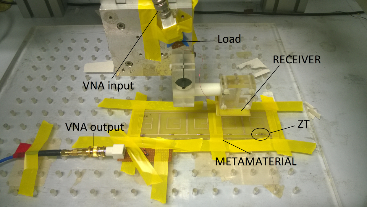
4. Experimental Setup
The metamaterial used in this work consists of five equal resonators of a square shape, mutually coupled and arranged in a planar line separated by gaps equal to g = 0.2 mm. The experimental system is shown in Figure 6.
The single metamaterial cell is fabricated with a printed circuit board (PCB) with N = 1, l = 40 mm, w = 1 mm and s = 1 mm. The value of the measured self-inductance is 0.135 μH, equal to the numerically calculated one. The mutual inductance between two cells is calculated from measurement by resonance splitting, and it is found equal to −16.3 nH (very close to the predicted one −18.7 nH). As the stray capacitance is small, a lumped capacitance equal to 1 nF is added to each cell in order to tune the resonant frequency to f0 = 13.56 MHz (as it is a license-free industrial, scientifical and medical (ISM) band). All of the capacitances are parallel to the inductors. The source is connected in series as in Figure 2. Finally, the measured and calculated AC resistances are equal to 0.303 Ω and 0.152 Ω, respectively. The measured AC resistance includes also the solder connections and series resistance of the lumped capacitances plus any radiation losses. The layout of the receiver resonator used in these tests is identical to the cells of the metamaterial: a load resistance (Rload = 3.3 Ω) is soldered in series to the lumped capacitance of 1 nF. In case the emitter and receiver coils are single-layer solenoid or single-layer spiral coils, they can be designed with the procedure presented in [22].
An HP 8753 vector network analyser (VNA) (Keysight Technologies, Santa Rosa, CA, USA) was used in order to supply the source and to measure the transmission coefficient S21: the instrument output is connected to the first cell, and the received signal is measured across the load resistance. This type of circuital connection involves an adjustment of the transmitted power measured as the internal impedance of the VNA is equal to Z0 = 50 Ω, quite different from Rload. Hence, the measured value is smaller than the real one; consequently, it is possible to adjust the measure and to find the effective efficiency across the load through:
The transmission coefficient and efficiency are studied for three different conditions, corresponding to different termination impedance values. In particular:
Condition A: ZT = 0 Ω (corresponding to a short-circuited last cell);
Condition B: ZT = 120 Ω (much larger than ω0M);
Condition C: ZT ≫ 120 Ω (corresponding to an open circuit last cell).
Finally, the measurements are made considering the receiver inductor sweeping along the whole length of the metamaterial at a height of almost 9 mm, corresponding to the receiver distance at which the matching condition Equation (5) is satisfied.
5. Simulation and Measurement Results
The measured values of the transmission coefficient, S21, in dB for each termination impedance considered as a function of frequency and receiver position are shown in Figure 7. As can be noticed, the plot of S21 regarding Condition A is quite different from those relevant to the other two conditions, which are very similar. The maximum values of the transmission coefficient are distributed for different frequencies and positions depending on the considered condition. Particularly, in the frequency range between about 12.4 and 15.5 MHz and when the receiver is positioned at 180 mm, i.e., perfectly facing the last resonator, S21 is over −10 dB for Condition A, but much smaller for Conditions B and C (−20 dB). Moreover, for Condition A, the concentration of high transmission coefficient values around the resonant frequency means that the matching condition is achieved. For Conditions B and C, high transmission coefficient values occur for different positions of the receiver along the metamaterial, as is confirmed by the measures of S21 and the adjusted efficiency presented in Figure 8.
In fact, as can be seen, the behaviour of the efficiency alternates highs and lows, and the peaks are located every two cells. If the last cell is short-circuited (ZT = 0 Ω), the maximum of the efficiency is achieved when the receiver faces the I, III and V resonator (cell centres at 20, 100 and 180 mm). The introduction of a high impedance (ZT = 120 Ω or ZT ≫ 120 Ω) involves a displacement of peaks by one cell: in fact, the efficiency peaks occur when the receiver is on the II and IV cell (cell centres at 60 and 140 mm). Furthermore, observing the equivalent impedance values reported in Table 1, the value of Zeq is very close to ω0M = 1.39 Ω in positions where the efficiency is maximum. Finally, the correspondence of the peaks at the resonant frequency is further validated by showing the behaviour of S21 as a function of frequency when the receiver is perfectly located on each cell, as depicted in Figure 9. The behaviour of the transmission coefficient is strongly affected by the introduction of a termination impedance ZT, which changes the distribution of the transmission coefficient peaks in the resonant frequency bandwidth. In particular, with the connection or disconnection of the termination impedance, the maximum values of S21 can be obtained at the resonant frequency in all of the receiver positions.
The measurements are then compared with numerical simulations, made implementing the formulas in Section 3 in a MATLAB programme [23]. In particular, the efficiency, peaks of efficiency and optimum frequencies are studied, taking into account only two different conditions, A (ZT = 0 Ω, shown in Figure 10a,c) and B (ZT = 120 Ω, shown in Figure 10b,d), as Conditions B and C (ZT ≫ 120 Ω) are found to be equivalent. Peaks of efficiency are defined as the maximum values of efficiency occurring at the resonant frequency and optimum frequencies as those frequencies at which the peaks of efficiency are achieved. As shown, all of the simulations match with very good agreement the experimental data. Considering the efficiency, the largest difference is obtained for the receiver centre between 0 and 60 mm in Condition B (as can be noticed in Figure 10b). Moreover, a small difference (10%) is obtained for the receiver centre between 80 mm and 120 mm, regarding the peaks of efficiency. Consequently, the prediction of the optimum frequencies shows a little disagreement with the measurement for the same receiver positions (as shown in Figure 10d), even if the general behaviour is similar to the measurement.
Finally, it is worth noticing that the efficiency and efficiency peaks are very close when the receiver is perfectly aligned with Resonators I, III and V for Condition A (see Figure 10a) or to Resonators II and IV for Condition B (see Figure 10b). Correspondingly, in the same positions, the optimum frequencies of both Conditions A and B are close to the resonant frequency, as shown in Figure 10b,d, respectively. This behaviour enhances the assumption that the matching condition occurs every two cells (as previously demonstrated by the equivalent impedance values; Table 1).
6. Discussion and Conclusions
The experimental analysis presented in this work shows the behaviour of the power delivered to a receiver sliding along a metamaterial for three different values of a termination impedance, ZT (Conditions A, B and C presented in Section 4). In the experiments, it was found that the termination impedance affects the received power behaviour modifying the equivalent impedance Zeq and, hence, the position of the receiver where the maximum value of efficiency is achieved. In this way, it is possible to obtain the best behaviour for any position of the receiver by varying the ZT value between zero and a high value (in this work, 120 Ω, almost a hundred-times larger than ω0M) in order to maintain the equivalent impedance at always about ω0M (as reported in Table 1). In Figure 11, the envelopes of the efficiency and peaks of efficiency obtained for the termination impedances of 0 and 120 Ω with the respective optimum frequencies are shown as a function of the receiver position. It can be seen that the envelope of the efficiency has globally higher values than the cases with constant termination impedances. Moreover, the envelope of the efficiency overlaps the envelope of the efficiency peaks for a number of receiver positions. Furthermore, the optimum frequencies, with the exception of the first cells, are closer to the resonant frequency: this is due to the equivalent impedance closer to the matching condition.
Transmitted power and efficiency are investigated under different termination impedance conditions, which improve significantly the efficiency at the resonant frequency. All of the considerations presented in this work are supported by circuital, numerical and experimental results.
Author Contributions
G. Puccetti performed the simulations and wrote the paper. C. J. Stevens gave input to the theoretical work, organized the experimental setup and measurements. U. Reggiani and L. Sandrolini contributed to the writing and organization of the paper with particular reference to the presentation and discussion of the simulation and measurement results.
Conflicts of Interest
The authors declare no conflict of interest.
References
- Villa, J.L.; Sallán, J.; Llombart, A.; Sanz, J.F. Design of a high frequency Inductively coupled power transfer system for electric vehicle battery charge. Appl. Energy. 2009, 86, 355–363. [Google Scholar]
- Jang, Y.; Jovanovic, M. A contactless electrical energy transmission system for portable-telephone battery chargers. IEEE Trans. Ind. Electron. 2003, 50, 520–527. [Google Scholar]
- RamRakhyani, A.; Mirabbasi, S.; Chiao, M. Design and optimization of resonance-based efficient wireless power delivery systems for biomedical implants. IEEE Trans. Biomed. Circuits Syst. 2011, 5, 48–63. [Google Scholar]
- Wang, B.; Yerazunis, W.; Teo, K.H. Wireless power transfer: Metamaterials and array of coupled resonators. Proc. IEEE. 2013, 101, 1359–1368. [Google Scholar]
- Urzhumov, Y.; Smith, D.R. Metamaterial-enhanced coupling between magnetic dipoles for efficient wireless power transfer. Phys. Rev. B 2011, 83. [Google Scholar] [CrossRef]
- Kim, H.; Seo, C. Highly efficient wireless power transfer using metamaterial slab with zero refractive property. Electron. Lett. 2014, 50, 1158–1160. [Google Scholar]
- Stevens, C. Magnetoinductive waves and wireless power transfer. IEEE Trans. Power Electron. 2014, PP, 1. [Google Scholar]
- Shamonina, E.; Kalinin, V.; Ringhofer, K.; Solymar, L. Magneto-inductive waveguide. Electron. Lett. 2002, 38, 371–373. [Google Scholar]
- Chan, C.; Stevens, C. Two-dimensional magneto-inductive wave data structures, Proceedings of 5th European Conference on Antennas and Propagation (EUCAP), Rome, Italy, 11–15 April 2011; pp. 1071–1075.
- Shamonina, E.; Kalinin, V.A.; Ringhofer, K.H.; Solymar, L. Magnetoinductive waves in one, two, and three dimensions. J. Appl. Phys. 2002, 92, 6252–6261. [Google Scholar]
- Solymar, L.; Shamonina, E. Waves in Metamaterials; Oxford University Press (OUP): Oxford, UK, 2009. [Google Scholar]
- Stevens, C.; Chan, C.; Stamatis, K.; Edwards, D. Magnetic Metamaterials as 1-D Data Transfer Channels: An Application for Magneto-Inductive Waves. IEEE Trans. Microw. Theory Tech. 2010, 58, 1248–1256. [Google Scholar]
- Syms, R.R.A.; Young, I.R.; Solymar, L. Low-loss magneto-inductive waveguides. J. Phys. D Appl. Phys. 2006, 39, 3945. [Google Scholar] [CrossRef]
- Stevens, C. Power transfer via metamaterials. Comput. Mater. Contin. 2013, 33, 1–18. [Google Scholar]
- Zhang, Y.; Zhao, Z.; Chen, K. Frequency-splitting analysis of four-coil resonant wireless power transfer. IEEE Trans. Ind. Appl. 2014, 50, 2436–2445. [Google Scholar]
- Ruehli, A.E. Inductance calculations in a complex integrated circuit environment. IBM J. Res. Dev. 1972, 16, 470–481. [Google Scholar]
- Hoer, C.; Love, C. Exact inductance equations for rectangular conductors with applications to more complicated geometries. J. Res. Nat. Bur. Stand. Sec. C Eng. Inst. 1965, 69C, 127–137. [Google Scholar]
- Sonntag, C.; Lomonova, E.; Duarte, J. Implementation of the Neumann formula for calculating the mutual inductance between planar PCB inductors, Proceedings of 18th International Conference on Electrical Machines, Vilamoura, Portugal, 6–9 September 2008; pp. 1–6.
- Bilotti, F.; Toscano, A.; Vegni, L. Design of Spiral and Multiple Split-Ring Resonators for the Realization of Miniaturized Metamaterial Samples. IEEE Trans. Antennas Propag. 2007, 55, 2258–2267. [Google Scholar]
- Jow, U.M.; Ghovanloo, M. Design and optimization of printed spiral coils for efficient transcutaneous inductive power transmission. IEEE Trans. Biomed. Circuits Syst. 2007, 1, 193–202. [Google Scholar]
- Puccetti, G.; Reggiani, U.; Sandrolini, L. Experimental analysis of wireless power transmission with spiral resonators. Energies. 2013, 6, 5887–5896. [Google Scholar]
- Sandrolini, L.; Reggiani, U.; Puccetti, G.; Neau, Y. Equivalent circuit characterization of resonant magnetic coupling for wireless transmission of electrical energy. Int. J. Circuit Theory Appl. 2013, 41, 753–771. [Google Scholar]
- MATLAB, Version 8.0.0 (R2012b); The MathWorks Inc: Natick, MA, USA, 2012.


| Receiver position | ZT = 0 Ω | ZT = 120 Ω ZT ≫ 120 Ω | ||
|---|---|---|---|---|
| Zeq [Ω] | η% | Zeq [Ω] | η% | |
| I cell | 1.6 | 67% | 7.2 | 30% |
| II cell | 0.2 | 10% | 1.1 | 58% |
| III cell | 1.4 | 53% | 6.2 | 5% |
| IV cell | 0.3 | 5% | 1.2 | 49% |
| V cell | 1.3 | 43% | 5.8 | 0% |
© 2015 by the authors; licensee MDPI, Basel, Switzerland This article is an open access article distributed under the terms and conditions of the Creative Commons Attribution license (http://creativecommons.org/licenses/by/4.0/).
Share and Cite
Puccetti, G.; Stevens, C.J.; Reggiani, U.; Sandrolini, L. Experimental and Numerical Investigation of Termination Impedance Effects in Wireless Power Transfer via Metamaterial. Energies 2015, 8, 1882-1895. https://doi.org/10.3390/en8031882
Puccetti G, Stevens CJ, Reggiani U, Sandrolini L. Experimental and Numerical Investigation of Termination Impedance Effects in Wireless Power Transfer via Metamaterial. Energies. 2015; 8(3):1882-1895. https://doi.org/10.3390/en8031882
Chicago/Turabian StylePuccetti, Giovanni, Christopher J. Stevens, Ugo Reggiani, and Leonardo Sandrolini. 2015. "Experimental and Numerical Investigation of Termination Impedance Effects in Wireless Power Transfer via Metamaterial" Energies 8, no. 3: 1882-1895. https://doi.org/10.3390/en8031882