Article

New TA Index-Based Rollover Prevention System for Electric Vehicles

1
National Engineering Laboratory for Automotive Electronic Control Technology, School of Mechanical Engineering, Shanghai Jiao Tong University, Shanghai 200240, China
2
University of Michigan—Shanghai Jiao Tong University Joint Institute, Shanghai Jiao Tong University, Shanghai 200240, China
*
Author to whom correspondence should be addressed.
Energies 2015, 8(3), 2008-2031; https://doi.org/10.3390/en8032008
Submission received: 20 November 2014 / Revised: 12 February 2015 / Accepted: 13 February 2015 / Published: 13 March 2015

Abstract

:
In addition to clean transportation and energy savings, electric vehicles can inherently offer better performance in the field of active safety and dynamic stability control, thanks to the superior fast and accurate control characteristics of electric motors. With the novel wheel status parameter TA for electric vehicles proposed by the authors in an earlier publication, a new TA index (TAI)-based rollover prevention method is presented in this paper to improve the driving performance of EVs equipped with in-wheel motors. A three-level electric vehicle control structure is used to analyze the effective control steps for rollover prevention with the newly proposed TAI method. The simulation is conducted using an in-house developed electric vehicle dynamic model. The simulation results prove the feasibility of using TAI to detect rollover. The experiment uses an electric vehicle equipped with four in-wheel motors in the authors’ research lab. The vehicle parameter and performance data are imported to CarSim, which is industrial standard vehicle dynamic analysis software to run the rollover test. The experimental results also demonstrate that TAI is an effective method of rollover prevention.

1. Introduction

Electric vehicles (EVs) have been widely considered and adopted by industry and the market as a green transportation technology with fewer emissions. Researchers have proved that EVs can be more efficient at saving energy and have lower total energy consumption than conventional internal combustion engine vehicles (ICEVs) [1,2,3,4,5]. Taking the results from [1] as an example, EVs can have 35.6% energy saving and 17.1% CO2 emissions reduction, compared to ICEVs. Especially, for EVs using in-wheel motors, since there is no mechanical transmission, differential, and redundant drive shafts, the energy efficiency can be further improved [2]. Moreover, with in-wheel motors, the total torque demand can be distributed to each wheel independently. Intelligent methods for optimal torque distribution are capable of more than 20% energy consumption savings [3,4]. In addition, flexible regenerative braking algorithms with in-wheel motors could further enhance the energy efficiency of EVs [5]. In this regard, consistently improving the performance of EVs equipped with in-wheel motors by applying novel control methods is still very critical and necessary for saving energy and providing clean transportation.
Besides their clean emission and efficient energy consumption merits, it has also been commonly recognized that with the superior control performance of electric motors, EVs are inherently more suitable in the field of active safety and dynamic stability control, compared to ICEVs [6]. First, the torque response of motors is extremely fast, typically in milliseconds; and the torque feedback of motors can be easily measured and accurately controlled [7,8,9,10]. Second, for EVs, it is easy to implement distributed in-wheel motor systems [11,12,13]. In-wheel motors can generate additional yaw moment to EVs by applying different driving or braking forces between the right and left side wheels, which is very helpful for the dynamic stability control of vehicles [14,15,16,17,18]. Third, with motor torque and wheel acceleration obtained, longitudinal slip and road conditions can be easily detected [10,19,20], which can enhance the control performance of the anti-lock braking system (ABS) and traction control system (TCS). Furthermore, the lateral active safety control could also be benefit from the slip status and road conditions obtained from the motor torque based dynamics.
Rollovers are high-risk events for high speed vehicles. Rollovers happen due to either tripping due to external inputs (e.g., stones on the road), or a high lateral acceleration when turning sharply [21]. According to National Highway Traffic Safety Administration (NHTSA), although only 3% vehicle accidents are caused by rollovers, the passenger car fatalities caused by rollovers can reach up to 33% [22,23]. Rollovers are even more dangerous for popular sport utility vehicles (SUVs) since their centers of gravity are generally higher than those of passenger sedans. Rollover prevention is still a critical problem in safety control, especially for newly developed EVs.
There are two steps in rollover prevention. The first step is the detection of the potential rollover, and then is the implementation of anti-rollover control. Several methods are proposed for rollover prevention. The most popular one is the differential braking system, which reduces the speed or yaw rate of vehicles to prevent rollover [23]. Other methods include the drive torque management rollover prevention method [24], the steer-by-wire method [25], the active suspension method, and so on.
For the rollover prevention methods mentioned above, it is necessary and important to detect rollovers accurately. There are basically two types of rollover detection methods. The first type is to calculate the roll angle from the vehicle model [23]. In this method, the roll angle, roll rate, and lateral acceleration are necessary for rollover detection. However, during the vehicle rollover process, the vehicle model before the wheel lift-off is not the same as that after the wheel lift-off. Moreover, the vehicle parameters or road conditions are not constant for a running vehicle. These are the impediments for the model-based rollover detection methods. The second type is the rollover index method. For the real time rollover detection, a rollover index comprising the vertical tire loads between the left and right sides of the vehicles is proposed [21,22,26]. This index-based method works easily when the vehicle or road conditions vary, however the vertical tire loads of both sides in this rollover index method are not easy to measure. Although force sensors can be installed on the wheels, this new design can be expensive. In [27], Bevly proposed a rollover detection method using GPS to measure the three-dimensional speeds of the vehicle, integrated with an INS sensor to continuously estimate the vehicle sideslip and tire cornering stiffness based on the Kalman filter. Unfortunately this method also requires additional sensors which will increase the cost of the system.
Due to the coupling effects between the motion in the longitudinal and lateral directions, the vehicle dynamics are not independent in these two directions. The major coupling effects include three aspects: tire force coupling, weight shift coupling, and kinetic coupling [13]. The status of a driving wheel can provide information about the equivalent inertia of the quarter vehicle [28]. Using the quarter vehicle equivalent inertia, the dynamics of an EV with in-wheel motors can be well controlled with the new method proposed in this paper. In [11], a novel parameter-based anti-skid control method for EVs was proposed with consideration of the the real world resistance. In this motor torque to wheel acceleration (TA) method, TA is proved to be an active wheel status indicator instead of the slip ratio.
In order to control the EV dynamics, researchers have proposed different control structures. A relatively simple one is two-level control, including one upper level and one lower level in the control structure [14,22,29]. The upper level control determines the desired torque and yaw command, while the lower level control allocates the reference driving or braking forces to the wheels. However, the minor control loop at each driving wheel can be faster than the chassis control loop even in the lower level [6], so these two control loops should be separated. In addition, as discussed in the literature [22], the effect of allocating desired torque to driving wheels and adjusting the reference yaw moment are different in rollover prevention. Thus, for EV roll dynamic analysis, a three-level control structure is more suitable [30].
Given this discussion above, a cost-efficient and effective rollover prevention method with appropriate control structures is still necessary, especially for EVs whose advantages in active safety and dynamic stability control should be fully considered and exploited. In this paper, a new index, called TA index (TAI) for short, is first proposed based on four wheel TA parameters for the rollover prevention of EVs. TA is the ratio of motor torque to wheel acceleration, which is a wheel status indicator and will be comprehensively described in Section 2.2. With the new TAI method, the rollover can be detected without any additional sensors, which is very suitable for implementation in low-cost real-time applications. The three-level EV control structure is used with the TAI anti-rollover control method to achieve the effective control steps for rollover prevention. To demonstrate the applicability of the proposed approach, an in-house EV dynamic model developed by the authors’ research group is used for the simulation. In the experiments, an electric vehicle equipped with four in-wheel motors is used, with its parameter and performance data imported to CarSim, which is the industrial standard vehicle dynamic analysis software used in this paper to run the rollover test. The experimental results also prove that TAI is an effective rollover prevention method.
This paper is organized as follows: the background including the EV dynamic model and the wheel status indicator TA is introduced in Section 2. The newly proposed TAI rollover detection method and the three-level anti-rollover control structure are provided in Section 3. The simulation results with the in-house EV dynamic model are shown in Section 4. The experimental results using the test EV as well as the industrial standard vehicle dynamic software CarSim are presented in Section 5. Conclusions and possible further work are summarized in Section 6.

2. Background

2.1. Dynamic Model of Electric Vehicles
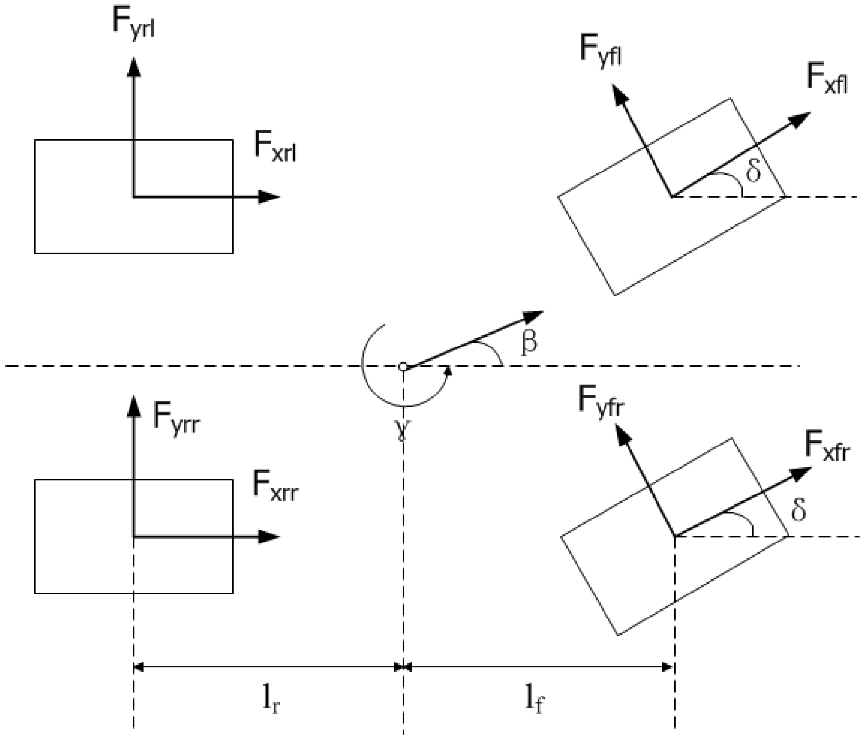
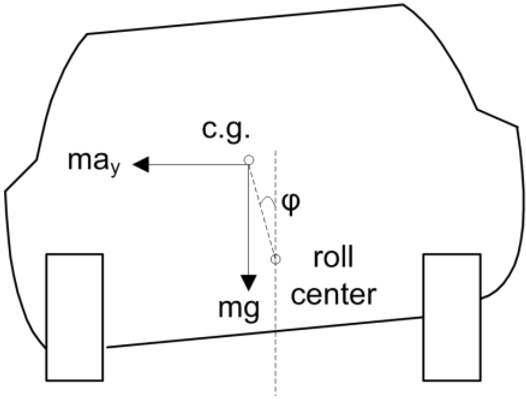
Since the left-right difference of the vehicle is ignored in the bicycle model (i.e., a one track vehicle dynamic model) [12,14,31,32], it is not suitable for the rollover analysis. Furthermore, the bicycle model is a linear model. When the friction coefficient of the road changes, or if the vehicle enters a corner at a high speed or acceleration, the dynamics of the vehicle becomes nonlinear. In that occasion, the linear bicycle model is not satisfactory any more. Thus, a nonlinear four-wheel vehicle dynamic model (i.e., two-track vehicle model, as shown in Figure 1) is necessary for the analysis. The four-wheel vehicle dynamic model considers the impact of four wheels on the vehicle’s longitudinal, lateral, and roll dynamics, which is suitable for the nonlinear dynamics of the vehicle, and thus can be used in the rollover analysis as shown in Figure 2. The major assumptions in the bicycle model are no longer required here. The four-wheel vehicle dynamic model can be described as follows:
m a x = ( F x f r + F x f l ) cosδ ( F y f r + F y f l ) cosδ + F x r r + F x r l
m a y = ( F x f r + F x f l ) sinδ + ( F y f r + F y f l ) cosδ + F y r r + F y r l
J z γ ˙ = l f ( F x f r + F x f l ) sinδ + l f ( F y f r + F y f l ) cosδ l r ( F y r r + F y r l ) + M Z
( J x x + m h s 2 ) ϕ ¨ = m a y h s cosϕ + m g h s sinϕ K ϕ C ϕ ˙
where Jxx is the inertia moment around the axis passing through the center of the gravity, parallel to the x-axis; K is the roll stiffness; and C is the damping coefficient of the rolling motion. Fxfr, Fxfl, Fyfr, Fyfl are the longitudinal force of front right wheel, longitudinal force of front left wheel, lateral force of front right wheel, lateral force of front left wheel, respectively. Fxrr, Fxrl, Fyrr, Fyrl are the longitudinal force of rear right wheel, longitudinal force of rear left wheel, lateral force of rear right wheel, lateral force of rear left wheel, respectively. δ is the steering angle of the front wheel, and Φ is the roll angle. ax and ay are the vehicle body longitudinal and lateral accelerations.
Figure 1. Four-wheel model of vehicle dynamics.
Energies 08 02008 g001
Figure 2. Roll dynamics analysis.
Energies 08 02008 g002
Furthermore, suppose the slip angle of the tire is small, so that the lateral tire force is in its linear region as shown in Figure 3; thus there are:
F y f = C f α f
F y r = C r α r
where Fyf is the lateral tire force of the front wheel, and Fyr is the lateral tire force of the rear wheel.
Figure 3. The lateral tire force and the slip angle.
Energies 08 02008 g003
According to the kinemics relations of the vehicle, we have:
α f = β + γ l f V δ
α r = β γ l r V
Substituting Equations (5)–(8) into Equations (1)–(4) leads to the state equation of the four-wheel vehicle dynamic model which can be given as:
x ˙ = A x + B u
where:
A = [ 2 C f 2 C r m V 2 l f C f + 2 l r C r J z 2 l f C f + 2 l r C r m V 2 1 2 l f 2 C f 2 l r 2 C r J z V ]
B = [ 2 C f m V 2 l f C f J z 0 1 J z ]
x = [ β γ ]
u = [ δ M z ]
In addition, according to Equation (4), the following relationship can be found at the steady state:
m a y h s cosϕ + m g h s sinϕ K ϕ = 0
Since the total lateral force Fy can be written as:
F y = F y f r + F y r l + F y r r + F y r l = m a y
We have:
m g h tanϕ K ϕ cosϕ = F y
Equation (16) indicates that at the steady state, if the total lateral force Fy is a constant, the roll angle will remain the same. This will be demonstrated in the experiment described in Section 5.2.

2.2. Wheel Status Indicator: TA

Their superior control performance is one of the most important advantages of EVs, which can offer unique active safety and dynamic stability control features. For example, the torque response of motors is very fast with the torque feedback of motors being measured easily and controlled accurately. Furthermore, it is easy to implement distributed in-wheel motor systems for EVs which can generate additional yaw moment by applying different driving or braking forces between the left and right side wheels. As mentioned previously, a control method based on motor torque to wheel acceleration for EVs has been proposed [11]. The real-world parameters have been considered in the vehicle longitudinal dynamic model, including the rolling resistance, air resistance, acceleration resistance and driving force, as shown in Figure 4.
Figure 4. Vehicle forces and wheel dynamics.
Energies 08 02008 g004
In this model, the rolling resistance is given by:
F R = m g e r
or:
F R = m g ( f R 0 + f R 1 v + f R 4 v 4 )
where e is the distance between the application of tire vertical force and the vertical center of the tire, and fR0, fR1, fR4 are friction coefficients [33].
The air resistance can be calculated as:
F L = c x A ρ 2 v 2
where cx is the drag coefficient, A is the cross-sectional area, and ρ is the density of the air.
The acceleration resistance consists of two parts, the vehicle linear acceleration FB1 and the wheel rotational acceleration FB2, which are presented as:
F B 1 = m v ˙
F B 2 = J ω ˙ r
F B = F B 1 + F B 2 = m v ˙ + J ω ˙ r
The driving force is given by:
F D = T r
Since the equilibrium function can be written as:
F R + F L + F B = F D
We have:
T r = m g e r + c x A ρ 2 v 2 + m v ˙ + J ω ˙ r
Multiplying Equation (24) by r ω ˙ , we have:
T ω ˙ = m g e ω ˙ + c x A ρ 2 ω ˙ v 2 r + m r v ˙ ω ˙ + J
The index TA is defined as:
T A = T ω ˙
With the real world resistances under consideration, TA is proved to be an active wheel status indicator, with more details provided in reference [11]. It should be noted that if the wheel acceleration equals zero, the TA can go to infinitely large. For a general wheel status detection method in the literature [11], when wheel slip occurs, the TA will decrease to a very small value. Therefore, usually the minimum TA value will be constrained, not the maximum TA. The possible large TA value will not damage the vehicle stability, nor the wheel slip status. For the TAI rollover prevention discussed in this paper, however, the maximum TA value is indeed constrained within a bound for the calculation, so the possible infinite large values of TA will not happen and thus will not damage the control performance.
As discussed in [28], for an EV with in-wheel motors, the wheel status can provide the information of the so-called “effective inertia”. When the vehicle drives on a road with low friction coefficients, or turns at a corner, the “effective inertia” shows the changes of the virtual mass. In the following discussion, a simplified wheel dynamic model shown in Figure 5 is used, with a more complex form that can be found in [11].
Figure 5. The simplified wheel dynamic model.
Energies 08 02008 g005
In Figure 5, we have:
T T r = J ω ˙
where Tr is the equivalent resistance torque.
Thus:
T ω ˙ T r ω ˙ = J
T ω ˙ J r = J
T ω ˙ = J + J r
With the above equations:
T A = J e q u i
From Equation (31), it can be found that TA implies the equivalent inertia of the wheel or the part vehicle.

2.3. Three-Level Electric Vehicle Dynamic Control Structure

A three-level EV dynamic control structure has been introduced in the literature [30], including an upper level, a middle level, and a lower level control structures, as shown in Figure 6. The upper level control determines the desired vehicle dynamics according to the driver’s inputs. Also, the safety region of the vehicle is evaluated based on the vehicle speed and the steering angle at this level. In order to track the desire vehicle dynamics, the middle level control assigns the required driving or braking torque to the four wheels. In the lower level, the torque command is applied to the in-wheel motors and the wheel slip is detected and restricted. The regenerative braking strategy is implemented in the lower level too. With this three-level control structure, the vehicle’s behavior is classified in the controller, which can benefit the active safety control functions, like TCS, ABS, and electronic stability control (ESC, here including yaw stability control, vehicle slip angle control, and rollover prevention, etc.) for EVs.
Figure 6. Three-level dynamic control structure of EV.
Energies 08 02008 g006
The proposed TAI rollover prevention method is tested in Section 5.2 and Section 5.3 with the control process implemented in the middle level and the upper level controller, respectively. From the experimental results, it can be found that applying the TAI method only in the middle level control cannot prevent the potential rollover. The effective control performance is fulfilled with the TAI method implemented in the upper level control. Here, the TAI is calculated and constrained in the desired dynamics calculation module in Figure 6, which requires the command from the driver and vehicle status as the basic information. The TA value of the wheels and the TAI calculation are both included in the vehicle status. Furthermore, the yaw moment is also recalculated in the desired dynamics calculation module and sent to the middle level for the implementation, where the desired yaw moment is allocated to the wheels. With this procedure, the total lateral force on the wheels is constrained, and the roll angle can be therefore limited as shown in Section 5.3.

3. TAI Rollover Prevention Method

3.1. TAI Rollover Detection

In this paper, a new index based on four-wheel TA parameters is proposed for the rollover detection of EVs, which is called TA index (TAI) for short. The motor torque and wheel acceleration both can be easily obtained for an EV. Thus, with the new TAI method, the rollover can be detected without any additional sensor, which is suitable for the implementation of low-cost real-time applications.
TAI is defined as:
TAI = ( TA fr + TA rr ) ( TA fl + TA rl ) ( TA fr + TA rr ) + ( TA fl + TA rl )
where TAfr, TArr, TAfl, and TArl are the TA of the front right, rear right, front left and rear left wheels, respectively. Equation (32) shows that the range of TAI is [–1,1]. If TAI reaches its minimum value, −1, it means that the total right TA, TAfr + TArr, is zero. Thus, the equivalent inertia of the two right wheels becomes zero (as discussed in Section 2.2, TA can be taken as the indicator of the equivalent inertia of the wheels) the right wheels tend to lift off, which leads to the rollover to the left side. If TAI reaches its maximum value, 1, it means that the total left TA, TAfl + TArl, is zero. Again, it shows that the equivalent inertia of the two left wheels becomes zero and the left wheels tend to lift off. In that case, the vehicle rolls to the right side. In addition, when no rollover occurs and the vehicle travels straight, TAfr + TArr should be equal to TAfr + TArr and TAI remains at zero. Therefore, in order to prevent rollover, TAI should be controlled far from approaching to ±1. In the tests, the TAI limit is set to be 0.4 to get a best control performance.

3.2. Three-Level Electric Vehicle Anti-Rollover Controller

The three-level EV anti-rollover control structure is used in this paper to analyze the effective control steps for rollover prevention with the newly proposed TAI method. In this structure, the minor control loop at each driving wheel in the lower level controller is very fast, usually compatible with the motor control frequency, which can be faster than 1000 Hz for industry level controllers. Also, the TA parameter is calculated in the lower level so that the wheel status is detected. Based on the obtained four wheel TA parameters, TAI is calculated in the middle level controller. The control actions are implemented in both middle level and upper level controllers. The detailed comparison of their effects in the experiments can be found in Section 5. With this three-level EV anti-rollover control structure, the vehicle’s behavior can be well classified; thus the conclusion can be clearly verified by the experimental results.

4. In-House EV Dynamic Model and Simulation Results

In order to demonstrate the applicability of the TAI method, we first conduct the simulation using our newly developed in-house EV dynamic model with TAI, on the Matlab/Simulink platform. The description on the in-house EV dynamic model is given first, followed by the corresponding simulation results.

4.1. In-House EV Dynamic Model

In this paper, an in-house EV dynamic model is built on the Matlab/Simulink platform, as shown in Figure 7. This in-house EV dynamic model contains the following parts: wheel dynamics including tire-road friction estimation, wheel to vehicle force and speed transmission, vehicle dynamics, and vehicle to wheel dynamics transmission.
Figure 7. In-house EV dynamic model.
Energies 08 02008 g007
In the wheel dynamics section, Pacejka’s magic formula is used to establish the relationship between the longitudinal and lateral wheel dynamics [34]. The detailed information of this formula can be found in [35]. The forces are imported into the vehicle body from the four wheels. The equations in the four-wheel vehicle dynamic model described in Section 2.2 are used for the calculation of the in-house EV dynamic model. Thus, the vehicle movement data as well as the wheel motion status can be obtained.

4.2. Simulation Results

Using the in-house four-wheel EV dynamic model, the simulation results are obtained to show the applicability of the TAI method. The vehicle parameters from the test EV in the authors’ research group are used in the simulation (more details of this test EV will be provided in Section 5 later and part of them are listed in Table 1).
Table 1. Vehicle parameters of the simulation.
ParametersValue
Vehicle mass (M)400 kg
Quarter vehicle mass (m)100 kg
Wheel equivalent radius (r)276 mm
Distance between the vehicle center of gravity and the front axle (lf)1.0 m
Distance between the vehicle center of gravity and the front axle (lr)1.3 m
Track width (lw)1.5 m
Vehicle yaw inertial (Jz)251 kgm2
Height of the vehicle center of gravity (h)0.4 m
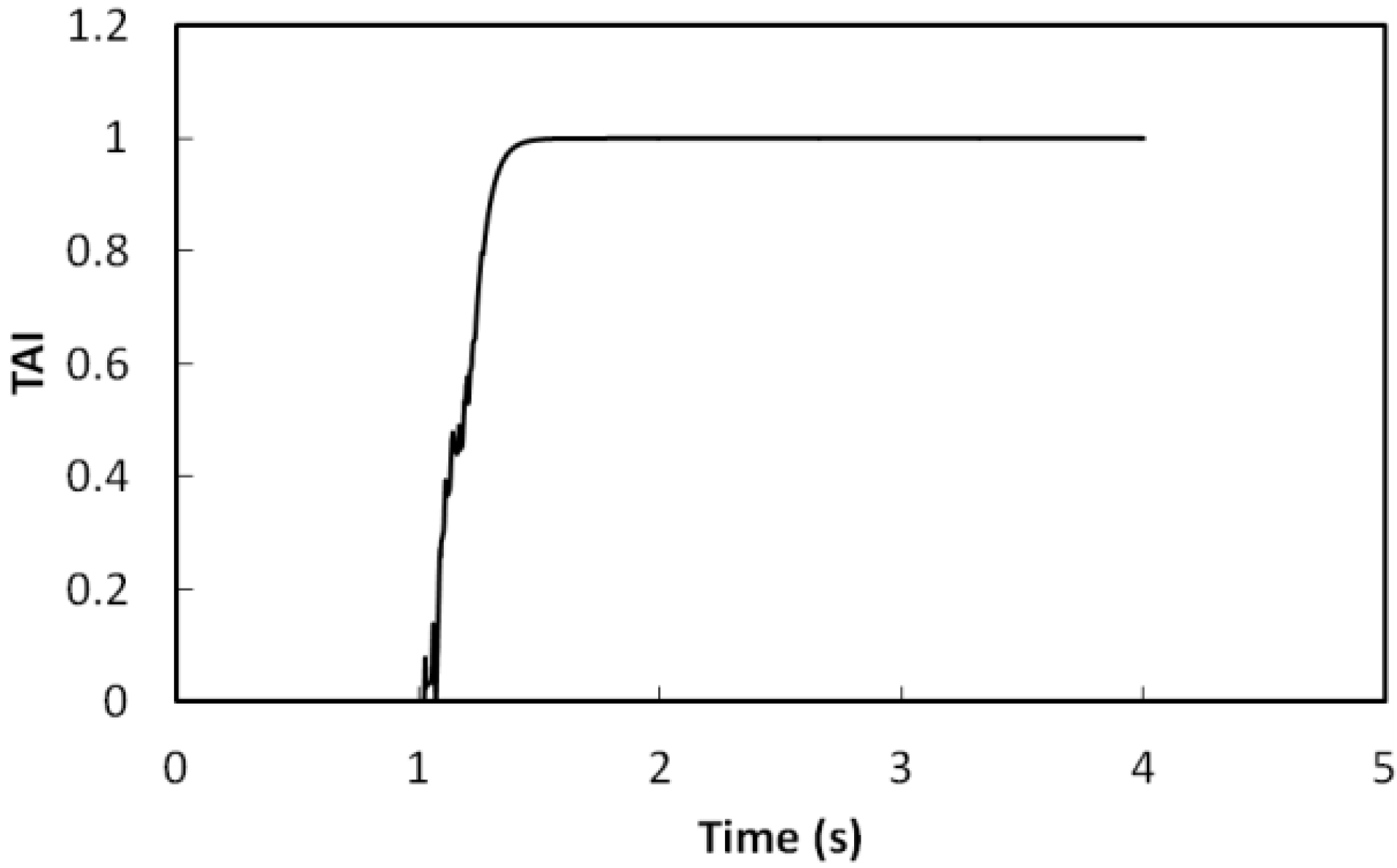
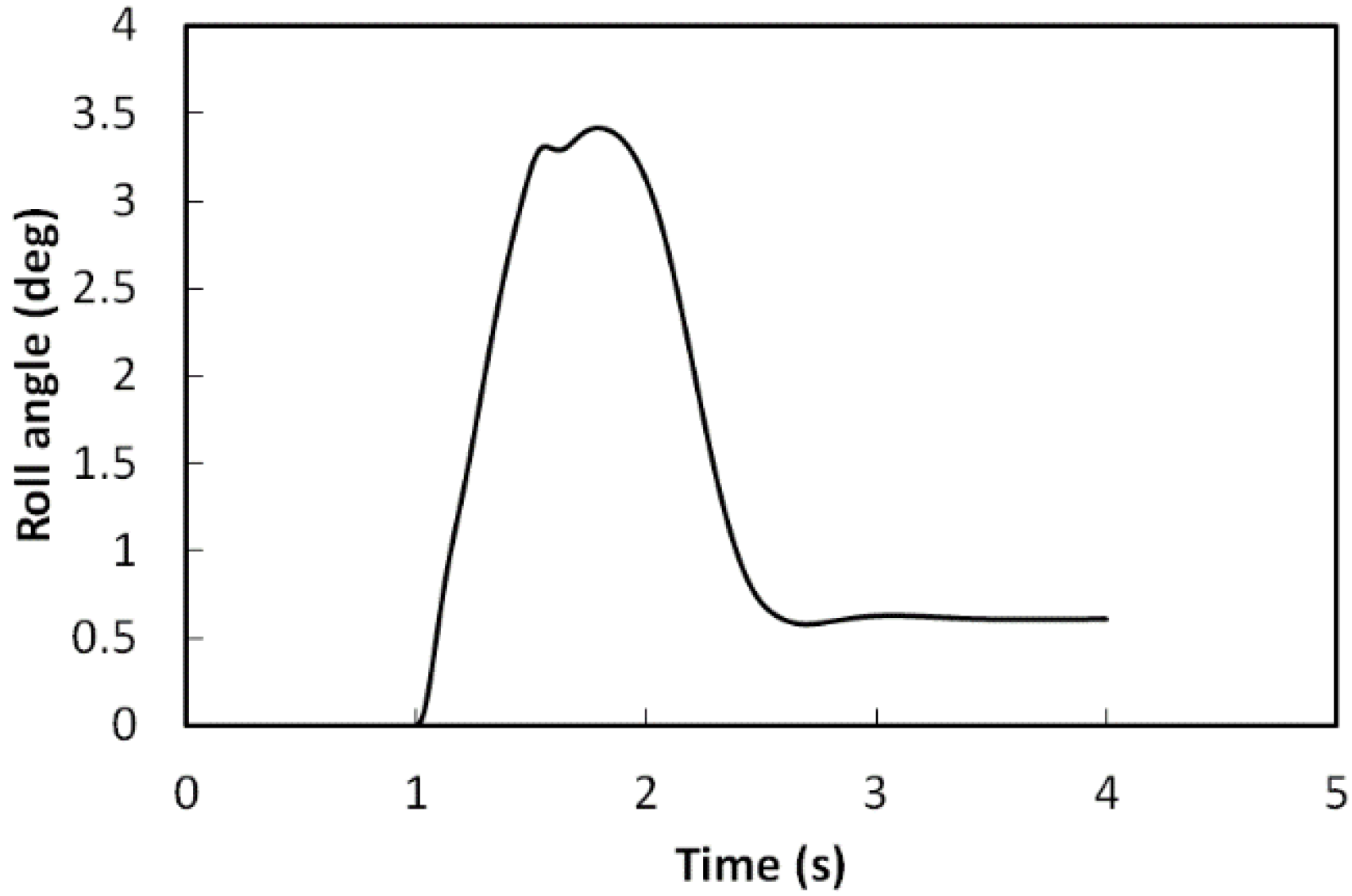
The initial speed of the vehicle is set to be 28 m/s. The torque applied to each in-wheel motor is 20 Nm. When the simulation time t reaches one second, a 30 degree steering angle to the left side is applied to the vehicle. The roll angle is shown in Figure 8, which increases to close to four degree rapidly. For the vehicle simulated, such level of the roll angle can lead to a rollover, which is dangerous and should be prevented by the controller. The TAI value shown in Figure 9 dramatically approaches to its maximum value after one second, which also implies that the roll level is out of its safety region. The lateral force of four wheels and the total lateral force are shown in Figure 10 and Figure 11, which are presented here for the comparison and analysis.
Figure 8. The roll angle.
Energies 08 02008 g008
Figure 9. The TAI.
Figure 9. The TAI.
Energies 08 02008 g009
Figure 10. The lateral tire forces. (a) Front left wheel; (b) Front right wheel; (c) Rear left wheel; (d) Rear right wheel.
Energies 08 02008 g010
Figure 11. Total lateral force.
Energies 08 02008 g011

5. Experimental Results

A picture of the in-wheel motored EV used in the experiments is shown in Figure 12a. The parameters of this EV have been used in the simulation in Section 4. The vehicle is equipped with four permanent magnet synchronous in-wheel motors (4 kilowatts each). Each of the in-wheel motors can be controlled independently. The specifications of the experimental vehicle are listed in Table 2.
Figure 12. Test vehicle. (a) Photo of the vehicle; (b) Experimental system configuration; (c) The controller design process using MicroAutoBox; (d) The ControlDesk panel.
Energies 08 02008 g012
Table 2. Specifications of the experimental vehicle.
ParametersValue/Type
Length of the body2500 mm
Width of the body1600 mm
Height of the body1400 mm
Weight400 kg
Wheel radius276 mm
Power of the motor4 kw
Voltage of the battery96 V
ControllerMicroAutoBox
The control system of the experimental vehicle is built using a dSPACE MicroAutoBox (MAB), as shown in Figure 12b. The controller design process using MAB is shown in Figure 12c. When the vehicle is running, the MAB controller is also connected to a mobile workstation. On the screen of the mobile workstation, a graphical panel is built using dSPACE ControlDesk to show the key parameters in a real-time fashion and to record the experimental data, as shown in Figure 12d.
The data of the vehicle’s physical size and the performance are imported to CarSim, as shown in Figure 13, which is industrial standard software with experimental data packages. Using CarSim, the ultimate condition and scenario of the rollover can be tested for our EV.
Figure 13. CarSim test structure.
Energies 08 02008 g013
In Figure 13, the control signals are sent to the test vehicle module in CarSim, where the rollover test runs with the data of the test EV’s physical size and performance data being integrated in the CarSim module. The test results are exported from CarSim to the controller as feedback and display signals. Special emphasis should be given to the powertrain section. In CarSim, there is no ready-to-use vehicle structure for EVs, especially for in-wheel drive EVs. Thus, a four-wheel drive powertrain type is chosen and we need to model the powertrain components all separately from the powertrain module, as shown in Figure 14. In this way, the torque applied to the four in-wheel motors can be given separately.
As in the three-level control structure discussed in Section 3, the experimental verification contains three cases: without control, with middle level control (and lower level control), and with upper level control (plus middle and lower level controls).
Figure 14. Choose all external powertrain components.
Energies 08 02008 g014

5.1. Without Control

In the experiment, the vehicle has an initial velocity of 28 m/s, the same as in the simulation. The torque applied to each in-wheel motor is again 20 Nm. The steering angle is zero at the beginning, and step up to 30 degree to the left side at one second. Without any rollover control, the roll angle increase immediately after one second and goes up to about four degree as shown in Figure 15. The corresponding TAI also deviates largely from its safety region, shown in Figure 16.
Figure 15. The roll angle without control.
Energies 08 02008 g015
Figure 16. The TAI without control.
Energies 08 02008 g016
Figure 17. The lateral tire forces without control. (a) Front left wheel; (b) Front right wheel; (c) Rear left wheel; (d) Rear right wheel.
Energies 08 02008 g017
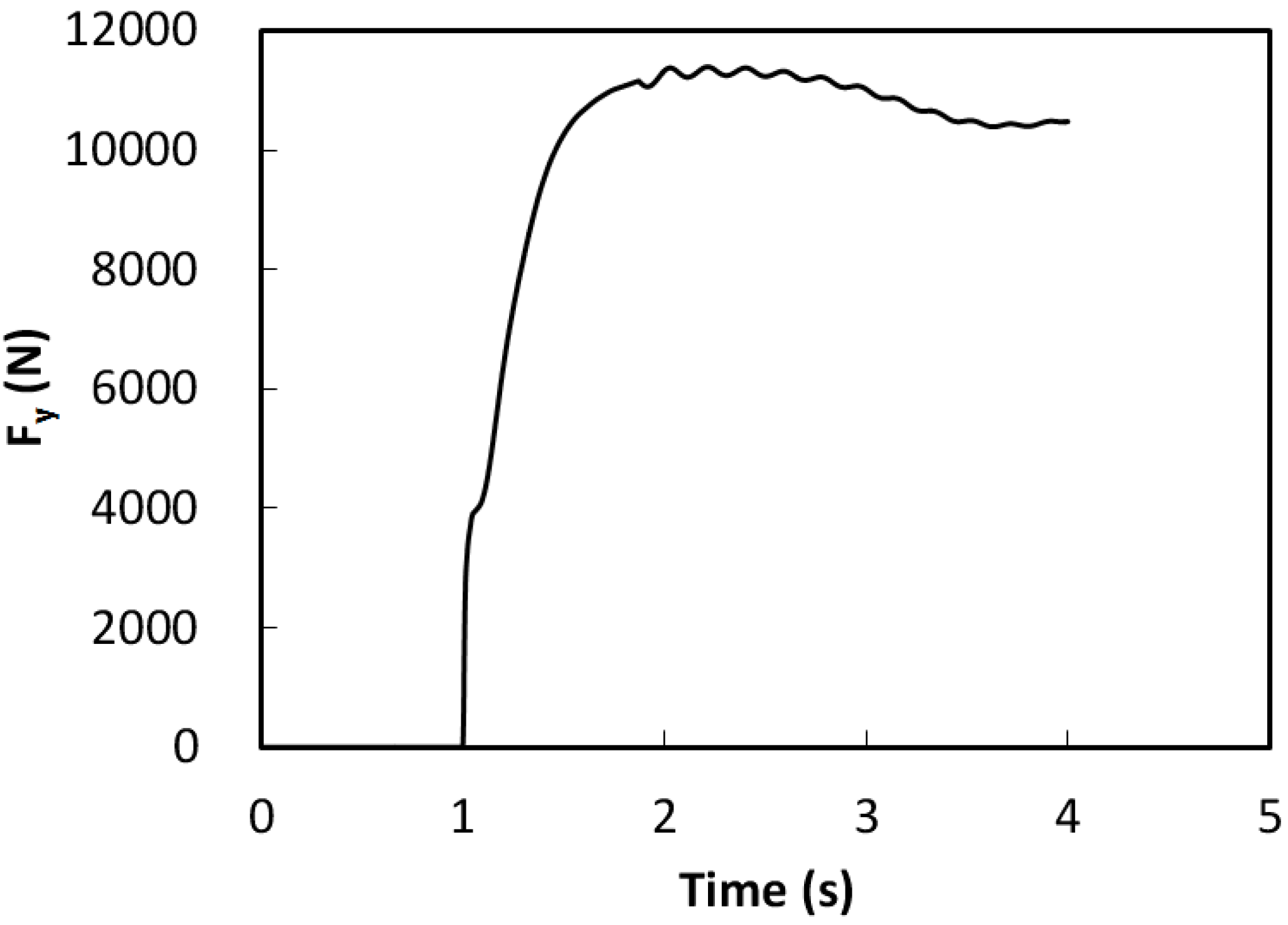
In Figure 17, the lateral tire forces of four wheels can be found, whose trends are consistent with the results from our in-house EV dynamic simulation (although those values are not exactly the same). The reason of the difference lies in that the vehicle dynamic model in the simulation is built based on basical theoretical equations, where differences with real vehicles could exist. Meanwhile, the road friction conditions in the simulation are also calculated ideally, which may not be accurate enough compared to the real world friction coefficient between road and the vehicle. The total lateral force of the vehicle is shown in Figure 18, with a stable value at around 11,000 Nm.
Figure 18. Total lateral force without control.
Energies 08 02008 g018

5.2. With Middle Level Control

As discussed earlier, in the three-level control structure of EVs, the lower level control implements only single wheel driving and braking. Thus, for the rollover prevention, one possible solution is to implement at least the middle and lower level controls. In the middle level control, the required yaw moment command is received from the upper level controller, and the total driving and braking torque allocations are calculated and decided at this level.
The same working condition is applied to the vehicle with the middle level control. The result in Figure 19 shows that the roll angle is not restricted in its safety region. It rises up just like under the condition without any rollover control. The TAI value in Figure 20 also indicates that the TAI value is not well controlled either. It increases quickly to its maximum value and remains at around one.
Figure 19. The roll angle with middle level control.
Energies 08 02008 g019
Figure 20. The TAI with middle level control.
Energies 08 02008 g020
The reasons of this result can be found in Figure 21 and Figure 22. Compared with the condition without any control, although the four-wheel lateral tire forces are redistributed at the middle level control, the total lateral force of the vehicle remains the same. It can be found in Figure 22 that the total lateral force of the vehicle is still around 11,000 Nm, the same as the case without any rollover prevention control. The total lateral force does not decrease, so the roll angle and the TAI value do not remain within their safety regions, as discussed in Section 2.1. This result clearly indicates that in order to prevent a rollover, only the middle level control itself is not enough. Therefore, the change of yaw moment command from the upper controller is required.
Figure 21. The lateral tire forces with middle level control. (a) Front left wheel; (b) Front right wheel; (c) Rear left wheel; (d) Rear right wheel.
Energies 08 02008 g021
Figure 22. Total lateral force with middle level control.
Energies 08 02008 g022

5.3. With Upper Level Control

At the upper level control, the yaw moment control target is calculated based on the driver’s command and the vehicle status. If the TAI value increases to a dangerous level, the upper level controller recalculates the yaw moment target and sends it back to the middle level. Thus, the total lateral force can decrease and the roll angle will be constrained.
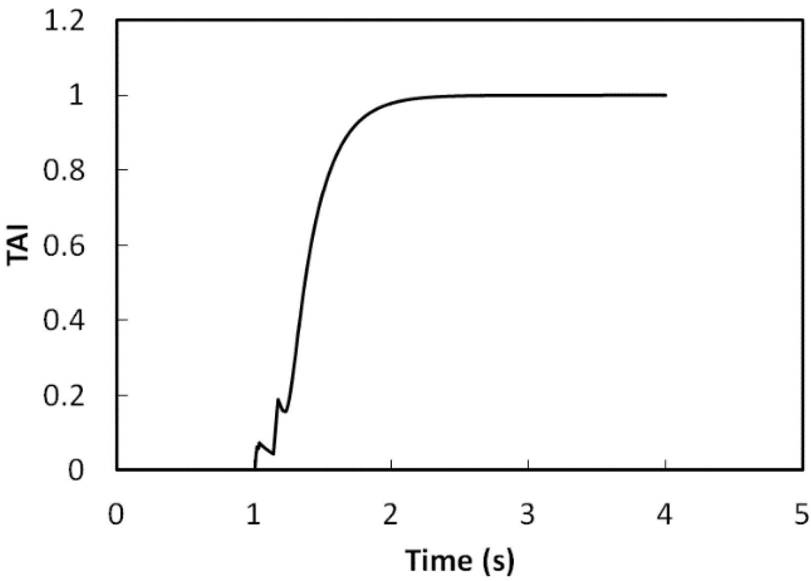
The results with the upper level control are shown in Figure 23 and Figure 24. The roll angle is beyond the safety value at the beginning when the steering angle is changed to 30 degrees at one second. Then the controller works, and the roll angle drops to a small value. The same results can be found in Figure 24 where the TAI is also well controlled. It rises up toward its maximum value in the first instance and then decreases gradually to the safety region.
Figure 23. The roll angle with upper level control.
Energies 08 02008 g023
Figure 24. The TAI with upper level control.
Energies 08 02008 g024
The lateral forces of four wheels in Figure 25 also show the redistribution and the decrease of the lateral tire forces. As shown in Figure 26, the total lateral force is constrained because of the function of the yaw moment controller at the upper level control. It proves that the rollover cannot be prevented by using the middle level control only. With the help of the upper level control, the roll angle can remain within its safety region by using the TAI method to detect the rollover. In addition, comparatively speaking, in the case of without rollover prevention, the roll movement cannot be well controlled and the vehicle will go out of the road path completely. However, with the TAI method being applied, the rollover is prevented and the vehicle can still run on the road path according to the drivers’ commands.
Figure 25. The lateral tire forces with upper level control. (a) Front left wheel; (b) Front right wheel; (c) Rear left wheel; (d) Rear right wheel.
Energies 08 02008 g025
Figure 26. Total lateral force with upper level control.
Energies 08 02008 g026

6. Conclusions

In this paper, the TA index-based rollover prevention method is proposed. The TAI method is based on a novel wheel status indicator TA for EVs, which has been proposed using both motor torque and wheel acceleration information. The three-level EV control structure is used in this paper to demonstrate the effectiveness of the proposed TAI based control method for rollover prevention. The simulation is conducted using the in-house EV dynamic model. The experimental rollover tests use the in-wheel motored EV in the authors’ lab and the industrial standard software CarSim. Both the simulation and the experimental results demonstrate that TAI is very effective in rollover prevention.
The new TAI method again proves that the superior control performance of electric motors can inherently bring advantages for EVs in the field of active safety and dynamic stability control. The authors’ future research shall include the new TA/TAI-based vehicle body slip angle estimation method and the lateral stability control of EVs.

Acknowledgments

This work was partly supported by NTN Corporation for the test vehicle. The authors would like to thank Chengbin Ma, Xiaodong Wu, Lu Liu, Bin Wang and Lei Wang for their kind guidance and help in theory development, simulation model establishment and experimental work.

Author Contributions

This paper is a result of the collaboration of all the authors. In particular, Xiang Liu and Min Xu contributed to the development of the method, Xiang Liu and Mian Li performed the simulations and experiments. Xiang Liu, Min Xu and Mian Li contributed to the results analysis and the revision of this paper.

Nomenclature

V
Vehicle longitudinal velocity
ω
Wheel angular velocity
r
Wheel equivalent radius
λ
Wheel slip ratio
T
Drive motor torque
J
Wheel inertia
g
Gravity acceleration
β
Vehicle side slip angle
γ
Yaw
lf
Distance between the vehicle center of gravity and the front axle
lr
Distance between the vehicle center of gravity and the rear axle
Cu
Cornering stiffness of the front tire
Cr
Cornering stiffness of the rear tire
α f
Slip angle of the front wheel
α r
Slip angle of the rear wheel
Mz
Direct yaw moment from the wheel torque difference
Jz
Vehicle yaw inertial
δ
Steering angle
hs
Distance between the vehicle center of gravity and the roll center of the sprung mass

Conflicts of Interest

The authors declare no conflict of interest.

References

  1. Zhou, G.; Ou, X.; Zhang, X. Development of electric vehicles use in China: A study from the perspective of life-cycle energy consumption and greenhouse gas emissions. Energy Policy 2013, 59, 875–884. [Google Scholar] [CrossRef]
  2. Wang, B.; Xu, M.; Yang, L. Study on the economic and environmental benefits of different EV powertrain topologies. Energy Convers. Manag. 2014, 86, 916–926. [Google Scholar] [CrossRef]
  3. Liu, H.; Chen, X.; Wang, X. Overview and prospects on distributed drive electric vehicles and its energy saving strategy. Prz. Elektrotech. 2012, 88, 122–125. [Google Scholar]
  4. Gu, J.; Ouyang, M.; Lu, D.; Li, J.; Lu, L. Energy efficiency optimization of electric vehicle driven by in-wheel motors. Int. J. Automot. Technol. 2013, 14, 763–772. [Google Scholar] [CrossRef]
  5. Xu, W.; Zheng, H.; Liu, Z. The Regenerative Braking Control Strategy of Four-Wheel-Drive Electric Vehicle Based on Power Generation Efficiency of Motors; SAE Technical Paper; Society of Automotive Engineers: Warrendale, PA, USA, 2013. [Google Scholar]
  6. Hori, Y. Future vehicle driven by electricity and control-research on four-wheel-motored “UOT electric march II”. IEEE Trans. Ind. Electron. 2004, 51, 954–962. [Google Scholar] [CrossRef]
  7. Liu, X.; Ma, C.; Li, M.; Xu, M. A kriging assisted direct torque control of brushless DC motor for electric vehicles. In Proceedings of the IEEE 7th International Conference Natural Computation (ICNC), Shanghai, China, 2011.
  8. Liu, X.; Li, M.; Ma, C.; Xu, M. Kriging assisted on-line torque calculation for brushless DC motors used in electric vehicles. In Proceedings of the IEEE International Symposium Conference on Industrial Electron (ISIE), Hangzhou, China, 2012.
  9. Liu, X.; Li, M.; Xu, M. Kriging assisted on-line torque calculation for brushless DC motors used in electric vehicles. IEEE Trans. Veh. Technol. 2014. under review. [Google Scholar]
  10. Long, B.; Lim, S.T.; Ryu, J.H.; Chong, K.T. Energy-regenerative braking control of electric vehicles using three-phase brushless direct-current motors. Energies 2014, 7, 99–114. [Google Scholar] [CrossRef]
  11. Liu, X.; Li, M.; Xu, M. A new anti-skid control method for electric vehicles using motor torque and wheel acceleration. Proc. Inst. Mech. Eng. Part. D 2014. under review. [Google Scholar]
  12. Geng, C.; Mostefai, L.; Denai, M.; Hori, Y. Direct yaw-moment control of an in-wheel-motored electric vehicle based on body slip angle fuzzy observer. IEEE Trans. Ind. Electron. 2009, 56, 1411–1419. [Google Scholar] [CrossRef] [Green Version]
  13. Zhang, D.; Liu, G.; Zhao, W.; Miao, P.; Jiang, Y.; Zhou, H. A neural network combined inverse controller for a two-rear-wheel independently driven electric vehicle. Energies 2014, 7, 4614–4628. [Google Scholar] [CrossRef]
  14. Nguyen, B.; Wang, Y.; Fujimoto, H.; Hori, Y. Lateral stability control of electric vehicle based on disturbance accommodating kalman filter using the integration of single antenna GPS receiver and yaw rate sensor. J. Electr. Eng. Technol. 2013, 8, 899–910. [Google Scholar] [CrossRef]
  15. De Novellis, L.; Sorniotti, A.; Gruber, P.; Pennycott, A. Comparison of feedback control techniques for torque-vectoring control of fully electric vehicles. IEEE Trans. Veh. Technol. 2014, 63, 3612–3623. [Google Scholar] [CrossRef]
  16. Xu, G.; Li, W.; Xu, K.; Song, Z. An intelligent regenerative braking strategy for electric vehicles. Energies 2011, 4, 1461–1477. [Google Scholar] [CrossRef]
  17. Pennycott, A.; de Novellis, L.; Gruber, P.; Sorniotti, A. Optimal braking force allocation for a four-wheel drive fully electric vehicle. Proc. Inst. Mech. Eng. Part I 2014, 228, 621–628. [Google Scholar]
  18. Pennycott, A.; de Novellis, L.; Sabbatini, A.; Gruber, P.; Sorniotti, A. Reducing the motor power losses of a four-wheel drive, fully electric vehicle via wheel torque allocation. Proc. Inst. Mech. Eng. Part D 2014, 228, 830–839. [Google Scholar] [CrossRef]
  19. Ma, C.; Xu, M.; Wang, H. Dynamic emulation of road/tyre longitudinal interaction for developing electric vehicle control systems. Veh. Syst. Dyn. 2011, 49, 433–447. [Google Scholar] [CrossRef]
  20. Cai, Z.; Ma, C.; Zhao, Q. Acceleration-to-torque ratio based anti-skid control for electric vehicles. In Proceedings of the IEEE/ASME International Conference on Mechatronic and Embedded Systems and Application, Qingdao, China, 15–17 July 2010.
  21. Phanomchoeng, G.; Rajamani, R. Real-time estimation of rollover index for tripped rollovers with a novel unknown input nonlinear observer. IEEE/ASME Trans. Mechatron. 2014, 19, 743–754. [Google Scholar] [CrossRef]
  22. Rajamani, R.; Piyabongkarn, D. New paradigms for the integration of yaw stability and rollover prevention functions in vehicle stability control. IEEE Trans. Intell. Trans. Syst. 2013, 14, 249–261. [Google Scholar] [CrossRef]
  23. Yoon, J.; Kim, D.; Yi, K. Design of a rollover index-based vehicle stability control scheme. Veh. Syst. Dyn. 2007, 45, 459–475. [Google Scholar] [CrossRef]
  24. Piyabongkarn, D.; Lew, J.Y.; Rajamani, R.; Grogg, J.A. Active driveline torque-management systems. IEEE Control Syst. Mag. 2010, 30, 86–102. [Google Scholar] [CrossRef]
  25. Solmaz, S.; Corless, M.; Shorten, R. A methodology for the design of robust rollover prevention controllers for automotive vehicles with active steering. Int. J. Control. 2007, 80, 1763–1779. [Google Scholar] [CrossRef]
  26. Rajamani, R. Vehicle Dynamics and Control, 2nd ed.; Springer-Verlag: New York, NY, USA, 2012. [Google Scholar]
  27. Bevly, D.M.; Ryu, J.; Gerdes, J.C. Integrating INS sensors with GPS measurements for continuous estimation of vehicle sideslip, roll, and tire cornering stiffness. IEEE Trans. Intell. Trans. Syst. 2006, 7, 483–493. [Google Scholar] [CrossRef]
  28. Ko, S.Y.; Ko, J.W.; Lee, S.M.; Cheon, J.S.; Kim, H.S. Vehicle velocity estimation using effective inertia for an in-wheel electric vehicle. Int. J. Automot. Technol. 2014, 15, 815–821. [Google Scholar]
  29. Bayar, K.; Wang, J.; Rizzoni, G. Development of a vehicle stability control strategy for a hybrid electric vehicle equipped with axle motors. Proc. Inst. of Mech. Eng. Part D 2012, 226, 795–814. [Google Scholar] [CrossRef]
  30. Kang, J.; Yoo, J.; Yi, K. Driving control algorithm for maneuverability, lateral stability, and rollover prevention of 4WD electric vehicles with independently driven front and rear wheels. IEEE Trans. Veh. Technol. 2011, 60, 2987–3001. [Google Scholar] [CrossRef]
  31. Baffet, G.; Charara, A.; Lechner, D.; Thomas, D. Experimental evaluation of observers for tire–road forces, sideslip angle and wheel cornering stiffness. Veh. Syst. Dyn. 2008, 46, 501–520. [Google Scholar] [CrossRef]
  32. Abe, M. Vehicle Handling Dynamics: Theory and Application; Butterworth-Heinemann: Oxford, UK, 2009. [Google Scholar]
  33. Mitschke, M.; Wallentowitz, H. Dynamik der Kraftfahrzeuge; Chinese Version; Tsinghua University Press: Beijing, China, 2009. [Google Scholar]
  34. Pacejka, H.B.; Bakker, E. The magic formula tyre model. Veh. Syst. Dyn. 1992, 21, 1–18. [Google Scholar] [CrossRef]
  35. Pacejka, H.B. Tyre and Vehicle Dynamics; Butterworth-Heinemann: Oxford, UK, 2005. [Google Scholar]