
Pyroelectric Harvesters for Generating Cyclic Energy


Department of Mechanical Design Engineering, National Formosa University, No. 64, Wunhua Rd., Huwei Township, Yunlin County 632, Taiwan
*
Author to whom correspondence should be addressed.
Energies 2015, 8(5), 3489-3502; https://doi.org/10.3390/en8053489
Submission received: 10 February 2015
/
Revised: 6 April 2015
/
Accepted: 21 April 2015
/
Published: 27 April 2015
(This article belongs to the Special Issue Thermoelectric Energy Harvesting)
Abstract
:Pyroelectric energy conversion is a novel energy process which directly transforms waste heat energy from cyclic heating into electricity via the pyroelectric effect. Application of a periodic temperature profile to pyroelectric cells is necessary to achieve temperature variation rates for generating an electrical output. The critical consideration in the periodic temperature profile is the frequency or work cycle which is related to the properties and dimensions of the air layer; radiation power and material properties, as well as the dimensions and structure of the pyroelectric cells. This article aims to optimize pyroelectric harvesters by matching all these requirements. The optimal induced charge per period increases about 157% and the efficient period band decreases about 77%, when the thickness of the PZT cell decreases from 200 μm to 50 μm, about a 75% reduction. Moreover, when using the thinner PZT cell for harvesting the pyroelectric energy it is not easy to focus on a narrow band with the efficient period. However, the optimal output voltage and stored energy per period decrease about 50% and 74%, respectively, because the electrical capacitance of the 50 μm thick pyroelectric cell is about four times greater than that of the 200 μm thick pyroelectric cell. In addition, an experiment is used to verify that the work cycle to be able to critically affect the efficiency of PZT pyroelectric harvesters. Periods in the range between 3.6 s and 12.2 s are useful for harvesting thermal cyclic energy by pyroelectricity. The optimal frequency or work cycle can be applied in the design of a rotating shutter in order to control the heated and unheated periods of the pyroelectric cells to further enhance the amount of stored energy.
1. Introduction
Energy harvesting is the process of converting, processing and storing environmental energy. The ambient energy comes in the form of wind, water, sun, heat, etc. Energy harvesting is also called energy scavenging, and it is employed for recovering energy that otherwise would be wasted. Sources for energy harvesting are mainly categorized as mechanical, thermal and solar energy. A significant amount of waste heat is lost as a by-product of power, refrigeration, or heat pump cycles. Direct energy conversion using thermoelectric generators mainly relies on the Seebeck effect to convert a steady-state temperature difference between two dissimilar metals or semiconductors into electrical energy. Thermoelectric generators need a temperature difference, as they cannot work in an environment with spatially uniform and time-dependent temperature fluctuations [1]. Alternatively, pyroelectric devices directly convert temperature fluctuations into electrical energy [1,2,3,4,5,6,7]. Pyroelectric materials have the potential to operate with high thermodynamic efficiency and, compared to thermoelectric generators, do not require bulky heat sinks to maintain the temperature gradient. Pyroelectric materials respond to changes in temperature which cause an internal strain, and this, in turn, results in electrical charges on the material’s surface. Advances in materials and in thermal-electrical cycling methods are expected to provide low cost and high-power-density electrical generators [8]. When a pyroelectric element is subjected to a power density radiation (W) causing a temperature variation (dT), the induced charge (dQ, units: μC) is released by the electrode area (A) of the element due to a decrease in polarization, as presented by [1,9]:
where η is the absorption coefficient of radiation; A is the electrode area; dT/dt is the temperature variation rate of the pyroelectric materials; Q is the induced charge; and P (units: μCm−2K−1) is the pyroelectric coefficient of the pyroelectric materials, as presented by [1,9]:
where Ps is the magnitude of the electrical polarization vector. Pyroelectric elements, such as flat-plate capacitors, are sandwiched in between the top and bottom electrodes, and poled along the axis perpendicular to the plates. Ps is perpendicular to the electrode surface and its magnitude equals the electrode charge density. Therefore, pyroelectric elements with high P values and applications with large temperature variations over time should be considered. Moreover, increasing the electrode area will result in enhanced current under parity of incident thermal power density per unit area. When the dimensions and the materials of pyroelectric elements are determined, creating a larger temperature variation rate in the pyroelectric element is useful for harvesting pyroelectric energy, however, the temperature variation rate is difficult to extract from pyroelectric layers by experimental measurements. Some finite element models were built using the commercial software package COMSOL to explore the temperature variation rate in pyroelectric cells, with some designs of cavities created by wet etching, trenches made with a precision dicing saw, and grooves generated by a sandblast etching technique, in order to improve the energy conversion efficiency of PZT cells by pyroelectricity [5,6,7].
dQ = η × P × A × dT
P = dPs/dT
Cyclic heat energy harvesting mainly uses the pyroelectric elements to convert temperature fluctuations into electricity. Periodic heating leads to continuous power generation over time, and provides a means of continuously harvesting energy. Therefore, it was necessary to design a periodic temperature profile and apply it to the pyroelectric elements to generate temperature variation rates. The factors affecting the periodic temperature profiles for improving the temperature variation rate in pyroelectric elements include the frequency or work cycle, radiation power, properties and dimensions of the air layer, and the material properties, dimensions and structure of the pyroelectric elements, etc. This research proposes a complete analysis of all these factors for a thorough comprehension of the relationships among the abovementioned considerations.
2. Materials and Methods
2.1. Cyclic Heating System for Pyroelectricity
A commercial PZT pyroelectric cell with the dimensions of 9 mm × 9 mm × 0.214 mm was used. The cell comprised a 0.2 mm thick PZT sheet sandwiched between a top and a bottom electrode. The electrodes were 7 μm thick silver films. PZT samples were provided by Eleceram Technology Co. (Taoyuan, Taiwan). Table 1 shows the material properties of the commercial PZT pyroelectric cell. A thick PZT sheet with a low electrical capacitance is more likely to generate higher voltages than a thin PZT film with a high electrical capacitance under a given temperature variation [1], but a thick pyroelectric material has high thermal capacity, which hinders quick temperature variations. Obviously, thin pyroelectric materials have a high temperature variation rate. Although thin film deposition technology can be used to grow films with lesser thickness, the pyroelectric properties usually decrease quickly. Commercial PZT bulk materials possessing excellent pyroelectric properties, together with the designs of trench and groove structures fabricated using a dicing saw apparatus, as well as a sandblast etching technique, were useful for improving the temperature variation rate and thus enhancing the efficiency of pyroelectric harvesters [6,7].

| Sample ID | Thickness (μm) | Area (mm2) | Size (mm × mm) | Relative dielectric constant (ε33T/ε0) | Density (g/cm3) | Poling field (V/μm) | Pyroelectric coefficient (10−4cm−2K−1) |
|---|---|---|---|---|---|---|---|
| KA | 200 | 81 | 9 × 9 | 2100 | 7.9 | 3.5 | 6.97 |
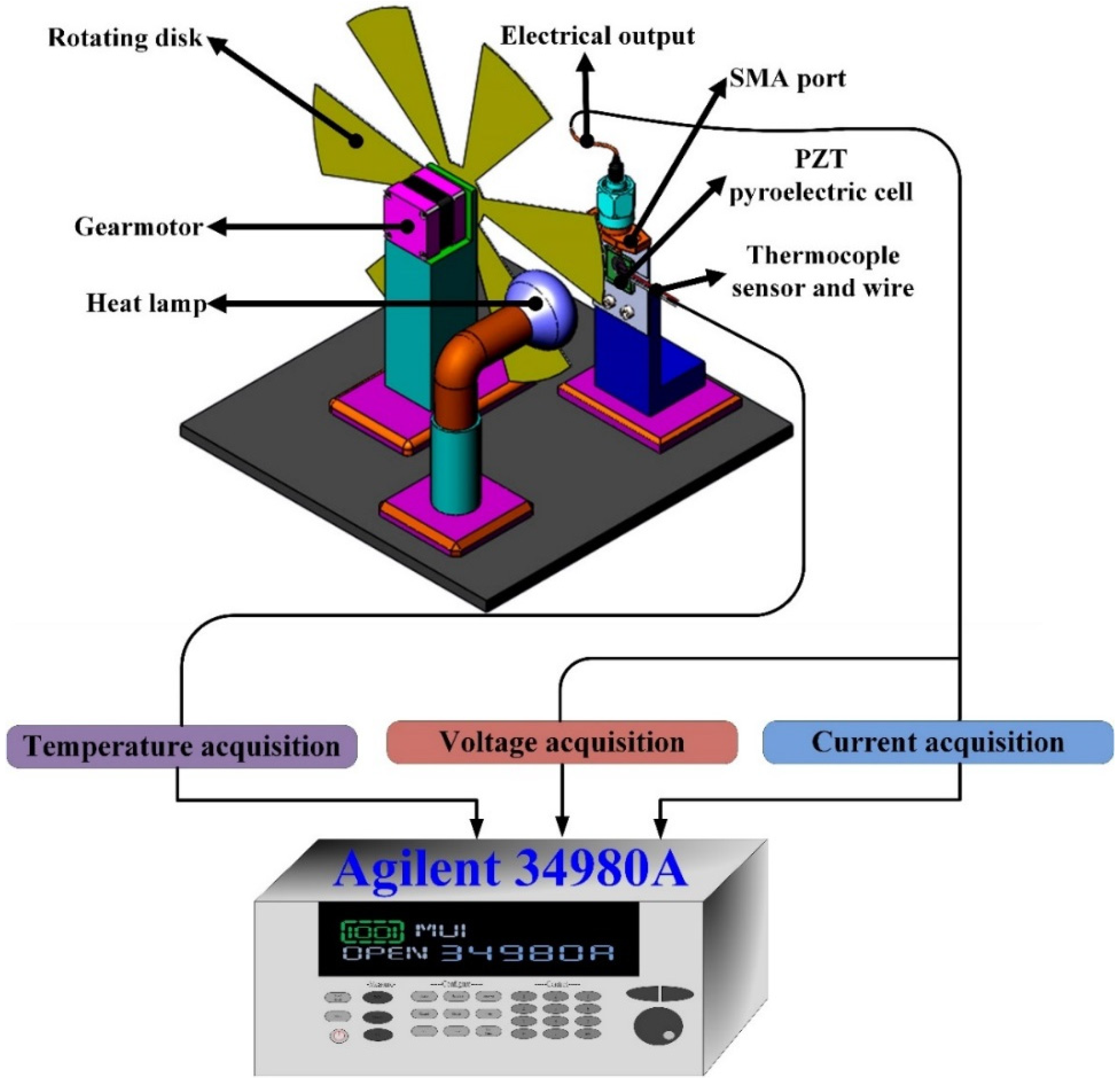
The cyclic heating system was mainly meant to achieve a periodic temperature profile for generating temperature fluctuations in the pyroelectric cells. Figure 1 shows a schematic diagram of a pyroelectric harvester for generating cyclic heat energy and the measurement setup. This system consisted of a rotating disk with apertures, a gear motor, a radiating heat lamp (Heat Plus 250W 110V, Philips, Amsterdam, The Netherlands), thermocouple sensors and the PZT pyroelectric cells placed on a printed circuit board (PCB). A cavity was dug on the PCB to hold the PZT cell along the edges in order to expose it completely to the air. The distance between the heat lamp and the PZT cell was about 15 cm. The rotating speed of the disk could be changed by controlling the voltage applied to the gear motor. Type K (Chromel/Alumel) thermocouple sensors were used to probe the temperature variations in the pyroelectric cells; they were attached to the bottom electrode at the center of the PZT cell, thereby ensuring good thermal contact.
Figure 1.
Schematic diagram of the pyroelectric harvester with cyclic heating and measurement setup.
Figure 1.
Schematic diagram of the pyroelectric harvester with cyclic heating and measurement setup.

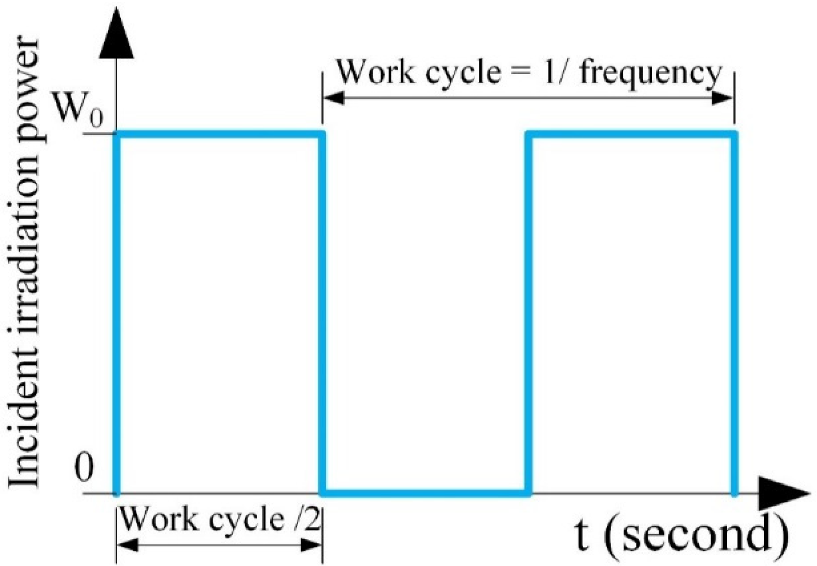
The PZT pyroelectric cells with thermocouple sensors were attached to the PCB for measuring the electrical outputs via the SMA connectors. The radiating heat lamp was the heat source; it was projected onto the PZT pyroelectric cells through the apertures of the disk. Therefore, the disk could prevent the PZT cells from absorbing the heat from the radiating heat lamp, except for the apertures in the disk. When the disk rotated, the PZT cells were periodically heated. Finally, the output data of temperature, current and voltage were measured simultaneously with a computer-controlled data acquisition apparatus (Agilent 34980A, Santa Clara, CA, USA). The variables in the periodic temperature profiles included the frequency or work cycle, properties and dimensions of the air layer, material properties, and the dimension and structure of the pyroelectric PZT cells. The work cycle was defined as the heated and unheated periods of the pyroelectric cells, as depicted in Figure 2.
Figure 2.
The incident radiation power with a work cycle applied to the PZT cells.

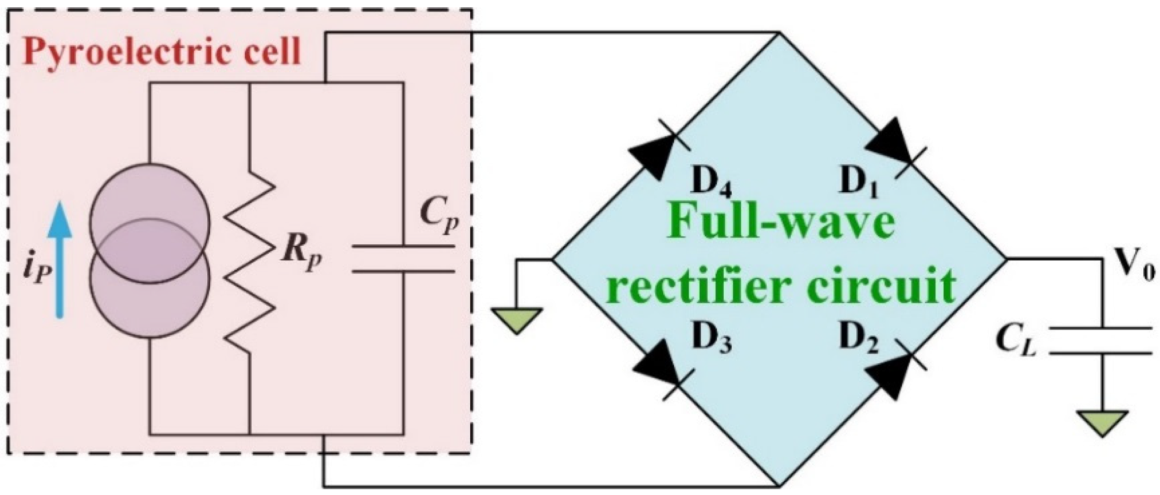
Moreover, the charge generated from thermal oscillations was stored in a capacitor CL as a storage element using the full-wave rectifier circuit, as depicted in Figure 3. The measured forward voltage drop of the diodes (Model 1N4148, IHS, Englewood, CO, USA) was 0.62 V. CL was a 4.7 μF electrolytic capacitor with a 50 V maximum voltage. During the heating cycle, the two forward-biased diodes (D1 and D3) allowed the generated current flow iP through to charge CL. The other diodes (D2 and D4) were reverse-biased, and blocked the current flow. During the cooling cycle, the direction of iP was reversed, and CL was charged through D2 and D4. The temperature in the PZT sheets and the output voltage of the circuit (V0) were also measured with the Agilent 34980A data acquisition unit.
Figure 3.
Full-wave rectifier circuit used to store the induced charge from the pyroelectric cell.

2.2. Simulation of Pyroelectric Harvesters from Cyclic Temperature Fluctuations
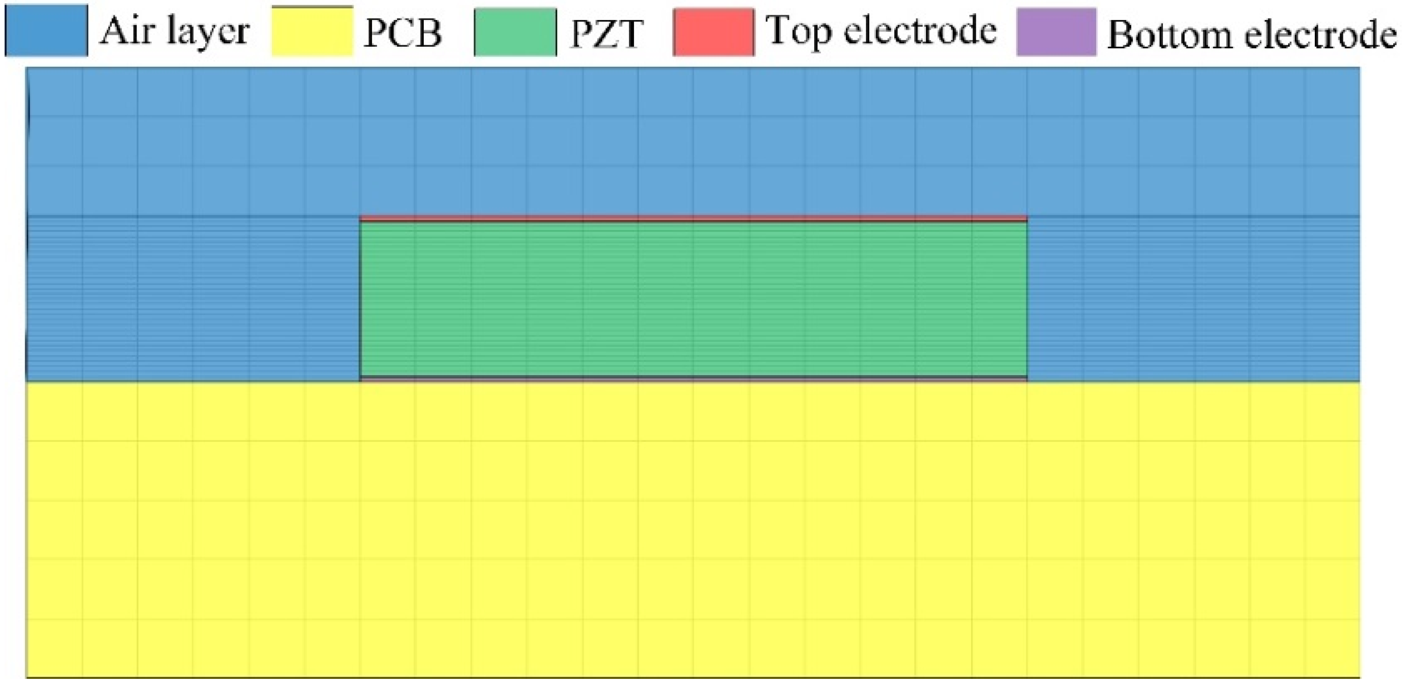
When the dimensions and materials of the pyroelectric cells are settled, the performance of the pyroelectric harvesting system can be estimated by means of the temperature variation rate of the pyroelectric cells. However, the difficulty is in extracting the temperature variation rate along the thickness direction of the pyroelectric cells. The transient temperature field in the cells is also not easy to extract by means of experimental measurements. In the present study, a two-dimensional finite element model was generated by commercial multiphysics software COMSOL Multiphysics®4.2 to explore the temperature variation rates in the PZT pyroelectric cells with various considerations. These considerations were derived from the frequency or work cycle, radiation power, properties and dimensions of the air layer, and the material properties, dimensions and structure of the pyroelectric PZT cells. The periods of rising and dropping temperature in the PZT pyroelectric cell determined the electrical output of the pyroelectric harvester, which was affected by the thermal capacity and electrical capacitance of the PZT pyroelectric cells. The various angular velocities of the disk and dimensions of the aperture determine the work cycles, resulting in the periods of rising and dropping temperature in the PZT pyroelectric cells. The distance between the PZT pyroelectric cells and the radiating heat lamp could determine the heat flux applied on the PZT cells. The dimensions and structure of the pyroelectric PZT cells could set the thermal capacity and electrical capacitance of the PZT pyroelectric cells. Hence, the performance of pyroelectric harvesters could be optimized by matching the conditions related to the various angular velocities of the disk, dimensions of the aperture, and distances between the PZT pyroelectric cells and the radiating heat lamp, when a PZT pyroelectric cell with constant dimensions and material is adopted. The thermal properties of the materials used in the numerical analysis model are listed in Table 2. There was an isotropic and time-independent assumption regarding the PZT cell, the electrodes and the PCB in the model. The thermal conductivity, heat capacity and air density were all temperature-dependent material properties, which were according to the settings in the COMSOL software. The model was meshed by regular mesh, as shown in Figure 4. Furthermore, thermal isolation was applied to the rear side of the PZT pyroelectric cells, and the two lateral sides of the model were symmetric, in order to serve as boundary conditions. The top border of the model was applied to the incident irradiation power of about 1.228 × 10⁻¹² W/μm2 [5,6,7], with various unit step functions for the resulting various frequencies or work cycles.
| Material | Thermal conductivity (Wm−1K−1) | Specific heat (Jg−1K−1) | Density (gcm−3) | Thickness (mm) |
|---|---|---|---|---|
| PCB | 0.12 | 1.38 | 0.51 | 0.4 |
| Silver electrode | 429 | 0.235 | 10.53 | 0.007 |
| PZT cell | 2.1 | 0.36 | 7.9 | 0.2 and 0.05 |
| Air | TC(T) | SH(T) | DS(T) | 0.2 |
Note: (T: Absolute temperature); TC(T) = −0.00227583562 + 1.15480022 × 10⁻⁴ × T − 7.90252856 × 10⁻⁸ × T2 + 4.11702505 × 10⁻¹¹ × T3 − 7.43864331 × 10⁻¹⁵ × T4; SH(T) = 1.04763657 − 3.72589265 × 10⁻⁴ × T + 9.45304214 × 10⁻⁷ × T2 − 6.02409443 × 10⁻¹⁰ × T3 + 1.2858961 × 10⁻¹³ × T4; DS(T) = 101.325 × 103 × 0.02897/8.314/T.
Figure 4.
Regular meshed finite element model for the PZT pyroelectric harvester.

In fact, the PZT pyroelectric cells used the current responsivity and induced charge in the performance of the harvesters. Hence, the current responsivity and induced charge were calculated from the transient temperature fields, so as to estimate the electrical outputs of the harvesters, and for further evaluating the output voltage and stored energy in a load capacitor. Moreover, the dynamic pyroelectric response current (ip, unit: μA) produced by the induced charge can be expressed as [1,9]:
ip = η × P × A × dT/dt
Moreover, the induced charge (Q, unit: μC) can be expressed as:
Finally, the current and induced charge resulting from the cyclic temperature fluctuations were rectified and stored in a 1 μF load capacitor (CL), using the full-wave rectifier circuit depicted in Figure 3. Then, the output voltage of the stored capacitor (V0) across CL and the stored energy would increase. Cuadras et al. [1] derived V0 as:
where Qleak is the charge leakage; VD is the voltage drop across the diodes when forward biased; CP is the electrical capacitance of the pyroelectric cell and N is the heating/cooling cycle. When N approaches infinity; V0 converges to:
Assuming CL > CP, and considering the forward voltage drop of the diode of 0.62 V and no leakage current, V0, max (unit: V) can be expressed as:
It is obvious that V0, max does not depend on CL, but only the internal capacitance of the pyroelectric cell (CP). The stored energy (EC, unit: nJ) in CL can be expressed as:
The relative conditions for calculating the current (ip), induced charge (Q), output voltage of the stored capacitor (V0) and stored energy (EC) are shown in Table 3.
| P (10−4 C/m2·K) | A (mm2) | CL (μF) | η (Unit Free) |
|---|---|---|---|
| 6.97 | 81 | 1 | 1 |
3. Results and Discussion
The cyclic heating system was designed to periodically heat and cool the pyroelectric elements to produce periodic temperature changes and thus harvest the resulting pyroelectric energy. With cyclic heating, the temperature changes were smaller; however, the total energy harvested could accumulate and become larger over time [10]. The present study is focused on optimizing the efficiency of PZT pyroelectric harvesters with consideration of the frequency or work cycle, radiation power, properties and dimensions of the air layer, and the dimensions and structure of the pyroelectric PZT cells.
The temperature variation rate increased when the point approached the top side of the ZnO layer because incident radiation power approached the top electrode. Using the temperature variation rate at the point near the top electrode could not discriminate the properties of the pyroelectric sensors with various thicknesses of the ZnO films. Therefore, a conservative consideration was to adopt the properties at the point near the bottom electrode for inspecting the sensors because the temperature variation rate at this point could display differences of the ZnO films with various thicknesses [5,6]. As the ZnO films at the point near the bottom electrode possess the lowest temperature variation rates, this position could certainly enhance the responsivity of the pyroelectric devices. Hence, the temperature variation rates of the ZnO films at the point near the bottom electrode were adopted to calculate the current responsivity and estimate the induced charge.
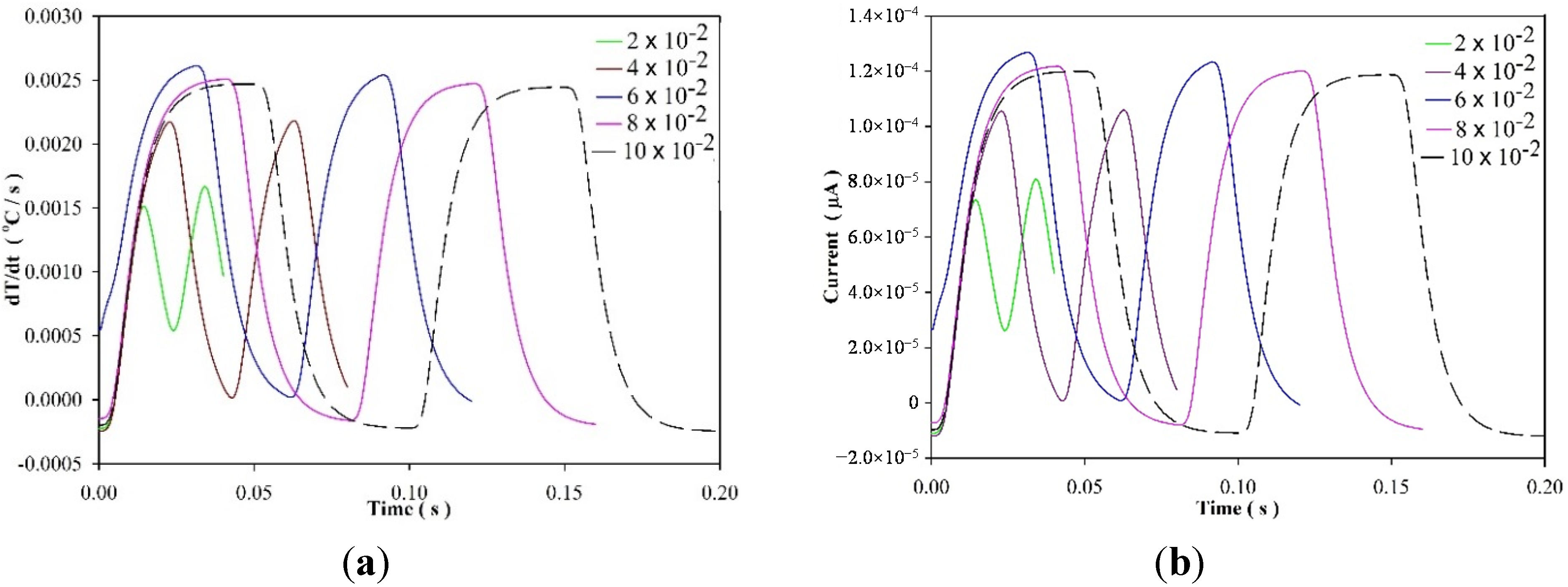
Figure 5 shows the relationships among the temperature variation rate, the current and time at five periods of 2 × 10⁻² s, 4 × 10⁻² s, 6 × 10⁻² s, 8 × 10⁻² s and 10 × 10−2 s when a 200 μm thick PZT cell used. The current curve was calculated from the temperature variation rate data. Therefore, the shapes of the curves related to the current and temperature variation rate were almost identical. It was also obvious that these curves had the best performance for the period of about 6 × 10⁻² s.
Figure 5.
Relationships among the temperature variation rate (a); the current (b) and time at five periods of 2 × 10⁻² s, 4 × 10⁻² s, 6 × 10⁻² s, 8 × 10⁻² s and 10 × 10−2 s for the 200 μm thick PZT cell used.
Figure 5.
Relationships among the temperature variation rate (a); the current (b) and time at five periods of 2 × 10⁻² s, 4 × 10⁻² s, 6 × 10⁻² s, 8 × 10⁻² s and 10 × 10−2 s for the 200 μm thick PZT cell used.

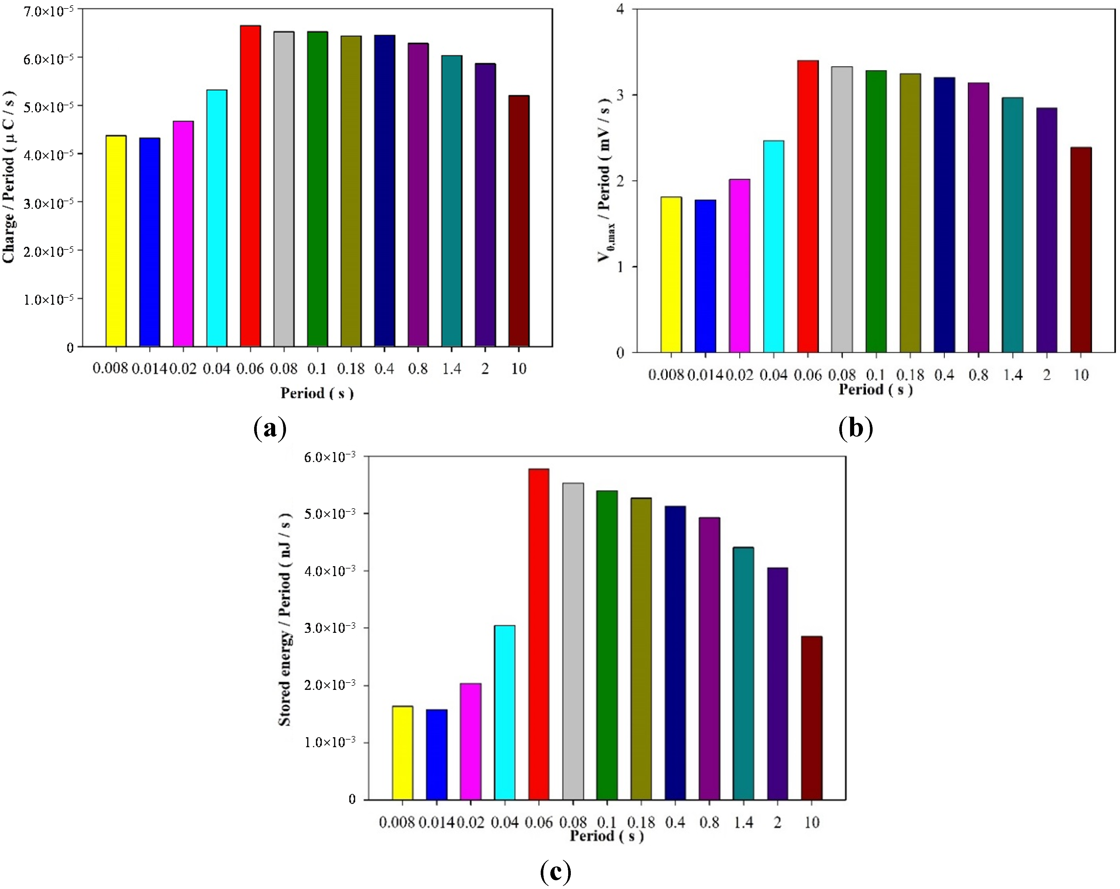
The charge was inferred from the integration of the area under the current curves by a numerical integration of Simpson’s rule. Figure 6 shows the relationships between the induced charge per period, the output voltage per period, the stored energy per period and various periods when the 200 μm thick PZT cell was used to construct the model for estimating the efficiency of pyroelectric harvesters. The induced charge per period, the output voltage per period and the stored energy per period were the largest when the work cycle or the period approached 6 × 10⁻² s. Moreover, a larger period over 6 × 10⁻² s proved more beneficial for harvesting the pyroelectric energy than a smaller period under 6 × 10⁻² s because the 200 μm thick PZT cell needed sufficient time to absorb and conduct the incident radiation power. A smaller period under 6 × 10⁻² s would reduce the thermal energy absorbed in the PZT cell. However, a much larger period over 6 × 10⁻² s rapidly reduced the pyroelectric energy harvesting because the temperature variation rate rapidly decreased and the period quickly increased.
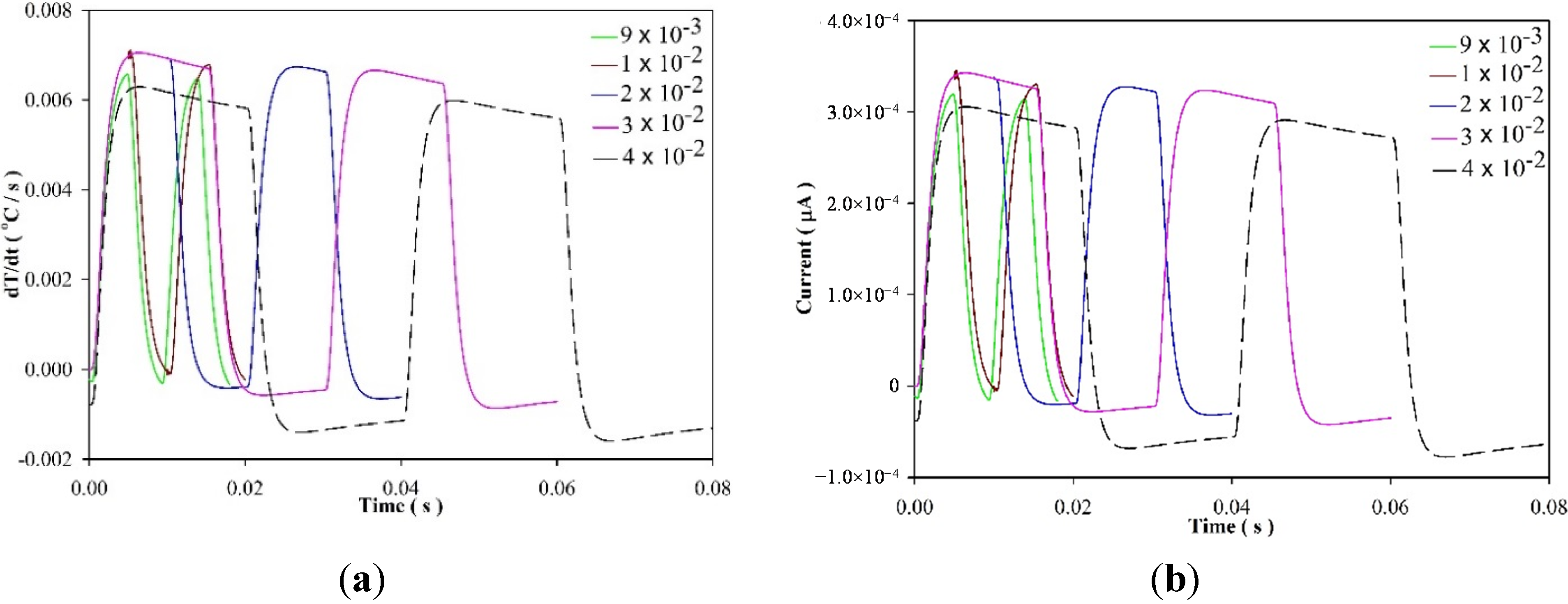
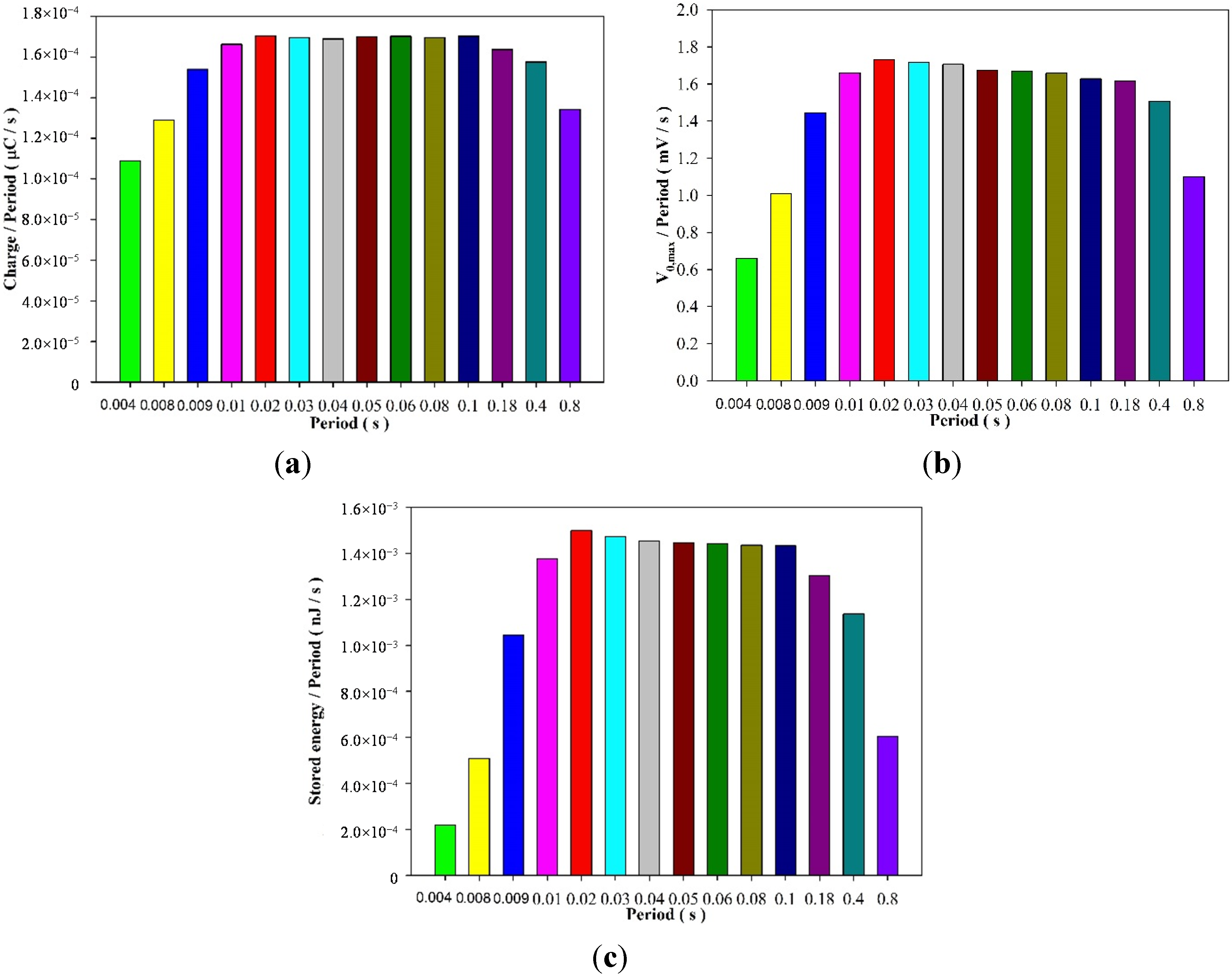
Figure 7 shows the relationships among the temperature variation rate, the current and time at five periods of 9 × 10⁻³ s, 1 × 10⁻² s, 2 × 10⁻² s, 3 × 10⁻² s and 4 × 10⁻² s for the 50 μm thick PZT cell used. Figure 8 shows the relationships between the induced charge per period, the output voltage per period, the stored energy per period and various periods when the 50 μm thick PZT cell was used. The induced charge per period, the output voltage per period and the stored energy per period were the largest when the work cycle or the period approached 2 × 10⁻² s. The optimal period for harvesting the pyroelectric energy was reduced when the thickness of the PZT cell decreased. The induced charge per period, the output voltage per period and the stored energy per period were greatly reduced over the period of 0.8 s.
Figure 6.
Relationships among (a) the induced charge per period; (b) the output voltage per period; (c) the stored energy per period and various periods for the 200 μm thick PZT cell used for constructing the analysis model.
Figure 6.
Relationships among (a) the induced charge per period; (b) the output voltage per period; (c) the stored energy per period and various periods for the 200 μm thick PZT cell used for constructing the analysis model.

Figure 7.
Relationships among (a) the temperature variation rate; (b) the current and time at five periods of 9 × 10⁻³ s, 1 × 10⁻² s, 2 × 10⁻² s, 3 × 10⁻² s and 4 × 10⁻² s for the 50 μm thick PZT cell used.
Figure 7.
Relationships among (a) the temperature variation rate; (b) the current and time at five periods of 9 × 10⁻³ s, 1 × 10⁻² s, 2 × 10⁻² s, 3 × 10⁻² s and 4 × 10⁻² s for the 50 μm thick PZT cell used.

Figure 8.
Relationships among (a) the induced charge per period; (b) the output voltage per period; (c) the stored energy per period and various periods for the 50 μm thick PZT cell used for constructing the analysis model.
Figure 8.
Relationships among (a) the induced charge per period; (b) the output voltage per period; (c) the stored energy per period and various periods for the 50 μm thick PZT cell used for constructing the analysis model.

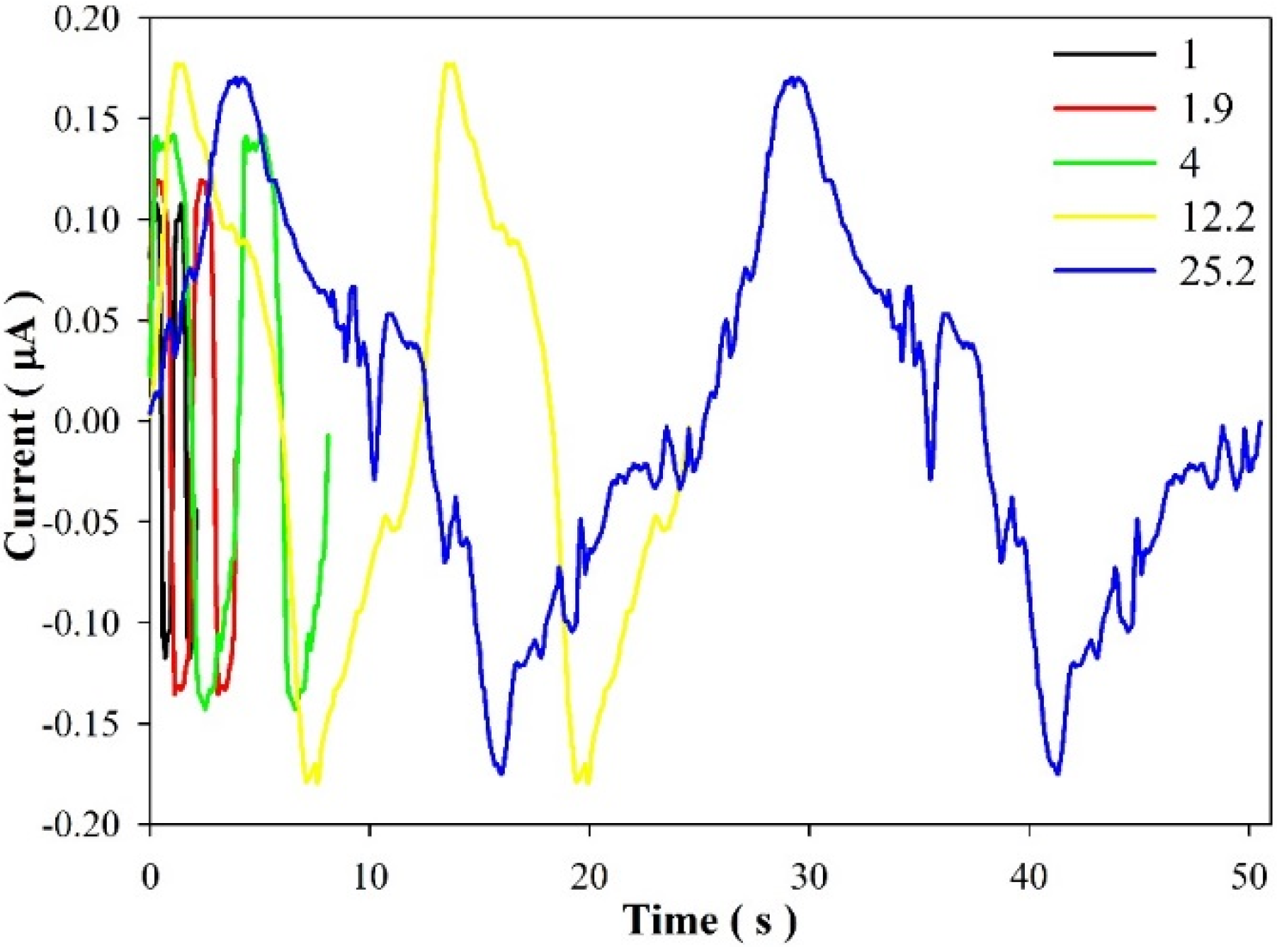
Moreover, the 50 μm thick PZT cell showed superior harvesting of the pyroelectric energy compared to the 200 μm thick PZT cell during a smaller period under 4 × 10⁻³ s. This could be attributed to the fact the thinner PZT cell possesses a lower thermal capacity for enhancing the temperature variation rate. The period band of the 50 μm thick PZT cell for efficiently harvesting the cyclic heating energy was narrower than that of the 200 μm thick PZT cell. The efficient period band of the 50 μm thick PZT cell was about 0.01 to 0.18 s, while that of the 200 μm thick PZT cell was about 0.06 to 0.8 s. The thicker PZT cell had a wider period band than the thinner PZT cell did. The efficient period band decreased about 77% when the thickness of the PZT cell decreased from 200 μm to 50 μm, about 75%. Therefore, in using the thinner PZT cell for harvesting the pyroelectric energy, it was not easy to focus on a narrow band of the efficient period. The pyroelectric energy harvesting with the thinner PZT cell needed to accurately use the period to achieve the best performance. Moreover, harvesting the pyroelectric energy transformed into the induced charge in the thinner PZT cell was greater than that in the thicker PZT cell during the optimal period. The optimal induced charge per period increased about 157% when the thickness of the PZT cell decreased about 75%. However, the optimal output voltage and stored energy per period decreased about 50% and 74%, respectively, when the thickness of the PZT cell decreased about 75%. This phenomenon could be attributed to the thinner pyroelectric cell possessing greater electrical capacitance (CP). Moreover, the electrical capacitance of the 50 μm thick pyroelectric cell was about four times greater than that of the 200 μm thick pyroelectric cell. Because the stored energy was proportional to the square of the output voltage, the stored energy experienced a larger decline than the output voltage. An experimental setup was used to verify and observe the work cycle to be able to affect the efficiency of the pyroelectric harvesters. The PZT cells were heated with the heat lamp, and naturally cooled with the rotating disk to obstruct the heat source. The temperature fluctuation was controlled on a range between 406 K and 403 K. Figure 9 shows the relationships between the current and time at five periods of 1 s, 1.9 s, 4 s, 12.2 s and 25.2 s for the commercial PZT pyroelectric cell with dimensions of 9 mm × 9 mm × 0.214 mm used. The response current was bumpier when the periods increased to 25.2 s due to the environmental temperature noise which was greater in the larger period.
Figure 9.
Relationships between the current and time at five periods of 1 s, 1.9 s, 4 s, 12.2 s and 25.2 s under the commercial PZT pyroelectric cell used.
Figure 9.
Relationships between the current and time at five periods of 1 s, 1.9 s, 4 s, 12.2 s and 25.2 s under the commercial PZT pyroelectric cell used.

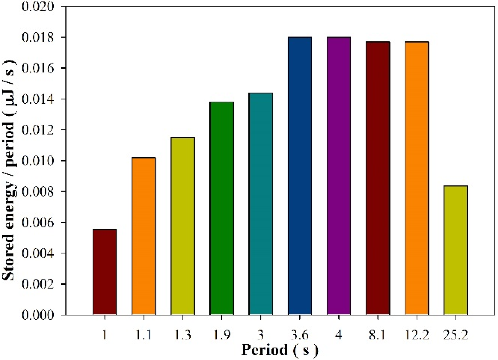
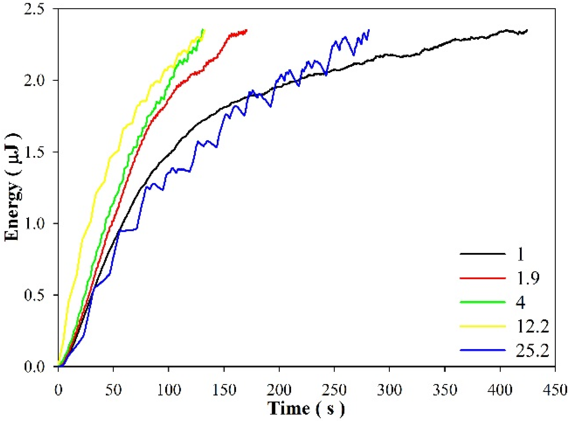
Figure 10 shows the relationships between the stored energy per period and various periods when the commercial PZT pyroelectric cell was used. The efficient period band of the commercial PZT pyroelectric cell was about 3.6 s to 12.2 s. Figure 11 shows the relationships between the stored energy in the 4.7 μF electrolytic capacitor and time at various periods.
Figure 10.
Relationships between the stored energy per period and various periods under the commercial PZT pyroelectric cell used.
Figure 10.
Relationships between the stored energy per period and various periods under the commercial PZT pyroelectric cell used.

Figure 11.
The stored energy over time at various periods during consecutive heating and cooling cycles.
Figure 11.
The stored energy over time at various periods during consecutive heating and cooling cycles.

Obviously, the period in the efficient period band revealed the best performance for harvesting thermal cyclic energy by pyroelectricity. Moreover, the stored energy in the capacitor increased according to expression (5). The smaller and the larger period could not efficiently harvest thermal cyclic energy. The pyroelectric element conversion of thermal cyclic energy into electricity was feeble in the smaller period due to the thermal capacity of pyroelectric elements. In other words, the pyroelectric element needed a thermal time constant (τT = H/GT, H: thermal capacity, GT: thermal conductance) to sufficiently harvest thermal energy with the pyroelectric material. Moreover, the pyroelectric element conversion of thermal cyclic energy into electricity was also weak in the larger period due to the lower temperature variation rate over the period. Although the temperature variation rate was larger for harvesting thermal cyclic energy in the initial step, the large temperature variation rate could not be maintained over the period, therefore the temperature variation rate decreased, the induced charge decreased, and then the output voltage decreased. These resulted in a decrease of the stored energy, although the stored energy would increase until the next period. Therefore, the curve of the stored energy over time revealed some ripples when a larger period was used to harvest thermal cyclic energy. The ripples indicated that the larger period was unsuitable for harvesting thermal cyclic energy. The periods of 4 s and 12.2 s presented the best performance when the commercial PZT pyroelectric cell with dimensions of 9 mm × 9 mm × 0.214 mm was used. Hence, a period in the suitable range was beneficial for using the pyroelectric harvesters. The estimation of the frequency or work cycle could be applied to the design of the aperture sizes and number of the rotating disk, and the angular velocities for controlling the heated and unheated periods of the pyroelectric cells.
4. Conclusions
Energy harvesting using a cyclic heating system can effectively transform waste heat energy into electricity by pyroelectricity. The cyclic heating system is developed for varying the temperature in the pyroelectric cells between the hot and cold regions. A disk with apertures for radiation heating and natural cooling is used as the cyclic heating system. The critical consideration in a periodic temperature profile for optimizing the pyroelectric harvesters is the frequency or work cycle. This factor is related to the properties and dimensions of the air layer, radiation power, and the material properties, dimensions and structure of the pyroelectric cells. This study proposes a convenient method for estimating the frequency or work cycle in pyroelectric cells via the cyclic heating system. It is obvious that the optimal period decreased when the thickness of the PZT cell was reduced. Moreover, the optimal induced charge per period increased about 157% when the thickness of the PZT cell decreased from 200 μm to 50 μm, about 75%; however, the optimal output voltage and stored energy per period decreased about 50% and 74%, respectively. This phenomenon could be attributed to the thinner pyroelectric cell possessing greater electrical capacitance. In addition, an experiment was used to verify the work cycle to be able to critically affect the efficiency of the PZT pyroelectric harvesters. The periods in the range between 3.6 s and 12.2 s were optimal for harvesting thermal cyclic energy by pyroelectricity when a commercial PZT pyroelectric cell with dimensions of 9 mm × 9 mm × 0.214 mm was used. The optimal frequency or work cycle can be applied to the design of the rotating disk for controlling the heated and unheated periods of the pyroelectric cells, further improving the energy storage.
Acknowledgments
The authors are thankful for the financial support from the National Science Council of Taiwan through Grant No. MOST 103-2221-E-150-038, and the experimental support from the Common Laboratory for Micro and Nano Science and Technology at the National Formosa University.
Author Contributions
Jia-Wai Jhang was involved in the data collection and experimental work under supervision of Chun-Ching Hsiao who carefully edited the paper, provided technical support and guidance, and directly contributed the results of this article.
Conflicts of Interest
The authors declare no conflict of interest.
References
- Cuadras, A.; Gasulla, M.; Ferrari, V. Thermal energy harvesting through pyroelectricity. Sens. Actuators A 2010, 158, 132–139. [Google Scholar] [CrossRef]
- Lee, F.Y.; Navid, A.; Pilon, L. Pyroelectric waste heat energy harvesting using heat conduction. Appl. Therm. Eng. 2012, 37, 30–37. [Google Scholar] [CrossRef]
- Nguyen, H.; Navid, A.; Pilon, L. Pyroelectric energy converter using co-polymer P(VDF-TrFE) and Olsen cycle for waste heat energy harvesting. Appl. Therm. Eng. 2010, 30, 2127–2137. [Google Scholar] [CrossRef]
- Sebald, G.; Lefeuvre, E.; Guyornar, D. Pyroelectric energy conversion: Optimization principles. IEEE Trans. Ultrason. Ferroelect. Freq. Control 2008, 55, 538–551. [Google Scholar] [CrossRef]
- Hsiao, C.C.; Ciou, J.C.; Siao, A.S.; Lee, C.Y. Temperature field analysis for PZT pyroelectric cells for thermal energy harvesting. Sensors 2011, 11, 10458–10473. [Google Scholar] [CrossRef] [PubMed]
- Hsiao, C.C.; Siao, A.S.; Ciou, J.C. Improvement of pyroelectric cells for thermal energy harvesting. Sensors 2012, 12, 534–548. [Google Scholar] [CrossRef] [PubMed]
- Hsiao, C.C.; Siao, A.S. Improving pyroelectric energy harvesting using a sandblast etching technique. Sensors 2013, 13, 12113–12131. [Google Scholar] [CrossRef] [PubMed]
- Olsen, R.B.; Bruno, D.A.; Briscoe, J.M. Pyroelectric conversion cycles. J. Appl. Phys. 1985, 58, 4709–4716. [Google Scholar] [CrossRef]
- Whatmore, R.W. Pyroelectric devices and materials. Rep. Progr. Phys. 1986, 49, 1335–1386. [Google Scholar] [CrossRef]
- Mane, P.; Xie, J.; Leang, K.K.; Mossi, K. Cyclic energy harvesting from pyroelectric materials. IEEE Trans. Ultrason. Ferroelectr. Freq. Control 2011, 58, 10–17. [Google Scholar] [CrossRef] [PubMed]
© 2015 by the authors; licensee MDPI, Basel, Switzerland. This article is an open access article distributed under the terms and conditions of the Creative Commons Attribution license (http://creativecommons.org/licenses/by/4.0/).
Share and Cite
MDPI and ACS Style
Hsiao, C.-C.; Jhang, J.-W. Pyroelectric Harvesters for Generating Cyclic Energy. Energies 2015, 8, 3489-3502. https://doi.org/10.3390/en8053489
AMA Style
Hsiao C-C, Jhang J-W. Pyroelectric Harvesters for Generating Cyclic Energy. Energies. 2015; 8(5):3489-3502. https://doi.org/10.3390/en8053489
Chicago/Turabian StyleHsiao, Chun-Ching, and Jia-Wai Jhang. 2015. "Pyroelectric Harvesters for Generating Cyclic Energy" Energies 8, no. 5: 3489-3502. https://doi.org/10.3390/en8053489