Article

Comparison of Output Current Ripple in Single and Dual Three-Phase Inverters for Electric Vehicle Motor Drives

1
Department of Engineering Sciences, Ångström Laboratory, Uppsala University, Lägerhyddsvägen 1, Box 534, S-751 21 Uppsala, Sweden
2
Department of Electrical, Electronic, and Information Engineering, University of Bologna, Viale Risorgimento 2, 40136 Bologna, Italy
*
Author to whom correspondence should be addressed.
Energies 2015, 8(5), 3832-3848; https://doi.org/10.3390/en8053832
Submission received: 31 March 2015 / Accepted: 27 April 2015 / Published: 30 April 2015
(This article belongs to the Collection Electric and Hybrid Vehicles Collection)

Abstract

:
The standard solution for the traction system in battery powered electric vehicles (EVs) is a two-level (2L) inverter feeding a three-phase motor. A simple and effective way to achieve a three-level (3L) inverter in battery-supplied electric vehicles consists of using two standard three-phase 2L inverters with the open-end winding connection of standard three-phase ac motors. The 3L inverter solution can be usefully adopted in EVs since it combines several benefits such as current ripple reduction, increment of phase motor voltage with limited voltage ratings of the two battery banks, improvement in system reliability, etc. The reduction in current ripple amplitude is particularly relevant since it is a source of electromagnetic interference and audio noise from the inverter-motor power connection cables and from the motor itself. By increasing the inverter switching frequency the ripple amplitude is reduced, but the drive efficiency decreases due to the proportionally increased switching losses. In this paper the peak-to-peak ripple amplitude of the dual-2L inverter is evaluated and compared with the corresponding ripple of the single-2L inverter, considering the same voltage and power motor ratings. The ripple analysis is carried out as a function of the modulation index to cover the whole modulation range of the inverter, and the theoretical results are verified with experimental tests carried out by an inverter-motor drive prototype.

Graphical Abstract

1. Introduction

The multilevel (ML) inverter technology has become more and more popular and widely recognized in last decades as a viable solution to overcome the voltage limits of power switching converters. Multilevel converters are able to generate output voltage waveforms consisting of a large number of steps. In this way higher voltages can be synthesized using voltage sources with lower levels. As a result, they offer increased power ratings, improved output voltage waveforms, and reduced electromagnetic interference emission. These features have made multilevel converters suitable for both medium-voltage high-power motor drives and low-voltage high-efficiency conversion systems. Several multilevel inverter topologies have been introduced in the last fifteen years, the most important of them being the diode-clamped, the capacitor-clamped, and the cascaded converter [1]. Nowadays, many multilevel applications can be found in low voltage systems, in the place of standard three-phase inverters, Figure 1a, with the aim of reducing the output voltage distortion, the current ripple, and the cost in general [2]. Among the cascaded converters, the dual two-level (2L) inverter configuration has received large attention due to the simplicity of the power stage. It is based on two standard 2L three-phase voltage source inverters supplied by two separate dc sources. The motor load is connected in the open-end winding configuration [3,4,5,6,7,8], as shown in Figure 1b.
In the case of battery powered electric vehicles (EVs), the standard solution for the traction system is given by a 2L inverter feeding a three-phase motor, as shown in Figure 1a. The inverter is supplied by a bank of ion-lithium batteries. The battery pack voltage is in the range 300–400 V for a sedan, and about 100 V for a lightweight city car. Referring to this last application, nowadays, the practical feasibility of an ac drive with a power rating larger than 20 kW is limited. It is mainly due to the high cost of the semiconductor power switches and layout complexity of the power stage of the inverter required by the resulting high current rating.
The solution of ML inverters can be usefully adopted in EVs since it combines current ripple reduction with the possibility to adopt battery banks with lower voltages. Among different ML inverter topologies, the dual-2L inverter is particularly suitable and effective for EVs, being equivalent to a 3L inverter but with a traditional, cheap, and reliable three-phase inverter structure [3,4,5,6,7,8]. In this case, the motor is supplied from both the open-winding ends by two standard 2L inverters, as shown in Figure 1b. The two separate dc sources can be easily obtained on board of an EV by splitting the batteries into two separate banks. The use of this solution also improves system reliability since in case of the fault in one inverter-battery bank, the drive can be operated using the other one as a standard three-phase 2L inverter. In this recovery mode, the operation of the motor drive at the rated current (i.e., rated torque) up to the half of the rated voltage (i.e., half of the rated speed) is possible [5].
Figure 1. Basic schemes of three-phase motor traction drives. (a) Single-2L inverter with double dc voltage; (b) dual-2L inverter (3L) with two single dc voltage.
Energies 08 03832 g001
From the point of view of the inverter, the current ripple can be simply reduced by increasing the switching frequency, but this leads to increased switching losses, lowering the drive efficiency. Reducing the inverter-motor current ripple in EV drives is an important issue since the ripple amplitude is related to the acoustic noise emitted from the motor, and to the electromagnetic (EM) emission which interferes with the on-board electronic devices and particularly with the audio quality of the infotainment system [9].
Although the dual inverter structure has been intensively examined in the last decades [3,4,5,6,7,8,10,11,12], no studies are available concerning the amplitude of current ripple, except for [6], but there the RMS value was of interest. In particular, the analysis of the output current ripple amplitude in three-phase 2L inverters has been recently introduced in [13,14,15]. The extension to 2L multiphase inverters is given in [16,17,18], and compared in [19], whereas the extension to 3L three-phase inverters is given in [20] and [21]. In general, the knowledge of peak-to-peak current ripple amplitude in inverter motor drives allows one to optimize the switching frequency (and the associated losses), handle and minimize the acoustic noise, and mitigate the electromagnetic interference [17,22].
In this paper the analysis of the inverter-motor current ripple amplitude is applied to the dual-2L inverter drive structure of Figure 1b, on the basis of developments given in [20,21], comparing the results with the traditional single-2L inverter motor drive in Figure 1a, being the most adopted configuration in EV drives. Reference is made to centered and symmetrical PWM switching patterns, able to minimize the current ripple RMS, and easy to implement with both space vector (SV) and carried-based (CB) modulation schemes [23,24,25].

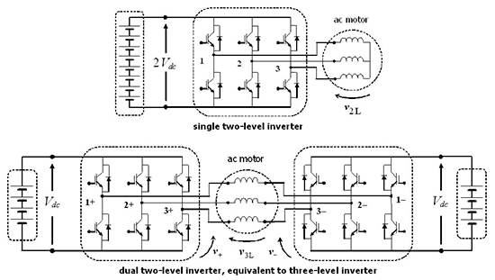
2. Space Vector Analysis of Single and Dual Inverters

The use of space vectors in the analysis of three-phase inverters is introduced here since it leads to a better understanding and more simple calculation of voltage levels and corresponding application times.
The single-2L inverter is supposed to be supplied by 2Vdc, to obtain the same output voltage capability of the dual inverter, supplied by Vdc at each dc side. By denoting the switching states of the k-th phase as Sk = [0, 1], Figure 1a, the output voltage vector v2L of the 2L inverter can be expressed as:
v 2 L = 4 3 V d c [ S 1 + S 2 α + S 3 α 2 ]
being α = exp(j2π/3). With reference to the dual-2L inverter, Figure 1b, by denoting as Sk+ and Sk the switching states of the k-th phase of left- and right-side inverters, the output voltage vector v3L can be expressed as [5]:
v 3 L = v + v
{ v + = 2 3 V d c ( S 1 + + S 2 + α + S 3 + α 2 ) v = 2 3 V d c ( S 1 + S 2 α + S 3 α 2 )
v 3 L = 2 3 V d c [ S ¯ 1 + S ¯ 2 α + S ¯ 3 α 2 ]
being Sk = Sk+Sk = [−1, 0, 1] the equivalent 3L switching states of the dual-2L inverter, denoted in the following as {− 0 +}. From this point of view, dual 2L inverter is corresponding to the 3L inverter.
Figure 2 shows the output voltage space vectors corresponding to all possible switch configurations in 2L and dual-2L (3L) inverters. For both inverters the space vector diagram appears to be a hexagon divided into six main triangles, sectors I–VI. Note that by supplying the 2L inverter by 2Vdc, the resulting hexagon size corresponds to the size of the outer hexagon generated by the dual-2L (3L) inverter, i.e., the two configurations (a) and (b) in Figure 2 offer the same output voltage capabilities (blue dashed circles represent the modulation limit for sinusoidal balanced output voltages).
Figure 2. Output voltage space vector diagrams. (a) Single-2L inverter supplied by 2Vdc; (b) dual-2L inverter (3L) supplied by Vdc at each side.
Energies 08 03832 g002

3. Inverter Modulation

3.1. Space Vector Modulation

The nearest three vectors (NTV) algorithm is adopted to approximate the reference output voltage vector for 2L and 3L inverters in most of SV-PWM schemes. Among these three vectors, one corresponding to redundant switching states is used as base vector in the modulation pattern, and it is usually called pivot vector [26].
In 2L inverters the only pivot vector is the null vector, corresponding to switch states {0 0 0} and {1 1 1} (Figure 2a). In addition to the redundant states corresponding to the null vector, i.e., {+ + +}, {0 0 0}, and {− − −}, in 3L inverters there are six further redundant states corresponding to the six vectors of magnitude 2/3 Vdc (enlarged red dots in Figure 2b). Only these six vectors are used as pivot (base) vectors in 3L inverter [26].
In the case of continuous modulation, the switching sequence starts from one pivot state, goes to the other switching states, and comes back to the first for both 2L and 3L inverters. Beginning and ending states of this traverse correspond to the same pivot (base) vector, that is the null vector in case of 2L inverters, and pivot vector in case of 3L inverters. The working domain of each pivot vector is the sub-hexagon centered on it. In the case of 3L inverter, due to the overlaps between sub-hexagons, the working domain of each pivot vector is restricted to a diamond-shaped region (pivot sector, limited by red lines in Figure 2b).
For sinusoidal balanced output voltages, the reference output voltage vector is v* = V*exp(jϑ), being V* = mVdc, ϑ = ωt. Note that the limits of linear modulation are 0 ≤ m ≤ 2/√3, for both 2L and dual-2L (3L) inverter, being m the modulation index. The analysis can be restricted to the first quadrant in the considered case of quarter-wave symmetric modulation.
Application times tk of NTV are defined by duty-cycles δ1, δ2, and δ0 i.e., δp, for 2L i.e., 3L inverters, and switching period Ts, being δk = tk/(Ts/2). Duty-cycles for the 1st quadrant of 2L and 3L inverters are given in [14,20,21]. Normalized reference voltages uα and uβ are used for duty-cycles calculation and are given as:
u α = v α V d c = m cos ϑ , u β = v β V d c = m sin ϑ
being α and β the indexes for real and imaginary components of v*. The calculation of duty-cycles can be easily extended to the other sectors for 2L and dual-2L (3L) inverters [27,28].

3.2. Implementation of Centered (Optimized) Modulation in Carrier-Based PWM

The centered space vector PWM is considered to be optimal modulation from many points of view. In centered space vector PWM application time of pivot vector (δ0 or δp for 2L or 3L inverters) is shared into equal parts for the two redundant pivot states. In this way nearly-optimal modulation is obtained, being able to minimize the RMS of current ripple [23,24]. An equivalent switching pattern to the centered SV PWM can be achieved also in CB-PWM, by injecting a proper common-mode signal to the reference voltage waveforms. In this way, the resulting modulating signals are able to equally share the application times of redundant states, as in SV PWM, and the linear modulation range is maximized as well.
In the case of 2L inverters a simple min/max injection can be used for centering in CB-PWM [27], as shown in Figure 3a. Unlike 2L inverters, in case of 3L inverters a more complex common-mode signal has to be added to reference voltages [23,24], as shown in Figure 3b. A simplified procedure to obtain the centered optimized modulating signals has been recently introduced in [25] for the 3L case, also suitable for the dual-2L inverter.
Figure 3. Example of modified modulating signals (normalized by Vdc) for optimized centered carrier-based PWM (m = 0.8). (a) Single-2L inverter supplied by 2Vdc; (b) dual-2L inverter (3L) supplied by Vdc at each side.
Energies 08 03832 g003
The ripple analysis is developed in this paper for centered space vector modulation, implemented by CB-PWM, being one of the most popular 2L and ML modulation strategies. In particular, CB-PWM offers inherent simplicity, flexibility, reduced computational time, and easy implementation on industrial DSPs, without the need of FPGA or any other additional hardware.

4. Current Ripple Evaluation

4.1. Current Ripple Definitions

Due to the symmetry among the three phases in the considered case of sinusoidal balanced currents, only the 1st phase is examined in the following analysis. The current ripple definition introduced in [14,20,21] is briefly recalled here. The alternating voltage component can be written by averaging over the switching period as:
v ˜ ( t ) = v ( t ) v ¯ ( T s )
which allows defining the instantaneous current ripple as:
i ˜ ( t ) = Δ i ( t ) t T s Δ i 1 L 0 t v ˜ ( t ) d t
Peak-to-peak current ripple amplitude is practically the envelope of Equation (7), and it can be calculated as:
i ˜ p p = max { i ˜ ( t ) } 0 T s min { i ˜ ( t ) } 0 T s
In terms of space vectors, the variables of the 1st phase are given by the projection of the corresponding space vectors on the real axis. In particular, if the reference voltage is within the modulation limits, i.e., the reference space vector v* lies within the outer hexagon, the average of the output voltage in the switching period Ts is given by:
v ¯ ( T s ) =     v * = Re { v * } = V * cos ϑ = V d c m cos ϑ
The instantaneous output voltage of the 1st phase can be expressed by switching states defined in Equations (1) and (4), leading to:
v ( t ) = 2 V d c [ S 1 1 3 ( S 1 + S 2 + S 3 ) ]   for   2 L   inverter ,
v ( t ) = V d c [ S ¯ 1 1 3 ( S ¯ 1 + S ¯ 2 + S ¯ 3 ) ]   for   dual - 2 L   ( 3 L )   inverter .
The alternating voltage component for 2L and 3L inverters can be determined by introducing Equations (10), (11), and (9) in Equation (6):
v ˜ ( t ) = 2 V d c [ S 1 1 3 ( S 1 + S 2 + S 3 ) ] m V d c cos ϑ   for   2 L   inverter ,
v ˜ ( t ) = V d c [ S ¯ 1 1 3 ( S ¯ 1 + S ¯ 2 + S ¯ 3 ) ] m V d c cos ϑ   for   3 L   inverter .
In order to evaluate the current ripple for both 2L and 3L inverters, only the gray colored regions in Figure 2 can be considered, keeping in mind the quarter-wave symmetry. In particular, three cases are identified within the 1st quadrant in 2L case (Sector I and half of the Sector II), and corresponding quadrant in dual-2L (3L) case, i.e., triangle I-3b and part of the triangle II-3a (within the domain of the pivot vector vp1). The same quadrant can be noticed within the domain of the pivot vector vp6, and for the ripple calculation can be used either of the two. The results are readily extended to the whole pivot sectors (in the case of dual-2L inverter) and then whole hexagon by exploiting the quarter-wave symmetry.

4.2. Current Ripple Evaluation in Single-2L Inverter

The ripple evaluation in the case of 2L inverter, presented also in [14], is summarized here. Considering 2L inverter, two different cases can be distinguished in sector I: 0 ≤ mcosϑ ≤ 2/3 and mcosϑ ≥ 2/3, and one case for the half of the sector II, when 60° < ϑ < 90°.
Considering sub-case 0 ≤ mcosϑ ≤ 2/3, i ˜ p p can be evaluated by Equations (7), (8) and (12), considering either switch configuration {1 1 1} or {0 0 0}, and the corresponding application time t0/2, i.e., duty-cycle δ0/2. Normalizing by Equation (5) gives:
i ˜ p p = 2 V d c T s 2 L { m cos ϑ   δ 0 } = V d c T s L { u α δ 0 }
Peak-to-peak current ripple can also be expressed as:
i ˜ p p = V d c T s 2 L r ( m , ϑ )
being r(m, ϑ) the normalized peak-to-peak current ripple amplitude. Introducing in Equation (14) the expression of δ0, given in [14,21], the normalized current ripple defined in Equation (15) becomes:
r ( m , ϑ ) = 2 u α [ 1 3 2 ( u α + 1 3 u β ) ]
The second sub-case is when 2/3 ≤ mcosϑ ≤ 2/√3. In this case i ˜ p p can be evaluated considering both the switch configurations {1 1 1} and {1 1 0} with the corresponding duty-cycles δ0/2 and δ2. Normalizing by Equation (5) gives:
i ˜ p p = V d c T s L { u α δ 0 + 2 ( u α 1 3 ) δ 2 }
Introducing in Equation (17) the expression of δ0 and δ2, the normalized current ripple becomes:
r ( m , ϑ ) = 2 u α [ 1 3 2 ( u α + 1 3 u β ) ] + 4 3 u β ( u α 1 3 )
The only sub-case of the half of sector II is when 60° < ϑ < 90°. In this case, i ˜ p p can be evaluated considering both the switch configurations {0 0 0} and {0 1 0} with the corresponding duty-cycles δ0/2 and δ2. Normalizing by Equation (5) gives:
i ˜ p p = V d c T s L { u α δ 0 + 2 ( u α + 1 3 ) δ 2 }
Substituting in Equation (17) the expression of δ0 and δ2, the normalized current ripple becomes:
r ( m , ϑ ) = 2 u α [ 1 3 u β ] + 6 ( 1 3 u β u α ) ( u α + 1 3 )
The analysis can be easily extended to all the other sectors of the 2L hexagon by exploiting the quarter-wave symmetry [14].

4.3. Current Ripple Evaluation in Dual-2L Inverter (3L)

The ripple evaluation in the case of 3L inverter, presented also in [20,21], is summarized here. Considering dual-2L (3L) inverter and the corresponding quadrant within the domain of the pivot vector vp1 (gray colored area in Figure 2), two different cases can be distinguished in triangle I-3b: 1/3 ≤ mcosϑ ≤ 2/3 and mcosϑ ≥ 2/3, and one single case for the half of the triangle II-3a, when mcosϑ ≥ 1/3.
The first considered sub-case is the part of triangle I-3b when 1/3 ≤ mcosϑ ≤ 2/3. In this case, i ˜ p p can be evaluated by Equations (7), (8), and (13), considering the switch configuration {+ + 0} or {0 0 −} with the corresponding duty-cycle δp/2, leading to:
i ˜ p p = V d c T s 2 L { ( m cos ϑ 1 3 ) δ p } = V d c T s 2 L { ( u α 1 3 ) δ p }
After introducing the expression for δp given in [20] for 3L inverter and normalization, the current ripple becomes:
r ( m , ϑ ) = ( u α 1 3 ) [ 2 3 2 ( u α + 1 3 u β ) ]
The second considered sub-case is representing the part of triangle I-3b when mcosϑ ≥ 2/3. In this case i ˜ p p can be evaluated considering switch configurations {+ + 0} and {+ + −} and the corresponding duty-cycles δp/2 and δ2, leading to:
i ˜ p p = V d c T s 2 L { ( m cos ϑ 1 3 ) δ p + 2 ( m cos ϑ 2 3 ) δ 2 }
After introducing the expressions for δp and δ2 given in [20] for 3L inverter and normalization, current ripple becomes:
r ( m , ϑ ) = ( u α 1 3 ) [ 2 3 2 ( u α + 1 3 u β ) ] + 2 ( u α 2 3 ) ( 3 u β 1 ) .
The only considered sub-case in the half of the triangle II-3a is when mcosϑ ≥ 1/3. In this case i ˜ p p can be evaluated considering the switch configurations {+ + 0} and {0 + −} and the corresponding duty-cycles δp/2 and δ2, leading to:
i ˜ p p = V d c T s 2 L { ( m cos ϑ 1 3 ) δ p + 2 m cos ϑ δ 2 }
After introducing the expressions of δp and δ2 given in [20] for 3L inverter and normalization, current ripple becomes:
r ( m , ϑ ) = ( u α 1 3 ) ( 2 3 u β ) + 3 u α ( 1 3 u β u α )
The analysis can be extended to all the other sectors of the 3L hexagon by exploiting the quarter-wave symmetry [20,21].

5. Results

5.1. Theoretical Results

Theoretical results relevant for the current ripple in single-2L and dual-2L (3L) inverters are given here. Analysis and comparison of the output current ripple for the two inverters are made with reference to the schemes presented in Figure 1, and based on the analytical developments presented in the previous section.
In Figure 4 the normalized function r(m, ϑ) defined by Equation (15) is shown, considering various modulation indexes (m = 1/3, 2/3, and 1), in case of 2L and dual-2L inverters. As expected, the current ripple in dual-2L inverter is generally lower than the ripple of single-2L inverter, valid for the whole phase angle range. In the same figure, the maximum normalized current ripple (rmax) is emphasized with dots. From the figure can be noted that rmax in case of dual-2L inverter has a reduced variability with m, almost close to the value 0.2 (dashed line), whereas rmax in the case of 2L inverter is increasing almost proportionally with m [14]. This is due to the lower distance between the reference vector v* and the available voltage vectors in the case of dual-2L inverter, as consequence of applying the NTV modulation.
Figure 4. Normalized peak-to-peak current ripple amplitude r(m, ϑ) for single- and dual-2L inverters in the range ϑ = [0, 90°] for different modulation indexes.
Energies 08 03832 g004
In Figure 5 the average of normalized current ripple, ravg, is shown as a function of the modulation index. The goal was to summarize the current ripple amplitude in the whole fundamental period for the two inverters, considering the same output voltage capabilities. It can be noticed that single-2L inverter has almost the double of the average normalized ripple compared to dual-2L inverter, except for low modulation indexes, i.e., less than 0.4.
Figure 5. Average normalized current ripple vs. modulation index for single-2L and dual-2L (3L) inverters.
Energies 08 03832 g005
Figure 5 also shows that ravg has a reduced excursion range in the case of dual-2L inverter, ranging between 0.075 and 0.15 for m = [0.1, 1.15], whereas it is a monotonic increasing function of m in the case of 2L inverter, ranging between 0.075 and 0.31 (i.e., almost the double) [14]. Note that the average current ripple amplitude can be related to the acoustic noise emission from the motor in case of switching frequencies within the audible frequencies.

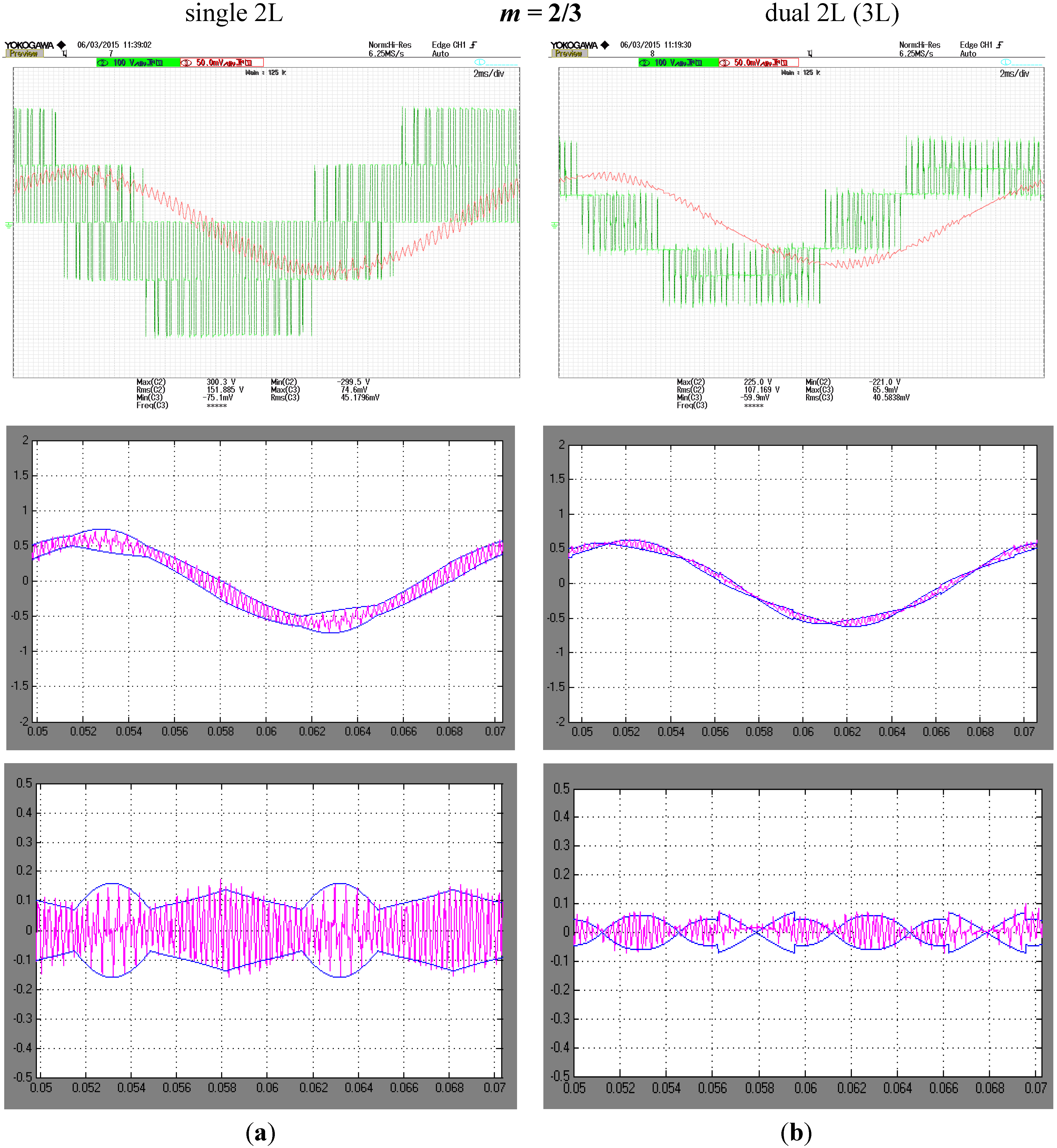
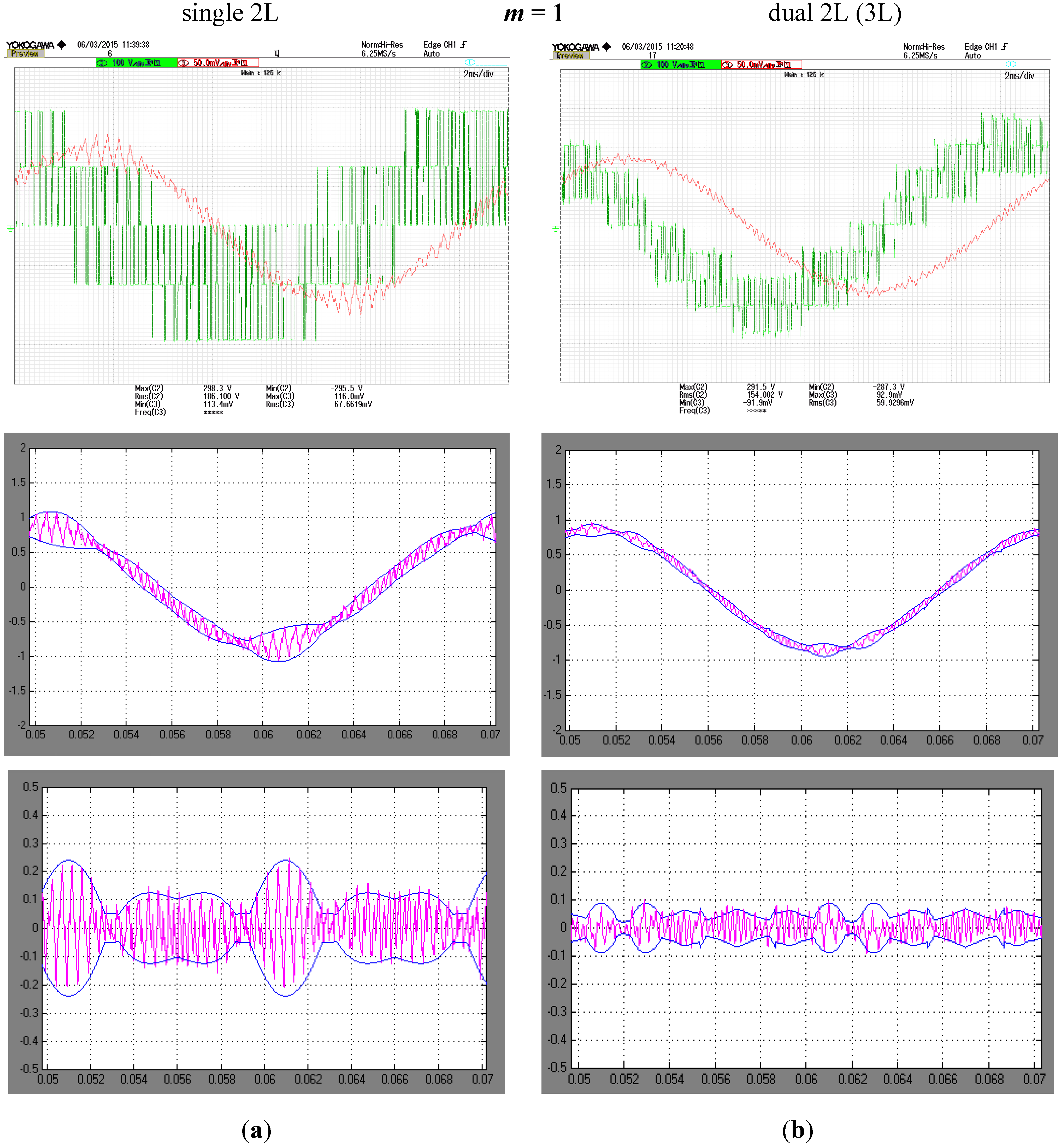
5.2. Experimental Results

Experimental results are carried out to verify the peak-to-peak current ripple amplitude calculated by the proposed analytical developments, considering both single- and dual-2L inverters. The experimental setup including the custom-made inverters and the Arduino Due microcontroller board, based on the 84 MHz Atmel SAM3X8E ARM Cortex-M3 CPU, is presented in Figure 6.
Figure 6. Experimental setup. (a) Single-2L inverter feeding the star-connected three-phase induction motor; (b) dual-2L inverter feeding the same motor in the open-end windings configuration; (c) microcontroller board with optic link fibers (up and bottom sides).
Energies 08 03832 g006
The three-phase Mitsubishi PS22A76 intelligent power modules (1200 V, 25 A) have been used for the implementation of single- and dual-2L inverters. The experiments have been carried out by a three-phase induction motor load, in star and open winding configuration, considering single- and dual-2L inverters, respectively. The main rated motor parameters are: Pn = 0.55 kW, Vn = 380 V (star connected), fn = 50 Hz, ωn = 1400 rpm, two pole pairs. According to the model of induction motor for higher order harmonics, the total equivalent leakage inductance L ≈ 60 mH has been experimentally determined and considered for the ripple evaluation.
The single-2L inverter was supplied with 2Vdc = 420 V, while each inverter in the dual-2L configuration was supplied with Vdc = 210 V. Switching frequency was set to 2.1 kHz and fundamental frequency was kept at 50 Hz for easier comparison with analytical developments. A relatively low switching frequency was chosen in order to keep the current ripple well visible within one fundamental period. The nearly-optimal centered carrier-based PWM is implemented leading to equally share the application times of pivot vectors, as described in Section 3.2.
A Yokogawa DLM2024 oscilloscope with a PICO TA057 differential voltage probe and LEM PR30 current probe were used for measurements, and the built-in noise filter (cut-off frequency fc = 16 kHz) was applied to the current signal. Instantaneous current ripple is evaluated by post processing the experimental data with numerical high-pass filter in Matlab (cut-off frequency 0.5 kHz, essentially to remove the fundamental current component).
As in the previous sections, the 1st phase is selected for further analysis and different values of m are investigated. In Figure 7, Figure 8 and Figure 9 are shown the experimental results for three different modulation indexes, m = 1/3, 2/3, and 1, respectively. Left side diagrams correspond to single-2L inverter, right side diagrams correspond to dual-2L inverter. The same y-axis range has been selected for easier comparison.
Figure 7. Experimental results: details of the output voltage and current waveforms from the oscilloscope, instantaneous output current with calculated peak-to-peak amplitude envelopes, and detail of current ripple with envelopes for m = 1/3: (a) single-2L inverter; (b) dual-2L (3L) inverter.
Energies 08 03832 g007
Figure 8. Experimental results: details of the output voltage and current waveforms from the oscilloscope, instantaneous output current with calculated peak-to-peak amplitude envelopes, and detail of current ripple with envelopes for m = 2/3: (a) single-2L inverter; (b) dual-2L (3L) inverter.
Energies 08 03832 g008
Figure 9. Experimental results: details of the output voltage and current waveforms from the oscilloscope, instantaneous output current with calculated peak-to-peak amplitude envelopes, and detail of current ripple with envelopes for m = 1: (a) single-2L inverter; (b) dual-2L (3L) inverter.
Energies 08 03832 g009
In the upper diagrams are shown the oscilloscope screenshots with voltage and current waveforms for both single- and dual-2L inverter configurations (voltage across the 1st phase winding and corresponding phase motor current). It can easily be noted that voltages have the same maximum level (4/3Vdc = 280 V) in the two configurations, whereas the current ripple is higher in the case of the single-2L inverter, as expected.
For all figures, the middle and lower diagrams are obtained by post processing in Matlab the experimental current data shown in the upper diagrams. In the middle diagrams are shown the instantaneous phase currents (purple traces) together with the calculated peak-to-peak current ripple absolute envelopes (blue traces). In the lower diagrams are shown the current ripples evaluated by high-pass filtering the instantaneous currents (purple traces) together with the peak-to-peak current ripple envelopes (blue traces).
It can be noted that the experimental results are in very good agreement with the calculated current ripple envelopes, for all the considered cases, proving the effectiveness of the proposed analytical developments for practical and realistic applications. In general, the amplitude of the current ripple is well recognizable and the ripple reduction in the case of the dual-2L inverter compared to the single-2L inverter is evident, according to the summarizing diagram shown in Figure 5.

6. Conclusions

The output current ripple in dual-2L inverter-motor drive configuration has been analyzed in this paper, being a viable solution from many point of view for EVs compared to its single-2L inverter counterpart. Specifically, the dual-2L inverter, acting as 3L inverter, offers a significant ripple reduction, with other benefits such as reduced acoustic noise emitted from the motor, and mitigated electromagnetic emission. Moreover, by using the dual-2L inverter instead of single-2L inverter is exploited the possibility to split the battery bank into two equal isolated parts, with the additional benefit of halved dc voltages and improved reliability of the whole vehicle drive.
In particular, the peak-to-peak ripple amplitude has been compared considering the same voltage and power motor ratings, i.e., the same maximum output voltage for single- and dual-2L inverters, and the same switching frequency. The optimal centered CB-PWM is considered in both cases for the ripple evaluation, being one of the most popular modulations, easy to be implemented with both industrial DSPs and commercial microcontroller boards. Different diagrams of the normalized peak-to-peak ripple for single- and dual-2L inverters were presented and compared. It should be noted that the current ripple amplitude is not affected by the fundamental frequency, i.e., the motor speed, leaving as the only variable of interest the modulation index for a given switching frequency.
As expected, the current ripple of dual-2L inverter is lower in whole modulation range, with a reduced excursion, whereas the current ripple is an increasing function of m in the case of the single-2L inverter, with a resulting excursion that is almost the double. This makes the dual inverter configuration a viable solution for EV motor drives from the point of view of acoustic noise and vibration reduction, and mitigation of conducted and radiated electromagnetic interferences.
The analytical developments have been verified with experimental tests carried out by an inverter-motor drive prototype with both the single- and the dual-2L inverter configurations. The experimental results show a very good matching with the analytical developments for different modulation indexes covering the whole modulation range.

Author Contributions

All the contributions in this paper are equally shared among the authors.

Conflicts of Interest

The authors declare no conflict of interest.

References

  1. Rodríguez, J.; Lai, J.S.; Peng, F.Z. Multilevel inverters: A survey of topologies, controls, and applications. IEEE Trans. Ind. Electron. 2002, 49, 724–738. [Google Scholar] [CrossRef]
  2. Franquelo, L.G.; Rodriguez, J.; Leon, J.I.; Kouro, S.; Portillo, R.; Prats, M.M. The age of multilevel converters arrives. IEEE Trans. Ind. Electron. Mag. 2008, 2, 28–39. [Google Scholar] [CrossRef]
  3. Kawabata, Y.; Nasu, M.; Nomoto, T.; Ejiogu, E.C.; Kawabata, T. High-efficiency and low acoustic noise drive system using open-winding AC motor and two space-vector-modulated inverters. IEEE Trans. Ind. Electron. 2002, 49, 783–789. [Google Scholar] [CrossRef]
  4. Kim, J.; Jung, J.; Nam, K. Dual-inverter control strategy for high-speed operation of EV induction motors. IEEE Trans. Ind. Electron. 2004, 51, 312–320. [Google Scholar] [CrossRef]
  5. Rossi, C.; Casadei, D.; Grandi, G.; Lega, A. Multilevel operation and input power balancing for a dual two-level inverter with insulated DC sources. IEEE Trans. Ind. Appl. 2008, 44, 1815–1824. [Google Scholar] [CrossRef]
  6. Srinivas, S.; Sekhar, K.R. Theoretical and experimental analysis for current in a dual-inverter-fed open-end winding induction motor drive with reduced switching PWM. IEEE Trans. Ind. Electron. 2013, 60, 4318–4328. [Google Scholar] [CrossRef]
  7. Sekhar, K.R.; Srinivas, S. Discontinuous decoupled PWMs for reduced current ripple in a dual two-level inverter fed open-end winding induction motor drive. IEEE Trans. Power Electron. 2013, 28, 2493–2502. [Google Scholar] [CrossRef]
  8. Hong, J.; Lee, H.; Nam, K. Charging method for the secondary battery in dual inverter drive systems for electric vehicles. IEEE Trans. Power Electron. 2015, 30, 909–921. [Google Scholar] [CrossRef]
  9. Mutoh, N.; Kanesaki, M. A suitable method for ecovehicles to control surge voltage at motor terminals connected to PWM inverters and to control induced EMI noise. IEEE Trans. Veh. Technol. 2008, 57, 2089–2098. [Google Scholar] [CrossRef]
  10. Kanchan, R.; Tekwani, P.; Gopakumar, K. Three-level inverter scheme with common mode voltage elimination and dc link capacitor voltage balancing for an open-end winding induction motor drive. IEEE Trans. Power Electron. 2006, 21, 1676–1683. [Google Scholar] [CrossRef]
  11. Grandi, G.; Tani, A.; Sanjeevikumar, P.; Ostojic, D. Multi-phase multi-level AC motor drive based on four three-phase two-level inverters. In Proceedings of the 20th Symposium on Power Electronics, Electrical Drives and Advanced Electrical Motors (SPEEDAM), Pisa, Italy, 14–16 June 2010; pp. 1768–1775.
  12. Boller, T.; Holtz, J.; Rathore, A.K. Optimal pulsewidth modulation of a dual three-level inverter system operated from a single DC link. IEEE Trans. Ind. Appl. 2012, 48, 1610–1615. [Google Scholar] [CrossRef]
  13. Ruderman, A. Understanding PWM current ripple in star-connected AC motor drive. IEEE Power Electron. Soc. Newsl. 2009, 21, 14–17. [Google Scholar]
  14. Grandi, G.; Loncarski, J. Evaluation of current ripple amplitude in three-phase PWM voltage source inverters. In Proceedings of the 8th IEEE International Conference-Workshop on Compatibility and Power Electronics (CPE), Ljubljana, Slovenia, 5–7 June 2013; pp. 156–161.
  15. Jiang, D.; Wang, F. Current-ripple prediction for three-phase PWM converters. IEEE Trans. Ind. Appl. 2014, 50, 531–538. [Google Scholar] [CrossRef]
  16. Grandi, G.; Loncarski, J. Evaluation of current ripple amplitude in five-phase PWM voltage source inverters. In Proceedings of the IEEE Conference on ICT, Power Engineering, and Signal Processing (EUROCON), Zagreb, Croatia, 1–4 July 2013; pp. 1073–1080.
  17. Jiang, D.; Wang, F. A general current ripple prediction method for the multiphase voltage source converter. IEEE Trans. Power Electron. 2014, 29, 2643–2648. [Google Scholar] [CrossRef]
  18. Grandi, G.; Loncarski, J. Analysis of peak-to-peak current ripple amplitude in seven-phase PWM voltage source inverters. Energies 2013, 6, 4429–4447. [Google Scholar] [CrossRef]
  19. Grandi, G.; Loncarski, J.; Rossi, C. Comparison of peak-to-peak current ripple amplitude in multiphase PWM voltage source inverters. In Proceedings of the 15th IEEE Conference on Power Electronics and Applications (EPE'13 ECCE Europe), Lille, France, 3–5 September 2013.
  20. Grandi, G.; Loncarski, J.; Dordevic, O. Analytical evaluation of output current ripple amplitude in three-phase three-level inverters. IET Power Electron. 2014, 7, 2258–2268. [Google Scholar] [CrossRef]
  21. Grandi, G.; Loncarski, J.; Dordevic, O. Analysis and comparison of peak-to-peak current ripple in two-level and multilevel PWM inverters. IEEE Trans. Ind. Electron. 2014. [Google Scholar] [CrossRef]
  22. Schulz, S.E.; Kowalewski, D.L. Implementation of variable-delay random PWM for automotive applications. IEEE Trans. Veh. Technol. 2007, 56, 1427–1433. [Google Scholar] [CrossRef]
  23. Wang, F. Sine-triangle versus space-vector modulation for three-level PWM voltage-source inverters. IEEE Trans. Ind. Appl. 2002, 38, 500–506. [Google Scholar] [CrossRef]
  24. McGrath, B.P.; Holmes, D.G.; Lipo, T.A. Optimized space vector switching sequences for multilevel inverters. IEEE Trans. Power Electron. 2003, 18, 1293–1301. [Google Scholar] [CrossRef]
  25. Grandi, G.; Loncarski, J. Simplified implementation of optimised carrier-based PWM in three-level inverters. IET Electron. Lett. 2014, 50, 631–633. [Google Scholar] [CrossRef]
  26. Seo, J.H.; Choi, C.H.; Hyun, D.S. A new simplified space-vector PWM method for three-level inverters. IEEE Trans. Power Electron. 2001, 16, 545–550. [Google Scholar] [CrossRef]
  27. Holmes, D.; Lipo, T.A. Pulse Width Modulation for Power Converters—Principles and Practice; Wiley-IEEE Press: Piscataway, NJ, USA, 2003; pp. 215–257. [Google Scholar]
  28. Prats, M.M.; Carrasco, J.M.; Franquelo, L.G. Effective algorithm for multilevel converters with very low computational cost. IET Electron. Lett. 2002, 38, 1398–1400. [Google Scholar] [CrossRef]

